
i
Trademarks
Autel
®
, MaxiCharger
®
, MaxiSys
®
, MaxiDAS
®
, MaxiScan
®
, MaxiCheck
®
, and MaxiRecorder
®
are trademarks of Autel Intelligent Technology Corp., Ltd., registered in China, the United
States and other countries. All other marks are trademarks or registered trademarks of their
respective holders.
Copyright Information
No part of this manual may be reproduced, stored in a retrieval system or transmitted, in any
form or by any means, electronic, mechanical, photocopying, recording, or otherwise without
the prior written permission of Autel.
Disclaimer of Warranties and Limitation of Liabilities
All information, specifications and illustrations in this manual are based on the latest
information available at the time of printing.
Autel reserves the right to make changes at any time without notice. While information of this
manual has been carefully checked for accuracy, no guarantee is given for the completeness
and correctness of the contents, including but not limited to the product specifications,
functions, and illustrations.
Autel will not be liable for any direct, special, incidental, indirect damages or any economic
consequential damages (including the loss of profits).
IMPORTANT
Before operating or maintaining this unit, please read this manual carefully, paying extra
attention to the safety warnings and precautions.
For Services and Support (24/7):
Web: www.autelenergy.com
Tel: (844) 765-0150
Email: [email protected]
For technical assistance in all other markets, please contact your local selling agent.
ii
Safety Information
For your own safety and the safety of others, and to prevent damage to the device and
vehicles upon which it is used, it is important that the safety instructions presented throughout
this manual be read and understood by all persons operating or coming into contact with the
device.
(1) “IMPORTANT SAFETY INSTRUCTIONS” and “SAVE THESE INSTRUCTIONS”
INSTRUCTIONS IMPORTANTES CONCERNANT LA SÉCURITÉ CONSERVER CES
INSTRUCTIONS
(2) INSTRUCTIONS PERTAINING TO A RISK OF FIRE OR ELECTRIC SHOCK
INSTRUCTIONS AYANT TRAIT À UN RISQUE D’INCENDIE OU DE CHOC ÉLECTRIQUE
Safety Messages
Safety messages are provided to help prevent personal injury and equipment damage. All
safety messages are introduced by a single word indicating the hazard level.
DANGER
Indicates an imminently hazardous situation which, if not avoided, will result in death or
serious injury to the operator or to bystanders.
WARNING
Indicates a potentially hazardous situation which, if not avoided, could result in death or
serious injury to the operator or to bystanders.
Safety Instructions
The safety messages herein cover situations Autel is aware of. Autel cannot know, evaluate
or advise you as to all of the possible hazards. You must be certain that any condition or
service procedure encountered does not jeopardize your personal safety.
SAFETY WARNINGS
Read and follow all warnings and instructions before installing and operating the charger.
This equipment should only be installed by a licensed electrician in accordance with all
local codes and ordinances.
This equipment must be grounded through a permanent wiring system or an equipment-
grounding conductor.
Do not install or use this equipment near flammable, explosive, harsh, or combustible
materials, chemicals or vapors.
Children should be supervised when around this equipment.

iii
Do not insert fingers or foreign objects into the electric vehicle connector.
Do not use the equipment if the flexible power cord or EV cable is frayed, broken or
otherwise damaged, or fails to operate.
Do not use the equipment if the enclosure or the EV connector is frayed, broken or
otherwise damaged, or fails to operate.
Use 90 °C wire copper conductors only.
Do not operate the equipment outside its operating temperature range of -40 to 131 °F
(-40 to 55 °C).
Incorrect installation and testing of the equipment could potentially damage the vehicle's
battery, components, and/or the equipment itself.
Handle the equipment with care during transportation. Do not subject it to strong force
or impact or pull, twist, tangle, drag or step on the equipment, to prevent damage to it or
any components.
For NEMA plug-in version, use only the NEMA outlet (6-50 or 14-50). For your own safety,
do not unplug the charger during charging.
Neutral must be bonded to Ground upstream at the transformer or panel for each
separately derived system.
For use with Electric Vehicles
Pour utilisation avec desvéhicules électriques
Ventilation Not Required
Aucune ventilation requise
Use Copper Conductors Only
Utiliser uniquement des conducteurs en cuivre
CAUTION
To avoid a risk of fire or electric shock, do not use this device with an extension cord.
AVERTISSEMENT
Pour réduire le risque de choc électrique ou d’incendie, ne pas utiliser de rallonge avec cet
appareil.

iv
THE SUITABILITY OF THE USE OF FLEXIBLE CORD IN ACCORDANCE WITH CE CODE,
PART I, RULE 4-012, IS TO BE DETERMINED BY THE LOCAL INSPECTION AUTHORITY
HAVING JURISDICTION
C’EST À L’AUTORITÉ LOCALE COMPÉTENTE EN MATIÈRE D’INSPECTION
QU’INCOMBE DE DÉTERMINER SI UN CORDON SOUPLE PEUT ÊTRE UTILISÉ
CONFORMÉMENT À L’ARTICLE 4-012 DU CCÉ, PREMIÈRE PARTIE
CAUTION
To reduce the risk of electric shock, connect only to properly grounded outlets.
ATTENTION
Pour réduire le risque de choc électrique, brancher sur une prise correctement mise à la terre.
CAUTION
Risk of electric shock. Do not remove cover or attempt to open the enclosure. No user
serviceable parts inside. Refer servicing to qualified service personnel.
ATTENTION
Risque de choc électrique. Ne pas retirer le couvercle ni essayer d’ouvrir le boîtier.Aucune
pièce interne réparable par l’utilisateur. Confier tout travail d’entretien ou de réparation à un
technicien qualifié.
WARNING
This device is intended only for charging vehicles not requiring ventilation during charging.
AVERTISSEMENT
Ce dispositif est destiné au chargement des véhicules ne nécessitant pas de ventilation au
cours du chargement.
WARNING
Automatic reset feature is provided.
AVERTISSEMENT
Caractéristique de réarmement automatique incluse.

v
CONTENTS
SAFETY INFORMATION ....................................................................................................... II
SAFETY MESSAGES ............................................................................................................ II
SAFETY INSTRUCTIONS ..................................................................................................... II
1 USING THIS MANUAL .................................................................................................. 1
1.1 C
ONVENTIONS .................................................................................................................. 1
2 GENERAL INTRODUCTION ......................................................................................... 3
2.1 P
RODUCT OVERVIEW ........................................................................................................ 4
2.2 M
ODELS ........................................................................................................................... 7
2.3 S
PECIFICATIONS ............................................................................................................... 8
3 INSTALLATION ........................................................................................................... 10
3.1 UNPACKING .................................................................................................................... 10
3.2 E
LECTRICAL DESIGN ....................................................................................................... 12
3.3 P
REPARING FOR INSTALLATION ......................................................................................... 14
3.4 NEMA
PLUG-IN OUTLET ................................................................................................. 16
3.5 I
NSTALLING THE CHARGER ............................................................................................... 17
4 OPERATION ................................................................................................................ 32
4.1 POWERING ON ................................................................................................................ 32
4.2 A
DDING YOUR CHARGER ................................................................................................. 32
4.3 S
TART CHARGING ........................................................................................................... 33
4.4 S
TOP CHARGING............................................................................................................. 33
5 TROUBLESHOOTING AND SERVICE ....................................................................... 34
5.1 T
ROUBLESHOOTING TABLE .............................................................................................. 34
5.2 S
ERVICE ........................................................................................................................ 36
6 COMPLIANCE ............................................................................................................. 37

1
1
Using This Manual
This manual describes the installation and use of the MaxiCharger AC Wallbox Home. Prior
to installation, read through this manual to be familiarized with the instructions of this
MaxiCharger to ensure a successful installation and smooth operations.
1.1 Conventions
The following conventions are used.
Bold Text
Bold text is used to highlight selectable items such as buttons and menu options.
Example:
Tap OK.
Notes and Important Messages
Notes
A NOTE provides helpful information such as additional explanations, tips, and comments.
Example:
NOTE
The images and illustrations depicted in this manual may differ slightly from the actual ones.

2
Important
IMPORTANT indicates a situation which, if not avoided, may result in damage to the test
equipment or vehicle.
Example:
IMPORTANT
In Canada, a NEMA plug-in installation is only allowed with a 50 amp circuit.
Hyperlink
Hyperlinks or links that take you to other related articles, procedures, and illustrations are
available in electronic documents.
Illustrations
Illustrations used in this manual are only examples; the actual product(s) or screens may vary.
3
2
General Introduction
The MaxiCharger AC Wallbox Home is designed to charge a plug-in hybrid electric vehicle or
an electric vehicle (hereinafter called EV) at your home or condo. Our chargers provide you
with safe, reliable, fast, and smart charging solutions.
The difference between the MaxiCharger AC Wallbox Home (Separate Holster) and
MaxiCharger AC Wallbox Home is that the former requires the additional holster installation,
while the latter already has a built-in holster. The installation procedures for the two models
are same. This manual uses the MaxiCharger AC Wallbox Home (Separate Holster) as an
example when describing the installation steps.
This manual will instruct you how to install and use this charger.
Intended Use
The MaxiCharger AC Wallbox Home is intended for the AC charging of EVs. It is intended for
both indoor and outdoor use.
DANGER
1. If you use the equipment in any way other than described in this manual or other related
documents, possible death, injury and damage to property can occur.
2. Use the equipment only as intended.
NOTE
The images and illustrations depicted in this manual may differ slightly from the actual ones.
4
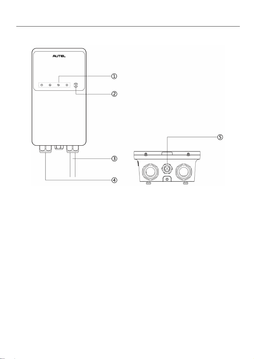
2.1 Product Overview
Autel MaxiCharger AC Wallbox Home
1. LED Indicators (from left to right):
Power LED
Internet Connection LED
Charging LED
Bluetooth Connection LED
2. RFID LED
3. EV Charging Cable
4. Bottom AC Inlet Hole
5. Bottom Ethernet Cable Port
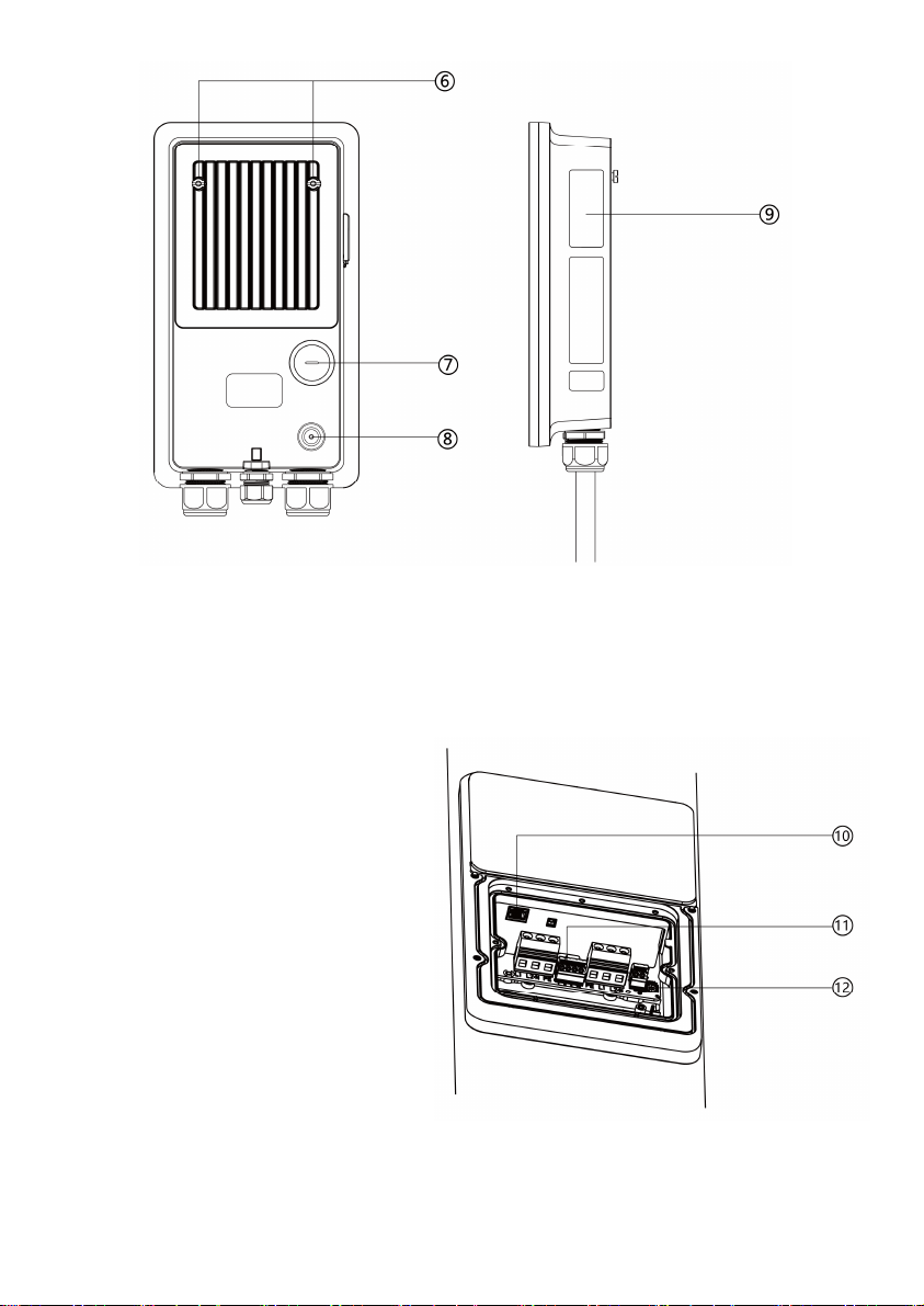
5
6. Mounting Screws
7. Rear AC Inlet Hole
8. Rear Ethernet Cable Port
9. Product Label
10. RJ45 Port
11. RS485 Port — connects the
RS485 cables
12. Current Selector — adjusts the
current for the charger

6
LED Description
LED Description
Power LED
Solid Green: The charger is on.
Not Illuminated: The charger is off.
Flashing Yellow: Data is being transmitted and/or firmware is
upgrading.
Solid Yellow: Firmware upgrade has failed.
Solid Blue: Data transmission has failed; will illuminate green in
five seconds.
Internet
Connection
LED
Solid Green: The charger is connected to the Internet.
Not Illuminated: The charger is not connected to the Internet.
Charging LED
Solid Blue: An EV is connected.
Flashing Blue: A schedule is active.
Flashing Green: An EV is charging.
Solid Green: A charge session has ended.
Not Illuminated: The charger is not connected.
Solid Orange: A recoverable error has occurred.
Solid Red: An irrecoverable error has occurred. (Please contact
support.)
Bluetooth
Connection
LED
Flashing Green: The charger is connected to a mobile device
via Bluetooth.
Flashing Blue: The charger is connected to the accessory VCI
(Vehicle Communication Interface) via Bluetooth. (VCI sold
separately.)
Flashing Cyan: The charger is connected to a mobile device and
a VCI device simultaneously via Bluetooth. (VCI sold separately.)
Not Illuminated: The charger is not connected via Bluetooth.
RFID LED
Illuminated: The RFID function is enabled. You can use the
RFID card to start and stop charging.
Not Illuminated: The RFID function is disabled.
7
2.2 Models
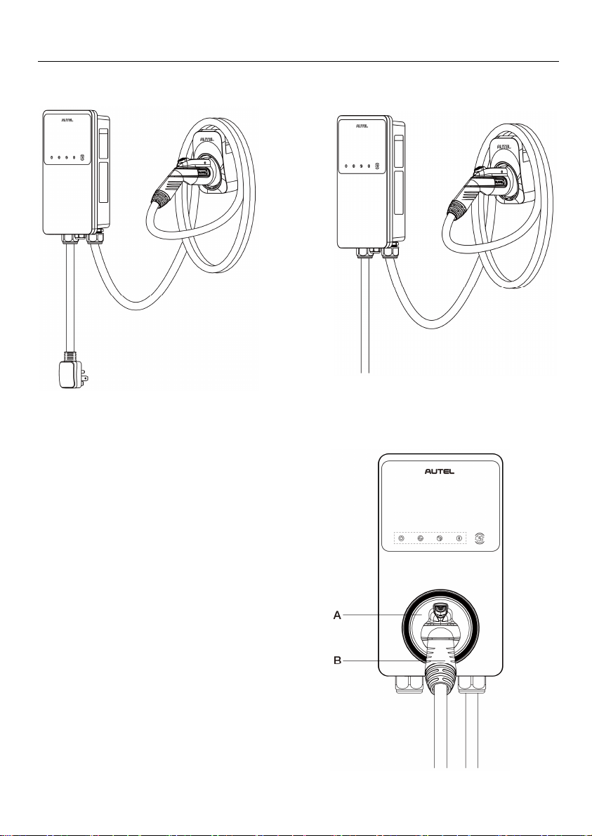
MaxiCharger AC Wallbox Home (Separate Holster)
NEMA Plug-in Version Hardwire Version
MaxiCharger AC wallbox Home
A. Holster
B. Connector

8
2.3 Specifications
Item Description
AC Power Output Rating
Maximum 7.6 kW (240 VAC @ 32 A model)
Maximum 9.6 kW (240 VAC @ 40 A model)
Maximum 12 kW (240 VAC @ 50 A model)
AC Power Input Rating
208/240 VAC, 60 Hz, single phase @ 16 A,
24 A, 32 A, 40 A, 48 A, 50 A
Circuit Breaker Options (A) 20 A, 30 A, 40 A, 50 A, 60 A, 70 A
Input Wiring Scheme Three wires: L1, L2, and Earth (no neutral)
Input Cord
NEMA 6-50
NEMA 14-50
Hardwired
Connector Type SAE J1772
Charging Cable Length 24.6 ft. (7.5 m)
Display 5 LEDs
Metering Meter IC, ± 1 %
Ground Fault Detection 20 mA CCID with auto retry
Protection
Overcurrent, overvoltage, undervoltage, integrated
surge protection
Connectivity
Bluetooth
Wi-Fi
Ethernet
RS485
Card Reader ISO 15693, ISO 14443, NFC

9
Item Description
Sub-G (Auto Open the Tesla
Charging Port)
Optional, only available on chargers with built-in holster
Communication Protocols
OCPP 1.6J
OCPP 2.0 (Optional, will be available soon)
Mounting Wall-mounted or floor using a pedestal
Enclosure Ratings
NEMA 4, indoor or outdoor installation
(NEMA cable length: 300 mm)
Operating Temperature -40 to 131 °F (-40 to 55 °C)
Storage Temperature -40 to 158 °F (-40 to 70 °C)
Dimension (
H x W x D
) 13” x 7” x 3” (335 x 187 x 85 mm)
Weight 14.8 lbs. (6.7 kg)
Safety and Compliance
NEC Article 625, UL 2594, UL2231-1, UL2231-2,
UL 1998, CSA C22.1
Automatic reset feature is provided.
AVERTISSEMENT
Caractéristique de réarmement automatique incluse.
Codes and Standards FCC Part 15 Class B
Warranty 3 years
Model
Maxi US AC W12-H
Maxi US AC W10-N14-H
Maxi US AC W10-N6-H
Maxi US AC W12
Maxi US AC W10-N14
Maxi US AC W10-N6
Maxi US AC W7-N14
Maxi US AC W7-N6
Maxi US AC W7-N14-H
Maxi US AC W7-N6-H
10
3
Installation
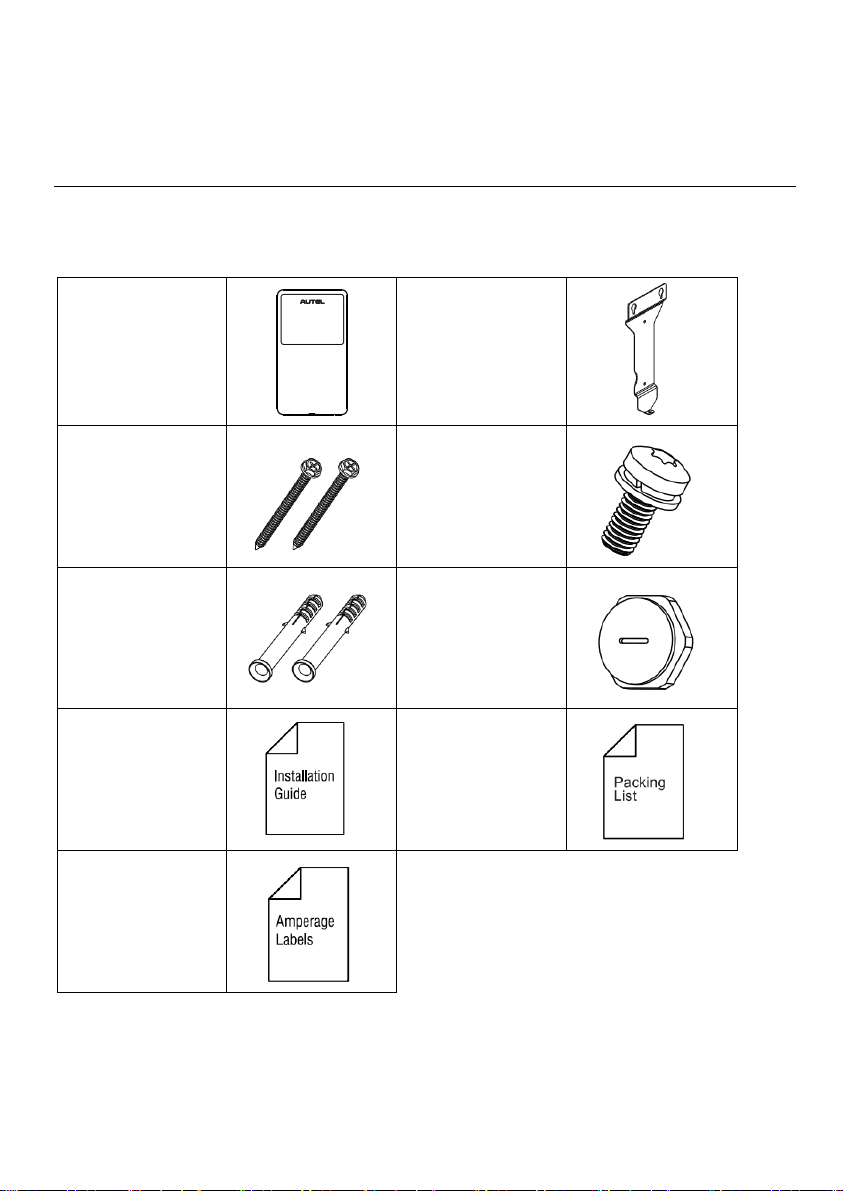
3.1 Unpacking
Make sure that all parts are delivered according to the order. Check the packaging for the
following parts.
Charging Station
Wall Dock
Screw (M6 x 50)
2 PCS
Screw (M5 x 12)
Wall Anchor
(5/16”)
2 PCS
Bottom Entry
Power Conduit
Plug (M32)
Installation Guide
Packing List
Amperage Labels
11
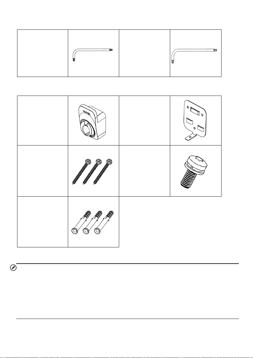
Tool Kit
Screwdriver (Type
T10)
Screwdriver (Type
T25)
Holster & Mounting
Holster
Wall Dock
Screw (M6 x 50)
3 PCS
Screw (M5 x 12)
Wall Anchor
(5/16”)
2 PCS
NOTE
1. The Holster & Mounting accessories are only applicable for the MaxiCharger AC
Wallbox Home (Separate Holster) model.
2. The list above does not necessarily include all the tools required for installation. We
recommend you read through the installation procedure and gather all the tools
needed prior to installation.
12
3.2 Electrical Design
3.2.1 Upstream Wiring
Charging stations are considered continuous load devices (EVs draw maximum load for long
durations); therefore, electrical branch circuits must be sized at 125% of the load for North
American installations, in accordance with National Electric Code (NEC) requirements. (For
other regions, refer to local code.) This means that for a maximum 50 A load at 208/240 V
output to an electric vehicle, 65 or 70 A breakers are required.
Wiring must be sized in accordance with NEC code for continuous load devices. Typically, 16
mm
2
or 10 mm
2
(6 AWG or 8 AWG) insulated electrical wire is used, depending upon the
rating of the circuit and the distance between the electrical panel and the charging station.
The terminal block accepts a maximum of 16 mm
2
(6 AWG).
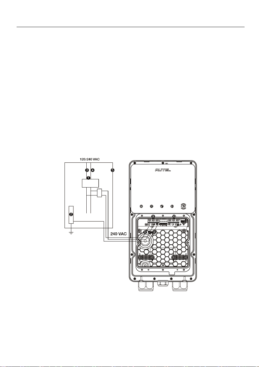
3.2.2 Upstream Wiring
240 VAC Panel
1. Main Breaker
2. PE Bus
3. L1
4. L2
13
5. Local Service or Sub Panel
6. L1
7. L2
8. PE
9. Input Terminal Block
10. Output Terminal Block
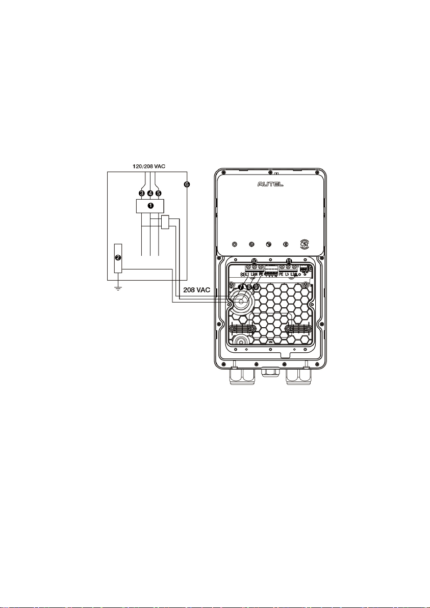
208 VAC Panel
1. Main Breaker
2. PE Bus
3. L1
4. L2
5. L3
6. Local Service or Sub Panel
7. L1
8. L2
9. PE
10. Input Terminal Block
11. Output Terminal Block
14
3.2.3 Grounding Requirements
The charger must be connected to a grounded, metal, and permanent wiring system. An
equipment-grounding conductor must be run with circuit conductors and connected to an
equipment-grounding terminal or lead on the charger.
A grounding conductor that complies with applicable codes must be grounded to earth at the
service equipment or, when supplied by a separate system, at the supply transformer.
Ensure that a grounding conductor that complies with all applicable codes is properly
grounded to earth at the service equipment, when supplied by a separate system, at the
supply transformer.
Neutral is not used to power the charger but must be properly connected to ground, at the
panel transformer, to provide necessary voltage reference relative to ground.
3.3 Preparing for Installation
3.3.1 Location
Install your charger on a flat and vertical surface capable of supporting its weight (e.g.,
a finished wall or pedestal). The maximum weight of a MaxiCharger AC Wallbox Home
is approximately 14.8 lbs. (6.7 kg).
Install the charger in a location that allows the charging cable to remain within its bending
tolerance.
Position the charger in a location where it is not vulnerable to being damaged.
3.3.2 Positioning
1. Determine the desired charging amperage and whether the desired circuit rating requires
a hardwired circuit. Choose based on the electrical capacity in the panel, the desired
speed of charging, and whether the user prefers a NEMA plug-in or hardwired installation.
Circuit Rating
Max Load
Estimated Range
per Hour
NEMA Plug-in
Hardwire
50 A 40 A Up to 38 miles/61 km
Yes Yes
40 A 32 A Up to 30 miles/48 km
Yes Yes
IMPORTANT
In Canada, a NEMA plug-in installation is only allowed with a 50 amp circuit.
15
The MaxiCharger AC Wallbox Home can also be wired for higher amperages. Consult
all applicable codes for breaker and wire sizing requirements. The field-wiring terminal
is rated to 105 °C and accepts a maximum of 6 AWG (16 mm²) wire.
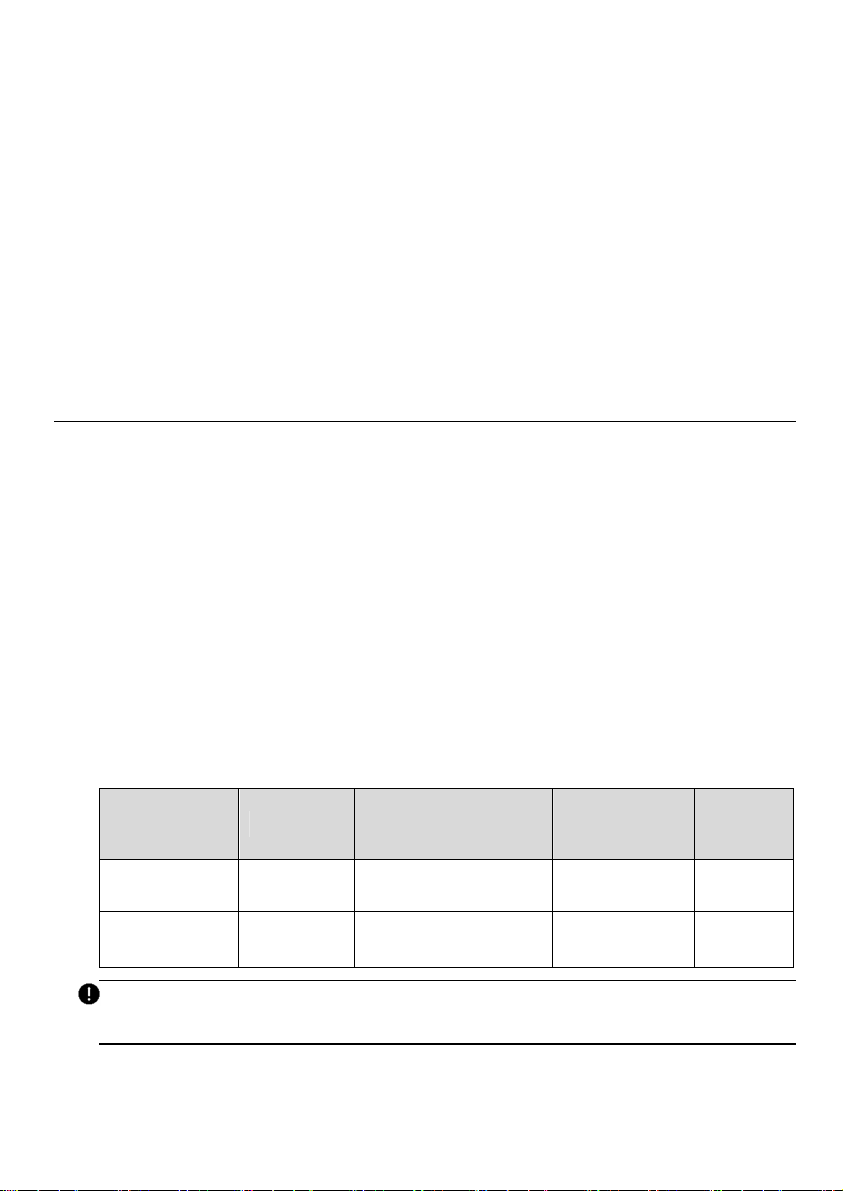
Circuit Rating
Max Load
Estimated Range
per Hour
NEMA Plug-in
Hardwire
70 A 50 A Up to 45 miles/72 km
No Yes
2. For NEMA plug-in installation, determine the purchased plug type, either a NEMA 6-50
or 14-50 plug.
3. Ensure the electrical panel supports a 240 V dedicated circuit with a new, dedicated, and
non-GFCI two-pole circuit breaker, in accordance with local codes and ordinances.
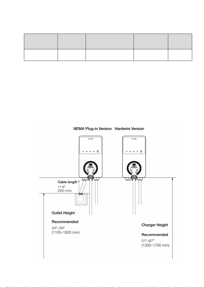
4. The recommended installation height is between 51 and 67 inches (1300 and 1700 mm).
For NEMA plug-in installation, the NEMA outlet should be located at least 18 inches (460
mm) from the ground adjacent to the position where the charger will be mounted.
5. The NEMA plug-in version requires an outdoor-rated and weather-resistant electrical
outlet, and the hardwire version requires and outdoor-rated and weather-resistant
hardwired installation.
16
3.4 NEMA Plug-in Outlet
This section introduces how to install a NEMA outlet if you do not have one already.
WARNING
Switch off the circuit breaker of the electrical outlet before installing your charger.
If you already have a NEMA outlet, ensure that it complies with local electrical codes and has
a designated circuit breaker and electrical wiring that are dimensioned appropriately.
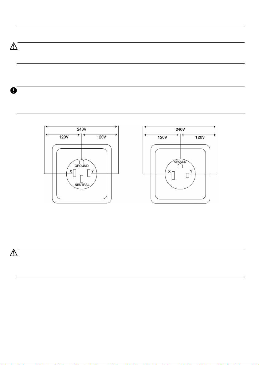
IMPORTANT
When installing a NEMA 14-50 outlet, ensure that the ground pin is facing up as shown per
the diagram.
NEMA 14-50P NEMA 6-50P
Ensure you have the correct permits for this electrical installation.
The NEMA outlet must be placed on the left side of the charger.
The power supply cable length is limited to 11.8” (300 mm).
CAUTION
To reduce the risk of fire, connect only to a circuit with a branch circuit over-current protection
of 50 A in accordance with ANSI/NFPA 70 (US) CSA C22.1 (Canada).
17
3.5 Installing the Charger
3.5.1 NEMA Plug-in Installation
1. To find the ideal mounting height of the charger:
DANGER
Risk of shock. Turn off the power to the outlet at the circuit breaker until the installation
is completed.
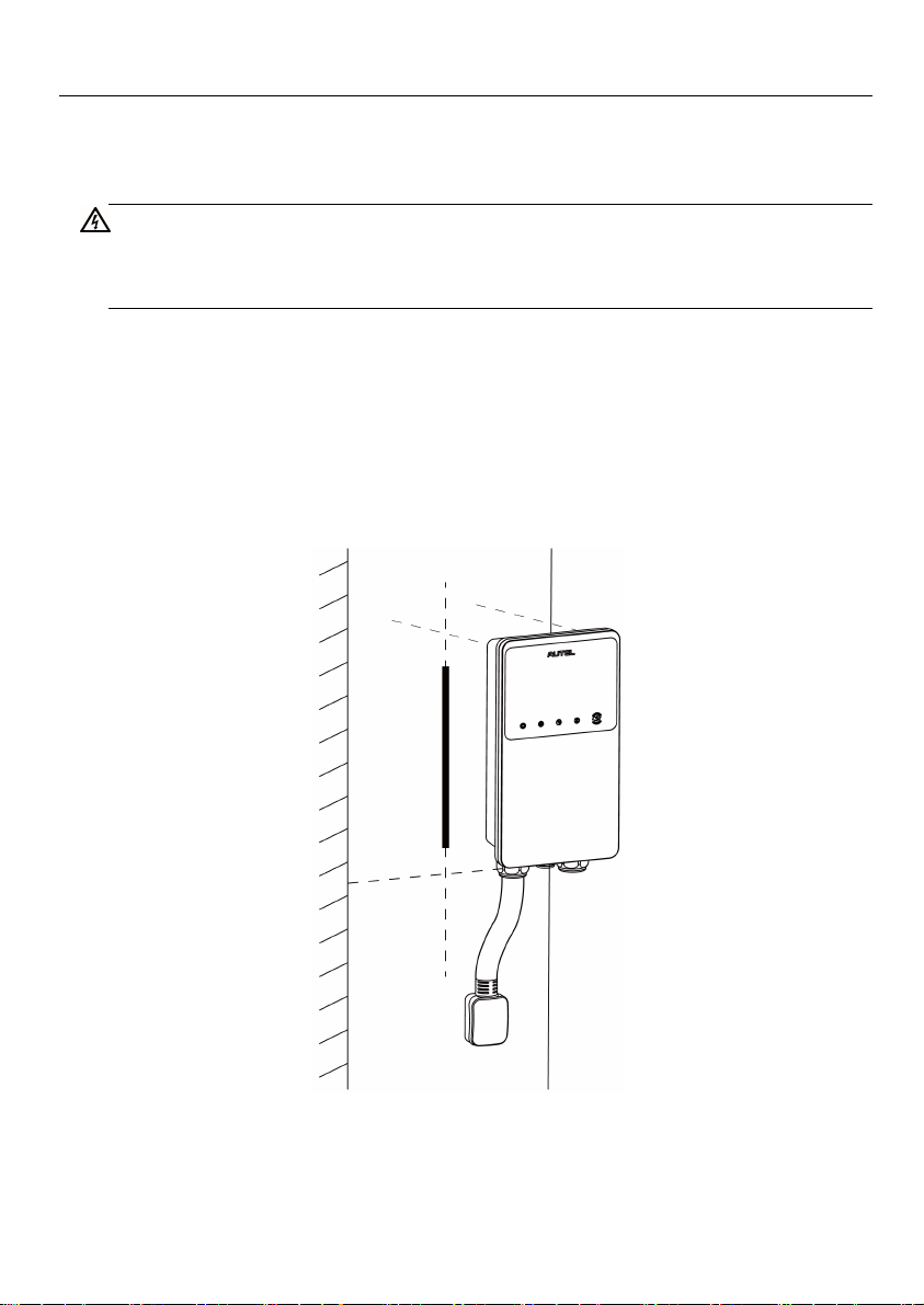
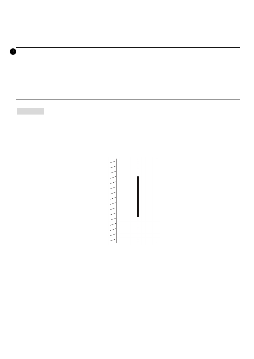
1) Find the wall stud nearest to the NEMA outlet using a wall stud finder. Draw a
vertical line of approximately 20" (50 cm) in line with the wall stud.
2) Plug the NEMA cable into the outlet, and position the charger centered on the
vertical line. Ensure that the NEMA cable has a slight curve and is not stretched.
3) Mark a horizontal line at the bottom of the charger.
4) Unplug the charger.
18
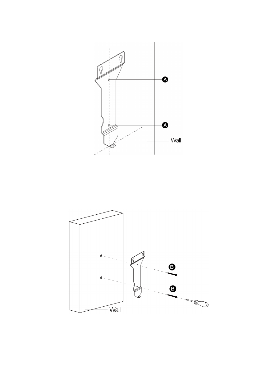
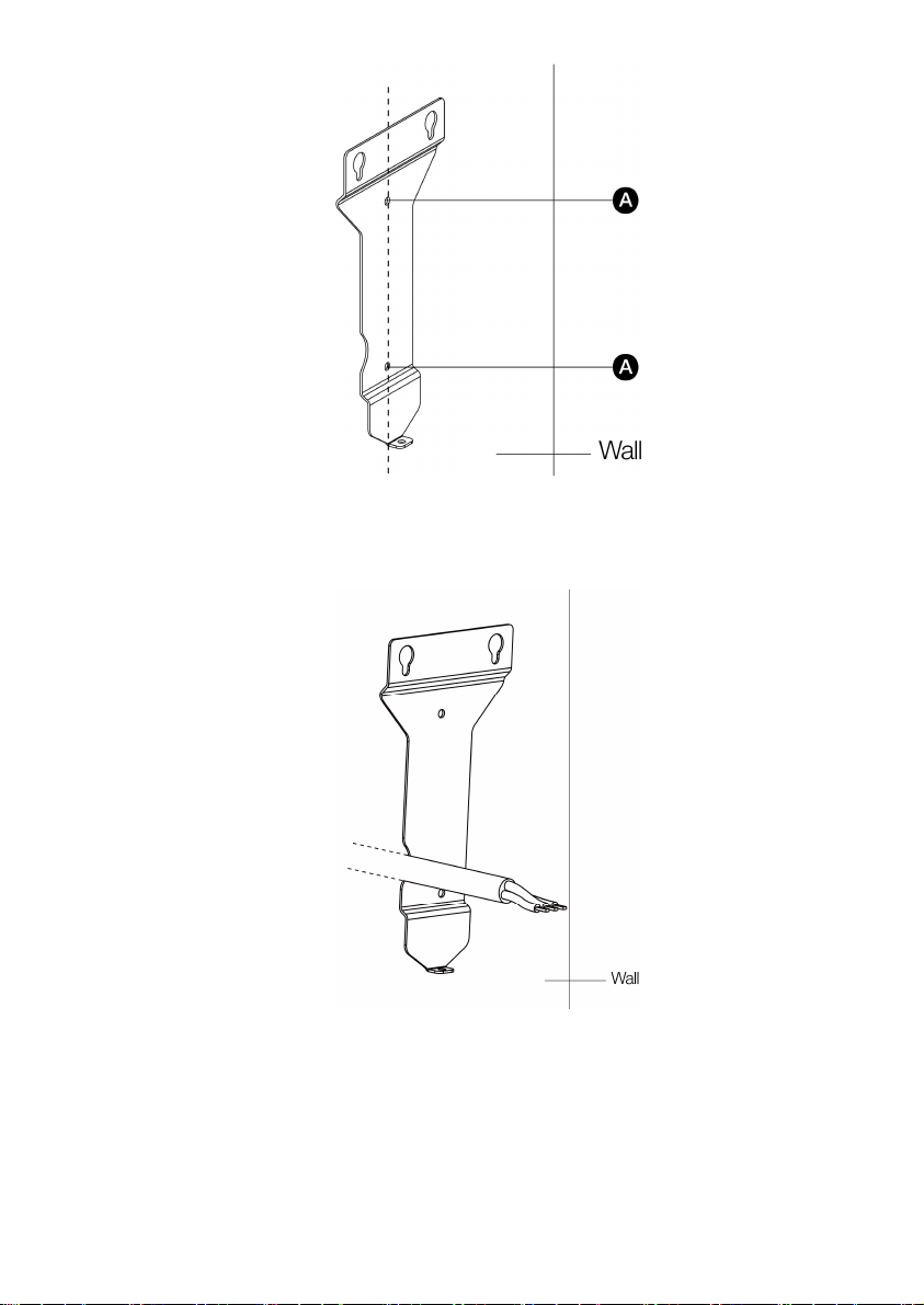
2. Place the wall dock with the bottom edge aligned with the horizontal line and the center
holes aligned with the vertical line. Mark the two lower mounting holes (A) and remove
the wall dock.
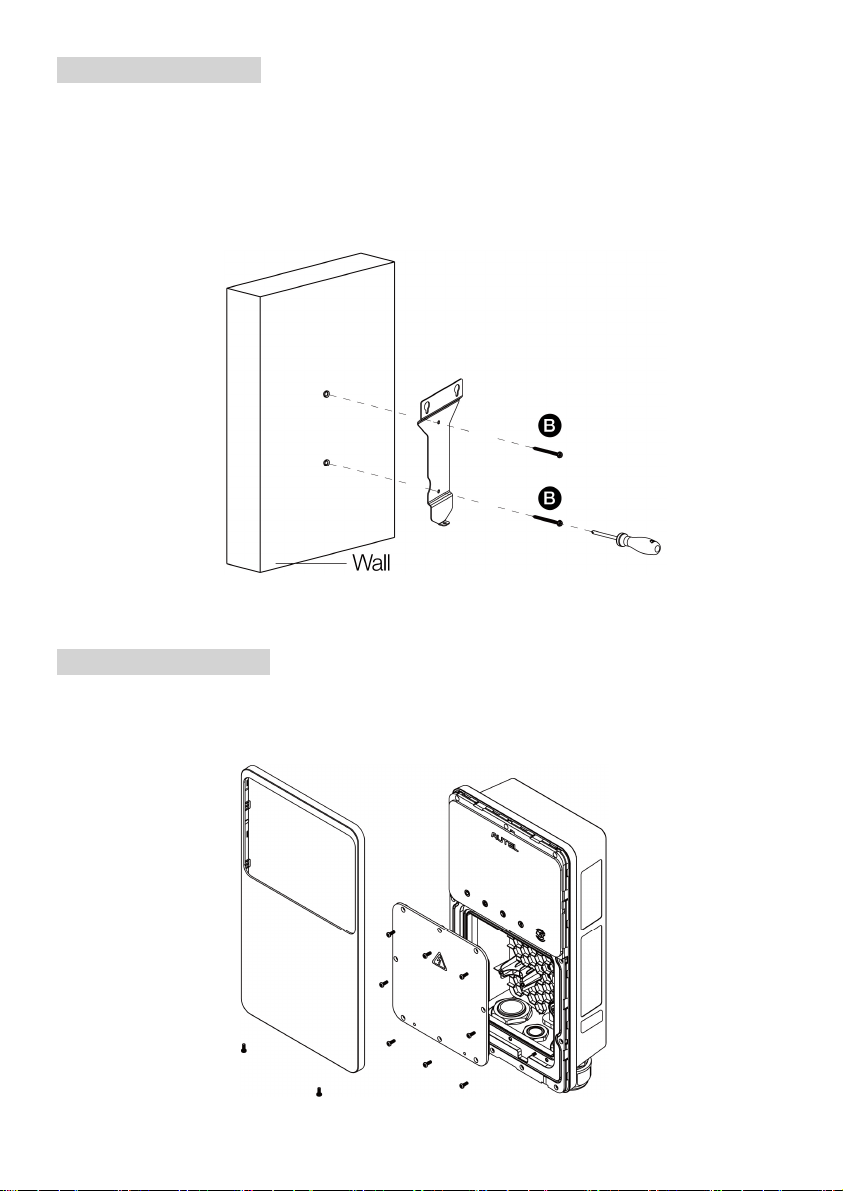
3. Drill two 5/16" holes and insert two 5/16" diameter wall anchors into the lower mounting
holes.
Attach the wall dock to the mounting location by screwing two M6 x 50 screws (B) into
the lower mounting holes. Tighten the screws using the screwdriver type PH2 (not
included in the package).
19
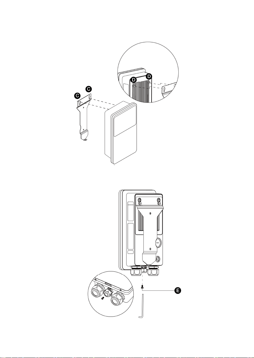
4. Attach the charger to the wall dock by inserting the mounting screws (D) on the back of
the charger into the two upper mounting holes (C). Slide the charger downwards.
5. Screw the M5 x 12 screw (E) into the hole at the bottom of the charger and tighten the
screw to secure the charger using the screwdriver type T25.
20
3.5.2 Hardwired Installation
The MaxiCharger AC Wallbox Home supports both rear entry and bottom entry wiring. Choose
the most appropriate wiring entry for your charger based on the placement of the wiring.
IMPORTANT
Both the rear entry and bottom entry locations are on the left side of the charger. Ensure
that you mount your charger in a location where the power supply wiring can be easily
accessed on the left side.
The rear entry cables should be put through the cable inlet holes prior to mounting the
charger to the wall dock.
Placement
1. Find the wall stud nearest to and on the right side of the power supply wiring using a wall
stud finder.
2. Draw a vertical line of approximately 20" (50 cm) in line with the wall stud at the
approximate height of your mounting.
3. Place the wall dock with the center holes aligned with the vertical line. Mark the two lower
mounting holes (A) and remove the wall dock.
21
4. For rear entry wiring, mark the cable exit where the AC input cable will come out from
the wall. Ensure that the cable exit matches the wall dock notch per the diagram below.
22
Mounting the Wall Dock
1. Drill two 5/16" holes and insert two 5/16" diameter wall anchors into the lower mounting
holes.
2. Attach the wall dock to the mounting location by screwing two M6 x 50 screws (B) into
the lower mounting holes. Tighten the screws using the screwdriver type PH2 (not
included in the package).
Preparing for Installation
Remove the covers from the charger by removing the screws using the screwdriver type
T10.
23
Removing the NEMA Cable (Optional)
In case you need to replace the NEMA cable with a Hardwire, remove the NEMA cable by
unscrewing the terminal screws per the diagram. Then loosen the cable gland and pull down
the NEMA cable.
24
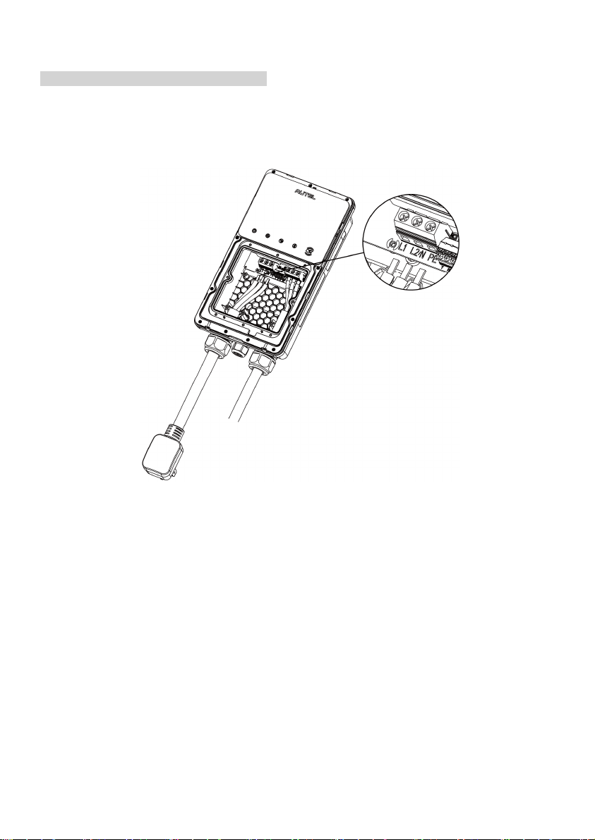
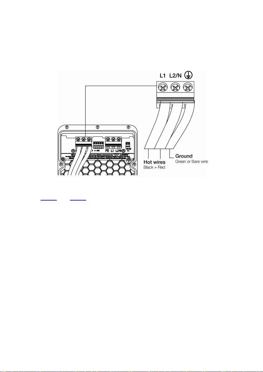
Power Supply Wiring
IMPORTANT
Use copper conductors with the maximum wire size of 6 AWG (16 mm²).
Ensure that the screws for the terminal blocks are properly tightened.
Ensure that there is no copper wire or debris left inside of the charger before switching
on the electrical power to the charger.
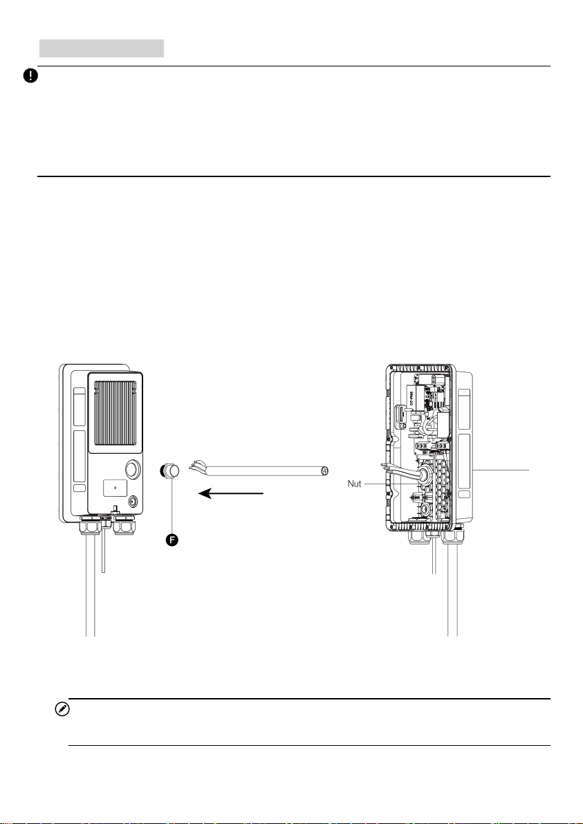
Step 1
Rear Entry
1. Remove the rear entry power conduit plug from the charger and replace it with the 3/4”
conduit fitting (F).
2. Insert the AC input cable into the conduit fitting and attach the conduit fitting to the
charger.
3. Screw the nut into the conduit fitting.
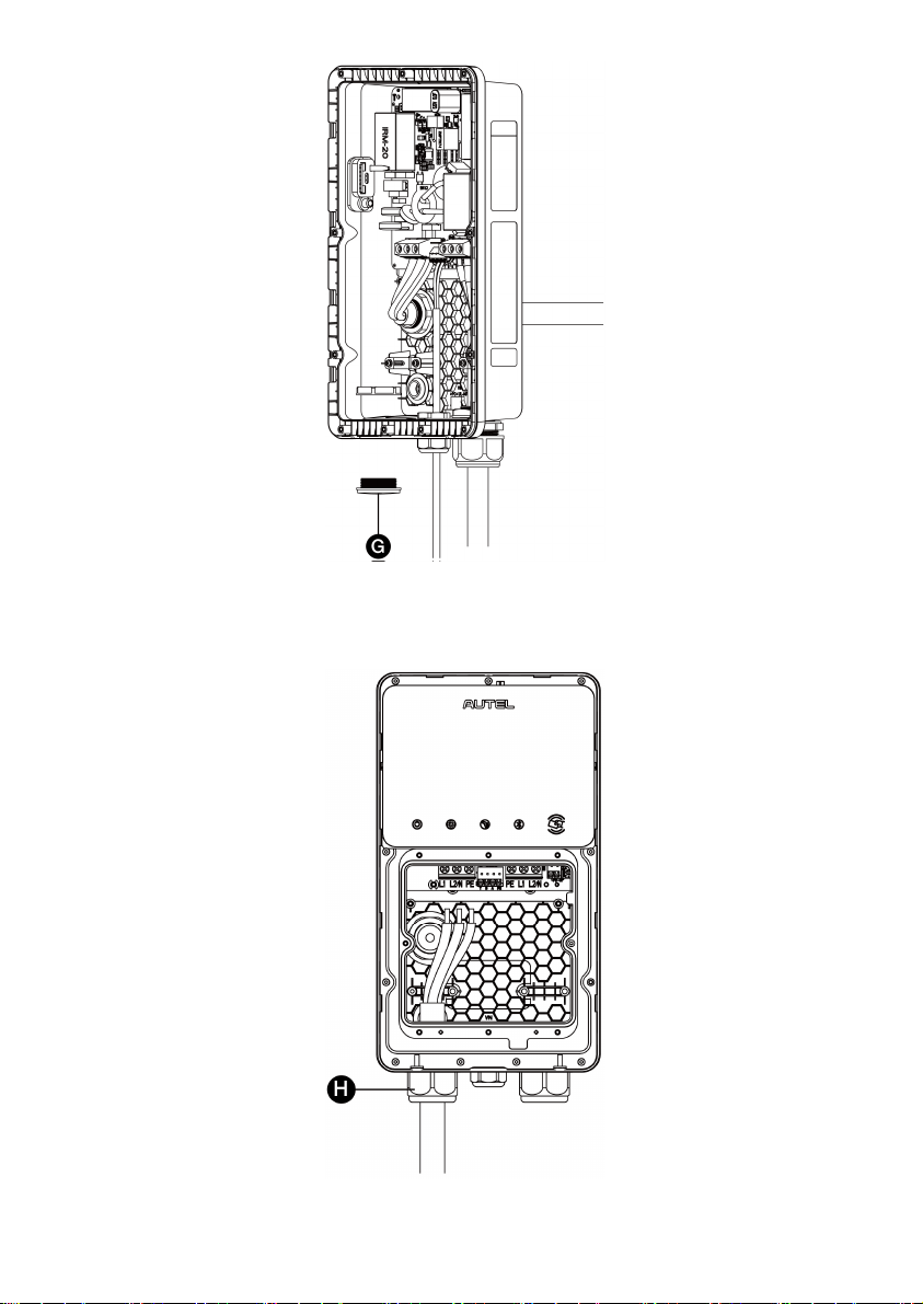
4. Remove the lower-left cable gland and install the bottom entry power conduit plug (G) to
the charger.
NOTE
The conduit fitting is not included in the package.
25
Bottom Entry
Insert the AC input cable into the inlet hole (H).
27
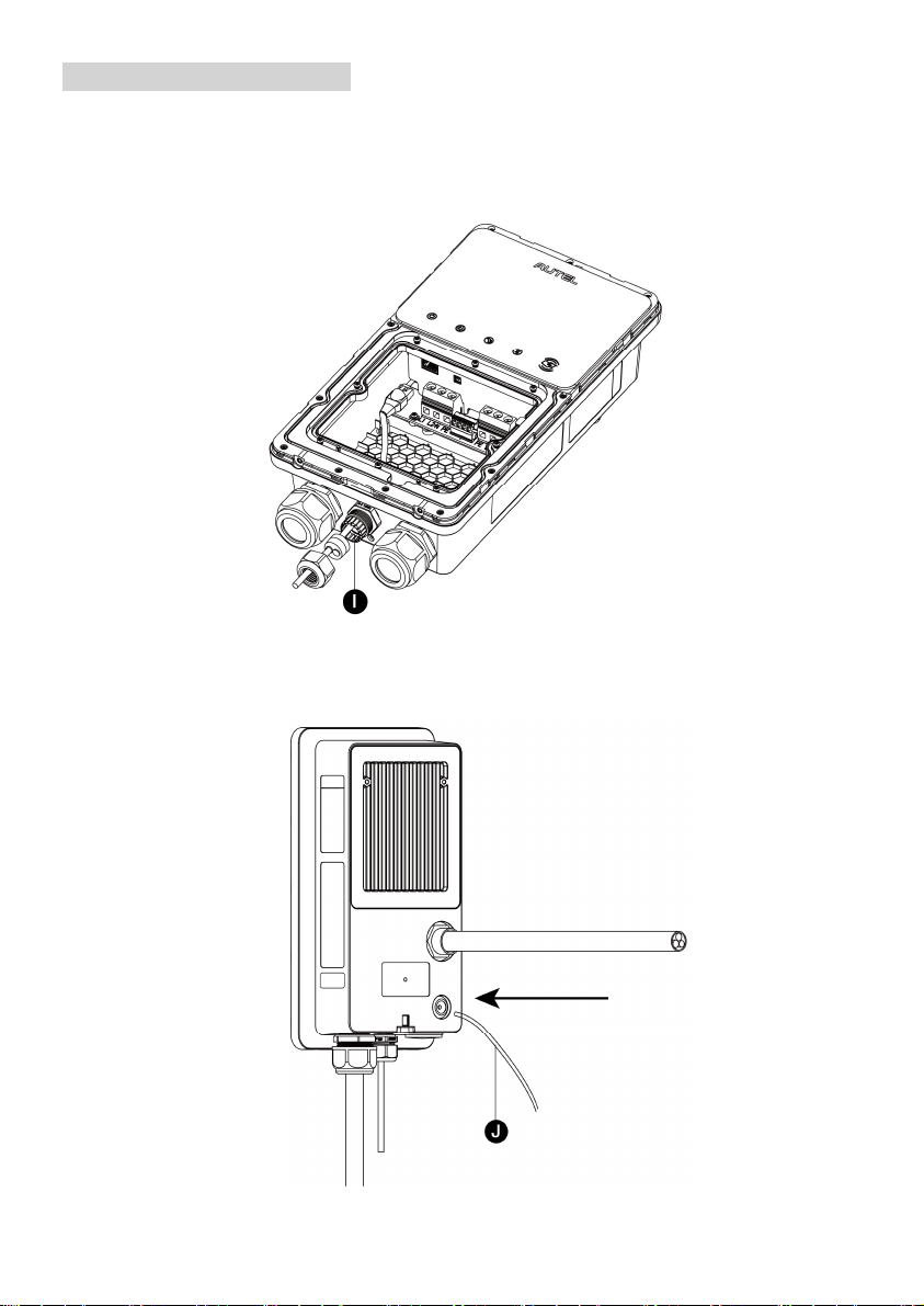
Connecting the Ethernet Cable
Step 1
Bottom Entry
Put the Ethernet cable with the RJ45 plug through the bottom Ethernet cable port (I).
Rear Entry
1. Pierce the rubber grommet and put the Ethernet cable through it.
2. Make a RJ45 plug and connect it with the Ethernet cable.
28
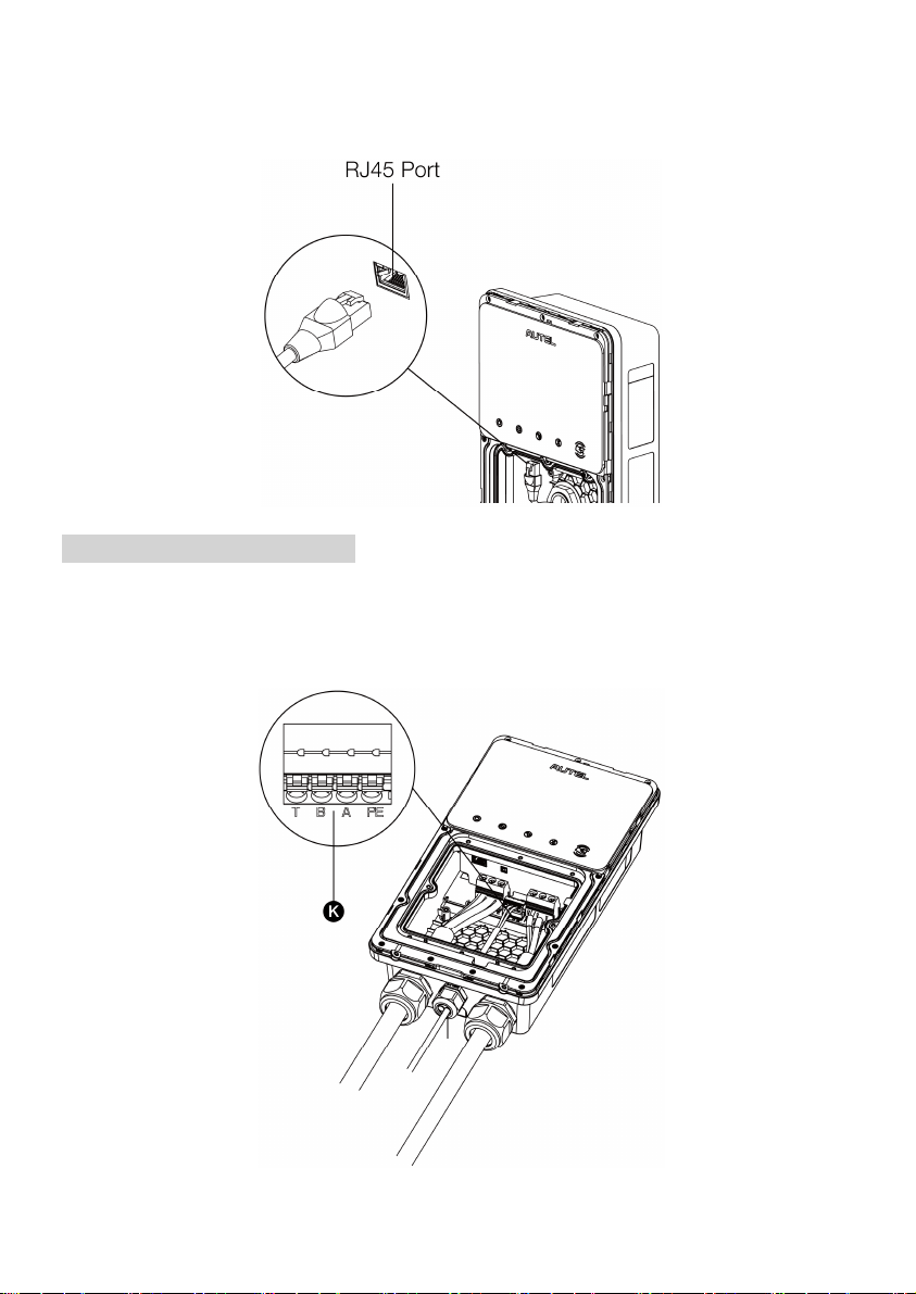
Step 2
Plug the cable into the RJ45 port as shown.
RS485 Cables Wiring (Optional)
If you need to connect the RS485A and RS485B cables, insert the cables through the bottom
Ethernet cable port (K) first. Then connect the cables to the RS485 port as specified on the
terminal block, respectively.
29
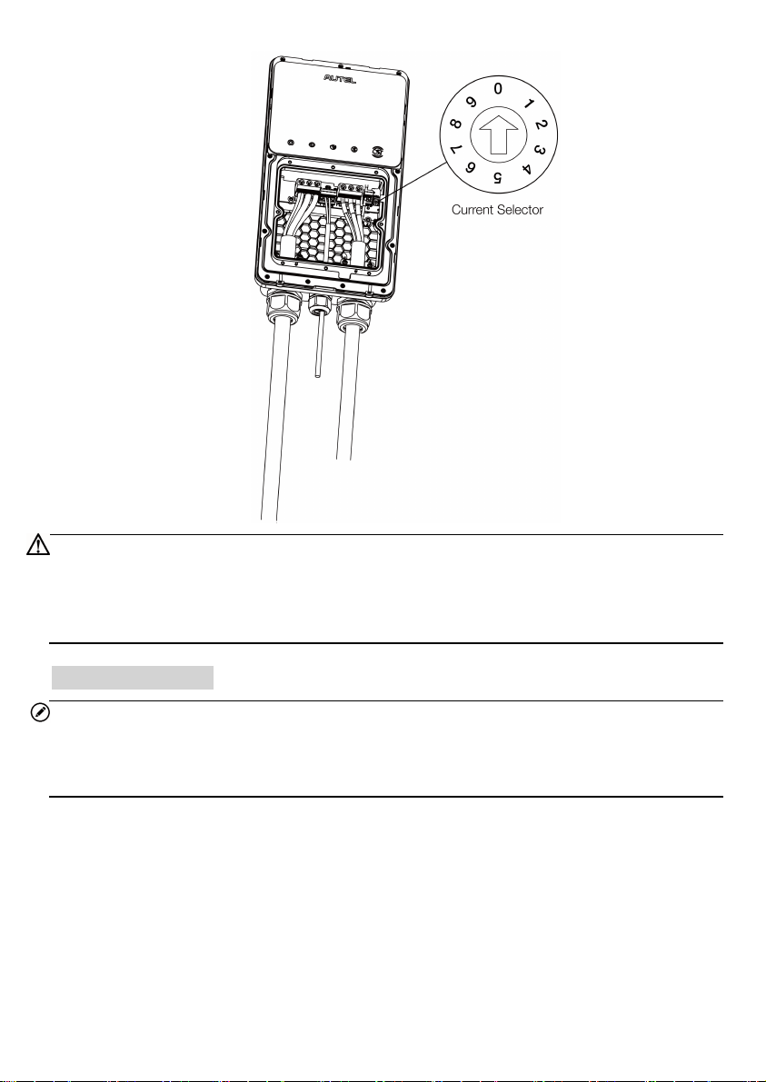
Adjusting the Rated Current
The MaxiCharger AC Wallbox Home allows you to manually set a lower maximum current
using a current selector when installing your charger on a circuit rated lower than the
maximum rating for your charger.
1. Remove the covers and locate the current selector.
2. Use a flathead screwdriver to set the rotary switch to the appropriate position per the
diagram below.
Position Amperage (A) Circuit Breaker Rating
0 Not in Use N/A
1 16 20
2 24 30
3 32 40
4 40 50
5 48 60
6 50 70
7 Not in Use N/A
8 Not in Use N/A
9 Not in Use N/A
NOTE
When the rotary switch is at 0, 7, 8 or 9, the corresponding amperage will still be
16, 50, 50, and 50, respectively.
The maximum current is limited by the power rating of a charger as follows:
— For 7 kW model: 32 A
— For 9.6 kW model: 40 A
— For 12 kW model: 50 A
3. When the current of your charger is set lower than the maximum rating, choose the
correct current value from the Amperage Labels and affix it over the existing label on the
charger.
30
CAUTION
To reduce the risk of fire, only connect your charger to a circuit with a branch circuit over-
current protection of 125% of the selected maximum amperage setting of the device in
accordance with ANSI/NFPA 70 (US) CSA C22.1 (Canada).
Installing the Holster
NOTE
The procedures below are only applicable for the “Separate Holster” model.
Place the holster on a location where no tension is applied to the charging cable.
1. Place the wall dock on the wall and level it using a spirit level.
2. Mark the three mounting holes (I) with a pencil and drill three 5/16" holes.
3. Insert three 5/16" diameter wall anchors (J) into the holes.
4. Attach the wall dock to the mounting location by screwing three M6 x 50 screws (K) into
the holes. Tighten the screws using the screwdriver type PH2.
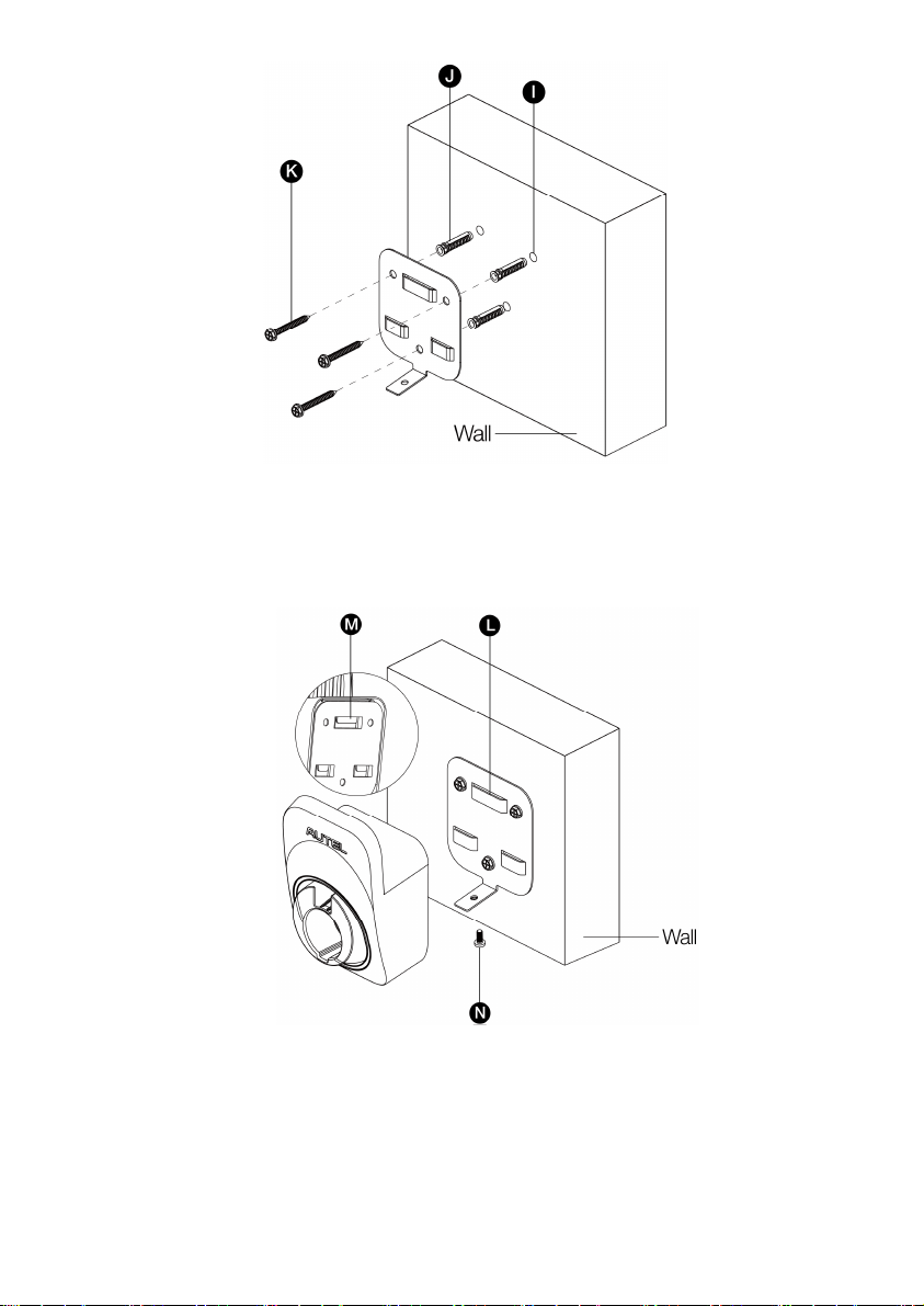
31
5. Align the three connecting points (M) of the holster with the installation slots (L). Make
sure they are connected securely.
6. Screw the M5 x 12 screw (N) into the hole at the bottom of the holster and tighten the
screw to secure the holster using the screwdriver type T25.
7. Drape the charging cable over the top of the charger or holster and dock your EV
connector in it.
32
4
Operation
4.1 Powering on
If you have installed a NEMA plug-in model, plug it into the outlet.
For all models, once all electrical connections have been safely made, switch on the power to
the circuit from the circuit breaker and wait for the power supply to come on. There will be a
series of self-check starts, making sure that the charger works correctly and safely. The power
LED should illuminate green. If a recoverable error is detected, the charging LED illuminates
orange; if the error cannot be recovered, it illuminates red.
Warning
Be careful when you work with electricity.
4.2 Adding Your Charger
To add your charger
1. Scan the QR code below to download the Autel Charge app to your mobile
device from the Google Play or App Store. For iOS users, you will be redirected
to the App Store; for Android users, you will be redirected to the Google Play.
2. Open the Autel Charge app on your mobile device, and log in with your phone
number or email. If you do not yet have an account, register with your phone
number first.
3. Scan the QR code or enter the serial number and PIN code, which can be all
found on the Installation Guide, to add the charger.
33
4.3 Start Charging
Caution
During the charge session, do not disconnect the connector. There is a risk of damage to the
connector or your EV charging port.
1. Remove the connector from the holster.
2. Plug the connector into your EV charging port.
3. Choose one of the following ways to start a charge session:
—
If the Auto Start function is enabled in the Autel Charge app, the charger will
automatically start charging once the connector is properly connected.
—
Use the Autel Charge app by tapping Start on the Charge screen.
—
If you have set a charging schedule in the Autel Charge app, the charger will initiate
a charge session automatically as scheduled.
—
If the RFID function is enabled, tap your RFID card on the RFID reader.
NOTE
Ensure your EV is charging. The charging LED on the charger should be flashing green. If
you suspect the vehicle is not charging properly, try reconnecting the charging cable or contact
customer support.
4.4 Stop Charging
NOTE
If you disconnect the EV charging cable during the charge session, the charger
automatically disconnects the power supply. This stops all charging operations.
When your vehicle is fully charged, the charger will automatically disconnect the power
supply.
1. To stop charging, you can choose either of the following two ways:
Wait for the charge session to end and no further actions are required in the case
of scheduled charging or Auto Start.
—
The charging LED will illuminate solid green.
—
The Autel Charge app displays that your EV is fully charged.
End the charge session by tapping Stop on the Charge screen. Or, if the RFID
function is enabled, tap the RFID card on the RFID reader again.
2. Unplug the connector from your EV and return it to the holster.

34
5
Troubleshooting and Service
5.1 Troubleshooting Table
Item
Problems Solutions
1
The charger is successfully added,
but the Bluetooth connection fails.
Check whether the QR code on the charger
is consistent with the QR code on the
Installation Guide. If so, make sure the
Bluetooth is enabled on your mobile device;
if not, contact customer support.
2
The charge session does not start
as scheduled.
Do not insert the connector into your EV
charging port before setting up a charging
schedule for the first time. Insert the EV
charging cable after the schedule is set up.
3 Over-voltage
Use the multimeter to check whether the
voltage on the power input is too high. If the
result is greater than or equal to 120 % of the
rated voltage (276 V), contact local power
grid company.
4
Under-voltage
Use the multimeter to check whether the
voltage on the power input is not sufficient. If
the result is less than or equal to 70 % of the
rated voltage (161 V), contact local power
grid company.
5
Ground fault Make sure the charger is grounded correctly.
6
Power failure
Make sure the switch to the circuit breaker is
on.

35
Item
Problems Solutions
7
Over-heating
Check whether the EV charging cable is
securely connected.
Ensure the operating temperature is
within the specified range on the
product label.
Stop charging. Restart charging until it
is within the operation temperature
range.
8
Residual current detected
Unplug the vehicle and plug in again. If the
problem persists, contact customer support.
9 Bluetooth communication failure
Make sure the Bluetooth is enabled on
your mobile device and the charger is
powered on and operating properly.
Forget the charger in the Bluetooth
settings on your mobile device and pair
the charger to your device via Bluetooth
again.
If the problem persists, contact
customer support.
10 Update failure via Bluetooth
Make sure the charger is in idle status.
Make sure the Bluetooth connection is
working properly.
If the problem persists, contact
customer support.
11 Internet connection fails
Try to connect another device to the
same Internet, verifying the Internet
connection is working properly.
If the problem persists, contact
customer support.

36
5.2 Service
If you cannot find solutions to your problems with the aid from the table above, please contact
our technical support.
AUTEL
Website: www.autelenergy.com
Phone: (844) 765-0150
Email: [email protected]
Address: 36 Harbor Park Drive, Port Washington, New York, USA 11050

37
6
Compliance
FCC regulatory conformance
:
This device complies with Part 15 of the FCC Rules. Operation is subject to the following two
conditions:
(1) This device may not cause harmful interference.
(2) This device must accept any interference received, including interference that may cause
undesired operation.
NOTE: This equipment has been tested and found to comply with the limits for a Class B
digital device, pursuant to part 15 of the FCC Rules. These limits are designed to provide
reasonable protection against harmful interference in a residential installation.
This equipment generates uses and can radiate radio frequency energy and, if not installed
and used in accordance with the instructions, may cause harmful interference to radio
communications. However, there is no guarantee that interference will not occur in a
particular installation. If this equipment does cause harmful interference to radio or television
reception, which can be determined by turning the equipment off and on, the user is
encouraged to try to correct the interference by one or more of the following measures:
- Reorient or relocate the receiving antenna.
- Increase the separation between the equipment and receiver.
- Connect the equipment into an outlet on a circuit different from that to which the receiver is
connected.
- Consult the dealer or an experienced radio/TV technician for help
NOTE: The manufacturer is not responsible for any radio or TV interference caused by
unauthorized modifications to this equipment. Such modifications could void the user’s
authority to operate the equipment.
RF Exposure
This equipment complies with FCC radiation exposure limits set forth for an uncontrolled
environment. This equipment should be installed and operated with minimum distance of 20
cm between the radiator and your body. This transmitter must not be co-located or operating
in conjunction with any other antenna or transmitter.
IC regulatory conformance:
This device complies with CAN ICES-3 (B)/NMB-3(B).
This device contains licence-exempt transmitter(s)/receiver(s) that comply with Innovation,
Science and Economic Development Canada's licence-exempt RSS(s). Operation is subject
to the following two conditions:

38
(1) This device may not cause interference.
(2) This device must accept any interference, including interference that may cause undesired
operation of the device.
Cet appareil est conforme à la norme CAN ICES-3 (B)/NMB-3 (B).
Cet appareil contient des émetteurs / récepteurs exempt (s) de licence qui sont conformes
aux RSS exemptes de licence d'Innovation, Sciences et Développement économique Canada.
Son fonctionnement est soumis aux deux conditions suivantes:
(1) Cet appareil ne doit pas provoquer d'interférences.
(2) Cet appareil doit accepter toute interférence, y compris les interférences susceptibles de
provoquer un fonctionnement indésirable de l'appareil.
RF Exposure
This equipment complies with IC radiation exposure limits set forth for an uncontrolled
environment. This equipment should be installed and operated with minimum distance of 20
cm between the radiator and your body. This transmitter must not be co-located or operating
in conjunction with any other antenna or transmitter.
Cet équipement est conforme aux limites d’ exposition aux rayonnements de la IC établies
pour unenvironnement non contrôé. Cet équipement doit être installé et fonctionner à au
moins 20cm de distance d’un radiateur ou de votre corps.
