1 of 8
ISSUED: 09-15-11 SHEET #:125-9244-1
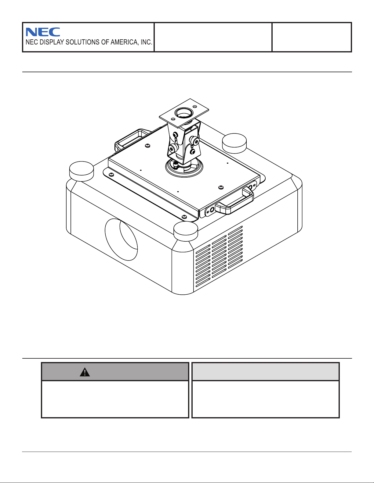
Model: NP750CM
Installation and Assembly:
Projector Adapter Plate
• Itistheresponsibilityoftheinstallertoensure
thattheprojectorisproperlyventilated.Spacers
areprovidedtoraisethemountofftheprojector
surface.
CAUTION
• Installermustverifythattheceilingwillsafely
supportfourtimesthecombinedweightofall
attachedequipmentandhardware.
WARNING
Model: PX750CM
Installation and Assembly:
Adapter Plate for NEC Projector
Model PX-750U
IMPORTANT! Read entire instruction sheet before you start installation and assembly.
Max Load Capacity:
60lb(22.3kg)
2 of 8
ISSUED: 09-15-11 SHEET #:125-9244-1
A
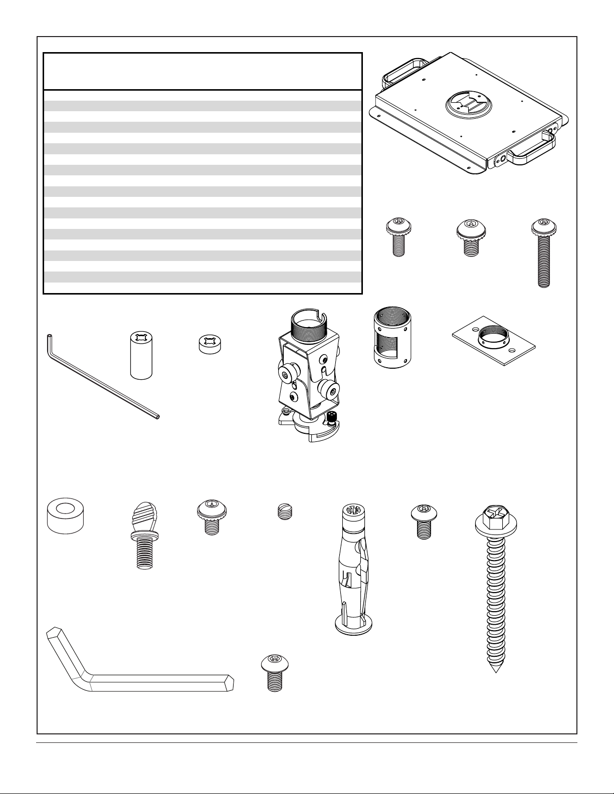
NOTE: Readentireinstructionsheetbeforeyoustartinstallationandassembly.
Beforeyoustartmakesureallpartslistedareincludedwithyourproduct.
B C D
E F G
H I
J
K
L
M
N
R
Description Qty. Part #
A adapterassembly 1 056-1061
B M4x12mmsocketpinserratedwasherheadscrew 4 510-1079
C M5x10mmsocketpinserratedwasherheadscrew 4 510-1126
D M4x40mmsocketpinserratedwasherheadscrew 2 510-1091
E 4mmallenwrench 1 560-9646
F .375spacer 2 590-1140
G .75spacer 2 590-1300
H projectormountassembly 1
055-1950
I columnconnector 1 580-1025
J
ceilingplate 1
580-1042
K
.25"x.5"x.25"spacer
2 590-1050
L
#10-32x3/8"thumbscrew
1 560-1107
M
#10-32x3/8"socketpinserratedwasherheadscrew
1 520-1151
N
10-32x3/8"slottedsetscrew
3 520-1187
O
concreteanchor
2 590-0320
P
#10-32x3/8"socketpinscrew
2 520-1084
Q
#14x2.5"woodscrew
2 5S1-015-C03
R
5mmallenwrench
1 560-0216
S
M5x10mmtype-Fscrew
1 520-1164
Parts List
P
Q
O
S
3 of 8
ISSUED: 09-15-11 SHEET #:125-9244-1
J
Q
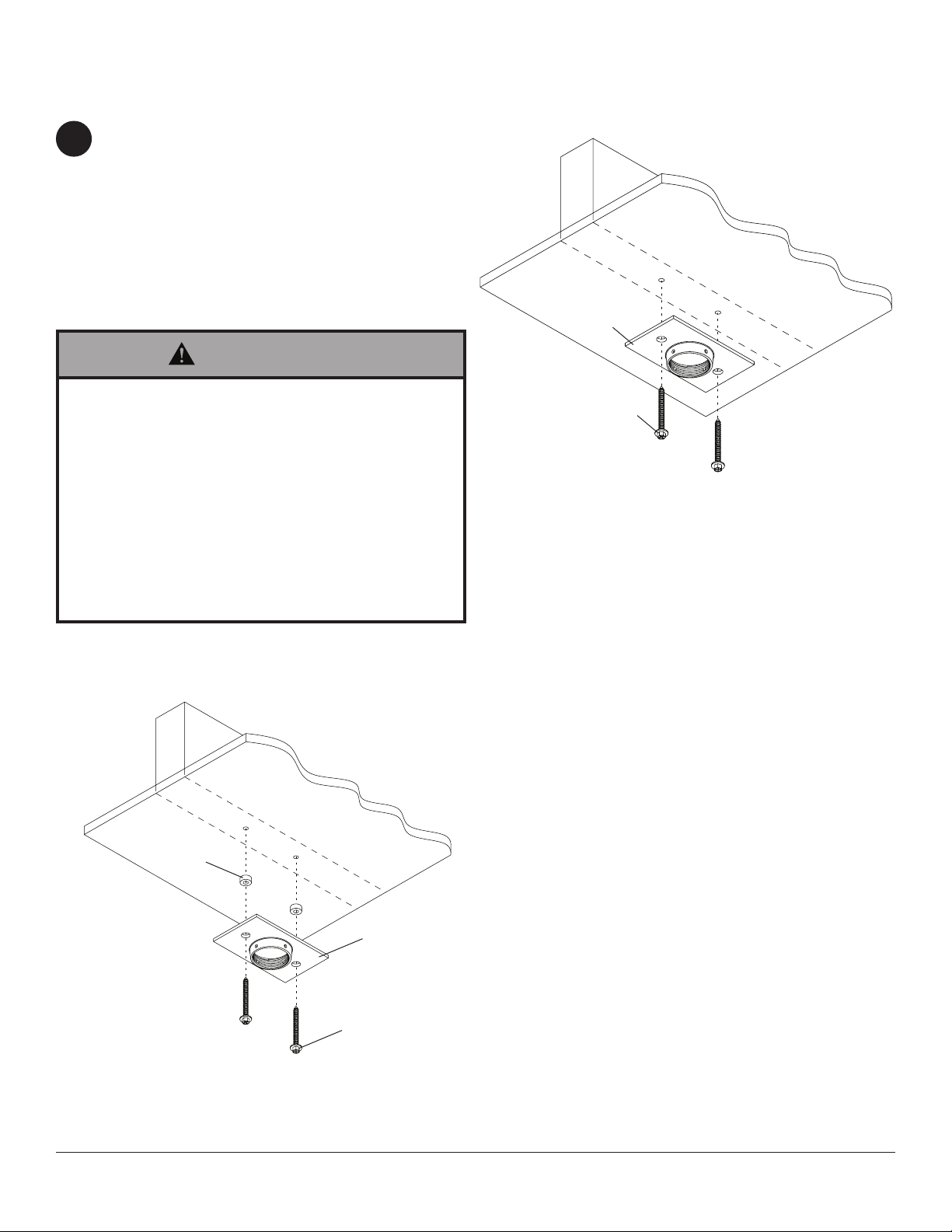
Drilltwo5/32"(4mm)dia.holestoaminimum
depthof2.5"(64mm).Attachceilingplate(J)
toceilingwithtwo#14x2.5"woodscrews(Q)
using3/8"(10mm)socketwrenchasshownin
gure1.1.
NOTE:Foroptionalcordmanagement,install
twospacers(K)betweenceilingplate(J)and
ceilingasshowningure1.2.
Skip to step 2 for ush mount installation.
Skip to step 3 for extension column installation.
Installation To Wood Joist Finished Ceilings, Exposed Wood Joists,
or Wood Beam Ceilings
• Tightenwoodscrewssothatceilingplateisrmly
attached,butdonotovertighten.Overtighteningcan
damagethescrews,greatlyreducingtheirholding
power.
• Nevertighteninexcessof80in•lb(9N.M.).
• Makesurethatmountingscrewsareanchoredinto
thecenterofthestuds.Theuseofan"edgetoedge"
studnderishighlyrecommended.
• Itistheresponsibilityoftheinstallertoverifythatthe
supportingsurfacewillsafelysupportthecombined
loadofallattachedhardwareandcomponents.
WARNING
1
IMPORTANT:BesuretodrillholesintothejoistCENTER!
WOODJOIST
WOODJOIST
CEILING
CEILING
J
Q
K
g. 1.1
g. 1.2
4 of 8
ISSUED: 09-15-11 SHEET #:125-9244-1
Installation to Concrete Ceilings
• Tightenwoodscrewsrmly,butdonotovertighten.
Overtighteningcandamagethescrews,greatly
reducingtheirholdingpower.
• Nevertighteninexcessof80in•lb(9N.M.).
• Alwaysattachconcreteexpansionanchorsdirectly
toload-bearingconcrete.
• Neverattachconcreteexpansionanchorstocon-
cretecoveredwithplaster,drywall,orothernishing
material.Ifmountingtoconcretesurfacescovered
withanishingsurfaceisunavoidable,thenish-
ingsurfacemustbecounterboredasshownbelow.
Besureconcreteanchorsdonotpullawayfrom
concretewhentighteningscrews.Ifplaster/drywall
isthickerthan5/8"(16mm),customfastenersmust
besuppliedbyinstaller.
WARNING
• Concretemustbe2000psidensityminimum.Lighterdensityconcretemaynotholdconcreteanchor.
• Installermustverifythatthesupportingsurfacewillsafelysupportthecombinedloadoftheequipmentandallat-
tachedhardwareandcomponents.
WARNING
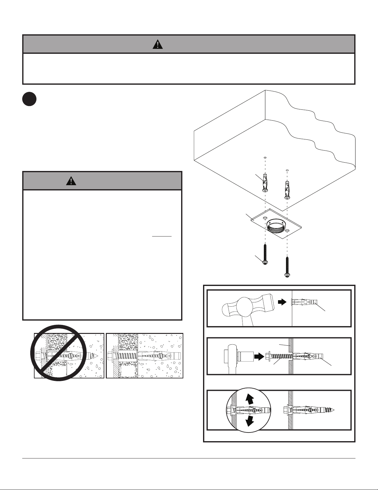
Drilltwo5/16"(8mm)dia.holestoaminimumdepth
of2.5"(64mm).Insertanchors(O)inholesushwith
wall.Placeceilingplate(J)overanchorsandsecure
usingtwo#14x2.5"screws(Q).
IMPORTANT:Itistheresponsibilityoftheinstallerto
verifythattheceilingwillsafelysupportthecombined
loadofallattachedhardwareandcomponents.
Skip to step 2 for ush mount installation.
Skip to step 3 for extension column installation.
1
SOLID
CONCRETE
CEILING
1
3
2
Drillholesandinsertanchors(O).
Placeplate(B)overanchors(S)andsecurewithscrews(Q).
Tightenallfasteners.
J
Q
concrete
surface
CUTAWAY VIEW
INCORRECT CORRECT
wall
plate
wall
plate
plaster/
drywall
plaster/
drywall
concrete
concrete
J
O
O
O
Q
5 of 8
ISSUED: 09-15-11 SHEET #:125-9244-1
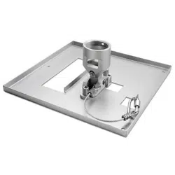
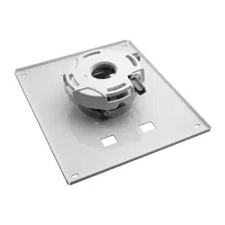
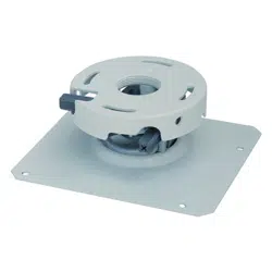
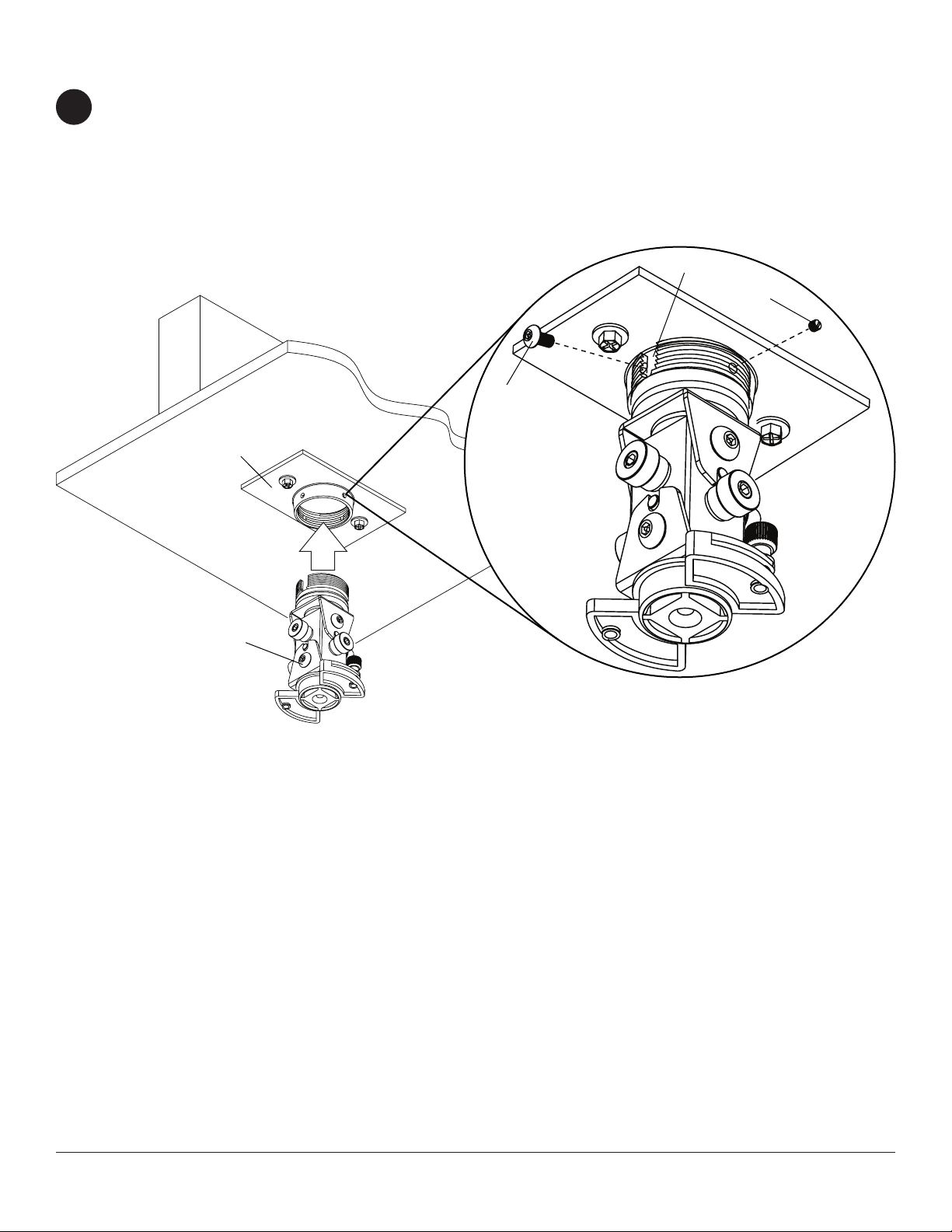
Handthreadprojectormountassembly(H)intoceilingplate(J)asshowningure2.1.Alignthenotchofprojector
mountassemblywithoneofthefourholesinceilingplate(J)andsecurewithanM5x10mmsocketpinscrew(S)
asshownindetail1.
NOTE:Slottedsetscrew(N)isusedtojamagainstthethreadsoftheprojectormountassemblytopreventany
excessmovementoftheprojectormountassembly(H).Donotovertightenscrew;overtighteningscrewwilldamage
threadsmakingitdifculttoseparateprojectormountassemblyfromceilingplate.
Flush Mount Installation
2
g. 2.1
DETAIL 1
J
S
N
H
NOTCH
6 of 8
ISSUED: 09-15-11 SHEET #:125-9244-1
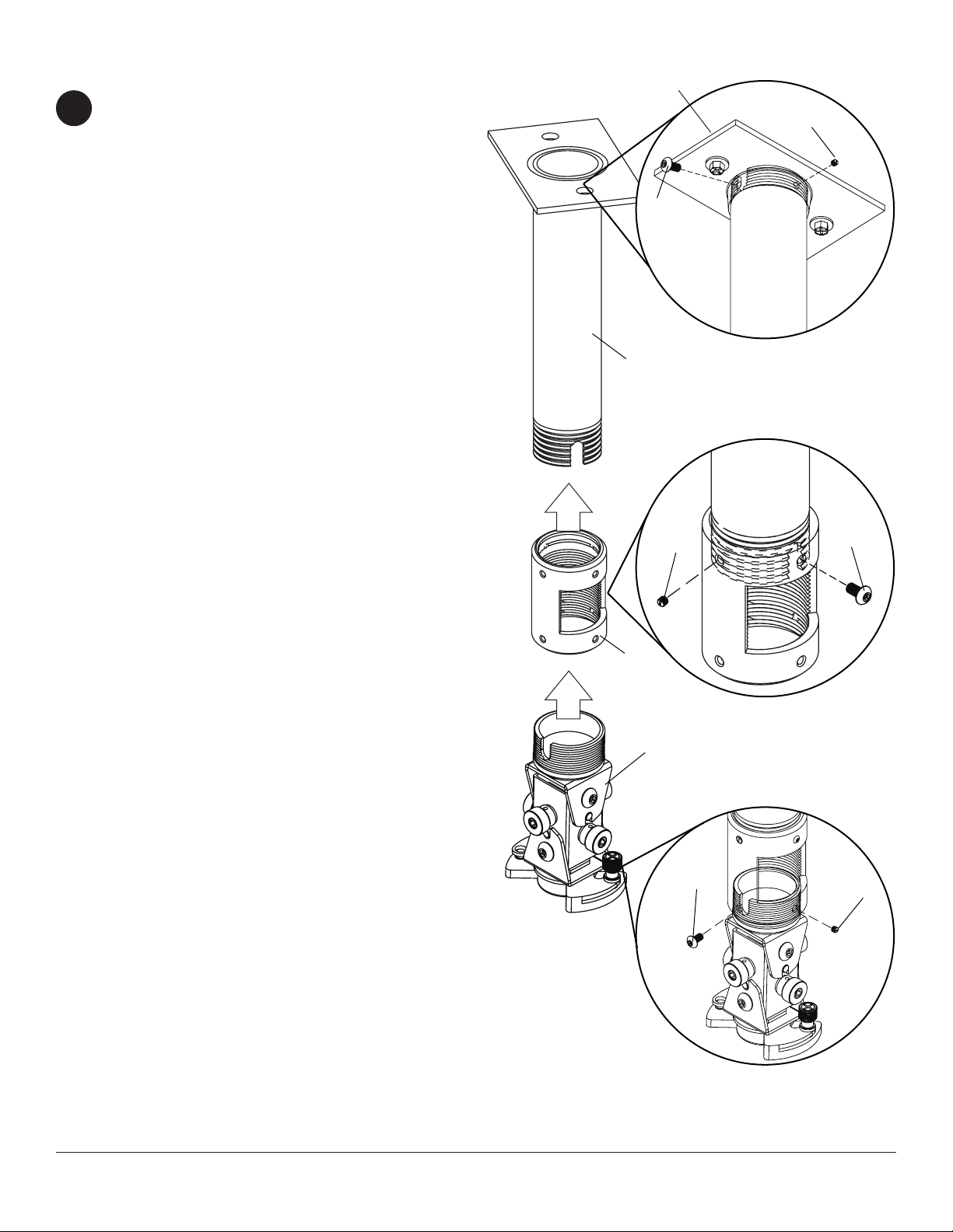
Extension Column Installation
Handthreadextensioncolumnintoceilingplace(J).
Alignnotchofextensioncolumnwithoneofthefour
holesinceilingplate(J)andsecurewithan
M5x10mmsocketpinscrew(S)usingallenwrench
(E)asshownindetail2.
Handthreadcolumnconnector(I)ontoextension
column.Alignslotinextensioncolumnwithoneof
thetopholesofthecolumnconnector(I).Insert
andtightenone#10-32x3/8"socketpinscrew(P)
throughcolumnconnector(I)intoslotofextension
columnusing4mmsecurityallenwrench(O)as
shownindetail3.
Handthreadprojectormountassembly(H)into
columnconnector(I).Alignslotofprojectormount
assembly(H)withoneofthebottomholesincolumn
connector(I).Insertandtightenone#10-32x3/8"
socketpinscrew(P)throughcolumnconnectorinto
projectormountassemblyusing4mmsecurityallen
wrench(E)asshownindetail4.
NOTE:Slottedsetscrews(N)areusedtojam
againstthethreadsofeachconnectingjointto
preventanyexcessmovement.Donotovertighten
screw.Overtighteningscrewwilldamagethreads
makingitdifculttoseparatecomponents.
3
g. 3.1
DETAIL 2
DETAIL 3
DETAIL 4
P
N
N
P
I
H
EXTENSION
COLUMN(SOLD
SEPARATELY)
(ULLISTEDEXT
ORADJSERIES)
S
N
J
7 of 8
ISSUED: 09-15-11 SHEET #:125-9244-1
FRONTOF
PROJECTOR
4
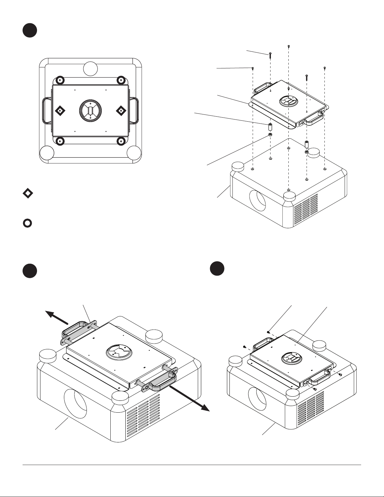
Handlescanbepulledoutforadditionalleverageas
shownbelow.
5
Handlescanbesecuredtoadapterassembly
(A)usingfourM5x10mmsocketpinserrated
washerheadscrews(C)asshownbelow.
6
FRONTOF
PROJECTOR
FRONTOF
PROJECTOR
FRONTOFPROJECTOR
M4X40MMSOCKETPINSERRATED
WASHERHEADSCREW(D),WITH
SPACERS(F AND G)
M4X12MMSOCKETPINSERRATED
WASHERHEADSCREW(B)
A
B
C
D
F
G
A
HANDLE
Fastenadapterassembly(A)tobottomofprojectorusingtwoM4x40mmsocketpinserratedwasherhead
screws(D)withspacers(F and G),andfourM4x12mmsocketpinserratedwasherheadscrews(B)in
orientationasshownbelow.
8 of 8
ISSUED: 09-15-11 SHEET #:125-9244-1
©2011,PeerlessIndustries,Inc.Allrightsreserved.
Allotherbrandandproductnamesaretrademarksorregisteredtrademarksoftheirrespectiveowners.
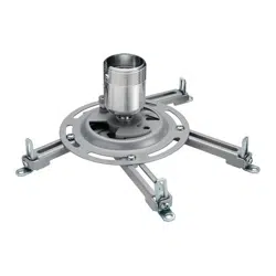
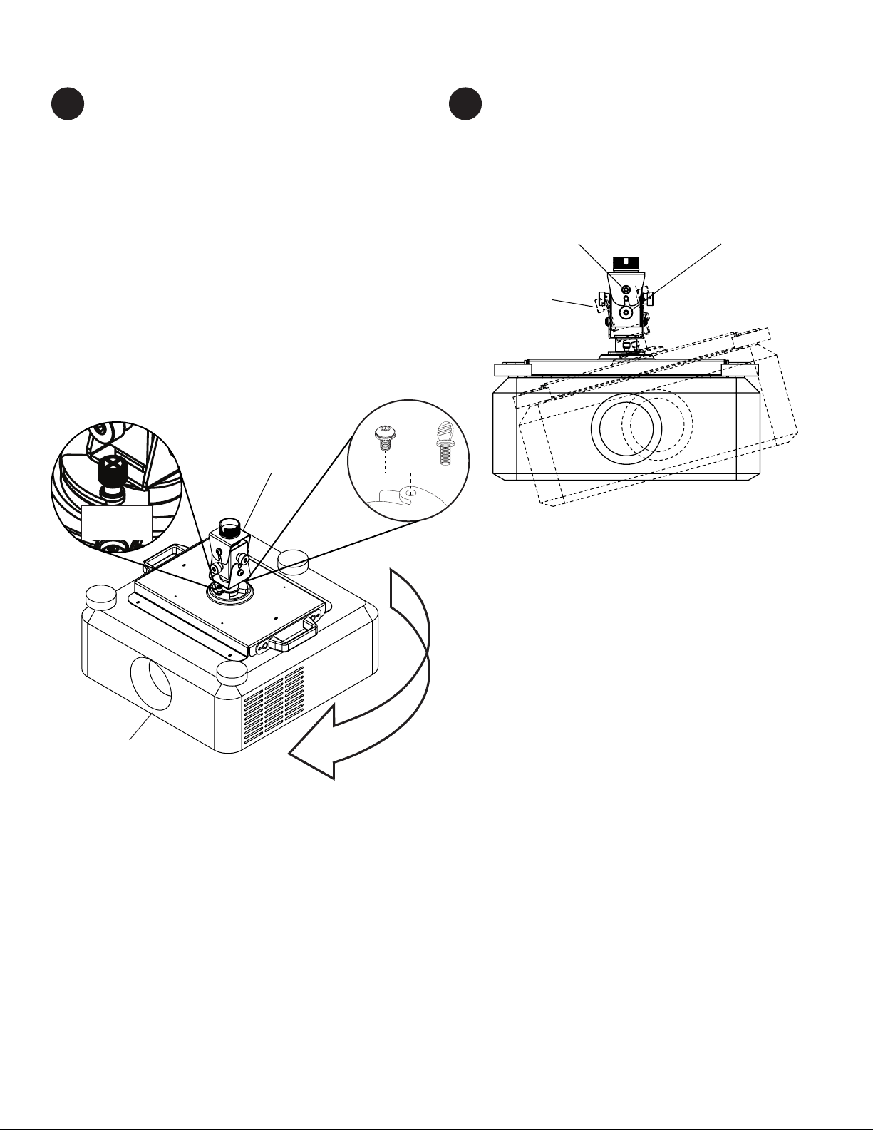
Attaching Adapter Plate to Projector Mount
Attachprojectortoprojectormountassembly(H)
byinsertingthemountintotheadapterplateand
twistinguntiltheadapterplatewillnolongerturn.
Thespringloadedcaptivescrewshouldlineupwith
acorrespondingholeontheadapterplate.Push
downandtightenthespringloadedcaptivescrewto
securetheadapterplatetothemount.Ifnotusing
theoptionalsecurityfeature,fastenthumbscrew(L)
intheholeoppositethespringloadedcaptivescrew.
OPTIONAL:ForArmorLock™security,insert
#10-32x3/8"serratedwasherheadscrew(M)in
theholeoppositethespringloadedcaptivescrew.
Tightenwith4mmsecurityallenwrench(E).This
willpreventtheprojectorfrombeingremoved.
Useknobstoadjustprojectormountrollandpitch.
Knobsalsomaybeadjustedusingallenwrenches
(E,R).
Tightensocketpinscrewusingallenwrench(E)to
lockrollandpitchposition.
7 8
CAPTIVE
SCREW
H
PROJECTOR
ROLL
ADJUSTMENT
KNOB
PITCH
ADJUSTMENT
KNOB
SOCKET
PIN SCREW
L
M