
Wall Range Hood
User Manual
and
Installation Instructions
IMPORTANT SAFETY INSTRUCTIONS
Carefully read the important information
regarding installation, safety and maintenance.
Keep these instructions for future reference.
MAAN17034SS-02
2023-07-12
— 2 —
INSTALLERS - Start Here
Safety Instructions are on pages 4 and 5 and
Installation Instructions are on pages 9 to 15.
Please perform these steps:
1. Read the safety instructions.
2. Read all instructions in the Installation section of
this manual BEFORE installing the range hood.
3. Remove all packing materials.
4. When nished, make sure to leave these instructions with the consumer.
5. Installation is to be done by a qualied technician only. However, the
ultimate responsibility for proper installation falls to the owner.
6.
Product failure due to improper installation is not covered under the Warranty.
CONSUMERS - Start Here
Safety Instructions are on pages 4 and 5 and Operating Instructions are
on pages 16 to 19.
Please perform these steps:
1. Read the safety instructions.
2. Read all instructions in the manual BEFORE operating the range hood.
3. Remove all packing materials.
4. Installation is to be done by a qualied technician only. However, the
ultimate responsibility for proper installation falls to the owner.
5.
Product failure due to improper installation is not covered under the Warranty.
Before You Begin
Hardware Note: For safety reasons, range hood mounting screws
and anchors will not be included due to the variation of cabinetry
constructions and wall material. Please consult your installation
specialist regarding the optimal type of mounting screws and wall
anchors to suit your home’s construction.

— 3 —
Before You Begin ............................................................................................................................... 2
Table of Contents .............................................................................................................................. 3
Important Safety Information ............................................................................................................ 4
Included Parts ................................................................................................................................... 6
Range Hood Dimensions .................................................................................................................. 7
Specications .................................................................................................................................... 7
Mounting Brackets ............................................................................................................................ 8
Installation ......................................................................................................................................... 9
Step 1 - Read the Safety Instructions ............................................................................................ 9
Step 2 - Unpack Range Hood and Prepare Tools .......................................................................... 9
Step 3 - Plan Desired Location ...................................................................................................... 9
Step 4 - Test Unit Functions .......................................................................................................... 9
Step 5 - Venting Installation Guidelines ....................................................................................... 10
Step 6 - Preparations ................................................................................................................... 12
Step 7 - Installing the Hood Mounting Bracket ........................................................................... 12
Step 8 - Installing the Upper Chimney Bracket ........................................................................... 12
Step 9 - Venting ........................................................................................................................... 13
Step 10 - Mount Range Hood onto Wall ...................................................................................... 13
Step 11 - Connect Ductwork ....................................................................................................... 13
Step 12 - Plug-in .......................................................................................................................... 13
Step 13 - Install Chimney ............................................................................................................. 14
Step 14 - Install Oil Cup ............................................................................................................... 15
Step 15 - Install Filters ................................................................................................................. 15
Operation ........................................................................................................................................ 16
Power Settings ............................................................................................................................. 16
Lights ........................................................................................................................................... 16
Timer ............................................................................................................................................ 16
Maintenance.................................................................................................................................... 17
Cleaning Filters ............................................................................................................................ 17
Cleaning Oil Cup .......................................................................................................................... 17
Replacing the Light ...................................................................................................................... 17
Troubleshooting............................................................................................................................... 18
Use and Care Information ............................................................................................................... 19
Table of Contents

— 4 —
Important Safety Information
• Theinstallationinthismanualisintended
for qualied installers, service technicians or
persons with a similar qualied background.
Installation must be done by qualied
professionals and in accordance with all
applicable codes and standards, including
re-rated construction.
•
The range hood may have very sharp
edges; please wear protective gloves if it is
necessary to remove any parts for installing,
cleaning or servicing.
•
Activating any switch to ON position before
completing installation may cause damage or
electric shock.
• Duetothesizeofthisrangehood,atwo-
person installation is recommended.
To reduce the risk of fire, electric shock, or
injury to persons:
• Forgeneralventilatinguseonly.DO NOT use
toexhausthazardousorexplosivematerials
and vapors.
• WARNING: To Reduce The Risk Of Fire Or
Electric Shock, Do Not Use This Fan With Any
Solid-State Speed Control Device.
• Thecombustionairowneededforsafe
operation of fuel-burning equipment may be
affected by this unit’s operation. Follow the
heating equipment manufacturer’s guideline
and safety standards such as those published
by the National Fire Protection Association
(NFPA), and the American Society of Heating,
Refrigeration and Air Conditioning Engineers
(ASHRAE), and other local code authorities.
• Beforeservicingorcleaningtheunit,switch
power off at service panel and lock the service
disconnecting means to prevent power from
being switched on accidentally. When the
service disconnecting means cannot be
locked, securely fasten a prominent warning
device, such as a tag, to the service panel.
• Cleangrease-ladensurfacesfrequently.To
optimizeperformanceandtodisperseair
properly, make sure to vent air outside. DO
NOT vent exhaust into spaces between walls,
crawl spaces, ceilings, attics or garages.
•
Ducted fans MUST always be vented to
the outdoors.
• ThisunitMUSTbegroundedandusedwith
metal ductwork only.
• Sufcientairisneededforpropercombustion
and exhausting of gases through the duct to
prevent back drafting.
• Whencuttingordrillingintowallorceiling,be
careful not to damage electrical wiring or other
hidden utilities.
• Allelectricalwiringmustbeproperlyinstalled,
insulated and grounded.
•
Old ductwork should be cleaned or replaced
if necessary to avoid the possibility of a
grease re.
•
Check all joints on ductwork to ensure
proper connection; all joints should be
properly taped using a certied aluminum
or foil tape.
• Usethisunitonlyinthemannerintended
by the manufacturer. If you have questions,
contact the vendor.
READ AND SAVE THESE
INSTRUCTIONS
READ ALL INSTRUCTIONS BEFORE USE
Read and follow all instructions before using the range hood to prevent the risk of re, electric shock,
personal injury, or damage when using the range hood or appliances with the range hood. This guide
does not cover all possible conditions that may occur. Always contact your service technician or
manufacturer about problems that you do not understand.

— 5 —
Important Safety Information
WARNING: TO REDUCE RISK OF A RANGE
TOP GREASE FIRE:
a) Never leave surface units unattended at high
settings. Boilovers cause smoking and greasy
spillovers that may ignite. Heat oils slowly on
low or medium settings.
b) Always turn range hood ON when cooking at
highheatorwhenambéingfood(i.e.Crepes
Suzette,CherriesJubilee,etc.).
c)
Clean ventilating fans frequently. Grease should
not be allowed to accumulate on fan or lter.
Before servicing or cleaning unit, unplug and
disconnect the hood from the power supply.
d)Useproperpansize.Alwaysusecookware
appropriateforthesizeofthesurfaceelement.
WARNING: TO REDUCE RISK OF INJURY TO
PERSONS IN THE EVENT OF A RANGE TOP
GREASE FIRE, OBSERVE THE FOLLOWING *
a) S
MOTHER FLAMES with a close-tting
lid, cookie sheet, or metal tray, then turn
off the burner. BE CAREFUL TO PREVENT
BURNS.Iftheamesdonotgoout
immediately, EVACUATE AND CALL THE
FIRE DEPARTMENT.
b) NEVER PICK UP A FLAMING PAN - You may
be burned.
c) DO NOT USE WATER, including wet dishcloths
or towels - a violent steam explosion will result.
d) Use an extinguisher ONLY if:
1) You know you have a Class A, B, C
extinguisher, and you already know how to
operate it.
2) The re is small and contained in the area
where it is started.
3) The re department is being called.
4)
You can ght the re with your back to an exit.
* Based on “Kitchen Fire Safety Tips”
published by NFPA
To reduce the risk of injury to persons in the
event of a gas leaks:
• Extinguishanyopename.
•
DO NOT turn on the lights or any type of appliance.
• Openalldoorsandwindowstodispersethe
gas. If you still smell gas, call the gas company
and re department.
Your safety and the safety of others is very
important. We have provided many important
safety messages in this manual and on your
appliance. Always read and obey all safety
messages. All safety messages outline any
potentialhazards,howtoreducethechanceof
injury, and possible risks if the instructions are not
followed.
READ AND SAVE THESE
INSTRUCTIONS
— 6 —
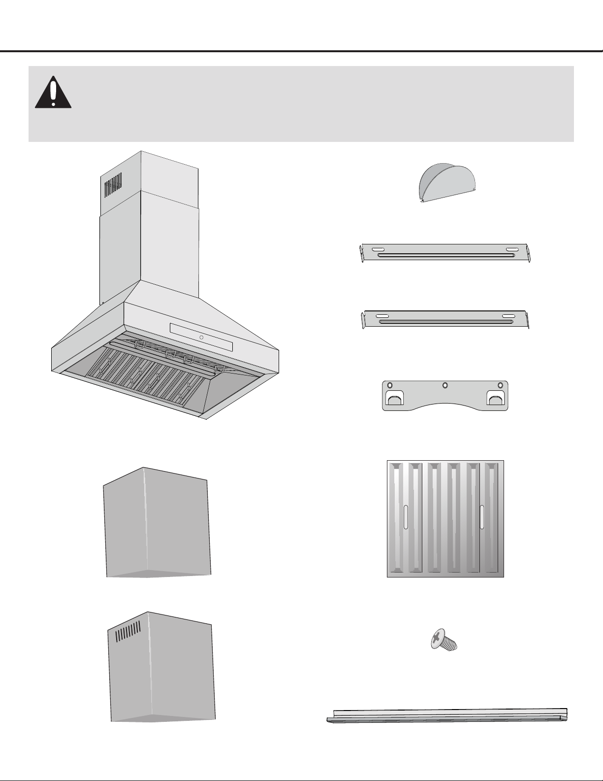
Included Parts
Main Housing
4 Filters
Upper Chimney
Lower Chimney
Upper Chimney Bracket
Hardware Note: For safety reasons, range hood mounting screws and anchors will
not be included due to the variation of cabinetry constructions and wall material.
Please consult your installation specialist regarding the optimal type of mounting
screws and wall anchors to suit your home’s construction.
2 + 2 Screw
Lower Chimney Bracket
Hood Mounting Bracket
Damperap
2 Oil Cup
— 7 —
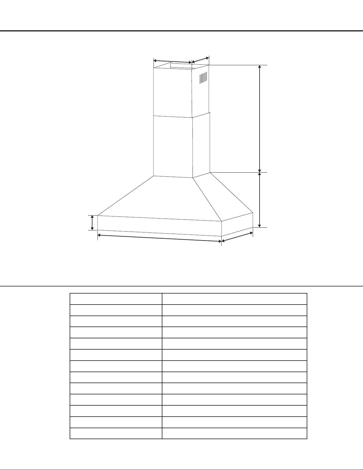
Range Hood Dimensions
Specifications
Body Design Stainless Steel
Power Rating 120V/60Hz(cETLusCertied)
Total Input Power 276 W (270 W + 6 W)
Motor Input Power 270 W
Amperage 2.2 A
Speed Control Levels 9 Speeds
Interference Protection Radio Frequency Interference Protected
Motors Single Motor
Controls LCD electronic touch control panel
Filtration StainlessSteelBafeFilter
Lighting 1 × 6 W LED
Light Intensity Levels 1
VentingSize Top, 6 inches (153 mm) round
29.3” (74.5 cm) or 35.2” (89.5 cm)
19.6”
(50 cm)
3.9”
(10 cm)
13.7”
(35 cm)
15.4” - 29.2”
(39.3 - 74.3 cm)
11.1”
(28.3 cm)
11”
(28 cm)
— 8 —
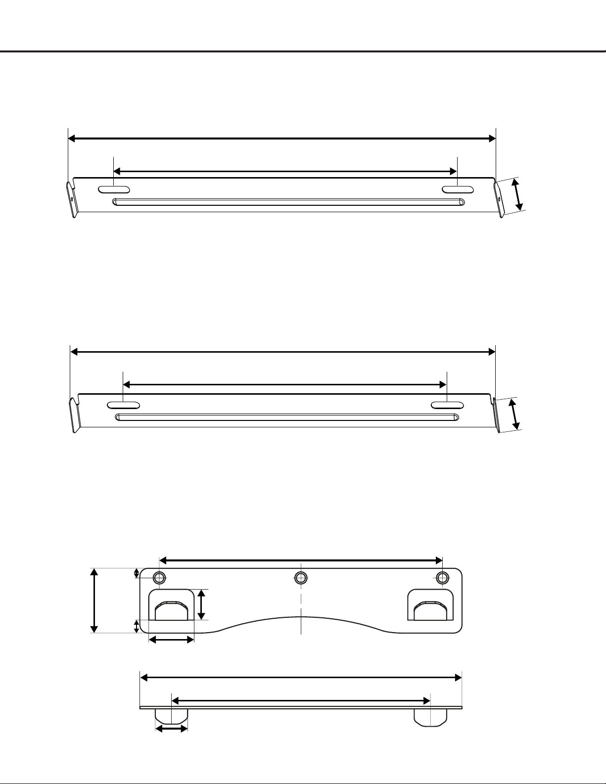
Mounting Brackets
Upper Chimney Bracket
Lower Chimney Bracket
Mounting Bracket Hook
6.8” (17.5 cm)
1.5”
(4 cm)
1.1” (2.8 cm)
0.75”
(1.9 cm)
0.75” (2 cm)
7.8” (19.9 cm)
6.3” (16 cm)
0.2”
(0.6 cm)
0.3”
(0.8 cm)
10.3” (26.3 cm)
7.8” (20 cm)
1”
(2.5 cm)
1”
(2.5 cm)
10.7” (27.4 cm)
9.25” (23.5 cm)
6.8” (17.5 cm)
1.5”
(4 cm)
1.1” (2.8 cm)
0.75”
(1.9 cm)
0.75” (2 cm)
7.8” (19.9 cm)
6.3” (16 cm)
0.2”
(0.6 cm)
0.3”
(0.8 cm)
10.3” (26.3 cm)
7.8” (20 cm)
1”
(2.5 cm)
1”
(2.5 cm)
10.7” (27.4 cm)
9.25” (23.5 cm)
6.8” (17.5 cm)
1.5”
(4 cm)
1.1” (2.8 cm)
0.75”
(1.9 cm)
0.75” (2 cm)
7.8” (19.9 cm)
6.3” (16 cm)
0.2”
(0.6 cm)
0.3”
(0.8 cm)
10.3” (26.3 cm)
7.8” (20 cm)
1”
(2.5 cm)
1”
(2.5 cm)
10.7” (27.4 cm)
9.25” (23.5 cm)

— 9 —
STEP 1
Read the Safety Instructions
• It is very important to read the safety instructions on pages 4 and 5.
IMPORTANT: It is the installer’s responsibility to comply with installation clearances.
STEP 2
Unpack Range Hood and Prepare Tools
• Carefully unpack the range hood and parts. Make sure all parts are included as shown on page 6.
• DO NOT remove the protective lm covering the appliance until the installation is fully completed.
• Consult a qualied and trained installer or check local codes for makeup air requirement, if any.
STEP 3
Plan Desired Location
• Plan a desirable location that ts all requirements in the Safety and Installation sections of this manual. Plan where
and how the ductwork will be installed.
• A straight or short duct run will allow the unit to perform most efciently. Long duct runs, elbows and transitions
will reduce the performance of the unit. Each elbow is equivalent to 5 to 10 feet (1.5 m to 3 m) of straight run.
Propersizeductworkshouldbe6in.(15.3cm)indiameter.
• To reach a 9-foot (2.74 m) ceiling make sure hood is installed 30 inches (76.2 cm) from cooking surface. If
you have a ceiling greater than 9 ft (2.74 m), please visit anconahome.com to order a chimney extension.
• If ductwork is already installed: ensure ductwork is free from debris and measures 6 in.
(15.3 cm)
(1 in. (2.5 cm)
reducers may be used but more than 1 in. (2.5 cm) will overwork the motor and the unit will not function properly).
STEP 4
Test Unit Functions
• Plug the unit in and test all of the functions before installing.
• Placetherangehoodonaat,stablesurface.Connecttherangehoodtoadesignatedstandardoutlet(120-Volt,60Hz,
AC only) and turn on the range hood. Verify all operations of the range hood by referring to
Range Hood Operations.
• Turn power On in control panel.
• Check all lights and fan operations.
WARNINGS:
• PleasemakesuretoreadALLsafetyinstructionsonpages4and5.
• Usetwoormorepeopletomoveandinstallrangehood.
• Failuretofollowtheseinstructionscanresultinseriousinjury.
Installation
— 10 —
Installation
STEP 5
Venting Installation Guidelines
• The following steps are for exterior ventilation.
Height and Clearance
IMPORTANT:
•
Vent system must terminate to the outside (roof or side wall).
• DONOT
terminate the vent system in an attic or other
enclosed area.
• DONOTuse4in.(10.2cm)laundry-typewallcaps.
• Usemetal/aluminumventonly.Arigidmetal/aluminum
vent is recommended.
• DONOTuseaplasticvent.
• Alwayskeeptheductcleantoensureproperairflow.
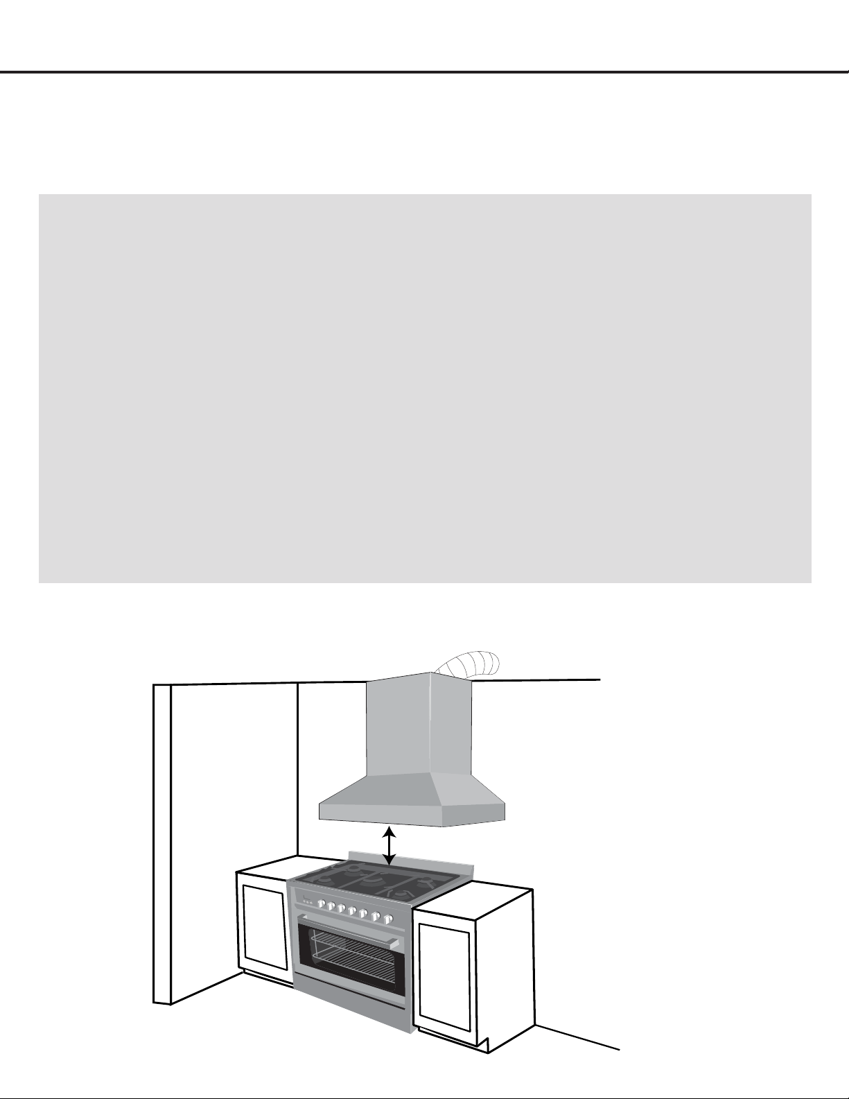
• Calculatethefollowingfiguresbeforeinstallation:
1. Distance from the floor to the ceiling
2. Distance between the floor and the countertop/stove
3.
A distance of 24 in. to 30 in. (61 cm to 76.2 cm) is
recommended between stove top and the bottom of
range hood. 30 in. (76.2 cm) minimum is required for
gas stove tops.
4. Height of hood and duct cover.
For the most efficient and quiet operation:
• Itisrecommendedthattherangehoodbevented
vertically through the roof through 6 in. (15.3 cm) or
bigger round metal/aluminum vent work.
• Thesizeoftheventshouldbeuniform.
• Usenomorethanthree90°elbows.
•
Make sure there is a minimum of 24 in. (61 cm) of
straight vent between the elbows if more than one
elbow is used.
• DONOTinstalltwoelbowstogether.
•
The length of vent system and number of elbows should be
kept to a minimum to provide efficient performance.
• Theventsystemmusthaveadamper.Ifrooforwall
cap has a damper, you may remove damper flaps from
damper to increase air flow.
• Onlyoneflangeisneededintheairductsystem,either
on top of the motor or outside.
•
Use silver tape or duct tape to seal all joints in the
vent system.
•
Use caulking to seal exterior wall or roof opening
around the cap.
24 in. (610 mm) Min / 30 in. (762 mm) Max
— 11 —
IMPORTANT:
•
A minimum of 6 in. (15.3 cm) round or 10 × 3 -1/4 in.
(25.4
cm × 8.3 cm)
rectangular duct (purchased separately) must
be used to maintain maximum airflow efficiency.
• Alwaysuserigidtypemetal/aluminumductsifavailableto
maximizeairflowwhenconnectingtoprovidedduct.
• PleaseuseDuctRunCalculationbelowtocompute
total available duct run when using elbows, transitions
and caps.
• ALWAYS,whenpossible,reducethenumberor
transitions and turns. If long duct run is required,
increaseductsizefrom6in.(15.3cm)to7in.(17.7
cm) or 8 in. (20.3 cm). If a reducer is used, install a
long reducer instead of a pancake reducer. Reducing
ductsizewillrestrictairflowanddecreaseairflow,thus
reduceductsizeasfarawayfromopeningaspossible.
• Ifturnsortransitionsarerequired,installasfaraway
from opening and as far apart, between two (2), as
possible.
• Minimummountheightbetweenstovetoptohood
bottom should be no less than 24-inch (61 cm) for
electric cook tops and minimum of 30-inch (76.2 cm)
for gas stove tops and no higher than 30-inch (76.2 cm)
for electric cook tops.
• Itisimportanttoinstallthehoodatthepropermounting
height. Hoods mounted too low could result in heat
damageandfirehazard;whilehoodsmountedtoohigh
may be hard to reach and will lose its performance and
efficiency.
• Ifavailable,alsorefertostovetopmanufacturer’s
height clearance requirements and recommended
hood mounting height above range.
Installation
• This range hood is factory set for venting through the roof or wall.
• Ventworkcanterminateeitherthroughtherooforwall.Toventthroughawall,a90°elbowisneeded.
IMPORTANT:
• NEVER exhaust air or terminate duct work into spaces between walls, crawl spaces, ceiling, attics or
garages. All exhaust must be ducted to the outside.
• Use metal/aluminum duct work only.
• Fasten all connections with sheet metal screws and tape all joints with certied Silver Tape or Duct Tape.
• Use caulking to seal exterior wall or roof opening around the cap.
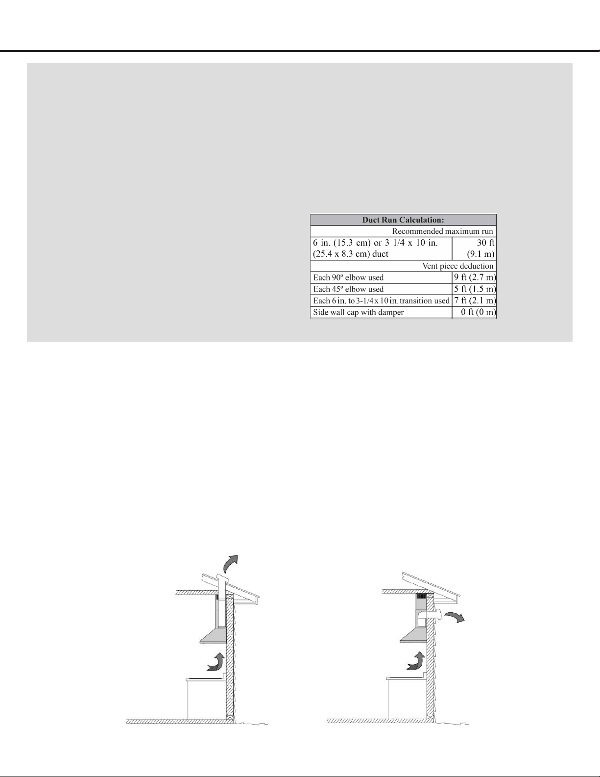
TOP VENTING
ROOF EXHAUST
TOP VENTING
WALL EXHAUST
Duct Run
Calculation
example:
One roof cap, two
90º elbows, and
one 45º elbow use.
0ft + 9ft + 9ft + 5ft
= 23ft used.
Deduct 23ft from
30ft, 7ft maximum
available for
straight duct run.
— 12 —
Installation
STEP 6
Preparations
NOTE: To avoid damage to your hood, prevent debris from entering the vent opening.
• Determine and mark the center line on the ceiling or wall where the range hood will be installed.
• Make sure there is proper clearance within the ceiling or wall for exhaust vent.
• Duetotheweightandsizeofthisunit,pleasemakesurethatthesupportsystemorframeworkbeingusedisstableand
secure in the ceiling or wall.
• Put a thick, protective covering over countertop, cooktop or range to protect from damage or dirt.
• Removeanyhazardousobjectsaroundtheareawheninstalling.
CAUTION
If moving the cooking range is necessary to install the hood, turn OFF the power on an electric range at the main
electrical box. SHUT OFF THE GAS BEFORE MOVING A GAS RANGE.
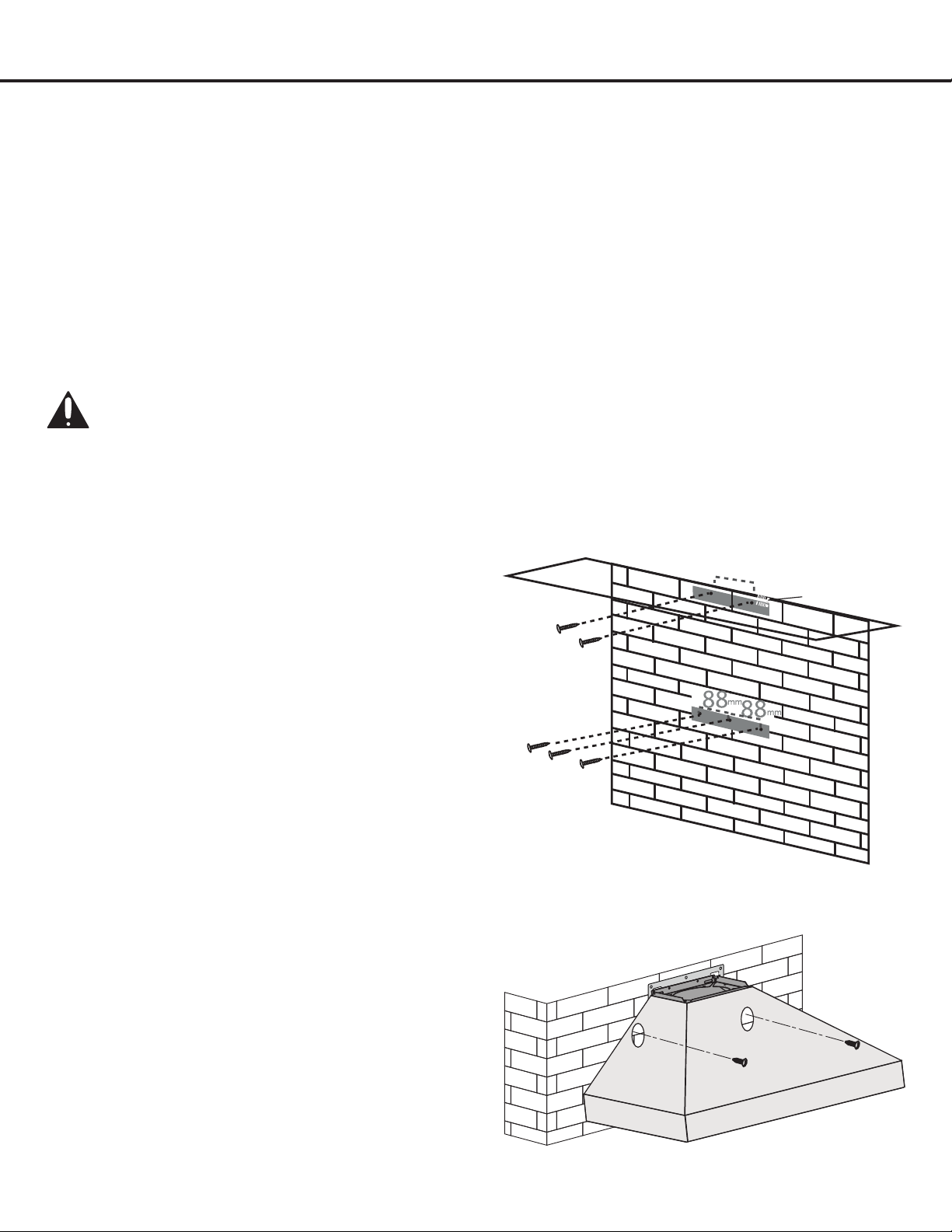
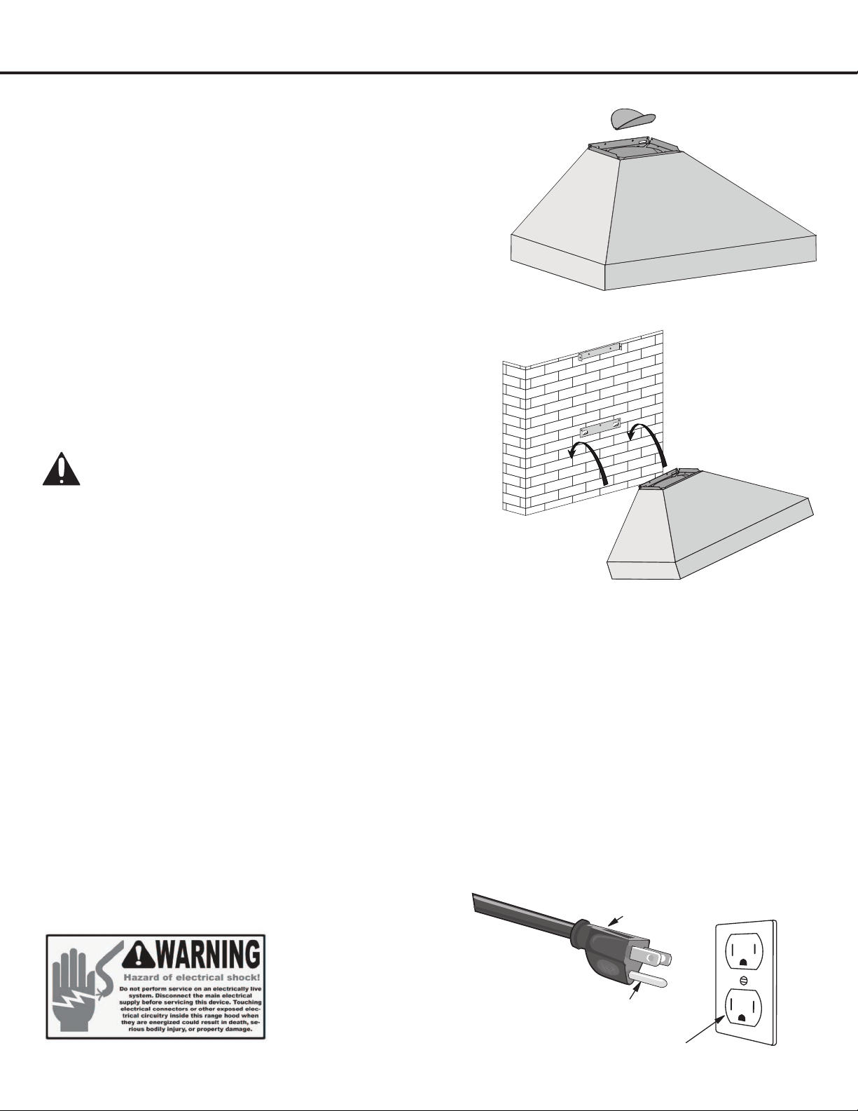
STEP 7
Installing the Hood Mounting Bracket
• Use a pencil to mark on the wall the desired placement of
the range hood mounting screws.
• The range hood will be installed on top of this bracket (see
Figure 1).
• Using references in Height & Clearance on Page 10 and
Measurements and Diagrams on Page 7, drill 3 holes that
will be used to x the lower mounting bracket.
STEP 8
Installing the Upper Chimney Bracket
• Drilltwoholesaccordingtothesizeoftheuppermounting
bracket.Toinstallchimneyushtotheceiling,theupper
mounting bracket orice should be positioned 2.1 cm from the
ceiling if hooking chimney to bracket (see Figure 6-1), or 2.6 cm
from the ceiling if screwing bracket to chimney (see Figure 6-2).
• Screw upper and hood mounting brackets in tightly.
• Optional step: For extra support, drill 2 additional holes
aligned to hood’s pre-drilled holes, to mount the hood onto
the wall (see Figure 2).
2.1 or 2.6 cm
235 mm
Figure 1
Figure 2
— 13 —
Installation
STEP 10
Mount Range Hood onto Wall
• Hang the range hood on the hooks of the hood mounting
bracket (see Figure 4).
• Screw the range hood to the wall.
CAUTION - Make certain the range hood is secure
before releasing!
STEP 11
Connect Ductwork
• Attach ductwork to damper. Secure the ductwork with duct tape to make sure joints are secure and air- tight.
• Donotinstalltheducttapetootightlyasthismaypreventthedamperapsfromopeningwhichwilloverworkthemotor
and cause improper functioning of the unit.
• Fasten all connections with sheet metal screws and tape all joints with certied aluminum or foil tape. Use caulking to
seal exterior wall or roof opening around the cap.
STEP 9
Venting
• Fixthedamperaponthetopventofthehood(seeFigure3).
• If ventilation system is equipped with an external air duct with a
different diameter, apply a reduction tting. However, for maximum
performance and safety, a 6 in. round ducting is recommended.
STEP 12
Plug-in
• Connect3-pronggroundedplugintoa3-pronggroundedoutlet(120V,60Hz).Placetheoutletatamaximumdistance
of 33-1/2 in. (851 mm) from where the cord exits on the hood.
• SEE IMPORTANT INSTRUCTIONS ON NEXT PAGE.
3-Pronged Plug
Ground Plug
3-Prong Outlet
Figure 3
Figure 4
— 14 —
IMPORTANT:
• Observeallgoverningcodesandordinances.
• It is the customer’s responsibility to contact a qualified electrical installer.
• Ifcodespermitandaseparategroundwireisused,itisrecommendedthataqualifiedelectriciandeterminethat
thegroundpathisadequate.A120-Volt,60Hz,AC-only,fusedelectricalsupplyisrequiredonaseparate15-amp
circuit, fused on both sides of the line.
• DONOTgroundtoagaspipe.
• Checkwithaqualifiedelectricianifyouarenotsurethattherangehoodisproperlygrounded.
• DONOThaveafuseintheneutralorgroundcircuit.
IMPORTANT: Save this Installation Guide for electrical inspector’s use.
GROUNDING INSTRUCTIONS:
• Thisappliancemustbegrounded.Intheeventofanelectricalshort-circuit,groundingreducestheriskofelectric
shock by providing an escape wire for the electric current.
• Thisapplianceisequippedwithacordhavingagroundingwirewithagroundingplug.Theplugmustbeplugged
into an outlet that is properly installed and grounded.
WARNING: Improper grounding can result in a risk of electric shock.
• Consultaqualifiedelectricianifthegroundinginstructionsarenotcompletelyunderstood,orifdoubtexistsasto
whether the appliance is properly grounded. DO NOT use an extension cord. If the power supply cord is too short,
have a qualified electrician install an outlet near the appliance.
Installation
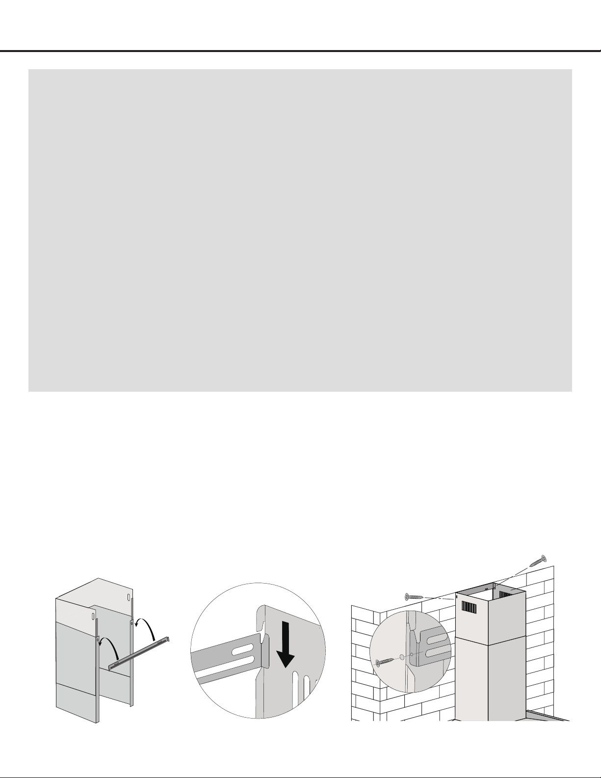
STEP 13
Install Chimney
• Place chimney on top of the main housing.
• Remove the protective coating from the upper chimney. Carefully slide the upper chimney down into the lower chimney.
Make sure upper chimney is moving freely.
• Hook lower chimney bracket to lower chimney, then screw the lower chimney bracket onto wall (see Figure 5).
• Either hook the bracket to the upper chimney by matching the side lock (see Figure 6-1),
OR
screw the upper chimney to the upper mounting bracket (see Figure 6-2).
Figure 5 Figure 6-1 Figure 6-2
— 15 —
Installation
Figure 8
Figure 9 Figure 10
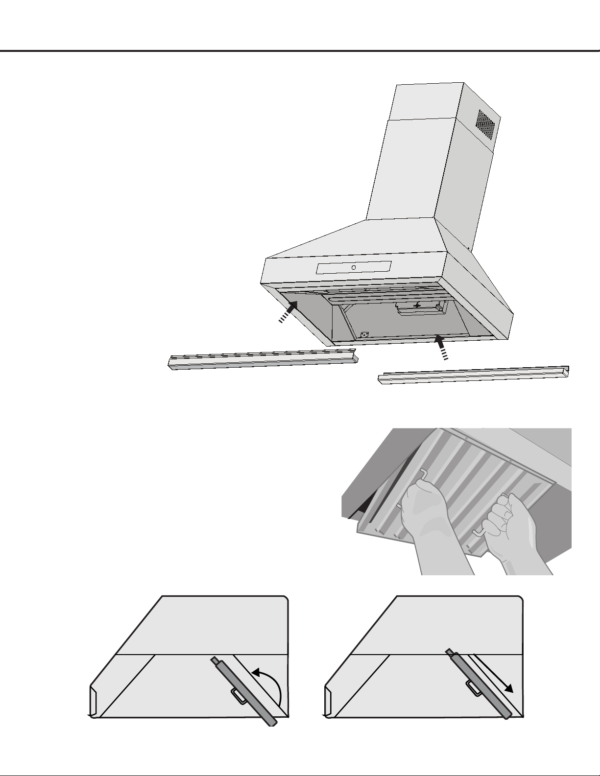
STEP 15
Install Filters
• Angle and insert one end of the lter into the upper channel of the
range hood (Figure 8).
• Raise the other end towards the inside of range hood, rotate and
insert in the bottom end of opening (Figure 9 and 10).
• Release the handle once the lter ts into a resting position.
• Repeat to install all lters.
STEP 14
Install Oil Cup
Your range hood includes a unique oil cup which collects the oil that is
deposited on the grease lters. When the oil cup is about 1/3 full, the
oil cup needs to be cleaned.
• Discard the oil before cleaning/washing the cup.
• Ensure the cup has been cleaned and dried before reattaching to
the hood.
• Angle and insert the oil cup on the rear end of the unit, and
push into place (see Figure 7).
Figure 7

— 16 —
Operation
DecreaseTime delay shut-off IncreaseDigital display Light
Power Settings
u
Press digital display button to turn power on and off.
v
While unit is operating, press decrease button to reduce
speed one level.
w
While unit is operating, press increase button to
increase speed one level.
Lights
u
Press once to turn the lights on, press again to turn
the lights off.
Timer
u
On stand-by or during operation, press time delay
shut-off button for 3 seconds and the digital display
will blink. Delay power-off time can be set with
increase and decrease controls, from 1 minute to 9
minutes; press the delay button again to save the
setting. If no buttons are pressed after 10 seconds,
the settings will be saved automatically.
v
When the motor is working and the delay setting
is saved, the setting can still be adjusted, and the
display window will show countdown time.
w
When the motor is not working, the delay time can
be set but without countdown function. The delay
time will turn to countdown time when the motor is
working.
— 17 —
Maintenance
Cleaning Filters
IMPORTANT: Drain oil from baffles, spacers, filters, oil tunnels, oil containers before oil and residue overflow!
• Removeallbafes,spacers,lters,greasetray,andoilcontainersanddiscardoilandresidue.
• Washwithwarmsoapywater.NOTE:Stainlesssteelbafes,spacersandoiltunnelaretoprackdishwashersafe.
• Dry thoroughly before replacing and follow directions for installation in reverse.
• Filters should be cleaned after every 30 hours of use.
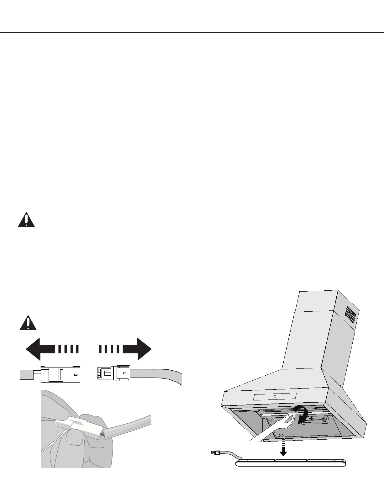
• Should lters wear out due to age and prolonged use, replace with a new lter.
u
Make sure the range hood is unplugged or turn OFF
breaker.
v
Remove lters. Reach into interior of range hood
until reaching clip located on the side of the light.
Gentlysqueezeandpushdownuntillightpopsout
from its location, pull out the LED light and unplug it.
CAUTION: LIGHT MAY BE HOT, PLEASE TAKE
OUT THE LIGHT WHEN THE LIGHT IS
COMPLETELY COOL!
w
Replace with appropriate LED light. Please contact
Ancona customer service for replacement. Plug in
new light and push back into light panel.
x
Turn ON breaker and range hood to test for
operation.
Replacing the Light
IMPORTANT:
ALWAYS SWITCH OFF THE ELECTRICITY SUPPLY AT THE MAIN PANEL BEFORE CARRYING OUT ANY OPERATION
ON THE APPLIANCE.
Figure 12
Cleaning Oil Cup
• Remove the oil cup, by slightly pulling the oil cup forwards to release it from the range hood.
• Discard the oil before cleaning/washing the cup.
• Ensure the cup has been cleaned and dried before reattaching to the hood.
Figure 11
— 18 —
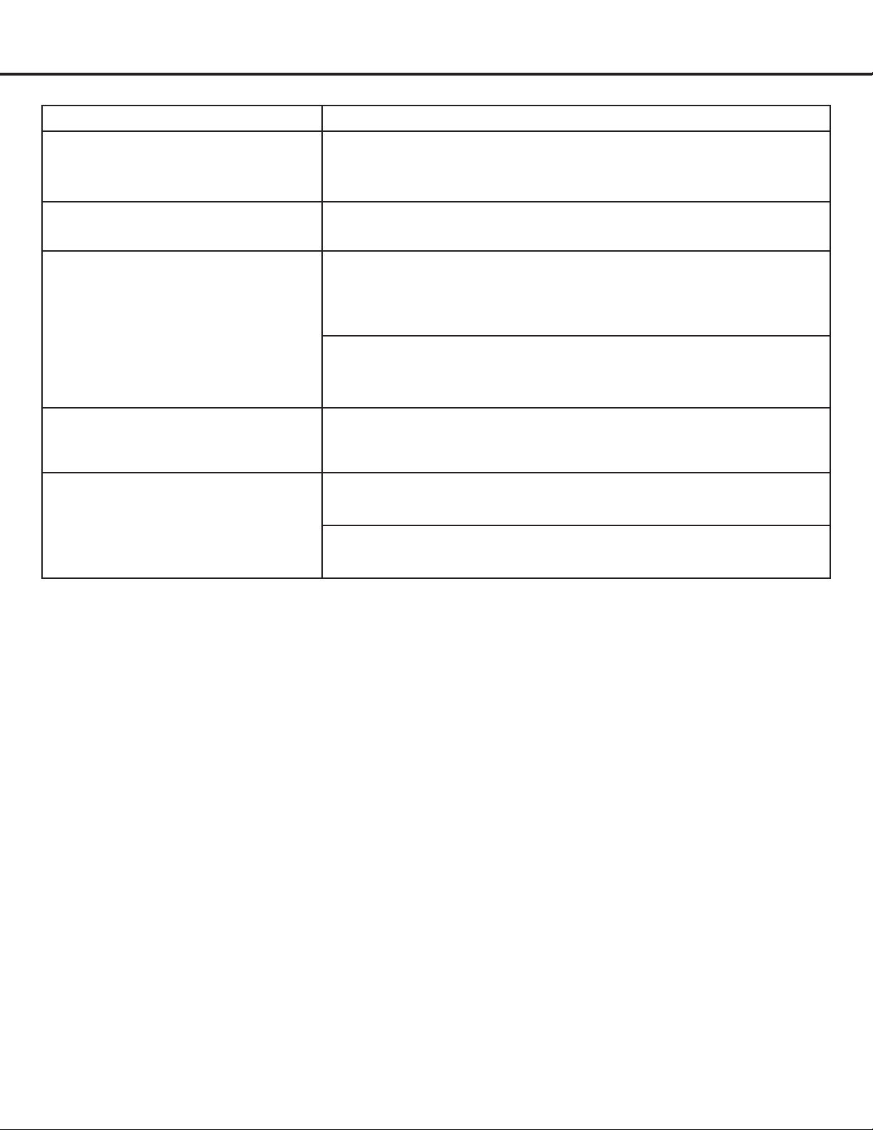
Troubleshooting
Problem Possible Cause
If the range hood or LED light does
not operate after installation:
Check if the range hood has been plugged in, make sure that
all power has been turned back ON, fused not blown and all
electrical wiring are properly connected.
The range hood vibrates when the
blower is on:
The range hood might not have been secured properly on to the
ceiling or wall.
The blower or fan seems weak: Checkthattheductsizedusedisatleast6in.(15.3cm)or3
1/4 × 10 in. (8.3 × 25.4 cm). Range hood WILL NOT function
efcientlywithinsufcientductsize.Forexample:7in.(17.7cm)
duct over 6 in. (15.3 cm) hole and loosely secured.
Checkifductiscloggedorifdamperunit(half-circularange)is
not installed correctly or opening properly. A tight mesh on a side
wallcapunitmightalsocauserestrictiontotheairow.
The lights work but the fan is
not spinning at all, is stuck or is
rattling:
The fan might be jammed or scraping the bottom due to
shipping damage. Please contact us immediately.
The hood is not venting out
properly:
Make sure the distance between the stove top and the bottom of
the hood is within 24 in. and 30 in. (61 and 76.2 cm) in distance.
Reduce the number of elbows and length of duct work. Check if
all joints are properly connected, sealed, and taped.
— 19 —
Use and Care Information
Operations
• Read and understand all instructions and warnings in this manual before operating the appliance. Save these
instructions for future reference.
• Always leave safety grills and lters in place. Without these components, operating fans could catch on to hair, ngers
and loose clothing.
• NEVER dispose cigarette ashes, ignitable substances, or any foreign objects into fans.
• NEVER leave cooking unattended. When frying, oil in the pan can easily overheat and catch re. The risk of self
combustion is higher when the oil has been used several times.
• NEVERcookon“open”amesundertherangehood.Checkdeep-fryersduringuse;superheatedoilmaybe
ammable.
Cleaning
• Thesaturationofgreasyresidueinthefanandltersmaycauseincreasedinammability.Keepunitcleanandfreeof
grease and residue build-up at all times to prevent possible res.
• Filters must be cleaned periodically and free from accumulation of cooking residue (see Cleaning Instructions below).
Old and worn lters must be replaced immediately.
• DO NOT operate fans when lters are removed. Never disassemble parts to clean without proper instructions.
Disassembly is recommended to be performed by qualied personnel only. Read and understand all instructions and
warnings in this manual before proceeding.
SAFETY WARNING: Never put your hand into area housing the fan while the fan is operating!
For optimal operation, clean range hood and all baffle/spacer/filter/grease tray/oil container regularly. Regular care
will help preserve the appearance of the range hood.
Cleaning Exterior Surfaces
• Clean periodically with hot soapy water and clean cotton cloth. DO NOT use corrosive or abrasive detergent (e.g. Comet
Power Scrub®, EZ-Off® oven cleaner), or steel wool/scoring pads, which will scratch and damage the stainless steel
surface. For heavier soil use liquid degrease such as “Formula 409®” or “Fantastic®” brand cleaner.
• If hood looks splotchy (stainless steel hood), use a stainless steel cleaner to clean the surface of the hood. Avoid getting
cleaning solution onto or into the control panel. Follow directions of the stainless steel cleaner. CAUTION: DO NOT
leave on too long as this may cause damage to hood finish. Use soft towel to wipe off the cleaning solution, gently
rub off any stubborn spots. Use dry soft towel to dry the hood.
• After cleaning, you may use non-abrasive stainless steel polish such as 3M® or ZEP®, to polish and buff out the
stainless luster and grain. Always scrub lightly, with clean cotton cloth, and with the grain.
• DO NOT allow deposits to accumulate or remain on the hood.
• DO NOT use ordinary steel wool or steel brushes. Small bits of steel may adhere to the surface and cause rusting.
• DO NOT allow salt solutions, disinfectants, bleaches, or cleaning compounds to remain in contact with stainless steel
for extended periods. Many of these compounds contain chemicals, which may be harmful.
• Rinse with water after exposure to these compounds and wipe dry with a clean cloth.

— 20 —
MAAN17034SS-02
© 2023 Copyright of Ancona Home. All rights reserved. This material may not be reproduced, displayed, modied or distributed.
Please register your product warranty by visiting the Ancona Home website.
Canada & USA
Phone: 1-800-350-4562
Fax: 800-350-8563
Email: [email protected]
Website: www.anconahome.com
Ancona is in association with Mr Appliance for all after sales service calls.
Please contact their service provider or visit their website:
Phone: 1-888-998-2011
Website: www.mrappliance.com
