
(770) 492-3920
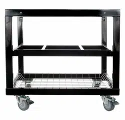
Primo Cart Assembly Instructions
www.primogrill.com
ASSEMBLY INSTRUCTIONS
HANDLE METAL PARTS WITH CARE AS SOME MAY HAVE SHARP EDGES.
1. Remove all parts from the packaging and compare to the parts list.
2. Secure 2 locking casters to one long side of the bottom frame. Use the Pan Head
Screws, Washers and Locking Nuts to attach the casters to the mounting plates. While
holding the casters flat to the bottom of the mounting plate, insert the screws from the
top and place a washer and locking nut on from the bottom and tighten. Repeat this
step for the remaining two casters and set the base frame casters down on your work
surface.
3. Install the 4 verticals. Holding the vertical with the threaded brass grommet up and
pointing to the outside of the cart frame, gently thread the hex bolt into the grommets at
the corners of the bottom frame (finger tighten only).
4. Position the shelf over the middle brackets with the threaded brass grommets facing
downward. Gently thread the hex bolts into the shelf from the bottom (finger tighten
only).
5. Install the Top Frame by orienting the brass grommets facing downward, with the
long side positioned over the locking casters on the bottom frame (the cut out side
should be above the regular swivel casters). Secure from below with the hex bolts and
finger tighten.
6. Place the cart on a flat surface and tighten all twelve hex bolts with a 10mm wrench.
DO NOT USE POWERED SCREWDRIVERS, DRILLS, OR IMPACT WRENCHES TO
TIGHTEN THE BOLTS. This could result in damage to the cart or grommets.
7. Slide the wire basket into place. You are now ready to install your Primo Grill. As an
option you may remove the top-front of the Top Frame and set the Grill. Reinstall the
part once the grill is set in place.
OPTION: AFTER ASSEMBLY
REMOVE THE TOP-FRONT OF
THE TOP FRAME AND SET THE
GRILL. REINSTALL PART ONCE
GRILL IS SET IN PLACE.
PROPER ALIGNMENT OF VERTICALS;
HOLE FOR OPTIONAL SHELF
(SOLD SEPARATELY)
GOES AT TOP FACING OUTWARD WITH
ATTACHMENT TABS FACING IN
FOR ASSEMBLING CART
TOOLS REQUIRED FOR ASSEMBLY:
ADJUSTABLE WRENCH OR 10MM AND 11MM WRENCH OR EQUIVALENT
LARGE PHILLIPS HEAD SCREWDRIVER
PART NUMBER: #368 (FOR OVAL LG 300 & XL 400), #318 (FOR JR 200)