1
FRESH IN
TM
FIN-6MD
INSTALLATION INSTRUCTIONS
Please take note that this manual uses the following symbols to emphasize particular information:
⚠ WARNING
Identifies an instruction which, if not followed, might cause serious personal
injuries including possibility of death.
CAUTION
Denotes an instruction which, if not followed, may severely damage the unit
and/or its components.
💡 Indicates a supplementary information that may relate to optional parts or
simply aim to facilitate a task.
⚠WARNING
TO REDUCE THE RISK OF FIRE, ELECTRIC SHOCK, OR INJURY TO PERSON(S) OBSERVE THE
FOLLOWING:
1. Use this unit only in the manner intended by the manufacturer. If you have questions, contact the
manufacturer.
2. Before cleaning this unit, turn off the power to the AHU at service panel. (Powered by AHU)
3. This unit is not designed to provide combustion and/or dilution air for fuel-burning appliances.
4. Installation work must be done by qualified person(s) in accordance with all applicable codes and standards,
including fire-rated construction.
5. When cutting or drilling into a wall or ceiling, do not damage electrical wiring and other hidden utilities.
6. When cleaning or performing installation of this unit, it is recommended to wear safety glasses and gloves.
7. When applicable local regulation comprises more restrictive installation and/or certification requirements,
the aforementioned requirements prevail on those of this document and the installer agrees to conform to
these at his own expense.
8. The unit must be mounted at least 3.3 feet (1.0 meter) away from any accessible opening of the duct.
9. Must be powered using a Class 2 transformer rated 10VA or higher.
CAUTION
1. Please read specification label on product for further information and requirements.
2. Do not intake air into spaces within walls or ceiling or into attics, crawl spaces, or garage. Do not attempt
to recover the exhaust air from a dryer or a range hood.
3. Intended for residential installation only in accordance with the requirements of NFPA 90B.
4. When leaving the house for a long period of time (more than two weeks), a responsible person should
regularly check if the unit operates adequately.
5. At least once a year, the unit mechanical and electronic parts should be inspected by qualified service
personnel.
6. Since the electronic control system of the unit uses a microprocessor, it may not operate correctly because
of external noise or very short power failure. If this happens, turn power off at AHU service panel and wait
approximately 10 seconds. Then, restore the power to the unit.
7. Outdoor intake hood must be weather tight and comprise a bird screen.
8. Should you decide to dispose of this unit or of parts of it, do so in accordance with local laws and regulation.
⚠ RESIDENTIAL USE ONLY ⚠
For complete warranty statement, and to register your
product online, go to www.broan-nutone.com.
READ AND SAVE THESE
INSTRUCTIONS
1. PREPARATION
Before you start:
Choose the best location and installation type for the FIN-6MD according to the current system. Ducting
widely affects the performance of this type of device. Use the shortest, straightest duct run possible to
maximize the results.
CAUTION
Do not install in an area where the temperature may exceed 160°F.
The installer shall ensure that, if necessary, an in-line heater sized according to the required airflow and outside
design heating temperature from Manual J or ASHRAE table is installed to ensure that the air delivered to the
AHU is never below the minimum temperature allowed by the manufacturer. The in-line heater shall have an
integrated airflow sensor and an over temperature sensor to prevent heating in no-flow or low-flow conditions.
When deciding if a preheater is required and whether it should be installed BEFORE or AFTER the FIN-6MD,
consider the following:
• The FIN-6MD’s minimum operating temperature is -4°F.
• The temperature distributed to the AHU should never be below the temperature recommended by the
AHU manufacturer.
• The minimum distance between the preheater and the FIN-6MD is 12 inches.
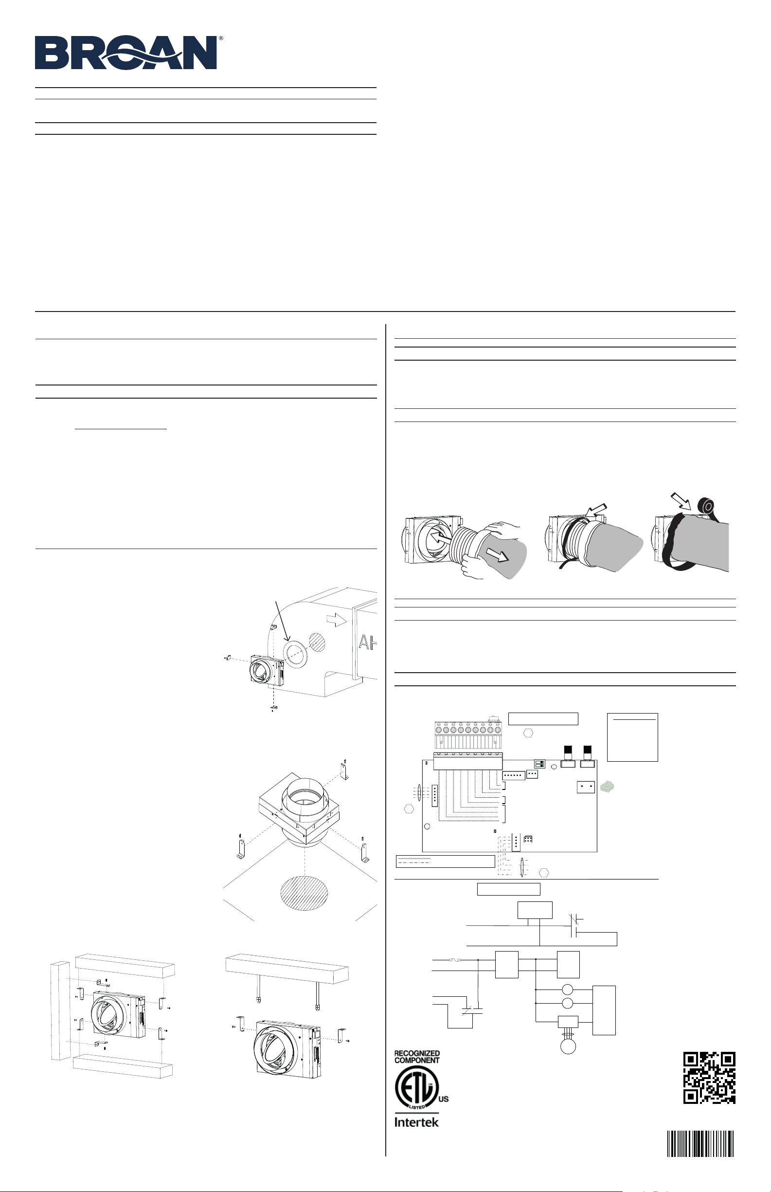
2. INSTALLATION
Always respect the orientation of the FIN-6MD and the direction of the airflow, as indicated on the
unit.
Direct-to-AHU is the fastest and easiest method:
1. Make a 6-inch diameter hole in the return duct of
your AHU.
2. Install the seal on the FIN-6MD port that will insert
the AHU ducting. Make sure that the direction of the
airflow indicated on the unit is respected.
3. Install the 3 installation brackets on the unit, as
illustrated.
4. Mark and drill holes for the brackets on the AHU
ducting and, using appropriate screws, secure the
FIN-6MD to the duct of the AHU, making sure it is
level horizontally.
💡 Use self-drilling screws (not included) to avoid
marking and drilling steps.
5. Follow steps in section 3 to connect the insulated
duct to the FIN-6MD.
6. Perform the electrical connection to the AHU following the wiring diagram in section 4.
Through a horizontal surface:
1. Make a hole in the surface that the duct will run
through. Size the hole so that the vapor barrier of the
insulated ducting is not damaged, and the insulation
not compressed.
2. Install the 3 installation brackets on the unit, as
illustrated.
3. Run a piece of insulated duct through the hole and
connect to the FIN-6MD following the steps in
section 3. Make sure the direction of the airflow as
indicated on the unit is respected.
4. Push the excess ducting on the other side of the
surface and, using appropriate screws, secure the
FIN-6MD to the surface.
5. Run the insulated duct to the AHU and connect to
the AHU ducting, making sure that the vapor barrier
sealing is leak-free.
6. Follow steps in section 3 to connect the second
insulated duct to the FIN-6MD.
7. Perform the connections to the AHU following the
wiring diagram in section 4.
Mounted under, above or beside a structure:
1. Install 2 installation brackets on the unit, as illustrated, according to the surface the unit will mount to.
2. Using appropriate screws, secure the FIN-6MD to the structure, making sure it is level horizontally. Make
sure the direction of the airflow as indicated on the unit is respected.
3. Follow steps in section 3 to connect both insulated ducts to the FIN-6MD.
4. Run the insulated duct to the AHU and connect to the AHU ducting, making sure that the vapor barrier
sealing is leak-free.
5. Perform the connections to the AHU following the wiring diagram in section 4.
UP
MOUNTED UNDER
MOUNTED ABOVE
MOUNTED BESIDE
SUSPENDED
LOGIC DIAGRAM
WIRING COLOR CODE
Reference : 1103507 rev. C
BLK BLACK
BLU BLUE
GRN GREEN
PNK PINK
RED RED
WHT WHITE
YEL YELLOW
Low voltage factory wiring
Low voltage field wiring
1
J1
1
1
J7
J9
1
J5
1
LED1
(power)
LED2
(Status)
1
J4
19
M2
RED
BLU
YEL
PNK
Damper Motor
Harness
Y
W
Gf
G
R
C
Standby Switch
SO
SI
AHU Wiring
A1
ELECTRONIC ASSEMBLY
Mode
Selection
CFM Ratio/
Damper
Selection
Power
Supply
(12V)
Low Voltage
(24VAC)
K2
R
C
G
Gf
PTC
J4-7
J4-6
J4-4
J4-5
Power
Supply
(3.3V)
MCU
K1
K2
M2
Stepper
Driver
J5-1,2,3,4
WIRING DIAGRAM
Not Used
J6
Humidity/
Temperature
Sensor
S1
GRN
RED
WHT
BLK
MCU
+24VAC Supply
Mode
Accessory
FIN-DCS
Accessory Kit
Voltage
Detection
K1
J1-2
J1-1
Accessory
24VAC
(optional)
3. CONNECTING THE INSULATED DUCTS TO THE UNIT
CAUTION
Always use insulated ducting of a minimum R-4 insulation factor.
1. Slide the inner flexible duct over the port and secure it using a tie wrap.
2. Pull the insulation over the flexible duct and port without compressing it.
3. Use duct tape to seal the outer membrane of the insulated duct to the outer ring of the port.
⚠WARNING
Make sure the outdoor intake hood is at least 18 inches above the ground and 6 feet away
from any of the following: Dryer exhaust, high-efficiency furnace vent, central vacuum vent,
gas meter exhaust, gas barbecue-grill, any exhaust from a combustion source, garbage bin
and any other source of contamination.
💡 Make sure that the outdoor intake hood is easily accessible for annual maintenance. If located above the
first floor, place it close to a window or balcony to allow easy access.
4. WIRING DIAGRAM
⚠WARNING
Risk of electric shock. Electrical wiring must be done by qualified personnel in
accordance with all applicable codes and standards. Before connecting wires, switch off
the power to the AHU at service panel and lock service disconnecting means to prevent
power from being switched on accidentally.
CAUTION
Faulty connections can cause damage to the AHU, to the thermostat and/or to this unit.
Always double check connections before turning power back on.
Scan to view our
installation video.
5011110
CONFORM TO
UL STD. 1995
💡 The terminal block can
be removed for easier
connection.
💡 Use the included tie
wrap and the loop
above the terminal
block to secure the
wires and reduce
the risk of broken
connections.
Seal
AHU wiring next page
1103500D
2
4.1 AHU WIRING
Synchronize the FIN-6MD operation with the heating and cooling run-time to prevent unnecessary central fan
operating time (refer to the dotted lines in the above diagram).
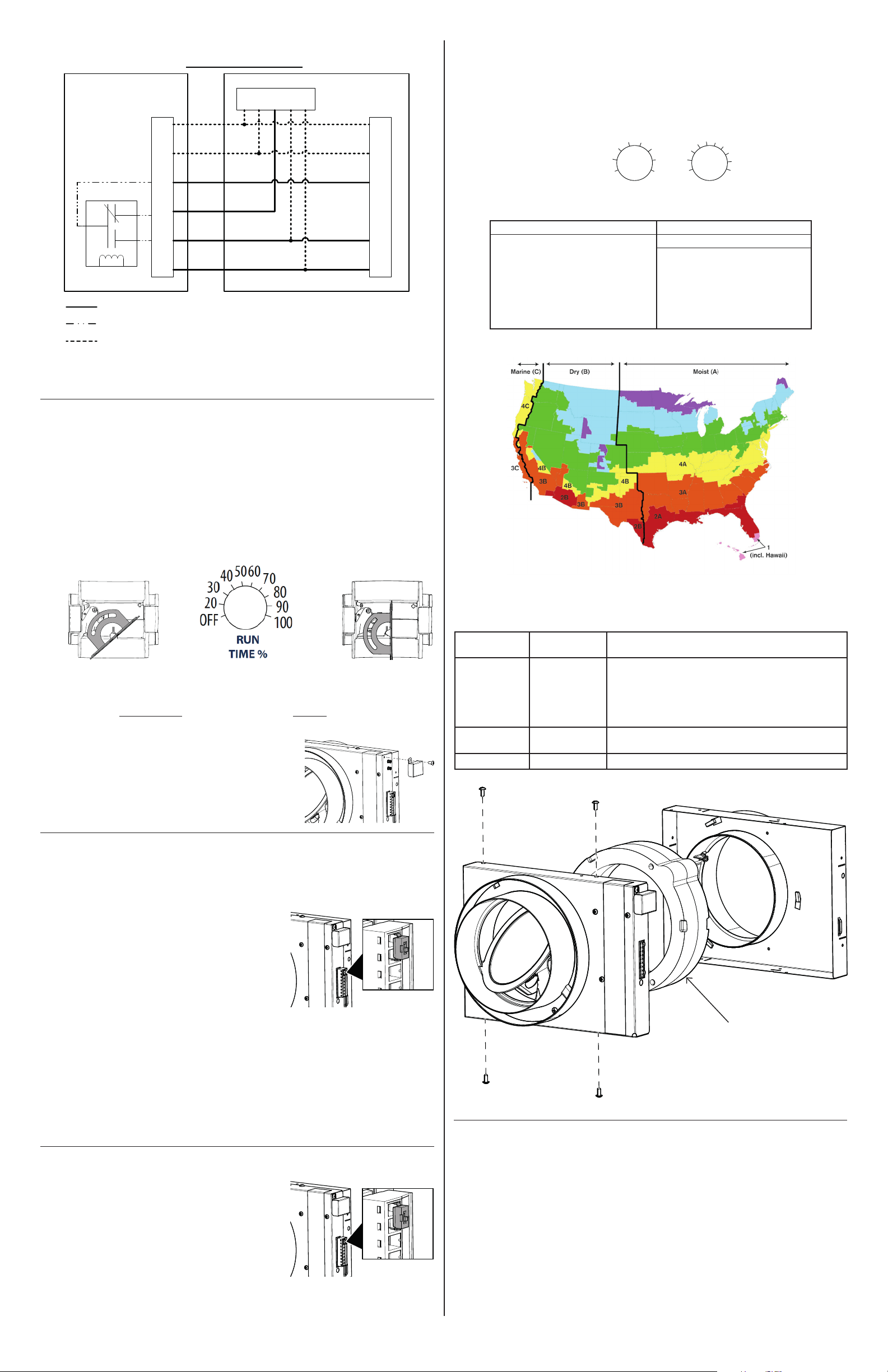
5. SETTING UP THE UNIT
When powered ON, the FIN-6MD performs a 30-second booting sequence followed by a 30-minute period
where is stays OFF, but will activate if a heating or cooling call is sent to the AHU.
Refer to local building codes to determine the required airflow.
1. Doublecheck the wiring, and turn power back ON to the AHU.
2. Set the thermostat to send a heating or cooling call, or jump R and Y on the terminal block. This will
force the ventilation ON for at least 5 minutes.
3. Measure the airflow.
If it needs adjustment, perform steps 4. If the airflow does not need adjustment, go to step 5.
4. The damper is factory set to fully open position. To adjust it, set the left pot to DAMPER
ADJUSTMENT to start the AHU blower, and wait 5 seconds. The LED will blink continuously to
indicate the unit is in DAMPER ADJUSTMENT mode.
While measuring the airflow, adjust the damper using the RUN TIME % pot until you’ve reached the
desired value.
5. Select the desired mode according to the table and map in section 7.3. Doing so also saves the
damper adjustment made in the previous step if applicable.
6. Set the RUN TIME % pot.
7. Install the supplied cover to protect the adjustment pots and
prevent an accidental change of settings. Note that the hole may
be hidden by the label.
6. TESTING
When powered ON, the FIN-6MD performs a 30-second booting sequence followed by a 30-minute period
where it stays OFF, but will activate if a heating or cooling call is sent to the AHU.
6.1 BLOWER DOOR TEST (FORCE THE DAMPER CLOSED)
If the access to the integrated switch OR to the remote switch (if
applicable) is easy, set the integrated switch OR remote switch to
OFF.
If the access to the switch is not easy, such as in an attic:
1. Turn OFF the power to the AHU at the service panel.
2. Turn the power to the AHU back ON at the service panel.
3. Wait 30 seconds for the booting sequence to execute.
4. Make sure that the thermostat will not send a heating or cooling
call.
5. Unit is OFF with its damper closed for 30 minutes, but will
activate if a heating or cooling call is sent to the AHU.
6.2 VENTILATION TEST (FORCING THE UNIT ON):
1. Turn OFF the power to the AHU at the service panel, and make sure that the integrated or remote switch
is set to ON.
2. Turn the power back ON at the service panel.
3. Wait 30 seconds for the booting sequence to execute.
4. Set the thermostat to send a heating or cooling call, or jump R and Y on the terminal block. This will force
the ventilation ON for at least 5 minutes.
7. USER INFORMATION
7.1 INTEGRATED AND REMOTE SWITCHES
This unit is equipped with an integrated ON/OFF switch. For more
convenience, your FIN-6MD can also be connected to a remote
switch.
To use a remote switch, disconnect the integrated switch and
connect the remote switch in the same manner that the integrated
one was connected.
7.2 USER SERVICING INSTRUCTIONS
• Inspect the outdoor air intake at least once a year.
• These recommendations may change according to the environmental conditions in your area.
Y
W
G
F
G
R
C
COM
NC
NO
Internal
Logic
CFIS
System
Y
W
G
R
C
Y W G R C
Thermostat
Optional Installation Wiring for Synchronization
AHU
AHU Wiring Options
J4
Mandatory Installation Wiring
CFIS Internal Hard Connections
Ref. : 1103507 rev. C
Damper
fully open
Damper
half open
Run time % =
Required Airflow
Example : Run Time % =
60 CFM
= 50%
Measured Airflow 120 CFM
ON
Integrated switch
ON
Integrated switch
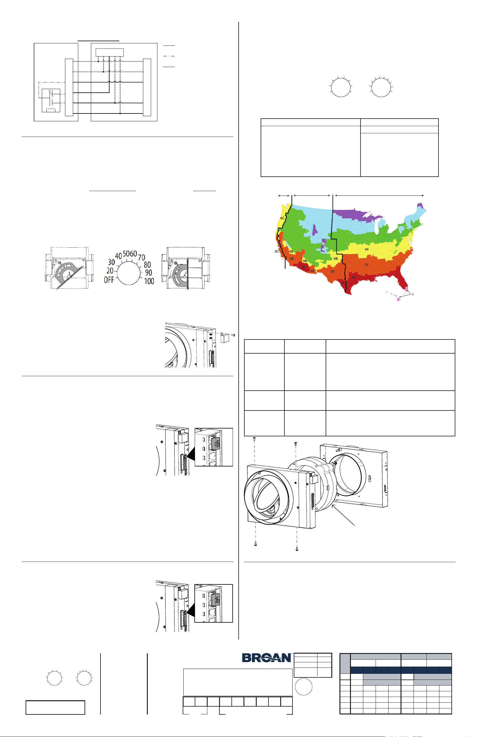
7.3 COMFORT MODE
Should the air inside your house become too humid, or if such conditions want to be prevented, the operation
mode of your FIN-6MD can be changed from a Code-Compliant one (modes 1 and 2) to a Comfort Mode
(modes A to E). Refer to the map below to make the right choice.
When making such change, make sure to only change the Mode and to leave the Run time % as it was set by
your installer. If in doubt, refer to your HVAC contractor.
7.4 TROUBLESHOOTING
A LED indicator is located to the right of the terminal block on the unit and communicates the different states
of the unit. Blinking patterns and ways to address them, if applicable, are as follows:
Sensor error 1 blink Disconnect the terminal block, and connect again. If the error
persists, replace the unit.
Damper error 2 blinks Disconnect the terminal block.
Open unit (see image below).
Perform a visual inspection and remove any debris hindering
damper movement.
Close unit and put the terminal block back in place.
If error persists, replace the unit.
Damper
adjustment mode
Continuous blink This is normal while the unit is in adjustment mode.
Learning mode 1 s ON, 10 s OFF This is normal. Will blink for 48 hours after being powered ON.
VN0012A
5B
5A
Selected mode* Climate Zones**
1 - Ashrae 2010/IRC/IMC (factory set)
Zones 1-5
2 - Ashrae 2016/2019
Zones 1-5
A - Comfort mode Hot / Humid #1
Zones 2A and 1
B - Comfort mode Hot / Humid #2
Zones 1 and 2A
C - Comfort mode Hot / Dry
Zone 2B
D - Comfort mode Mixed / Humid
Zones 3A, 4A, 5A, 3C and 4C
E - Comfort mode Mixed / Dry
Zones 3B, 4B and 5B
*Refer to the label on the unit for the full limits table.
**As defined by the Department of Energy.
OFF
20
30
40
5060
70
80
90
100
MODE RUN
TIME %
Damper
adjustment
(wait 5 sec.)
1
2
AB
C
D
E
Internal insulation
8. AVAILABLE ACCESSORIES
1. Service Parts
You can order the S1103502 replacement hardware kit, which includes the same components as the one
included with the unit.
2. Dry Contact Synchronization
Your FIN-6MD can also be synchronized with other HVAC units via a 24 VAC dry contact.
• Output mode: To activate other units operation. Requires a separate 24 VAC relay.
• Input mode: To activate your FIN-6MD operation.
Look for the FIN-DCS option kit that can be ordered separately.
NOTE: If the unit is turned off, this functionality will not work.
3
INSTRUCCIONES DE INSTALACIÓN DE
FRESH IN
TM
FIN-6MD
Considere que en este manual se usan los siguientes símbolos para enfatizar información específica:
⚠ ADVERTENCIA
Identifica una instrucción que, si no se sigue, podría provocar graves lesiones
personales, incluida la posibilidad de la muerte.
PRECAUCIÓN
Denota una instrucción que, si no se sigue, puede dañar la unidad o sus
componentes de manera grave.
💡 Indica información complementaria que se puede relacionar con piezas
opcionales o que tan solo pretenda facilitar una tarea.
⚠ SOLO USO RESIDENCIAL ⚠
Para leer la declaración de garantía completa y registrar su
producto en línea, visite www.broan-nutone.com.
LEA Y GUARDE ESTAS
INSTRUCCIONES
1. PREPARACIÓN
Antes de comenzar:
Escoja la mejor ubicación y el mejor tipo de instalación para la FIN-6MD de acuerdo con el sistema actual. Los
conductos afectan en gran medida el desempeño de este tipo de dispositivos. Use el conducto más corto y
más recto que sea posible para maximizar los resultados.
PRECAUCIÓN
No lo instale en un área en que la temperatura pueda superar los 160 °F.
El instalador garantizará, en caso de ser necesario, que se instale un calentador en línea dimensionado según
el caudal de aire necesario y la temperatura de calentamiento exterior por diseño que contemplan el Manual J o
la tabla ASHRAE, a fin de cerciorarse de que el aire suministrado a la AHU nunca sea inferior a la temperatura
mínima que permite el fabricante. El calentador en línea tendrá un sensor de caudal de aire integrado y un
sensor de exceso de temperatura, para evitar el calentamiento en condiciones de ausencia de flujo o de bajo
flujo.
Al decidir si se requiere un precalentador y si se debería instalar ANTES o DESPUÉS de la FIN-6MD,
considere lo siguiente:
• La temperatura mínima de funcionamiento de la FIN-6MD es de -4 °F.
• La temperatura distribuida hacia la AHU jamás debe ser inferior a la temperatura recomendada por el
fabricante de la AHU.
• La distancia mínima entre el precalentador y la FIN-6MD es de 12 pulgadas.
2. INSTALACIÓN
Siempre respete la orientación de la FIN-6MD y la dirección del caudal de aire, como se indica en
la unidad.
El método más rápido y más sencillo es directo a la AHU:
1. Perfore un orificio de 6 pulgadas de diámetro en el
conducto de retorno de la AHU.
2. Instale el sello en el puerto de la FIN-6MD que
insertará el conducto de la AHU. Asegúrese de
respetar la dirección del caudal de aire que se indica
en la unidad.
3. Instale los 3 soportes de instalación en la unidad,
como se aprecia en la ilustración.
4. Marque y perfore los orificios para los soportes del
conducto de la AHU y use los tornillos adecuados
para fijar la FIN-6MD al conducto de la AHU,
verificando que esté nivelado de manera horizontal.
💡 Use tornillos autoperforantes (no incluidos) para
evitar los pasos de marcado y perforación.
5. Siga los pasos de la sección 3 para conectar el conducto aislado con la FIN-6MD.
6. Realice la conexión eléctrica con la AHU de acuerdo con el diagrama de cableado de la sección 4.
Por una superficie horizontal:
1. Realice un orificio sobre la superficie que cruzará el
conducto. Dimensione el orificio de modo tal que no
se dañe la barrera de vapor del conducto aislado y
que no se comprima el aislamiento.
2. Instale los 3 soportes de instalación en la unidad,
como se aprecia en la ilustración.
3. Pase un tramo de conducto aislado por el orificio y
conéctelo con la FIN-6MD siguiendo los pasos de la
sección 3. Asegúrese de que se respete la dirección
del caudal de aire que se indica en la unidad.
4. Empuje el conducto sobrante hacia el otro lado de
la superficie y use tornillos adecuados para fijar la
FIN-6MD a la superficie.
5. Extienda el conducto aislado hasta la AHU y
conéctelo a los conductos de la AHU, verificando
que el sellado de la barrera de vapor no tenga fugas.
6. Siga los pasos de la sección 3 para conectar el
segundo conducto aislado a la FIN-6MD.
7. Realice las conexiones a la AHU de acuerdo con el
diagrama de cableado de la sección 4.
Montaje por debajo, por encima o por el lado de una estructura:
1. Instale dos soportes de instalación en la unidad, como se aprecia en la ilustración, de acuerdo con la
superficie en que se montará la unidad.
2. Use tornillos adecuados para fijar la FIN-6MD a la estructura, verificando que la nivelación horizontal.
Asegúrese de que se respete la dirección del caudal de aire que se indica en la unidad.
3. Siga los pasos de la sección 3 para conectar ambos conductos aislados a la FIN-6MD.
4. Extienda el conducto aislado hasta la AHU y conéctelo a los conductos de la AHU, verificando que el
sellado de la barrera de vapor no tenga fugas.
5. Realice las conexiones a la AHU de acuerdo con el diagrama de cableado de la sección 4.
UP
MONTAJE POR DEBAJO
MONTAJE POR ENCIMA
MONTAJE POR EL LADO
EN SUSPENSIÓN
DIAGRAMA LÓGICO
CÓDIGO DE COLORES
DE CABLEADO
Referencia : 1103507 mod. C
BLK NEGRO
BLU AZUL
GRN VERDE
PNK ROSA
RED ROJO
WHT BLANCO
YEL AMARILLO
Cableado de fábrica de baja tensión
Cableado in situ de baja tensión
1
J1
1
1
J7
J9
1
J5
1
LED1
(energía)
LED2
(estado)
1
J4
19
M2
RED
BLU
YEL
PNK
Mazo de cables
del motor del
regulador de tiro
Y
W
Gf
G
R
C
Interruptor de reserva
SO
SI
Cableado de la AHU
A1
CONJUNTO ELECTRÓNICO
Selección
de modo
Selección de
relación CFM/
regulador
de tiro
Suministro
de energía
(12V)
Baja tensión
(24 V CA)
K2
R
C
G
Gf
PTC
J4-7
J4-6
J4-4
J4-5
Suministro
de energía
(3,3 V)
MCU
K1
K2
M2
Motor de
velocidad
gradual
J5-1,2,3,4
DIAGRAMA DE CABLEADOS
No se usa
J6
Sensor de
humedad/
temperatura
S1
GRN
RED
WHT
BLK
MCU
Suministro +24 V CA
Modo
Accesorio
FIN-DCS
Kit Accesorio
Detección de
tensión
K1
J1-2
J1-1
Accesorio
24V CA
(opcional)
3. CONEXIÓN DE LOS CONDUCTOS AISLADOS A LA UNIDAD
PRECAUCIÓN
Siempre use conductos aislados con un factor de aislamiento mínimo de R-4.
1. Deslice el conducto flexible interior sobre el puerto y fíjelo con una cinta de amarre.
2. Jale el aislamiento sobre el conducto flexible y el puerto sin comprimirlo.
3. Use cinta para conductos para sellar la membrana exterior del conducto aislado en relación con el anillo
exterior del puerto.
⚠ADVERTENCIA
Asegúrese de que la campana extractora para exterior esté al menos a 18 pulgadas de
distancia del piso y a 16 pies de distancia de cualquiera de los siguientes elementos:
Escape de la secadora, ventilador de la caldera de alta eficiencia, ventilador de aspiración
central, escape del medidor de gas, asador-parrilla de gas, cualquier escape de una fuente
de combustión, bote de la basura y cualquier otra fuente de contaminación.
💡 Asegúrese de que la campana extractora para exterior sea de fácil acceso para el mantenimiento anual.
Si se encuentra más arriba del primer piso, colóquela cerca de una ventana o de un balcón, para permitir
un fácil acceso.
4. CABLEADO
⚠ADVERTENCIA
Riesgo de descarga eléctrica. El cableado eléctrico debe ser ejecutado por personal
calificado en conformidad con todos los códigos y todas las normas aplicables.
Antes de conectar cables, corte la energía desde la AHU en el panel de servicio y
bloquee los medios de desconexión del servicio para evitar que se encienda la energía
accidentalmente.
PRECAUCIÓN
Las conexiones defectuosas pueden dañar la AHU, el termostato o esta unidad. Siempre
verifique dos veces las conexiones antes de volver a conectar la energía.
Explore para ver nuestro
video de instalación.
💡 Para facilitar la
conexión, se puede
retirar el bloque de
terminales.
💡 Use la cinta de amarre
incluida y el lazo que
está sobre el bloque
de terminales para fijar
los cables y disminuir
el riesgo de conexiones
interrumpidas.
Sello
⚠ADVERTENCIA
PARA REDUCIR EL RIESGO DE INCENDIO, CHOQUE ELÉCTRICO O HERIDAS CORPORALES, SIGA
LAS INDICACIONES SIGUIENTES:
1. Utilice este aparato sólo en la forma prevista por el fabricante. Si tiene preguntas, póngase en contacto
con el fabricante.
2. Antes de limpiar el aparato, apague la alimentación del AHU en el tablero de servicio. (Alimentado por AHU)
3. Este aparato no ha sido pensado para proporcionar aire de combustión o de dilución para aparatos que
queman combustible.
4. Los trabajos de instalación han de ser realizados por personas cualificadas, de conformidad con todos los
códigos y normas aplicables, incluyendo los relativos a la construcción contra incendios.
5. Al cortar o taladrar en una pared o en el techo, procure no dañar el cableado eléctrico ni otras instalaciones ocultas.
6. Durante el mantenimiento, limpieza e instalación de este aparato se aconseja llevar lentes y guantes de
seguridad.
7. Cuando la reglamentación local aplicable sea más restrictiva en materia de instalación o certificación, dicha
reglamentación prevalecerá sobre las exigencias de este manual y el instalador acepta atenerse a dicha
reglamentación y asumir los gastos correspondientes.
8. El aparato debe montarse al menos a 3,3 pies (1 metro) de distancia de cualquier abertura accesible del conducto.
9. Debe ser alimentado usando un transformador de clase 2 clasificado 10VA o superior.
PRECAUCIÓN
1. Para mayor información sobre otras exigencias, lea la etiqueta de especificaciones que viene en el aparato.
2. No introduzca el aire en espacios situados entre paredes, en el techo o en un desván, en sótanos pequeños
ni en cocheras. No intente recuperar el aire de salida de una secadora o de una campana.
3. Diseñado para instalaciones residenciales únicamente, de conformidad con los requisitos de la norma NFPA 90B.
4. Al ausentarse de la vivienda durante un periodo largo (más de dos semanas), una persona responsable
debería verificar regularmente si el aparato funciona correctamente.
5. Al menos una vez al año, personal de servicio cualificado debería examinar las piezas mecánicas y electrónicas del aparato.
6. Dado que el sistema de control electrónico del aparato utiliza un microprocesador, es posible que no funcione
correctamente debido a los ruidos externos o a fallas de alimentación muy cortas. Si esto ocurre, apague
la alimentación del AHU en el tablero de servicio y espere aproximadamente 10 segundos. A continuación,
restablezca el suministro eléctrico al aparato.
7. La boca de admisión de aire exterior ha de ser a prueba de intemperie y llevar una tela metálica contra los pájaros.
8. Si decide deshacerse de este aparato o de partes de él, hágalo de conformidad con las leyes y reglamentos locales.
5011110
CONFORM TO
UL STD. 1995
Cableado de la AHU
en la página siguiente
1103500D
4
4.1 CABLEADO DE LA AHU
5. CONFIGURACIÓN DE LA UNIDAD
Cuando está ENCENDIDA, la FIN-6MD realiza una secuencia de arranque de 30 segundos, seguida por
un periodo de 30 minutos en el que permanece APAGADA, pero se activará si se envía una orden de
calentamiento o enfriamiento a la AHU.
Consulte los códigos locales de edificación para determinar el caudal de aire necesario.
1. Verifique dos veces el cableado y vuelva a ENCENDER la energía de la AHU.
2. Ajuste el termostato para que envíe una orden de calentamiento o enfriamiento o conecte R con Y en
el bloque de terminales. Esto forzará el ENCENDIDO de la ventilación durante al menos cinco minutos.
3. Mida el caudal de aire.
Si necesita ajuste, ejecute el paso 4. Si el caudal de aire no necesita ajuste, continúe con el paso 5.
4. El regulador de tiro viene ajustado de fábrica en posición totalmente abierto. Para ajustarlo, fije la celda
izquierda en AJUSTE DEL REGULADOR DE TIRO para arrancar el soplador de la AHU y espere
cinco segundos. El LED generará parpadeos continuos para indicar que la unidad está en modo de
AJUSTE DEL REGULADOR DE TIRO.
Mientras mida el caudal de aire, ajuste el regulador de tiro con la celda de % DE TIEMPO DE
FUNCIONAMIENTO, hasta alcanzar el valor deseado.
5. Seleccione el modo deseado de acuerdo con la tabla y el mapa de la sección 7.3. Esta acción también
guarda el ajuste del regulador de tiro del paso anterior, si corresponde.
6. Fije la celda de % de tiempo de funcionamiento.
7. Instale la cubierta suministrada para proteger las celdas de ajuste
y evitar un cambio accidental de ajustes. Recuerde que el orificio
podría quedar oculto por la etiqueta.
6. PRUEBAS
Cuando está ENCENDIDA, la FIN-6MD realiza una secuencia de arranque de 30 segundos, seguida por
un periodo de 30 minutos en el que permanece APAGADA, pero se activará si se envía una orden de
calentamiento o enfriamiento a la AHU.
6.1 PRUEBA EN LA PUERTA DEL SOPLADOR (CIERRE FORZADO DEL REGULADOR DE TIRO)
Si es fácil el acceso al interruptor integrado O al interruptor remoto
(si corresponde), fije el interruptor integrado O el interruptor remoto
en APAGADO (OFF).
Si el acceso al interruptor no es fácil, por ejemplo, en un ático:
1. Desconecte (OFF) la energía de la AHU en el panel de servicio.
2. Vuelva a ENCENDER la energía de la AHU en el panel de
servicio.
3. Espere 30 segundos para que se ejecute la secuencia de
arranque.
4. Asegúrese de que el termostato no envíe una orden de
calentamiento o enfriamiento.
5. La unidad quedará APAGADA con el regulador de tiro cerrado durante 30 minutos, pero se activará si
se envía una orden de calentamiento o enfriamiento a la AHU.
6.2 PRUEBA DE VENTILACIÓN (ENCENDIDO FORZADO DE LA UNIDAD):
1. Desconecte (OFF) la energía de la AHU en el panel de servicio y asegúrese de que el interruptor
integrado o remoto esté ENCENDIDO.
2. Vuelva a ENCENDER la energía en el panel de servicio.
3. Espere 30 segundos para que se ejecute la secuencia de arranque.
4. Ajuste el termostato para que envíe una orden de calentamiento o enfriamiento o conecte R con Y en
el bloque de terminales. Esto forzará el ENCENDIDO de la ventilación durante al menos cinco minutos.
7. INFORMACIÓN DEL USUARIO
7.1 INTERRUPTORES INTEGRADOS Y REMOTOS
Esta unidad cuenta con un interruptor integrado de ENCENDIDO/
APAGADO (ON/OFF). Para mayor comodidad, también puede
conectarse el FIN-6MD con un interruptor remoto.
Para usar un interruptor remoto, desconecte el interruptor integrado
y conecte el interruptor remoto del mismo modo en que conectó el
interruptor integrado.
7.2 INSTRUCCIONES DE MANTENIMIENTO PARA EL USUARIO
• Inspeccione la entrada de aire exterior al menos una vez al año.
• Estas recomendaciones pueden variar según las condiciones ambientales de su área.
% de
tiempo de
funcionamiento
Regulador de tiro
medio abierto
Regulador de tiro
totalmente abierto
ON
Interruptor integrado
ON
Interruptor integrado
7.3 MODO POR COMODIDAD
Si el aire al interior de su hogar se vuelve demasiado húmedo o si está intentando evitar este tipo de condiciones,
puede cambiar el modo de funcionamiento del FIN-6MD desde un modo conforme a código (modos 1 y 2) a
un modo por comodidad (modos A al E). Consulte el siguiente mapa para escoger la opción correcta.
Al aplicar dicho cambio, asegúrese de cambiar únicamente el Modo y de dejar el % de tiempo de funcionamiento
en la forma en que lo fijó el instalador. Si tiene dudas, consulte con su contratista de HVAC.
7.4 SOLUCIÓN DE PROBLEMAS
A la derecha del bloque de terminales de la unidad hay un indicador LED que comunica los distintos estados
de la unidad. Los patrones de parpadeo y las formas de abordarlos, si corresponde, son:
Error de sensor 1 parpadeo Desconecte el bloque de terminales y vuelva a conectarlo. Si el
error persiste, reemplace la unidad.
Error del
regulador de tiro
2 parpadeos Desconecte el bloque de terminales.
Abra la unidad (consulte la siguiente imagen).
Efectúe una inspección visual y retire los residuos que impidan
el movimiento del regulador de tiro.
Cierre la unidad y vuelva a colocar el bloque de terminales.
Si el error persiste, reemplace la unidad.
Modo de ajuste
del regulador
de tiro
Parpadeo continuo Es normal mientras la unidad esté en modo de ajuste.
Modo de
aprendizaje
1 segundo
ENCENDIDA,
10 segundos
APAGADA
Esto es normal. Parpadeará durante 48 horas después de ser
encendida.
VN0012A
5B
5A
Marino (C) Seco (b) Húmedo (A)
(incl. Hawái)
Modo seleccionado* Zonas climáticas**
1 Ashrae 2010/IRC/IMC (ajuste de fábrica)
Zonas 1-5
2 Ashrae 2016/2019
Zonas 1-5
A Modo de comodidad caliente / húmedo núm. 1
Zonas 2A y 1
B Modo de comodidad caliente / húmedo núm. 2
Zonas 1 y 2A
C Modo de comodidad caliente / seco
Zona 2B
D Modo de comodidad mixto / húmedo
Zonas 3A, 4A, 5A, 3C y 4C
E Modo de comodidad mixto / húmedo
Zonas 3B, 4B y 5B
*Consulte la etiqueta de la unidad para ver la tabla completa con los límites.
**Según la definición del Departamento de Energía.
APAGADO
20
30
40
50 60
70
80
90
100
MODO
% DE TIEMPO DE
FUNCIONAMIENTO
Ajuste del
regulador de tiro
(Espere 5 segundos)
1
2
AB
C
D
E
Aislamiento interno
% de tiempo de funcionamiento =
Caudal de aire requerido
Ejemplo : Run time %=
60 pi
3
/min
= 50%
Caudal de aire medido 120 pi
3
/min
APAGADO
20
30
40
50 60
70
80
90
100
MODO
% DE TIEMPO DE
FUNCIONAMIENTO
Ajuste del
regulador de tiro
(Espere 5 segundos)
1
2
AB
C
D
E
*D.P.: Punto de rocío
Modos por código:
1. ASHRAE 2010/ IRC/ IMC (ajuste de fábrica)
2. Ashrae 2016/2019
Modos por comodidad:
A. Caliente / húmedo núm. 1
B. Caliente / húmedo núm. 2
C. Caliente / seco
D. Mixto / húmedo
E. Mixto / seco
1. Fije la celda izquierda en
AJUSTE DEL REGULADOR DE
TIRO.
2. Use la celda derecha para
ajustar el regulador de tiro
desde totalmente abierta a
medio abierta.
3.
Fije el modo requerido para
guardar el ajuste del
regulador de tiro.
4. Fije el % DE TIEMPO DE
FUNCIONAMIENTO para
alcanzar el nivel de
ventilación requerido.
D.P.*
D.P.* D.P.* D.P.*
T°
T° T°
Límites inferiores (F)
Límites inferiores (F)Límites superiores (F) Límites superiores (F)
Sin orden del termostato
Orden de calentamiento
Orden de enfriamiento
Modo
seleccionado
T°
1
78
80
85
80
80
96
98
102
90
95
14
14
14
14
14
32
32
32
32
32
-4
73
75
75
75
75
88
90
95
85
86
23
23
23
23
23
40
40
40
40
40
-4
A
B
C
D
E
2
Conforme, sin límites Conforme, sin límites
-4
-4
Conforme, sin límites Conforme, sin límites
Error de sensor
1 parpadeo
2 parpadeos
Parpadeo
continuo
1 s en
ENCENDIDO y
10 s en
APAGADO
Error del regulador
de tiro
Ajuste del regulador
de tiro
Modo de aprendizaje
Broan-NuTone LLC Hartford, Wisconsin
www.broan-nutone.com 800-558-1711
Consulte las Instrucciones de instalación
para conocer más detalles.
SEÑAL
LED
Interruptor
1103497B
Cableado de la AHU
SI
SO
R
I
G
GF
W
Y
C
8. ACCESORIOS DISPONIBLES
1. Piezas de recambio
Se puede ordenar el kit de herramientas S1103502, que incluye los mismos componentes que el kit incluido
con la unidad.
2. Sincronización con contacto seco
Su FIN-6MD puede sincronizarse con otras unidades HVAC usando un contacto seco 24 V CA.
• Modo salida: Para activar el funcionamiento de otras unidades. Necesita un relé por separado de 24 V CA.
• Modo entrada: Para activar el funcionamiento de su FIN-6MD.
Busque el kit opcional FIN-DCS que puede ordenarse por separado.
NOTA: Si el aparato está apagado, esta función no funcionará.
Y
W
G
F
G
R
C
COM
NC
NO
lógica
interna
Sistema
CFIS
Y
W
G
R
C
Y W G R C
Termostato
Instalación facultativa del
cableado para sincronización
AHU
Cableado de la AHU
J4
Instalación obligatoria del
cableado
Conexiones internas del
cable CFIS
Referencia : 1103507 mod. C
Sincronizar el fucionamiento
del FIN-6MD con el tiempo de
funcionamiento del aparato AHU
para prevenir un funcionamiento
inútil del ventilador central (vease
las líneas de puntos en el
diagrama al lado).
