
Hybrid Inverter
User Manual
SUN-5K-SG03LP1-EU
SUN-6K-SG03LP1-EU
07/08/2021 11:11:10 Thu
76%
2.00
KW
-1.39
KW
0.00
KW
KW
0 7
0 5
0 5
0 5
ON
Signal
on
2.00

1. Safety Introductions
2. Product instructions
01
02-04
Contents
6. Mode
7. Fault information and processing
8. Limitation of Liability
9. Datasheet
37-39
39-42
42
43-44
10. Appendix I 45-47
11. Appendix II 48
3. Installation
4. OPERATION
5. LCD Display Icons
05-21
22
23-37
system.
for future reference.
input short circuits.
before use.
the maintenance personnel
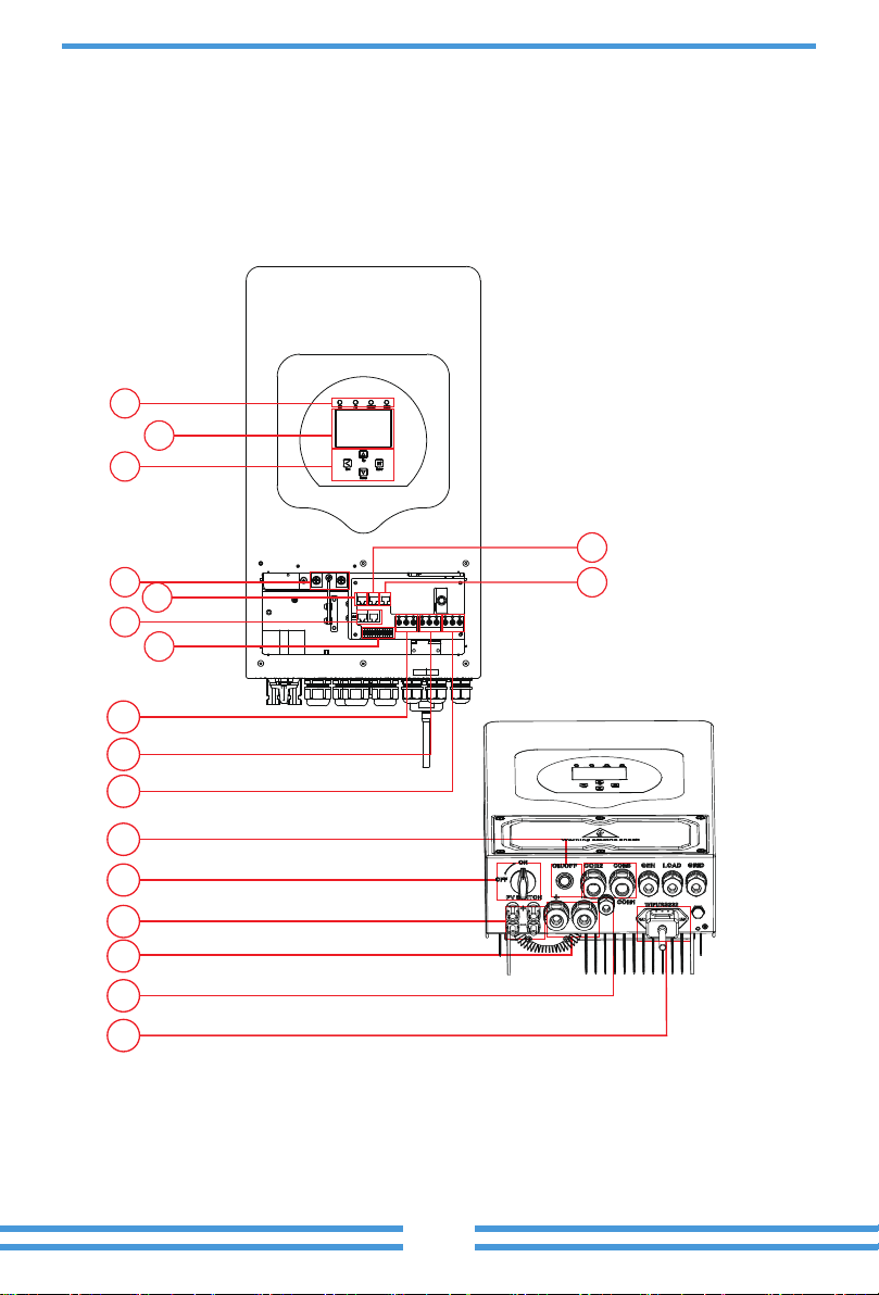
1
2
5
9
10
11
12
14
15
18
17
16
13
7
6
3
4
8
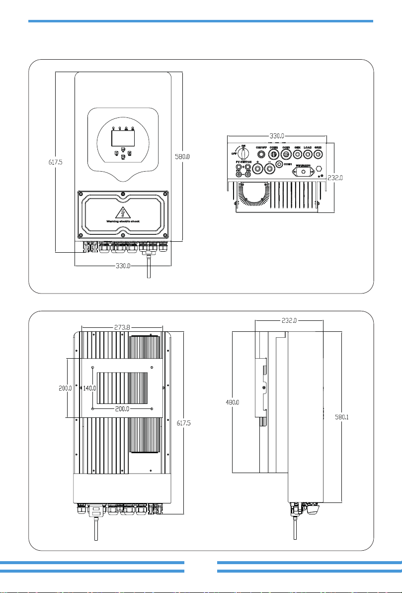
2.2 Product Size
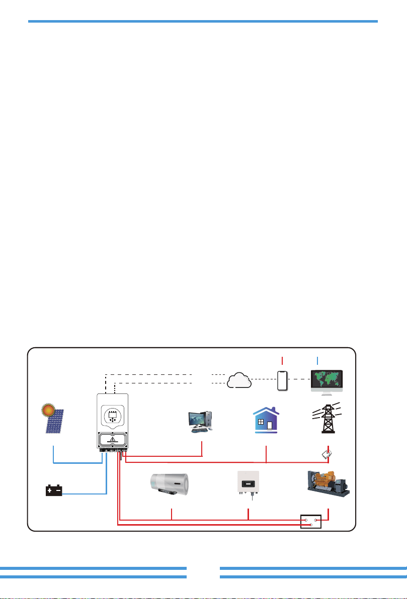
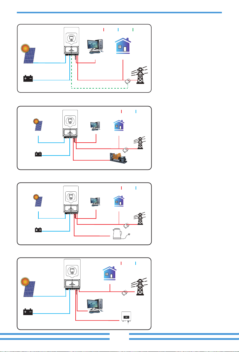
GridBackup Load
WiFI
GPRS
phoneCloud services
On-Grid Home Load
Generator
ATS
Grid-connected InverterSmart Load
Battery
Solar
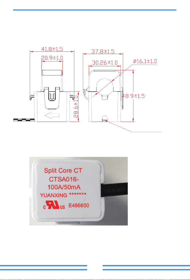
CT
AC cable DC cable
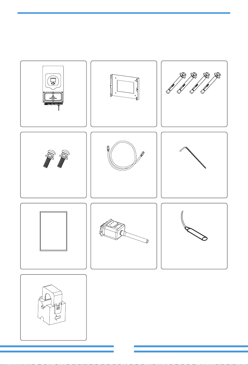
manual
Sensor Clamp
· Not in the cool air directly.
·
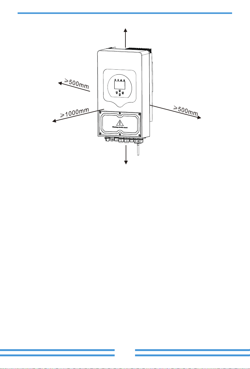
500mm
500mm
Model
Wire Size
Cable(mm )
2
Torque value(max)

connected.
recommended cables.
24mm
8.4mm
B HM G-V
G-S
T
ATS240V
input and output connectors.
Model
Wire Size
Cable(mm )
2
4
Torque value(max)
1.2Nm
6 1.2Nm
1.2Nm
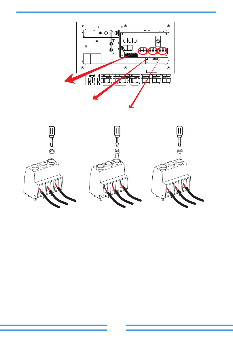
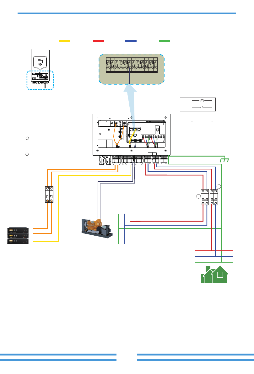
GRIDLOADGEN PORT
L
N
PE
L
N
PE
L
N
PE
GRID
LOAD
GEN PORT
Model
Wire Size
Cable(mm )
2
4
unit.

Inverter Model 5kW 6kW3.6kW
2
Load
L N PEL N PE
L N PE
Grid
Gen
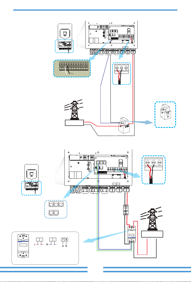
*Note
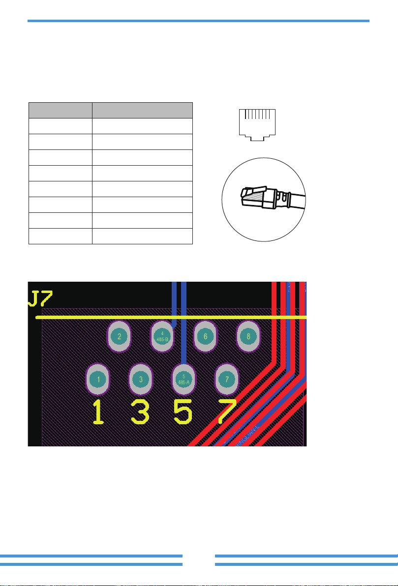
21 43
Output
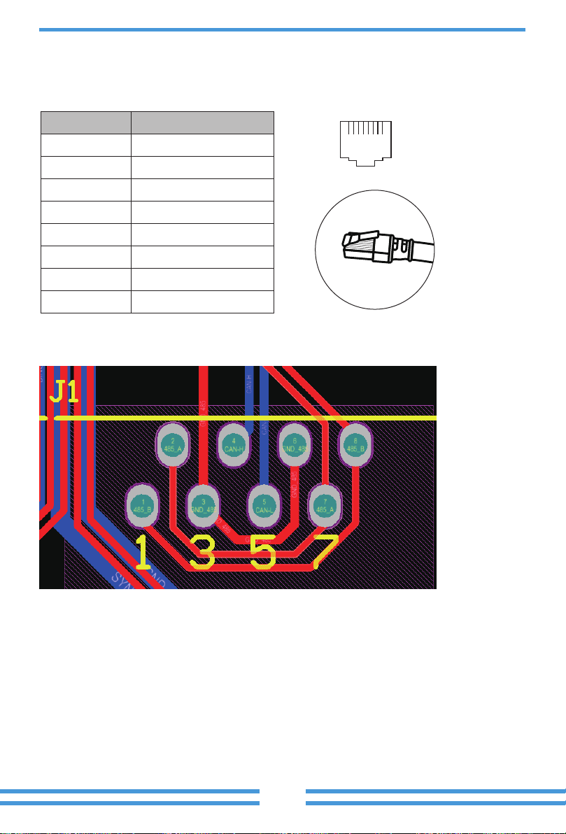
RS 485
Grid input
RS485B
RS485A
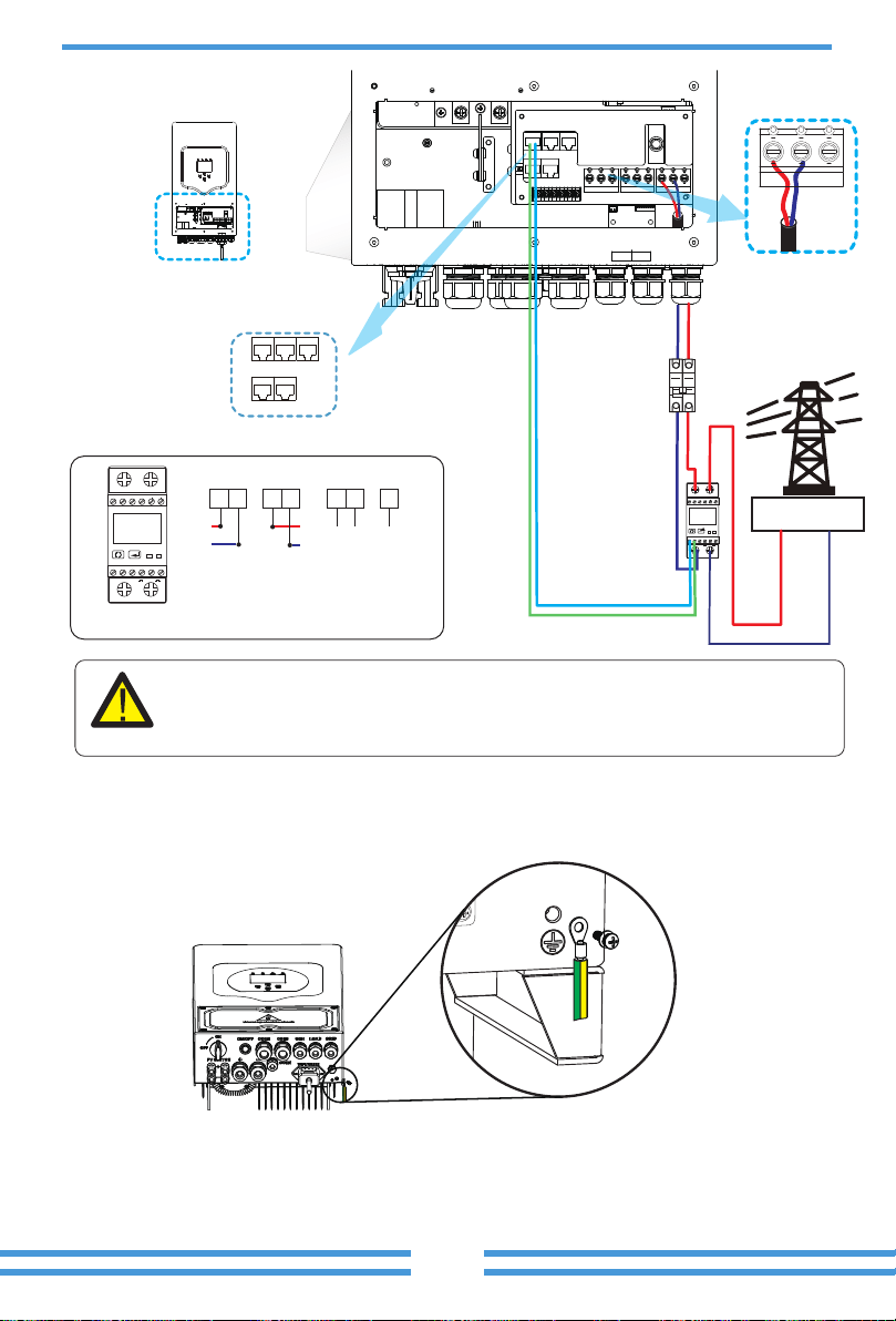
RS485B
Note:
1
2
3
B
4
GND
Output
RS 485 GND
Input
1
2
3
B
4
GND
5
3
6
7
A B
N
N
1
2 4
RS485B
RS485A
E-BAR
E-BAR
AC Breaker
AC Breaker AC Breaker
Load
L L
N
PE
N
PE
Battery
Diesel
generator
Diesel
generator
BMS
Load
L N PE
Grid
L L
N
PE
N
PE
Grid
CT
CT
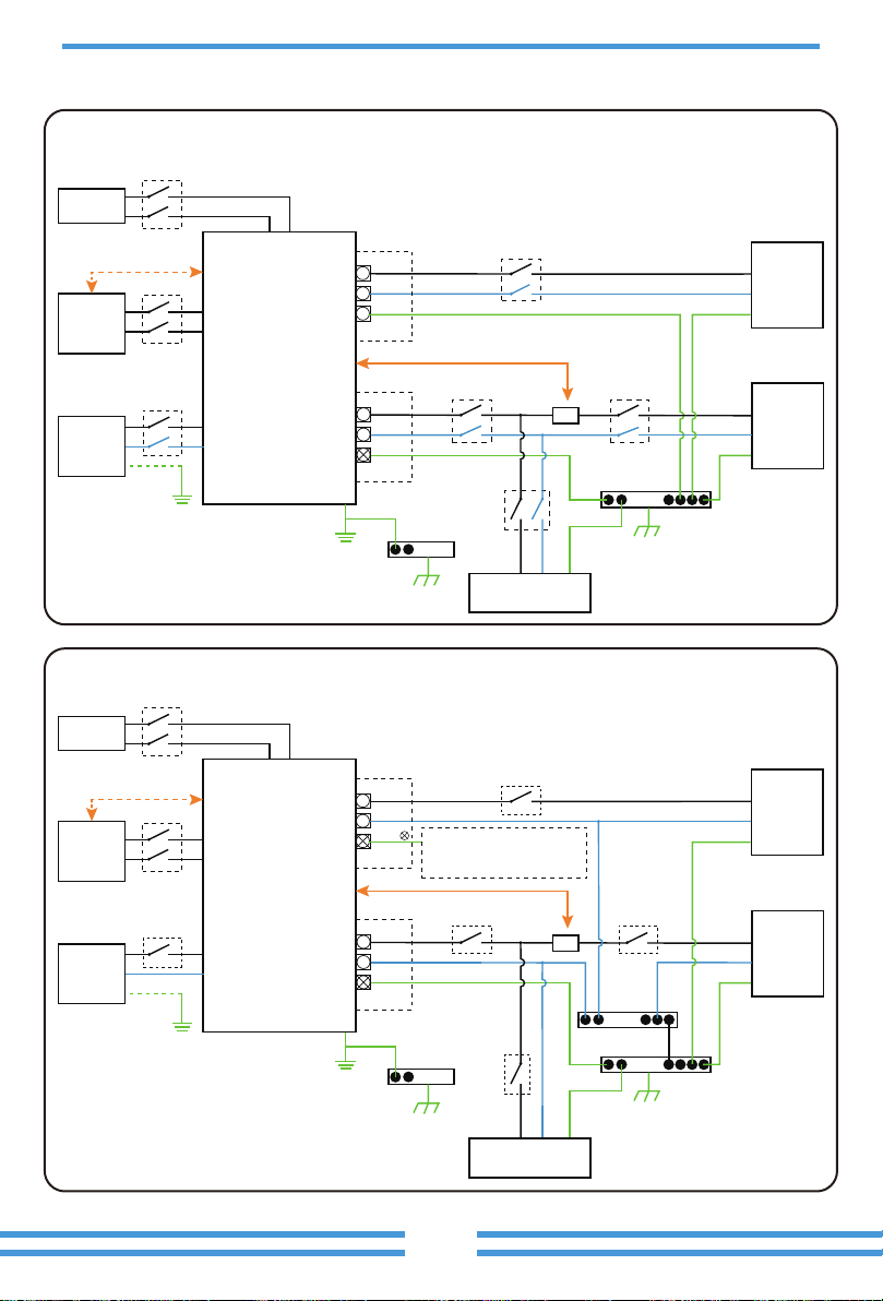
Home Loads
Hybrid Inverter
AC Breaker
DC Breaker
PV
DC Breaker
E-BAR
E-BAR
N-BAR
AC Breaker
AC Breaker AC Breaker
Load
L L
N
PE or
N
PE
Battery
PV
BMS
Load
L N PE
Grid
L L
N
PE
N
PE
Grid
CT
CT
Home Loads
Hybrid Inverter
AC Breaker
DC Breaker
DC Breaker
Do not connect this terminal
when the neutral wire and PE
wire are connected together.
E-N
Link
Load
L N PEL N PE
L N PE
Grid
Gen
B HM G-V
G-S
T
ATS240V
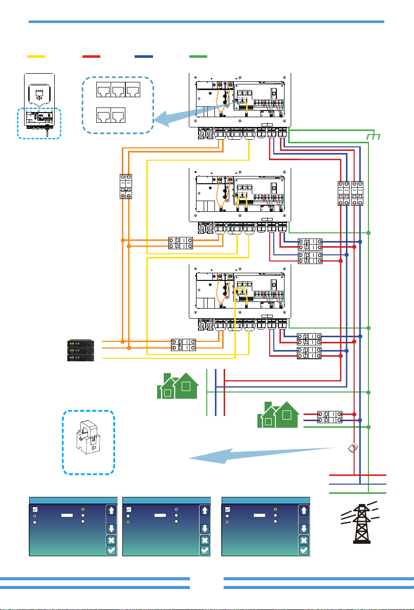
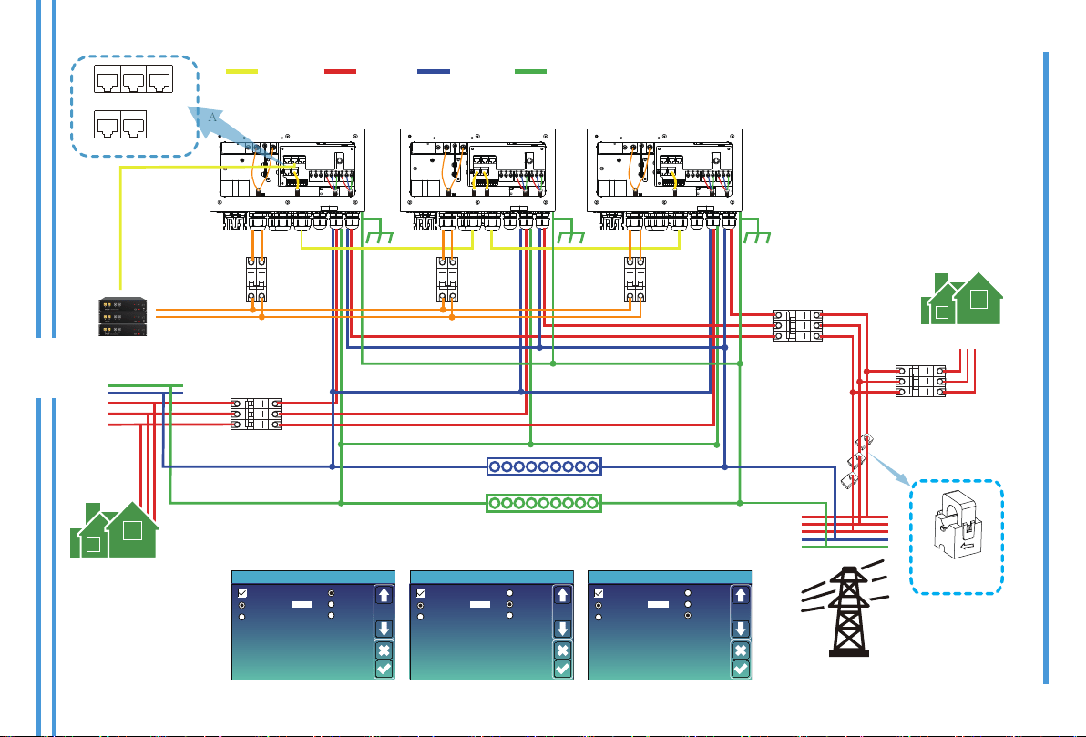
Parallel
Master
Slave
Modbus SN
01
A Phase
B Phase
C Phase
Advanced Function
Paral.
Set3
Parallel
Master
Slave
Modbus SN
02
A Phase
B Phase
C Phase
Advanced Function
Paral.
Set3
Parallel
Master
Slave
Modbus SN
03
A Phase
B Phase
C Phase
Advanced Function
Paral.
Set3
Load
L N PEL N PE
L N PE
Grid
Gen
Load
L N PEL N PE
L N PE
Grid
Gen
Load
L N PEL N PE
L N PE
Grid
Gen
Parallel
Master
Slave
Modbus SN
01
A Phase
B Phase
C Phase
Advanced Function
Paral.
Set3
Parallel
Master
Slave
Modbus SN
02
A Phase
B Phase
C Phase
Advanced Function
Paral.
Set3
Parallel
Master
Slave
Modbus SN
03
A Phase
B Phase
C Phase
Advanced Function
Paral.
Set3
4. OPERATION
LED Indicator
DC
Normal
Messages
Funcon Key
Descripon
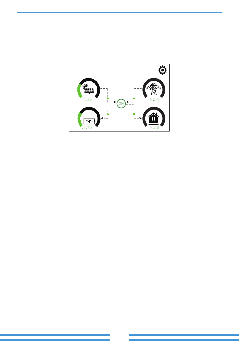
25%
12/18/2020 09:21:00 Fri
1.85
KW
-1.79
KW
0.04
KW
0.02
KW
0 7
0 5
0 5
0 5
ON

Power: 0W
Stand-by
0.0Hz
Energy
CT: 0W
0V 0.0A
BUY
Today=0.0KWH
Total =8.60 KWH
Today=2.2KWH
Total =11.60 KWH
SELL
LD: 0W
Grid
①
②
③
Power: 0W Today=0.0 KWH
Total =0.40 KWHL: 0V
Load
Energy
①
②
③
sensors
Power: 44W DC-T:52.6C
AC-T:41.0CL1: 240V
l1:0.6A
Inverter
③
①
②
Power: 2923W Grid Tie Power: 2923W
Energy
Today=0.3 KWH
Total =3.90 KWH
PV1-V: 0V
PV1-I: 0A
P1: 0W
PV2-V: 0V
PV2-I: 0.1A
P2: 0W
PV3-V: 0V
PV3-I: 0.0A
P3: 0W
Solar
③
④
① ②
Stand-by
SOC: 36%
U:50.50V
I:-58.02A
Power: -2930W
Temp:30.0C
Batt
Li-BMS
Mean Voltage:50.34V Charging Voltage :53.2V
Total Current:55.00A Discharging Voltage :47.0V
Mean Temp :23.5C Charging current :50A
Total SOC :38% Discharging current :25A
Sum
Data
Details
Data
Dump Energy:57Ah
Li-BMS
Volt
1
2
3
50.38V 19.70A 30.6C 52.0% 26.0Ah 0.0V 0.0A 0|0|0
50.33V 19.10A 31.0C 51.0% 25.5Ah 53.2V 25.0A 0|0|0
50.30V 16.90A 30.2C 12.0% 6.0Ah 53.2V 25.0A 0|0|0
4
5
0.00V 0.00A 0.0C 0.0% 0.0Ah 0.0V 0.0A 0|0|0
0.00V 0.00A 0.0C 0.0% 0.0Ah 0.0V 0.0A 0|0|0
0.00V 0.00A 0.0C 0.0% 0.0Ah 0.0V 0.0A 0|0|0
0.00V 0.00A 0.0C 0.0% 0.0Ah 0.0V 0.0A 0|0|0
0.00V 0.00A 0.0C 0.0% 0.0Ah 0.0V 0.0A 0|0|0
0.00V 0.00A 0.0C 0.0% 0.0Ah 0.0V 0.0A 0|0|0
0.00V 0.00A 0.0C 0.0% 0.0Ah 0.0V 0.0A 0|0|0
0.00V 0.00A 0.0C 0.0% 0.0Ah 0.0V 0.0A 0|0|0
0.00V 0.00A 0.0C 0.0% 0.0Ah 0.0V 0.0A 0|0|0
0.00V 0.00A 0.0C 0.0% 0.0Ah 0.0V 0.0A 0|0|0
0.00V 0.00A 0.0C 0.0% 0.0Ah 0.0V 0.0A 0|0|0
0.00V 0.00A 0.0C 0.0% 0.0Ah 0.0V 0.0A 0|0|0
6
7
8
9
10
11
12
13
14
15
Curr
Volt Curr
Temp SOC Energy
Charge
Fault
Sum
Data
Details
Data
Li-BMS
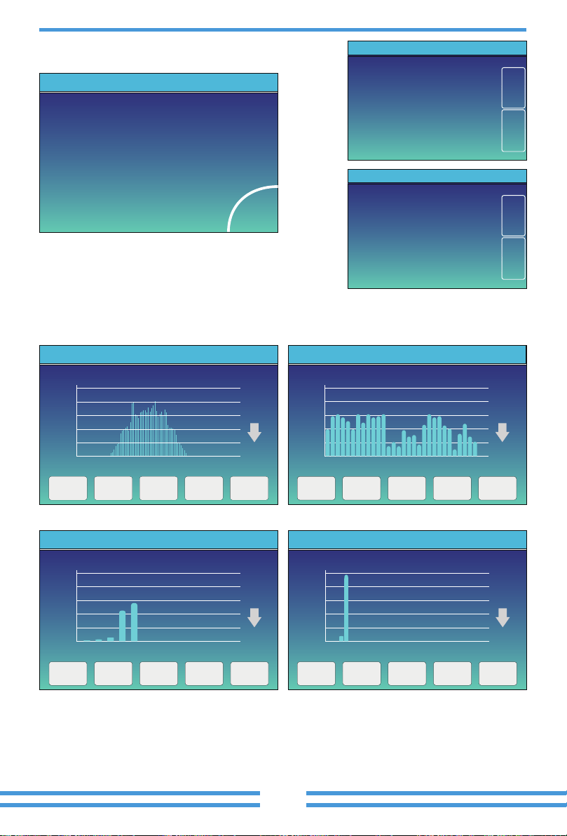
2019-5-28
20%
1 3 5 7 9 11 13 15 17 19 21 23
40%
60%
80%
100%
3000W
Solar Power Production:Day
5-2019
400
0
05 10 15 20 25 30
800
1200
1600
2000
2000Wh
System Solar Power:Month
CANCEL Day Month Year Total
2019
40
1 2 3 4 5 6 7 8 9 10 11 12
80
120
160
200
KWh
System Solar Power:Year
CANCEL Day Month Year Total
TOTAL
400
0
20 20 20 20 20 20 20 20 20 20 20 20 20 20 20 20 20
16 18 20 22 24 26 28 30 32 34 36 38 40 42 44 46 48
800
1200
1600
2000
2000KWh
CANCEL Day Month Year Total
System Grid Power:Total
CANCEL Day Month Year Total
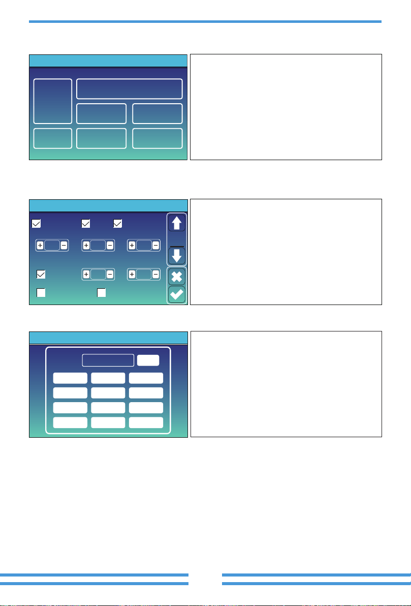
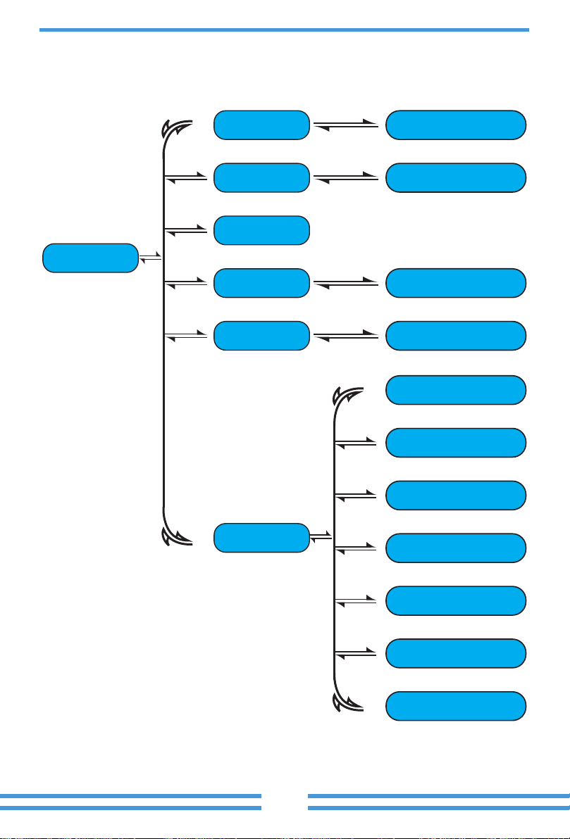
System Work Mode
Battery
Setting
Grid Setting
Gen Port
Use
Basic
Setting
System Setup
Device Info.
Advanced
Function
Basic
Set
Time Syncs Beep Auto Dim
24-Hour
Basic Setting
Year Month Day
Hour Minute
Lock out all changesFactory Reset
2019 03
09 15
17
out is 7777.
PassWord
DELX--X--X--X
1 2 3
4 5 6
7 8 9
CANCEL 0 OK
07/08/2021 11:11:10 Thu
76%
2.00
KW
-1.39
KW
0.00
KW
KW
0 7
0 5
0 5
0 5
ON
Signal
on
2.00
Batt Mode
Lithium
Use Batt V
Battery Setting
Activate Battery
Low Power Mode<Low Batt
Disable Float Charge
Max A Charge
Batt Capacity
Max A Discharge
40A
40A
400Ah
Batt
Mode
Use Batt %
No Batt
system.
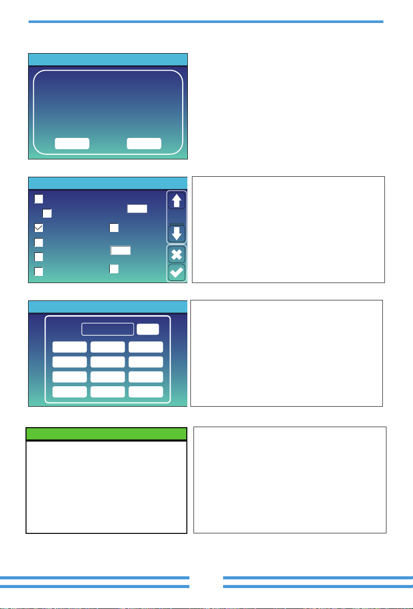
Grid ChargeGen Charge
Grid SignalGen Signal
Gen Force
Low Noise Mode
Battery Setting
Start
A
30% 30%
40A
40A
Batt
Set2
①
②
③
No use
Disable.
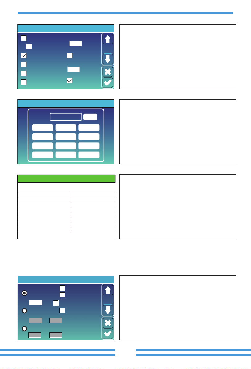
Float V 53.6V 20%
35%
50%
-5
Absorption V
57.6V
Equalization V
57.6V
Equalization Days
Shutdown
Low Batt
Restart
TEMPCO(mV/C/Cell)
Batt Resistance
30 days
Equalization Hours
3.0
25mOhms
Battery Setting
Set3
Batt
①
②
③
Baery Type
Absorpon Stage
Float Stage
Torque value
(every 30 days 3hr )
Gel
Lithium Mode
Shutdown
Low Batt
Restart
40%
20%
10%
00
Battery Setting
Set3
Batt
the document.
resume.
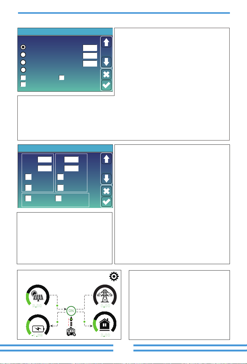
Power: 1392W
L1: 228V
Freq:50.0Hz
Today=0.0 KWH
Total =2.20 KWH
Generator
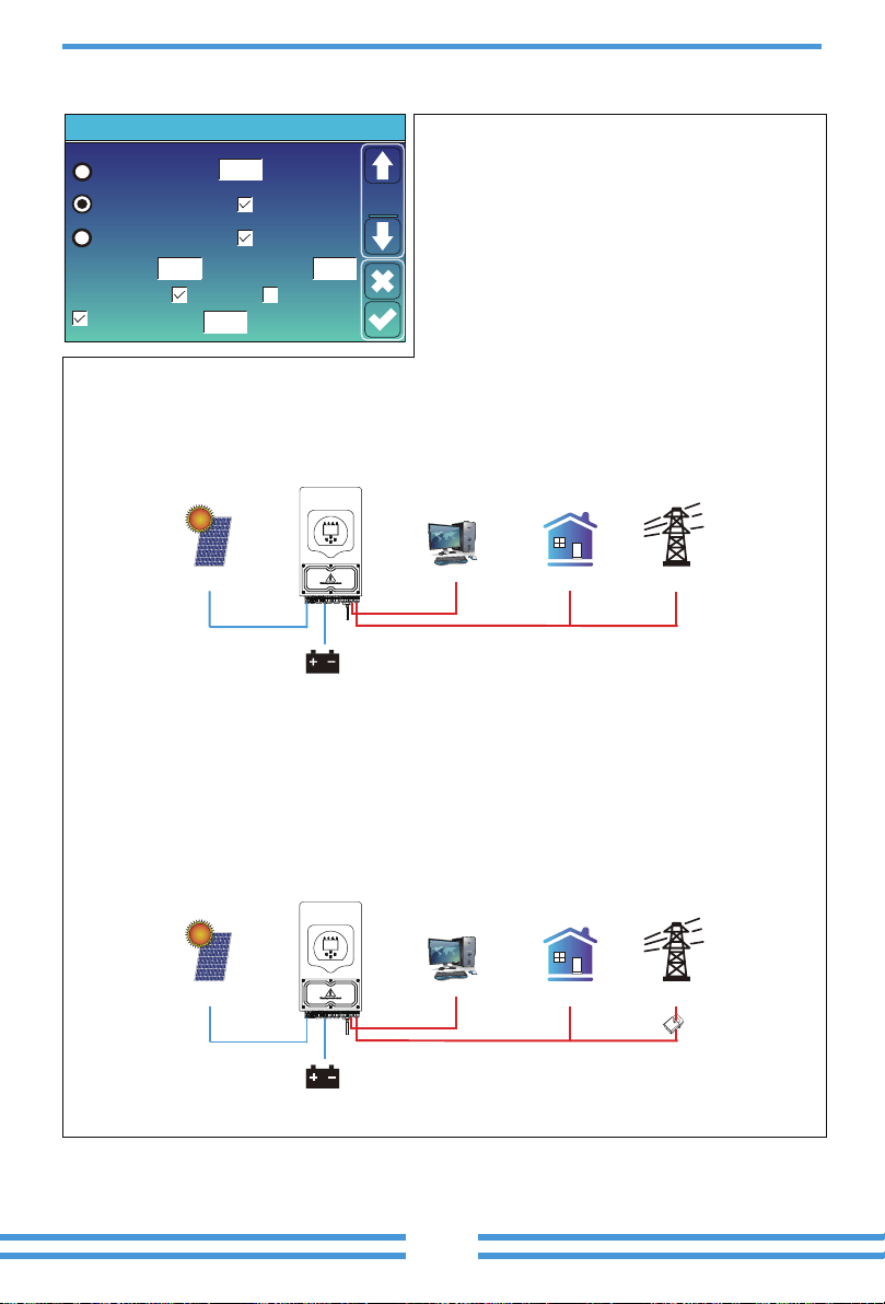
Zero Export To Load
Max Solar Power
Zero Export To CT
Max Sell Power
Energy pattern
BattFirst LoadFirst
System Work Mode
Solar Sell
Solar Sell
5000
5000
Power
5000
Zero-export Power
20
Selling First
Work
Mode1
Grid Peak Shaving
2. Grid.
load.
GridBackup Load On-Grid Home Load
Battery
Solar
CT
GridBackup Load On-Grid Home Load
Battery
Solar
period.
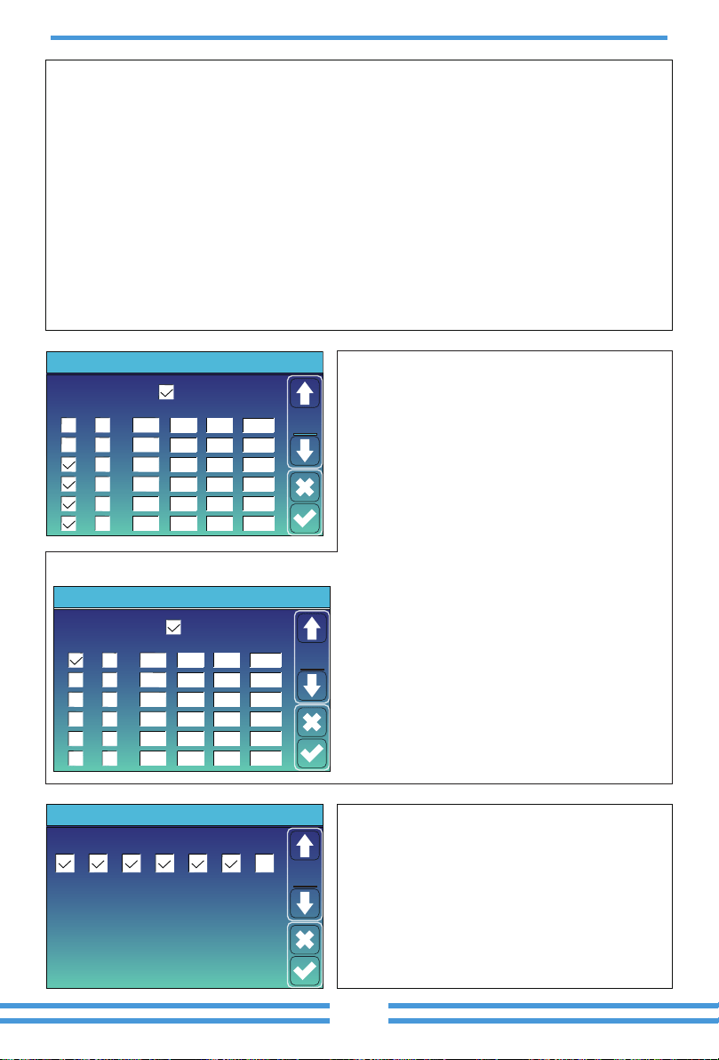
Time Of Use
Time
System Work Mode
Batt
Grid
Charge
Gen
01:00
05:00
09:00
13:00
17:00
21:00
5:00
9:00
13:00
17:00
21:00
01:00
Power
5000
5000
5000
5000
5000
5000
49.0V
50.2V
50.9V
51.4V
47.1V
49.0V
Work
Mode2
Time Of Use
Time
System Work Mode
Batt
Grid
Charge
Gen
01:00
05:00
08:00
10:00
15:00
18:00
5:00
8:00
10:00
15:00
18:00
01:00
Power
5000
5000
5000
5000
5000
5000
80%
40%
40%
80%
40%
35%
Work
Mode2
Mon
System Work Mode
Tue Wed Thu Fri Sat Sun
Work
Mode4
FW
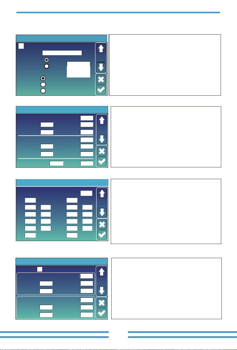
Grid Setting/F(W)
F(W)
Start freq f
Over frequency
50.20Hz
Start delay f
0.00s
Stop freq f 50.20Hz
Droop f
40
%PE/Hz
Stop delay f
0.00s
Start freq f
Under frequency
49.80Hz
Start delay f
Stop freq f 49.80Hz
Droop f 40%PE/Hz
Stop delay f
0.00s
0.00s
Grid
Set4
Reconnection Time PF
60s
Grid Setting/Connect
Low frequency
Normal connect
48.00Hz
Low voltage
185.0V
High frequency 51.50Hz
Normal Ramp rate 60s
Reconnect Ramp rate 60s
High voltage
265.0V
Low frequency
Reconnect after trip
Low voltage
High frequency
51.30Hz
High voltage
263.0V
48.20Hz
187.0V
Grid
Set2
PF
Over voltage U>(10 min. running mean)
Grid Setting/IP Protection
260.0V
Set3
Grid
--
HV1
265.0V
0.10s
--
HV2
265.0V
0.10s
HV3
--
LV1
185.0V
0.10s
--
LV2
185.0V
0.10s
185.0V
LV3
--
HF1
51.50Hz
0.10s
--
HF2
0.10s
HF3
--
LF1
48.00Hz
0.10s
--
LF2
0.10s
LF3
0
HV3
HF3
265.0V
51.50Hz
51.50Hz
48.00Hz
48.00Hz
1.000
General Standard
NRS097G99
0/16
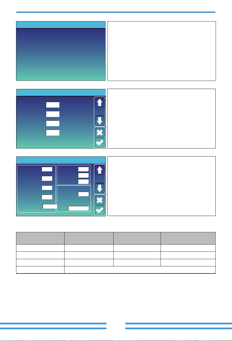
Grid Setting
Grid Mode
Grid
Set1
Grid Frequency
50HZ
60HZ
General Standard
INV Output Voltage
220V
240V
230V
200V
Grid Type
120/240V Split Phase
120/208V 3 Phase
Single Phase
Unlock Grid Setting
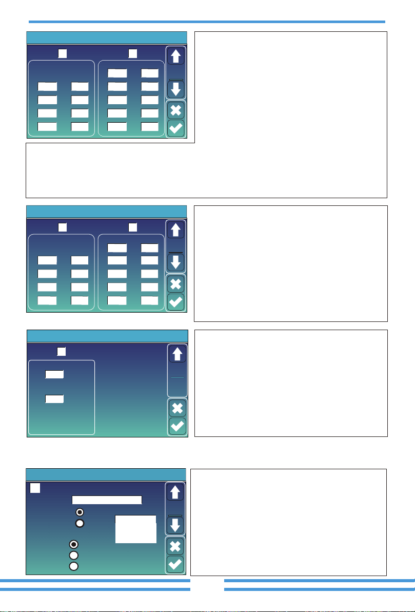
Grid Setting/V(W) V(Q)
V(W)
V(Q)
V1
109.0%
P2
V2
110.0%
P3
P4
V3
111.0%
V4
111.0%
P1
100%
20%
20%
20%
Lock-in/Pn Lock-out/Pn
V1
90.0%
Q2
V2
95.7%
Q3
Q4
V3
104.3%
V4
112.2%
Q1
44%
0%
0%
-60%
Grid
Set5
Grid Setting/P(Q) P(F)
P(Q)
P(PF)
P1
0%
Q2
P2
0%
Q3
Q4
P3
0%
P4
0%
Q1
0%
0%
0%
0%
P1
0%
PF2P2
0%
PF3
PF4
P3
0%
P4
0%
PF1
-2.400
0.000
0.000
6.000
Grid
Set6
Lock-in/Pn Lock-out/Pn
Grid Setting/LVRT
L/HVR
HV1
115%
LV1
50%
Grid
Set7
recommended.
5%
20%
50%
50%
mode.
4/16
Grid Setting
Grid Mode
Grid
Set1
Grid Frequency
50HZ
60HZ
CEI 0-21
INV Output Voltage
220V
240V
230V
200V
Grid Type
120/240V Split Phase
120/208V 3 Phase
Single Phase
Unlock Grid Setting
Grid Warning
Grid Mode: CEI 0-21
Grid Type: 50Hz
220V Single Phase
CANCEL OK
PassWord
DELX--X--X--X
1 2 3
4 5 6
7 8 9
CANCEL 0 OK
Solar Arc Fault ON
Clear Arc_Fault
System selfcheck
BMS_Err_Stop
0ms
20001
Backup Delay
Advanced Function
Func
Set1
DRM
Gen peak-shaving
CEI 0-21 Report
CT Ratio
Signal ISLAND MODE
Secondly, �ck “System selfchek” ,
then it will ask you input the password,
and the default password is 1234.
Inverter ID : 2012041234
Self-Test OK 8/8
Testing 59.S1... Test 59.S1 OK!
Testing 59.S2... Test 59.S2 OK!
Testing 27.S1... Test 27.S1 OK!
Testing 27.S2... Test 27.S2 OK!
Testing 81>S1... Test 81>S1 OK!
Testing 81>S2... Test 81>S2 OK!
Testing 81<S1... Test 81<S1 OK!
Testing 81<S2... Test 81<S2 OK!
successfully.
PassWord
DELX--X--X--X
1 2 3
4 5 6
7 8 9
CANCEL 0 OK
Solar Arc Fault ON
Clear Arc_Fault
System selfcheck
BMS_Err_Stop
0ms
20001
Backup Delay
Advanced Function
Func
Set1
DRM
Gen peak-shaving
CEI 0-21 Report
CT Ratio
Signal ISLAND MODE
Inverter ID : 2012041234
Self-Test Report
59.S1 threshold253V 900ms 59.S1: 228V 902ms
59.S2 threshold264.5V 200ms 59.S2: 229V 204ms
27.S1 threshold195.5V 1500ms 27.S1: 228V 1508ms
27.S2 threshold 34.5V 200ms 27.S2: 227V 205ms
81>.S1 threshold 50.2Hz 100ms 81>.S1: 49.9Hz 103ms
81>.S2 threshold 51.5Hz 100ms 81>.S2: 49.9Hz 107ms
81<.S1 threshold 49.8Hz 100ms 81<.S1: 50.0Hz 95ms
81<.S2 threshold 47.5Hz 100ms 81<.S2: 50.1Hz 97ms
Set1
Mode
OFFON
Generator Input
SmartLoad Output
Micro Inv Input
On Grid always on
GEN PORT USE
52.00Hz
100%
95%
Power
Rated Power
AC Couple Fre High
500W
8000W
PORT
Set1
GEN connect to Grid input
AC couple on grid side
AC couple on load side
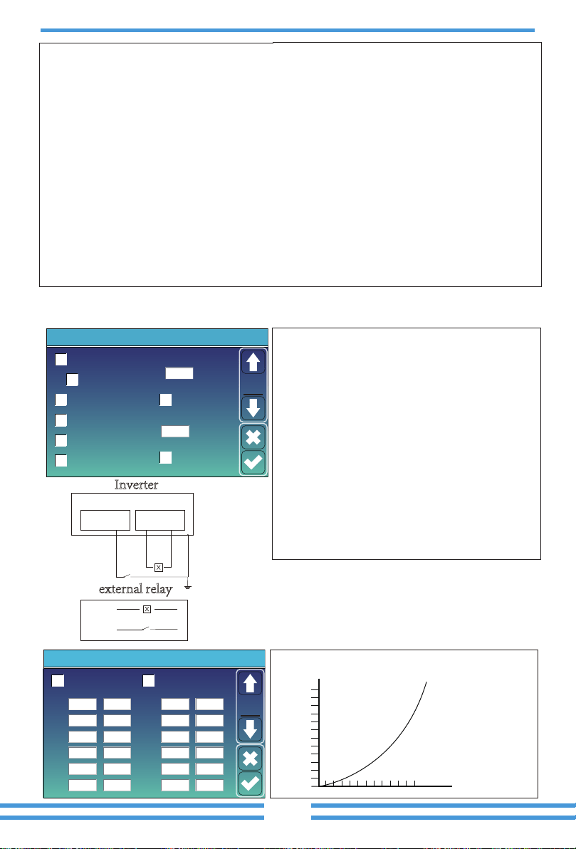
Disable. this is only for factory.
or bond.
Note
Note
Solar Arc Fault ON
Clear Arc_Fault
System selfcheck
BMS_Err_Stop
0ms
20001
Backup Delay
Advanced Function
Func
Set1
DRM
Gen peak-shaving
CEI 0-21 Report
CT Ratio
Signal ISLAND MODE
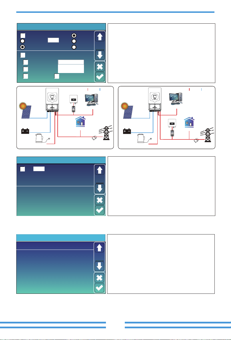
DC 1 for WindTurbine
V1
V2
V3
V4
V5
V6
V7
V8
V9
V10
V11
V12
90V
110V
130V
150V
170V
190V
0.0A
1.5A
3.0A
4.5A
6.0A
7.5A
210V
230V
250V
270V
290V
310V
9.0A
10.5A
12.0A
13.5A
15.0A
16.5A
DC 2 for WindTurbine
Advanced Function
Wind
Set2
Volt
1
2
3
50.38V 19.70A 30.6C 52.0% 26.0Ah 0.0V 0.0A 0|0|0
50.33V 19.10A 31.0C 51.0% 25.5Ah 53.2V 25.0A 0|0|0
50.30V 16.90A 30.2C 12.0% 6.0Ah 53.2V 25.0A 0|0|0
4
5
0.00V 0.00A 0.0C 0.0% 0.0Ah 0.0V 0.0A 0|0|0
0.00V 0.00A 0.0C 0.0% 0.0Ah 0.0V 0.0A 0|0|0
0.00V 0.00A 0.0C 0.0% 0.0Ah 0.0V 0.0A 0|0|0
0.00V 0.00A 0.0C 0.0% 0.0Ah 0.0V 0.0A 0|0|0
0.00V 0.00A 0.0C 0.0% 0.0Ah 0.0V 0.0A 0|0|0
0.00V 0.00A 0.0C 0.0% 0.0Ah 0.0V 0.0A 0|0|0
0.00V 0.00A 0.0C 0.0% 0.0Ah 0.0V 0.0A 0|0|0
0.00V 0.00A 0.0C 0.0% 0.0Ah 0.0V 0.0A 0|0|0
0.00V 0.00A 0.0C 0.0% 0.0Ah 0.0V 0.0A 0|0|0
0.00V 0.00A 0.0C 0.0% 0.0Ah 0.0V 0.0A 0|0|0
0.00V 0.00A 0.0C 0.0% 0.0Ah 0.0V 0.0A 0|0|0
0.00V 0.00A 0.0C 0.0% 0.0Ah 0.0V 0.0A 0|0|0
6
7
8
9
10
11
12
13
14
15
Curr
Volt Curr
Temp SOC Energy
Charge
Fault
Sum
Data
Details
Data
Li-BMS
Volt
1
2
3
50.38V 19.70A 30.6C 52.0% 26.0Ah 0.0V 0.0A 0|0|0
50.33V 19.10A 31.0C 51.0% 25.5Ah 53.2V 25.0A 0|0|0
50.30V 16.90A 30.2C 12.0% 6.0Ah 53.2V 25.0A 0|0|0
4
5
0.00V 0.00A 0.0C 0.0% 0.0Ah 0.0V 0.0A 0|0|0
0.00V 0.00A 0.0C 0.0% 0.0Ah 0.0V 0.0A 0|0|0
0.00V 0.00A 0.0C 0.0% 0.0Ah 0.0V 0.0A 0|0|0
0.00V 0.00A 0.0C 0.0% 0.0Ah 0.0V 0.0A 0|0|0
0.00V 0.00A 0.0C 0.0% 0.0Ah 0.0V 0.0A 0|0|0
0.00V 0.00A 0.0C 0.0% 0.0Ah 0.0V 0.0A 0|0|0
0.00V 0.00A 0.0C 0.0% 0.0Ah 0.0V 0.0A 0|0|0
0.00V 0.00A 0.0C 0.0% 0.0Ah 0.0V 0.0A 0|0|0
0.00V 0.00A 0.0C 0.0% 0.0Ah 0.0V 0.0A 0|0|0
0.00V 0.00A 0.0C 0.0% 0.0Ah 0.0V 0.0A 0|0|0
0.00V 0.00A 0.0C 0.0% 0.0Ah 0.0V 0.0A 0|0|0
0.00V 0.00A 0.0C 0.0% 0.0Ah 0.0V 0.0A 0|0|0
6
7
8
9
10
11
12
13
14
15
Curr
Volt Curr
Temp SOC Energy
Charge
Fault
Sum
Data
Details
Data
Li-BMSDevice Info.
Inverter ID: 1601012001 Flash
MAIN:Ver 0-5213-0717
HMI: Ver0302
Alarms Code
F64 Heatsink_HighTemp_Fault
F64 Heatsink_HighTemp_Fault
F64 Heatsink_HighTemp_Fault
2019-03-11 15:56
2019-03-08 10:46
2019-03-08 10:45
Occurred
Device
Info
ATS
ON
Advanced Function
Func
Set4
Parallel
Master
Slave
Ex_Meter For CT Meter Select
C Phase Grid Side INV Meter2
00
CHNT-3P
Modbus SN
Advanced Function
Paral.
Set3
A Phase 0/4
B Phase
B Phase
A Phase
C Phase
CHNT-1P
Eastron-3P
Eastron-1P
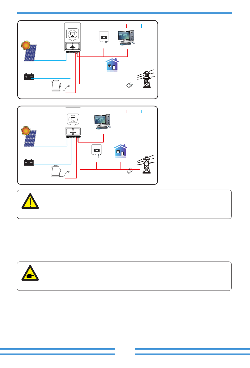
CT
Battery
Solar
Grid
Grid
Backup Load
On-Grid Home Load
Smart Load
AC cable
DC cableAC cable DC cable
CT
Battery
Solar
Backup Load
On-Grid Home Load
Smart Load
On-Grid Inverter
Meter
On-Grid Inverter
Meter
Grid
Backup Load On-Grid Home Load
Battery
Solar
CT
AC cable DC cable
Smart Load
AC cable
DC cable
CT
Battery
Solar
Grid
Backup Load
On-Grid Home Load
On-Grid Inverter
Grid
Backup Load On-Grid Home Load
CT
Battery
Solar
AC cable DC cable
COM cable
Grid
Backup Load On-Grid Home Load
Battery
Solar
CT
AC cable DC cable
Generator
can operate reliably.
is as detailed as possible.
AC cable
DC cable
CT
Battery
Solar
Grid
Backup Load
On-Grid Home Load
On-Grid Inverter
Smart Load
AC cable
DC cable
CT
Battery
Solar
Grid
Backup Load
On-Grid Home Load
On-Grid Inverter
Smart Load

Error code Descripon Soluons

Error code Descripon Soluons

product.
Model
Baery Input Date
PV String Input Data
yes
2
AC Output Data
Grid Type
Efficiency
Protecon
3600
3960
SUN-3.6K-
SG03LP1-EU
SUN-5K-
SG03LP1-EU
6000
6600
SUN-6K-
SG03LP1-EU

Model
Cerficaons and Standards
General Data
SUN-3.6K-
SG03LP1-EU
SUN-5K-
SG03LP1-EU
SUN-6K-
SG03LP1-EU
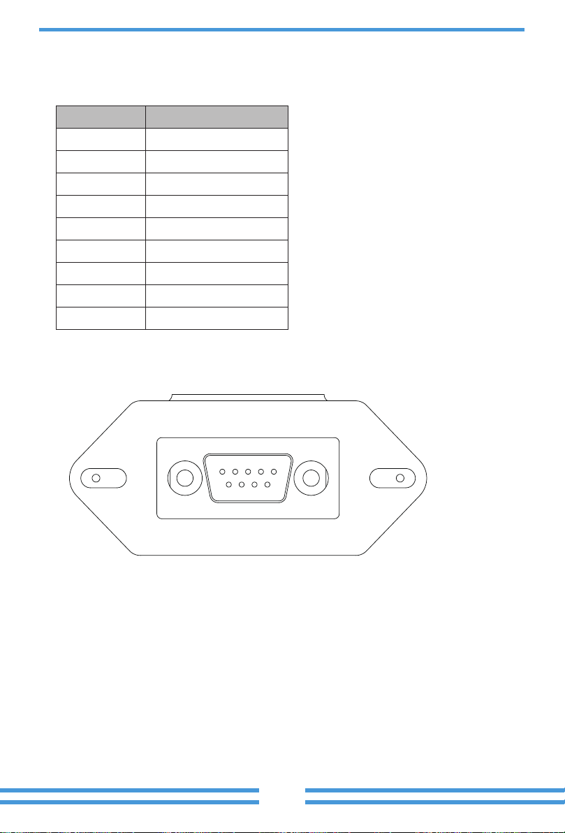
RS232