Loading ...
Loading ...
Loading ...
22
Pay attention to the followings to run through the cables under the unit using conduit tube. (The guard
plater is required to remove before performing piping and wiring works.)
1
1
.
.
Do not lead the power supply wiring and transmission wiring through the same conduit. Moreover, keep a
distance of at least 1-31/32(50mm) between the power supply wiring and transmission wiring
2
2
.
.
Cut cross line at rubber bush and securely attach it to the knock-out hole for cable protection.
3
3
.
.
Attach the guard plate to avoid entrance of rats or other small animals into the unit.
4
4
.
.
Avoid the wirings from touching the refrigerant pipes, plate edges and electrical parts inside the unit.
Completely seal the end of conduit tube with sealing materials to avoid the ingress of rain into the conduit.
Make a drain hole at the lowest part of the conduit tube.
CAUTION
(1)Connect power supply wiring to each outdoor unit. Connect an ELB, fuse and main switch () to each outdoor
unit.
(2)Connect power supply wiring to each indoor unit to be connected to the same outdoor unit. Connect an ELB,
fuse and main switch() to each indoor unit group.
(
(
3
3
)
)
Connect the transmission wiring between indoor units and outdoor units, as shown in figure.
Connect the transmission wiring in the same refrigerant cycle. (In case that the refrigerant pipe of indoor unit
is connected to the outdoor unit, connect the transmission wiring to the same indoor unit.) Connecting the
refrigerant pipe and transmission wiring to the systems of different refrigerant cycle may lead to malfunction.
(
(
5
5
)
)
Use 2-core lead wires such as shielded twist pair cable for the transmission wiring. (Do not use 3-core or
over.)
(
(
7
)
)
The transmission wiring is required to be separated from the power supply wiring. Keep a distance of at least
1-31/32in.(50mm) between the transmission wiring and the power supply wiring, and also a distance of min.
49.2ft.(5m) between the transmission wiring and power supply wiring of other electrical device. If the above is
not secured, put the power supply wiring into the metal conduit to separate from other wirings.
Connect the following transmission wiring to Terminal 1 and 2 of TB2 in the outdoor unit A (main unit).
For the combination modules, DSW settings of Main and Sub are required.
Alarm occurs if the transmission wires between outdoor units are connected to Terminal 1 and 2 for H-
NET.
In case that alarm is indicated on the LCD of Main outdoor unit, follow the "7-segment" display when the
ain outdoor unit checking.
Perform function setting from Main outdoor unit.
When indoor units are connected to the SW BOX, refer to technical handbook for wiring.
Tightly secure the power source wiring by using the cord clamp inside the unit.
.4 Electrical Wiring Connection of The System
(9)Do not connect the power supply wiring to terminal board for transmission wiring (TB2). Printed circuit
board may be damaged.
(10) Connect the earth wire for outdoor/indoor units. The earth wiring work under the condition of 100 Ω
(max.) ground resistance should be performed by a qualified person.
NOTES:
● between outdoor unit and indoor unit
● between outdoor unit and indoor unit in other refregerants cycles
CAUTION
4
4
.
.
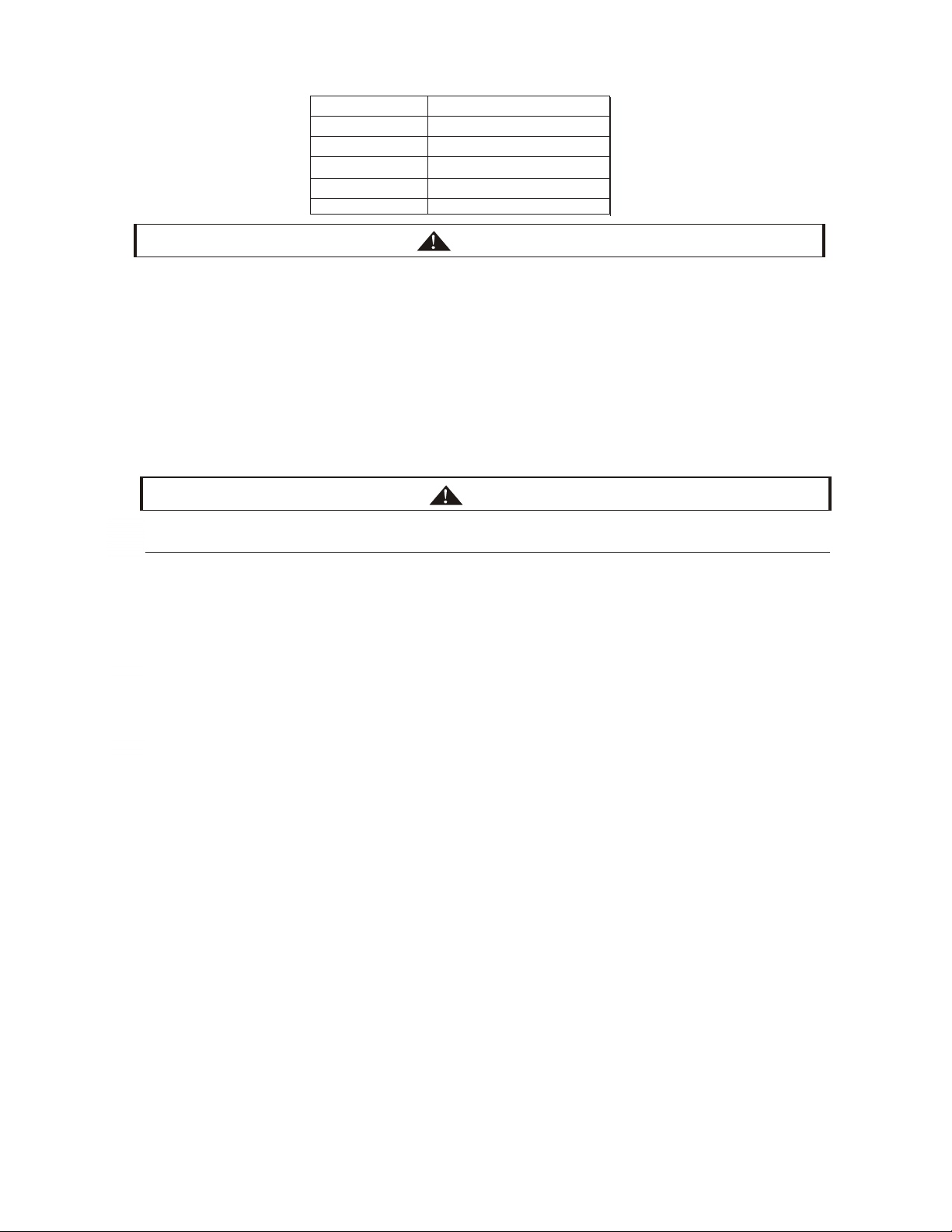
Screw
S
ize Tightening Torque
M4
M5
1.5~
1.8 ft·lbs(2.0~2.4N·m)
M6
M8
M10
3.0~3.7 ft·lbs(
4.0~5.0N·m)
6.6~8.1 ft·lbs(9.0~11.0N·m)
13.3~17 ft·lbs(18.0~23.0N·m)
0.7~1.0 ft·lbs(1.0~1.3N·m)
<Tighten screws for the terminal board according to the following table.>
1.
2.
3.
4.
5.
(3)
(4)
(5)
(7)
(8)
1.
2.
3.
4.
TS
6 UH-T
Loading ...
Loading ...
Loading ...