PAC9060
PAC12060
PAC18060
PAC24060
INSTALLATION MANUAL
Identification of parts
Installation instructions
Safety Precautions
3
Preparation before use
2
Indoor unit
4
Outdoor unit
4
Display introduction
5
Select the installation locations
10
Indoor unit installation
11
Outdoor unit installation
16
Installation diagram
9
Air purging
16
Maintenance
6
Protection
7
Troubleshooting
8
Contents
Safety introduction
1
Remote controller operating instructions.See"remote controller
instructions".
4
1
Safety instructions
To guarantee the unit work normally, please read the manual carefully before installation,
and try to install strictly according to this manual.
Do not let air enter the refrigeration system or discharge refrigerant when moving the
air conditioner.
After installing, the consumer must operate the air conditioner correctly according
to this manual, keep a suitable storage for maintenance and moving of the air
conditioner in the future.
There must be an air-break switch.
Check the connecting cables and pipes carefully, make sure they are correct and firm
before connecting the power of the air conditioner.
Type of fuse used on indoor unit controller is Ø5mm X 20mm,with rating T 3.15A 250VAC.
Properly ground the air conditioner into the earth.
Warning: Risk of electric shock can cause injury or death: Disconnect all remote
electric power supplies before servicing .
The installation instructions for appliances that are intended to be permanently
connected to fixed wiring, and have a leakage current that may exceed 10 mA,
shall state that the installation of a residual current device (RCD) having a rated
residual operating current not exceeding 30 mA is advisable.
The maximum length of the connecting pipe between the indoor unit and outdoor
unit should be less than 5 meters. It will affect the efficiency of the air conditioner
if the distance longer than that length.
This appliance can be used by children aged from 8 years and above and persons
with reduced physical, sensory or mental capabilities or lack of experience and
knowledge if they have been given supervision or instruction concerning use of the
appliance in a safe way and understand the hazards involved. Children shall not
play with the appliance. Cleaning and user maintenance shall not be made by
children without supervision.
If the supply cord is damaged, it must be replaced by the manufacturer, its service
agent or similarly qualified persons in order to avoid a hazard.
The batteries in remote controller must be recycled or disposed of properly.
Disposal of Scrap Batteries --- Please discard the batteries as sorted municipal
waste at the accessible collection point.
If the appliance is fixed wiring, the appliance must be fitted with means for
disconnection from the supply mains having a contact separation in all poles that
provide full disconnection under over voltage category III conditions, and these
means must be incorporated in the fixed wiring in accordance with the wiring rules.
The appliance shall not be installed in the laundry.
The appliance shall be installed in accordance with national wiring regulations.
The air conditioner must be installed by professional or qualified persons.
2
Preparation before use
Before using the air conditioner, be sure to check and preset as the following.
Remote Controller presetting
Auto Restart Presetting
Hold down any button of the remote controller for about 2 seconds, the back-light will be turned on.
It will be turned off automatically after about 10 seconds.
Back-light function (optional)
Each time after the remote control is replaced with new batteries or is energized, remote control auto
presetting heat pump.If the air conditioner you purchased is a Cooling Only one, heat pump remote
controller can also be used .
The air conditioner has Auto-Restart function.
You can set or cancel this function when the air conditioner is running.
Hold down the emergency button(ON/OFF) for a few seconds, this function will be set if you hear
beep twice. If you just hear beep once, this function will be canceled.
Safeguarding the environment
Note
When charging refrigerant into the system, make sure to charge in liquid state, if
the refrigerant of the appliance is R22 or R410A.Otherwise, chemical composition
of refrigerant (R22 or R410A) inside the system may change and thus affect
performance of the air conditioner.
According to the character of
pressure of the tube is very high, so be sure to be careful when you install and
repair the appliance.
refrigerant (R410A,the value of GWP is 2088), the
If the supply cord is damaged, it must be replaced by the manufacturer, its
service agent or similarly qualified persons in order to avoid a hazard.
The air conditioner must be installed by a professional engineer.
The temperature of refrigerant circuit will be high, please keep the
interconnection cable away from the copper tube.
This appliance is made of recyclable or re-usable material. Scrapping must be carried out in
compliance with local waste disposal regulations. Before scrapping it, make sure to cut off the mains
cord so that the appliance cannot be re-used.
For more detailed information on handling and recycling this product, contact your local authorities
who deal with the separate collection of rubbish or the shop where you bought the appliance.
SCRAPPING OF APPLIANCE
This appliance is marked according to the European Directive 2012/19/EC, Waste Electrical and
Electronic Equipment (WEEE).
This marking indicates that this product should not be disposed
with other household wastes throughout the EU. To prevent possible
harm to the environment or human health from uncontrolled waste
disposal,recycle it responsibly to promote the sustainable reuse of
material resources. To return your used device, please use the return
and collection systems or contact the retailer where the product was
purchased. They can take this product for environmental safe recycling.
Preset
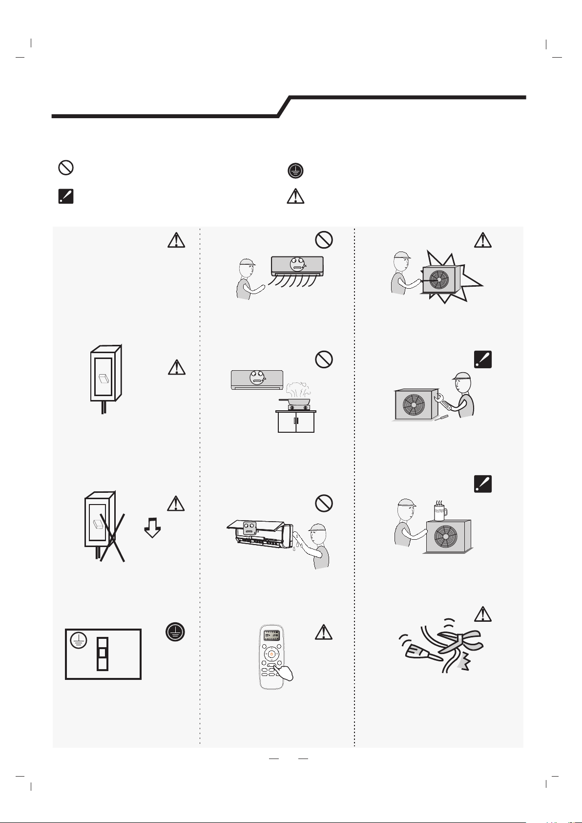
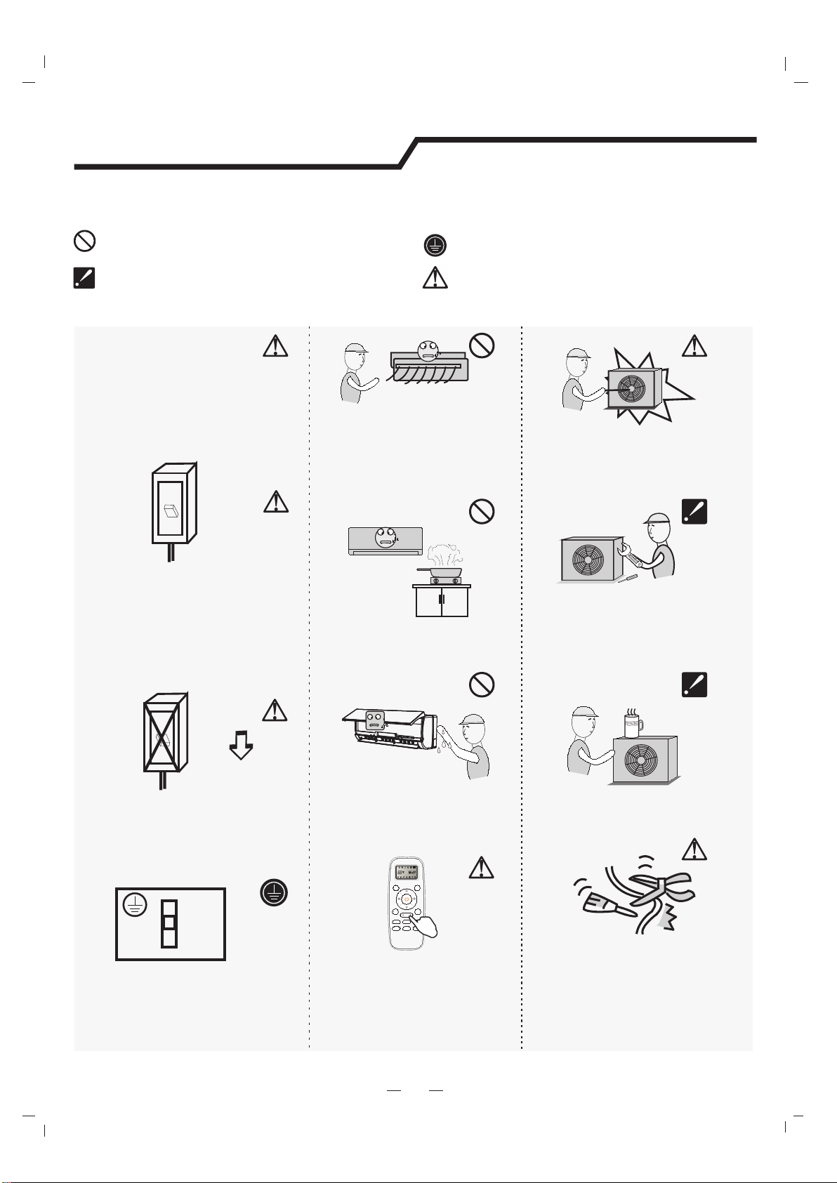
Safety precautions
Symbols in this Use and Care Manual are interpreted as shown below.
Be sure not to do.
Pay attention to such a situation.
Grounding is essential.
Warning: Incorrect handling could
cause a serious hazard, such as death,
serious injury, etc.
3
Do not use the power supply
circuit breaker or pull off the plug
to turn it off during operation.
This may cause a fire due to
spark, etc.
Keep the power supply circuit
breaker or plug from dirt.
Connect the power supply cord
to it firmly and correctly, lest an
electric shock or a fire break out
due to insufficient contact.
Use correct power supply in
accordance with the rating plate
requirement. Otherwise, serious
faults or hazard may occur or a
fire maybe break out.
Do not knit, pull or press the power
supply cord, lest the power supply cord
be broken. An electric shock or fire is
probably caused by a broken power
supply cord.
Never insert a stick or similar obstacle
to the unit. Since the fan rotates at high
speed, this may cause an injury.
Do not repair the appliance by yourself.
If this is done incorrectly, it may cause
an electric shock, etc.
Turn off the appliance by remote
control firstly before cutting off
power supply if malfunction occurs.
It is harmful to your health if the cool
air reaches you for a long time. It is
advisable to let the air flow be
deflected to all the room.
Prevent the air flow from reaching
the gas burners and stove.
Do not touch the operation buttons
when your hands are wet.
Do not put any objects on the outdoor
unit.
It is the user's responsibility to
make the appliance be grounded
according to local codes or
ordinances by a licenced
technician.
OFF
OFF
ON
ON
ON
OFF
MODE
SMART
QUIET
DIMMER
ECONOM Y
FEEL
FAN SPEED
CLOCK
TIMER ON
TIMER OFF
SLEEP
TEMP.
TEMP.
SUPER

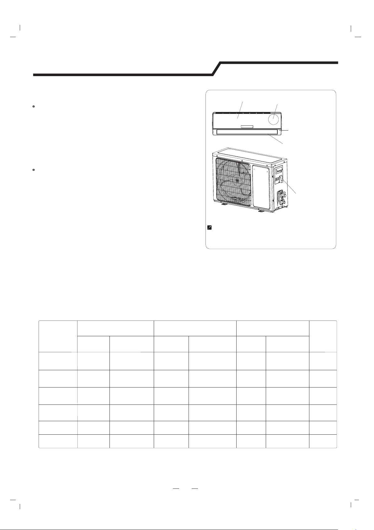
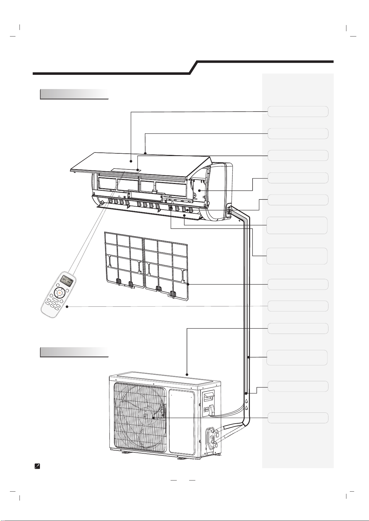
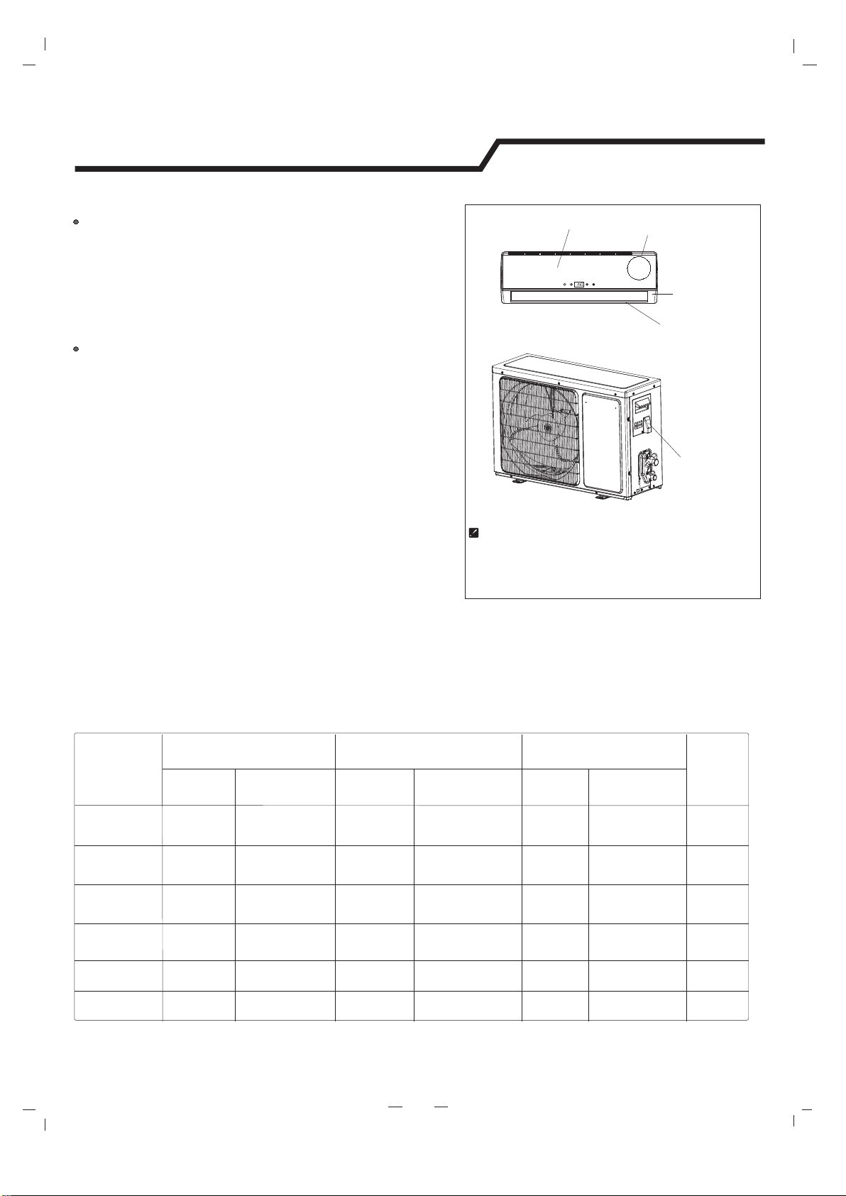
The figures in this manual are based on the external view of a standard model.
Consequently, the shape may differ from that of the air conditioner you have selected.
Air Intake
Air Outlet
Air Outlet
Louver
Vertical Adjustment
Louver
Horizontal Adjustment
Air Filter
Remote Controller
Connection Cord
Pipes and Power
Drain Hose
Emergency Panel
Display Panel
Note: Condensate water drains
at COOLING or DRY operation.
Identification of parts
4
Indoor unit
Outdoor unit
Air Intake
Front Panel
O
N
O
F
F
M
ODE
SMART
QUIET
D
IMMER
ECONO MY
FEEL
SUPER
FAN SPEED
CLOCK
TIMER O N
TIMER O FF
S
LEEP
TEMP.
TEMP.
5
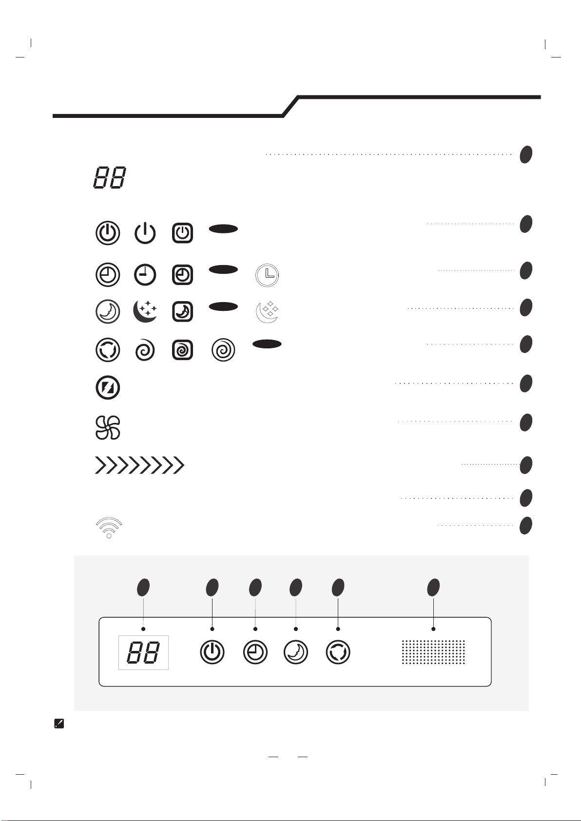
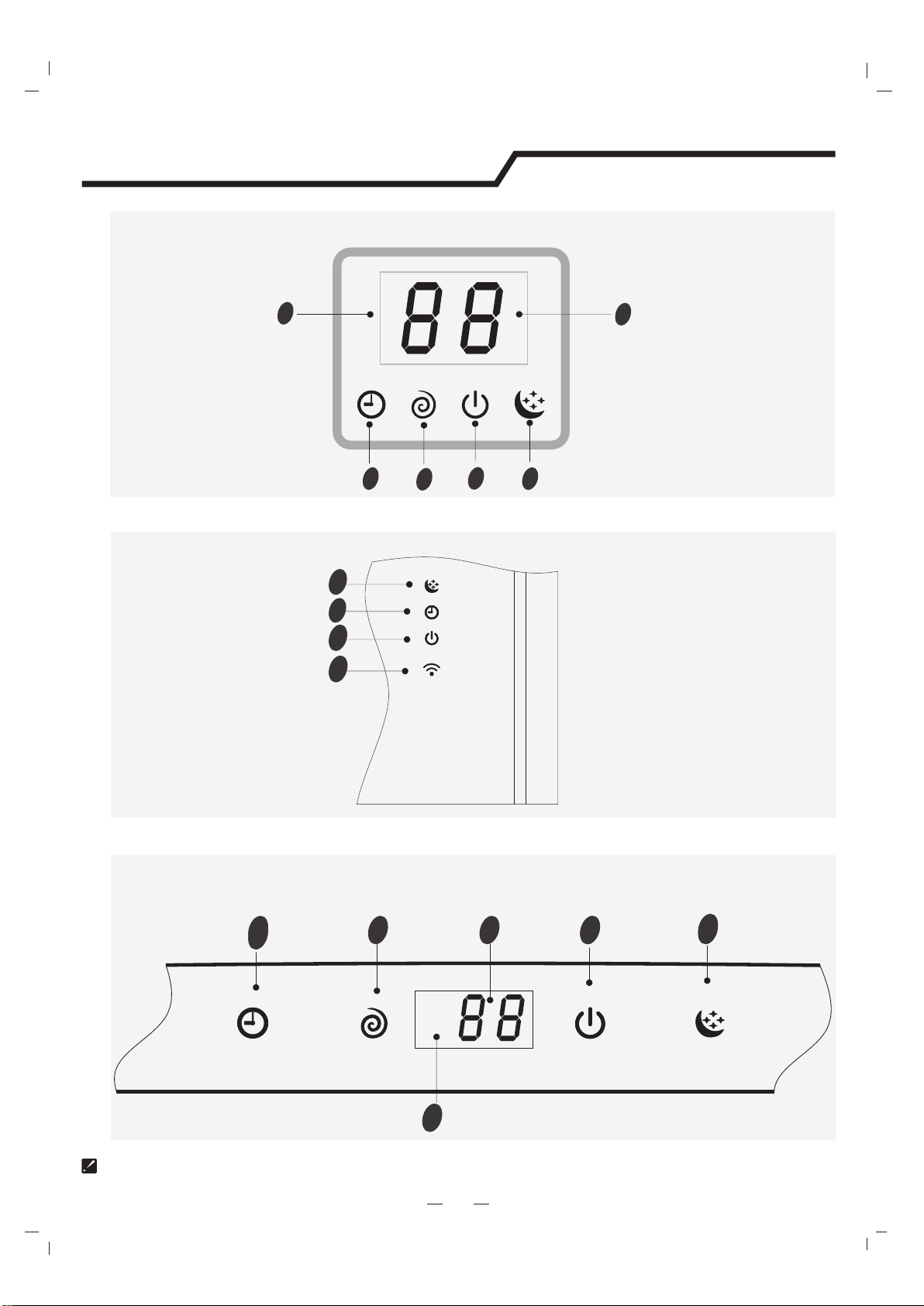
The symbols may be different from these models, but the functions are similar.
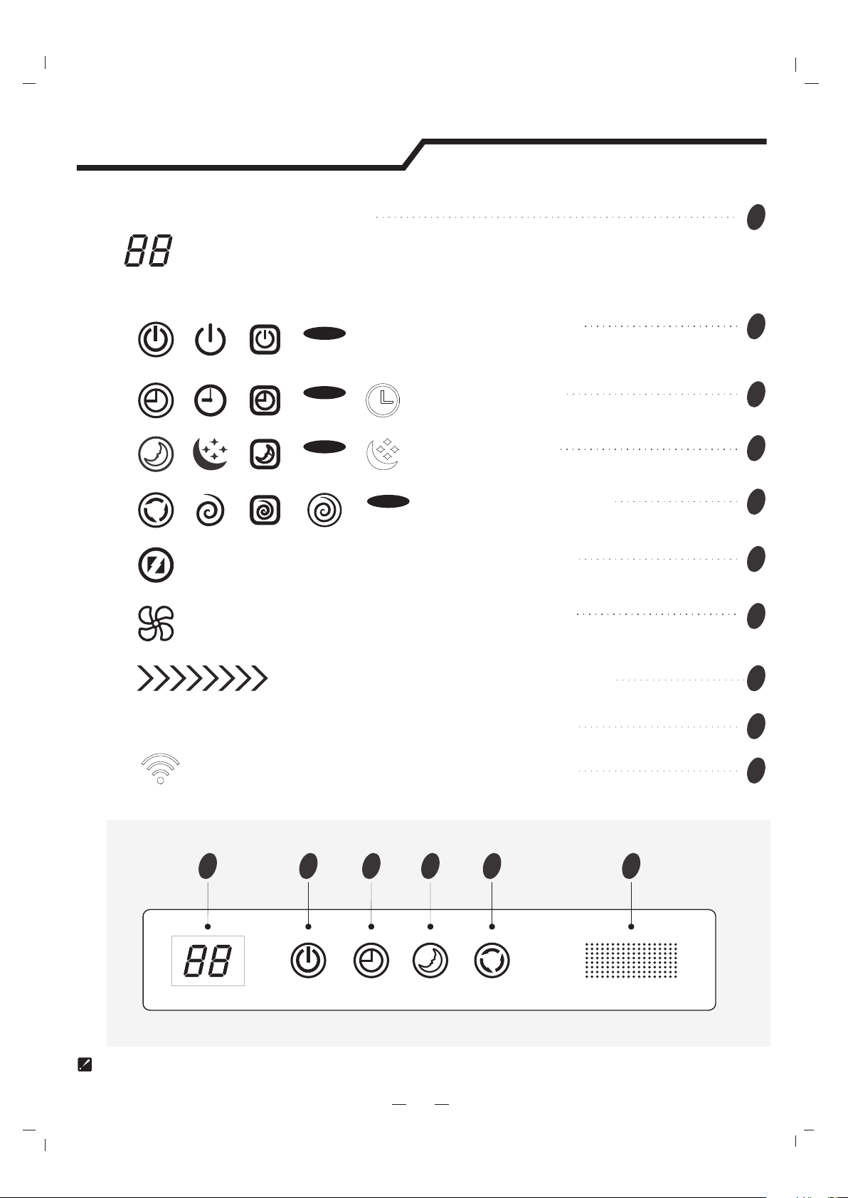
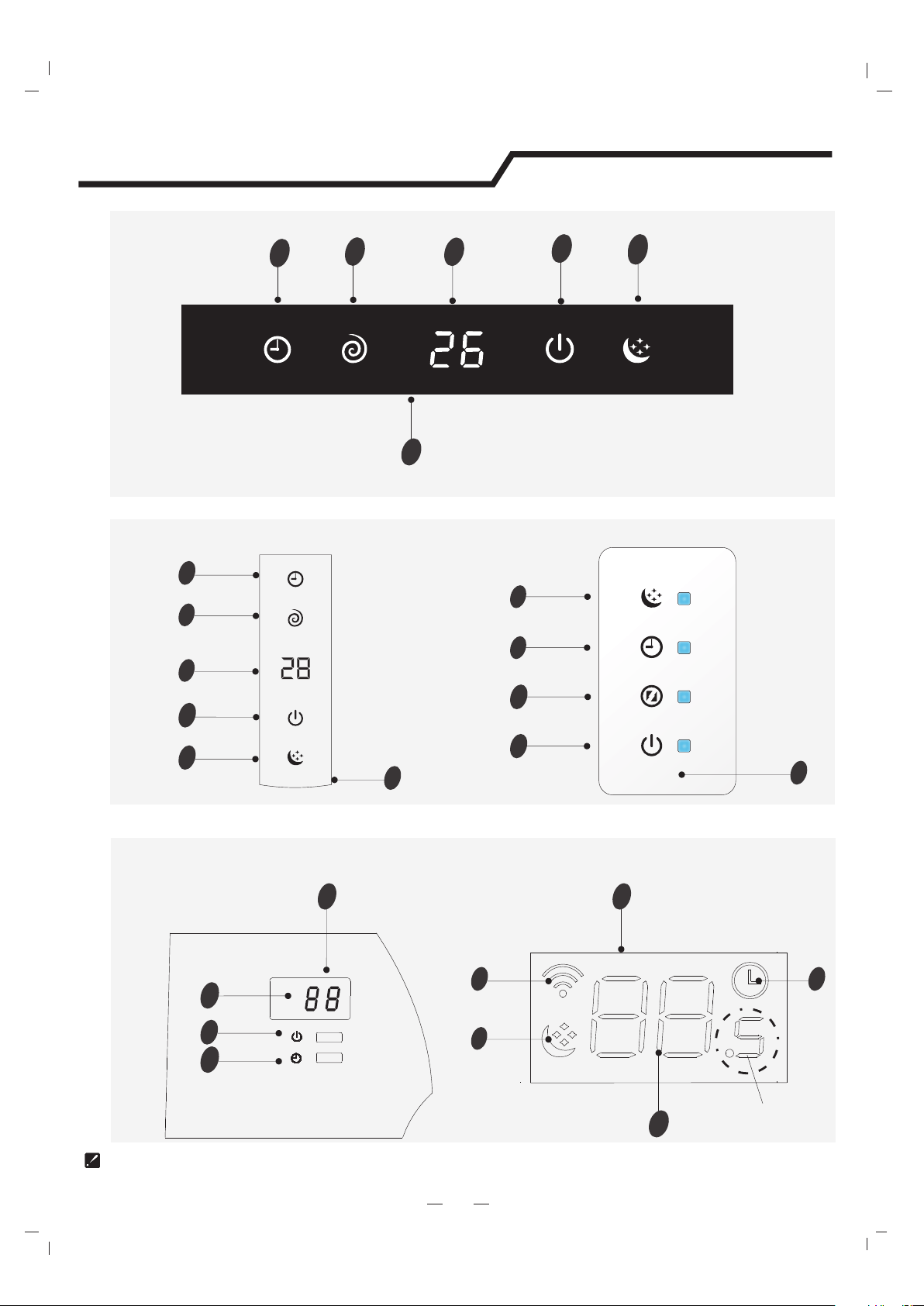
Display introduction
123459
VG/VL series
Display set temperature.
It shows FC after 200 hours of usage as reminder to clean the filter.
After filter cleaning press the filter reset button located on the indoor unit behind the front
panel in order to reset the display.(optional)
Temperature indicator
Timer
Comp.
Run
Sleep
1
Running indicator
It lights up when the AC is running.
It flashes during defrosting.
Timer indicator
It lights up during set time.
Sleep indicator
It lights up in sleep mode.
Compressor indicator
It lights up when the compressor is on.
Super indicator
It lights up in super mode.
2
3
4
5
6
Signal Receptor
9
Smart WIFI indicator
10
Mode indicator
Heating displays orange,others display white
It lights up during WIFI is on.
7
Fan speed indicator
8
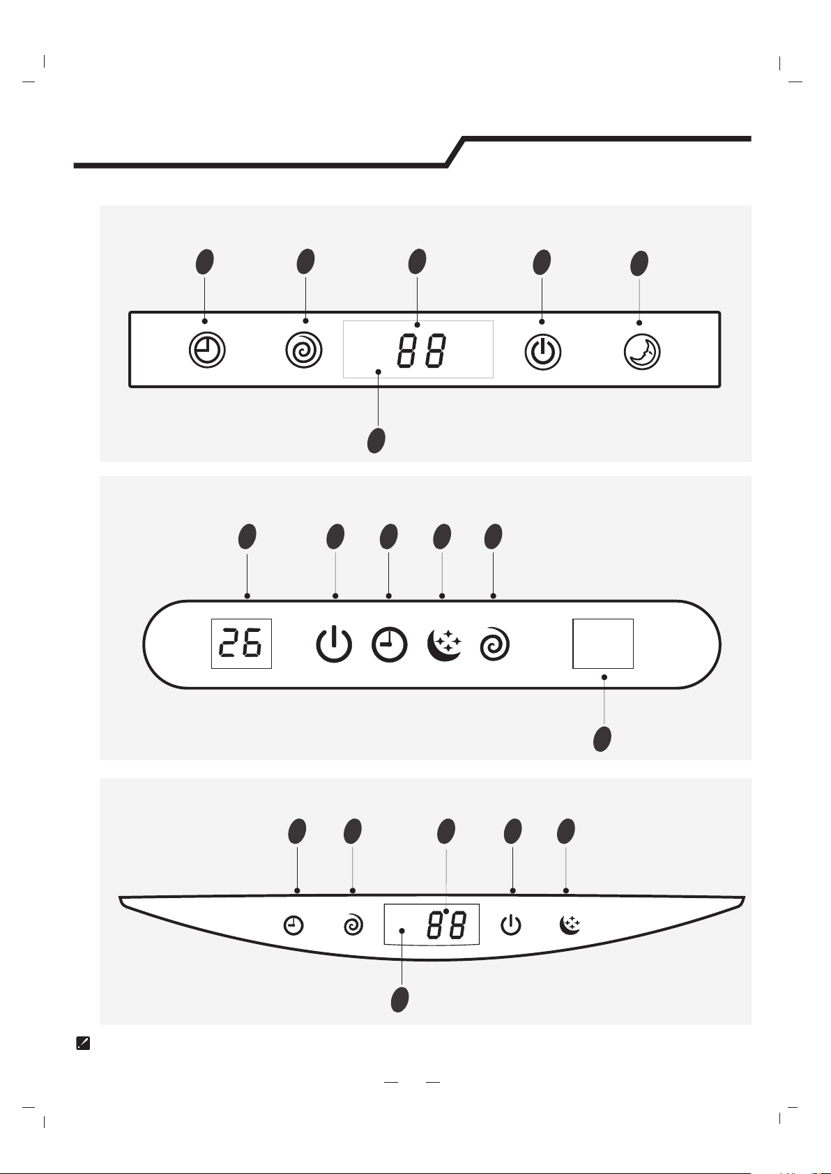
Display introduction
5
1
2
3
4
5
9
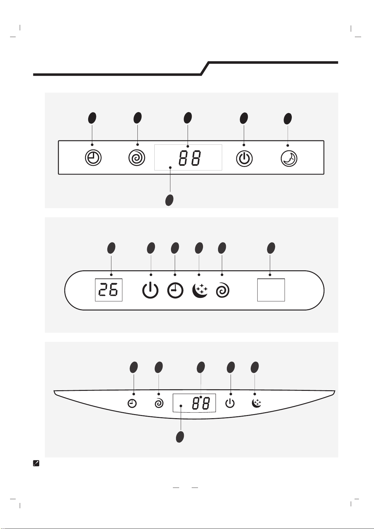
VT series
SF series/DG(Right side)
12345
SE series
12345
9
9
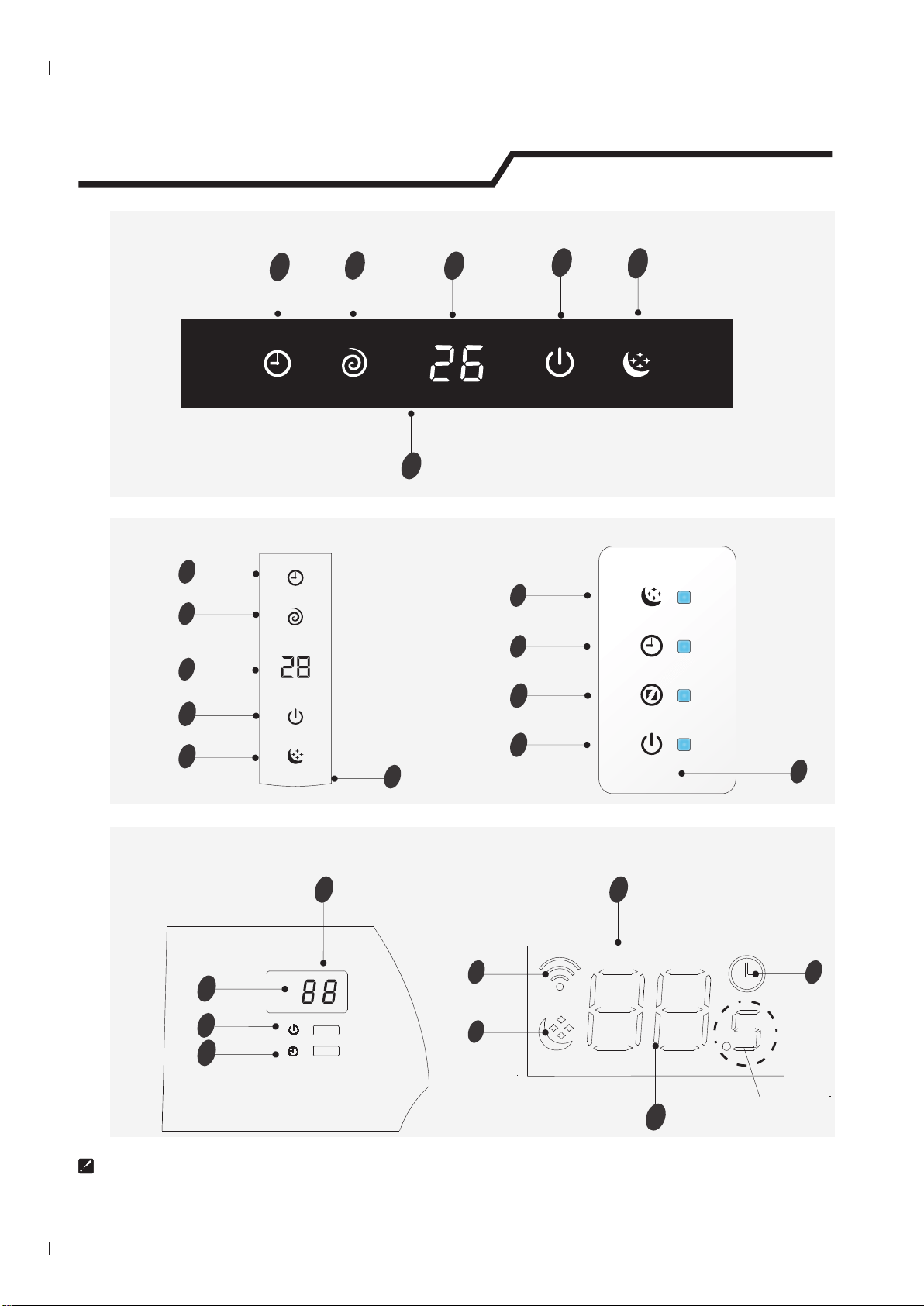
The symbols may be different from these models, but the functions are similar.
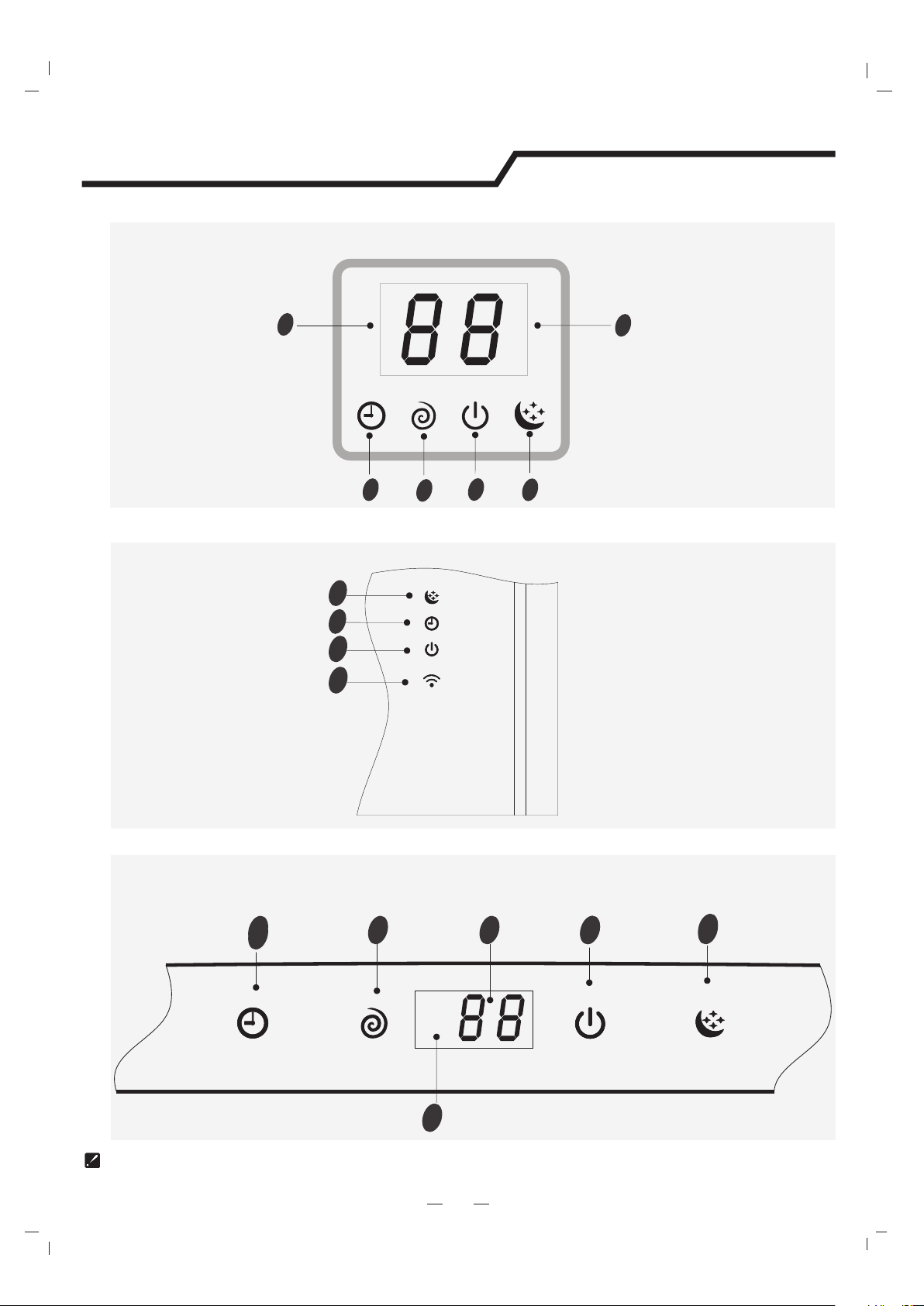
Display introduction
5
The symbols may be different from these models, but the functions are similar.
NT series
VQ/TE/TF/DA/DG(Middle)/DH series
2
3
4
12345
4
3
2
9
2
3
4
5
1
NS/DE series
9
9
Display introduction
5
1
10
4
3
TA/TC seriesTQ/TR series
2
3
9
19
optional
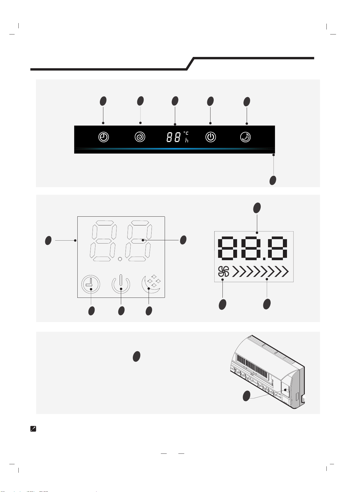
The symbols may be different from these models, but the functions are similar.
VM series
9
22
3
4
4
1
5
NM/DF seriesNK series
2
3
5
4
1
9
6
4
2
3
9
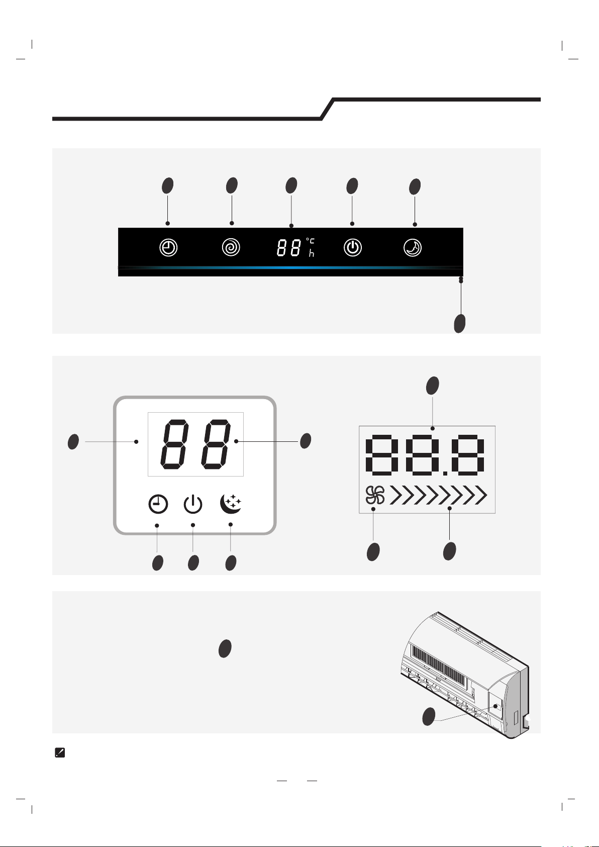
VC series
1
2
3
4
5
Timer
Comp.
Run
Sleep
9
Emergency button
11
11
5
Display introduction
ON/OFF
To let the AC run or stop by pressing the button.
VC series
1
2
3
4
5
Timer
Comp.
Run
Sleep
9
SA/TD/TG/DB/DC/DJ/DK series
9
1
2
3
4
SC series
7
28
1
The symbols may be different from these models, but the functions are similar.
6
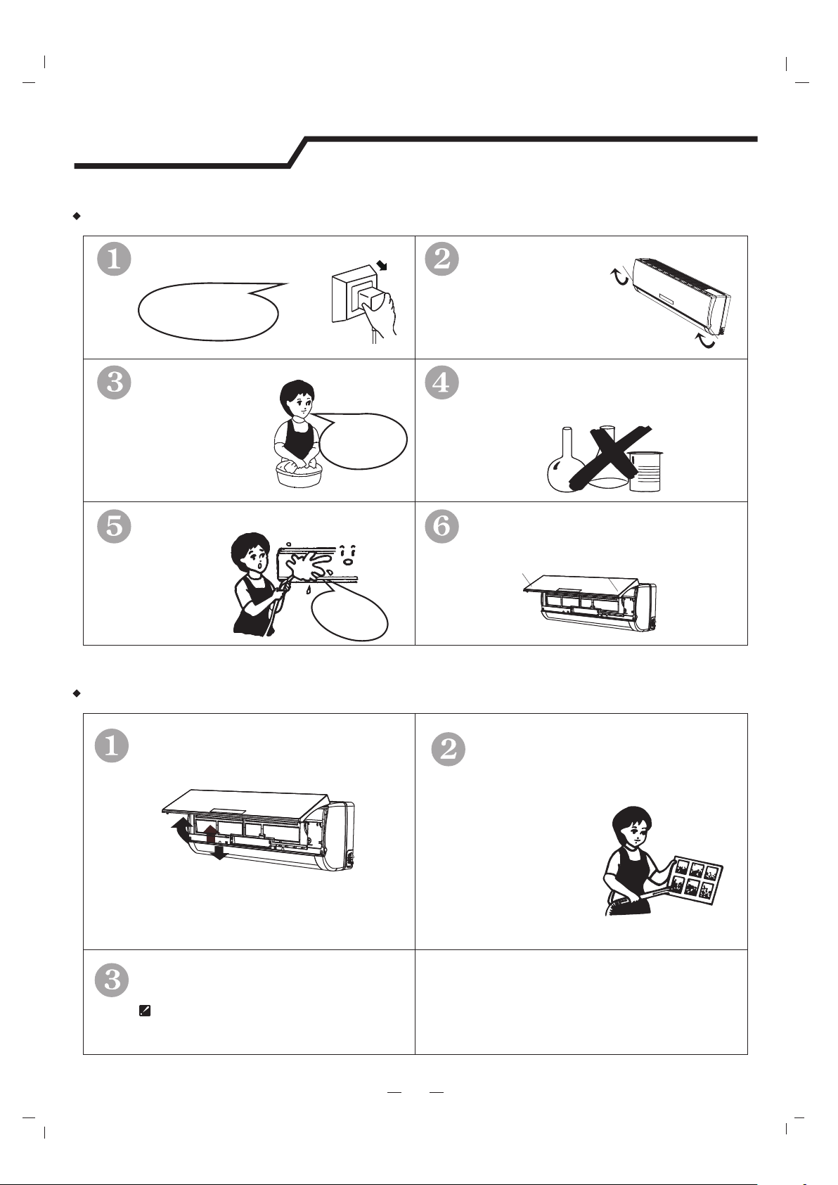
Maintenance
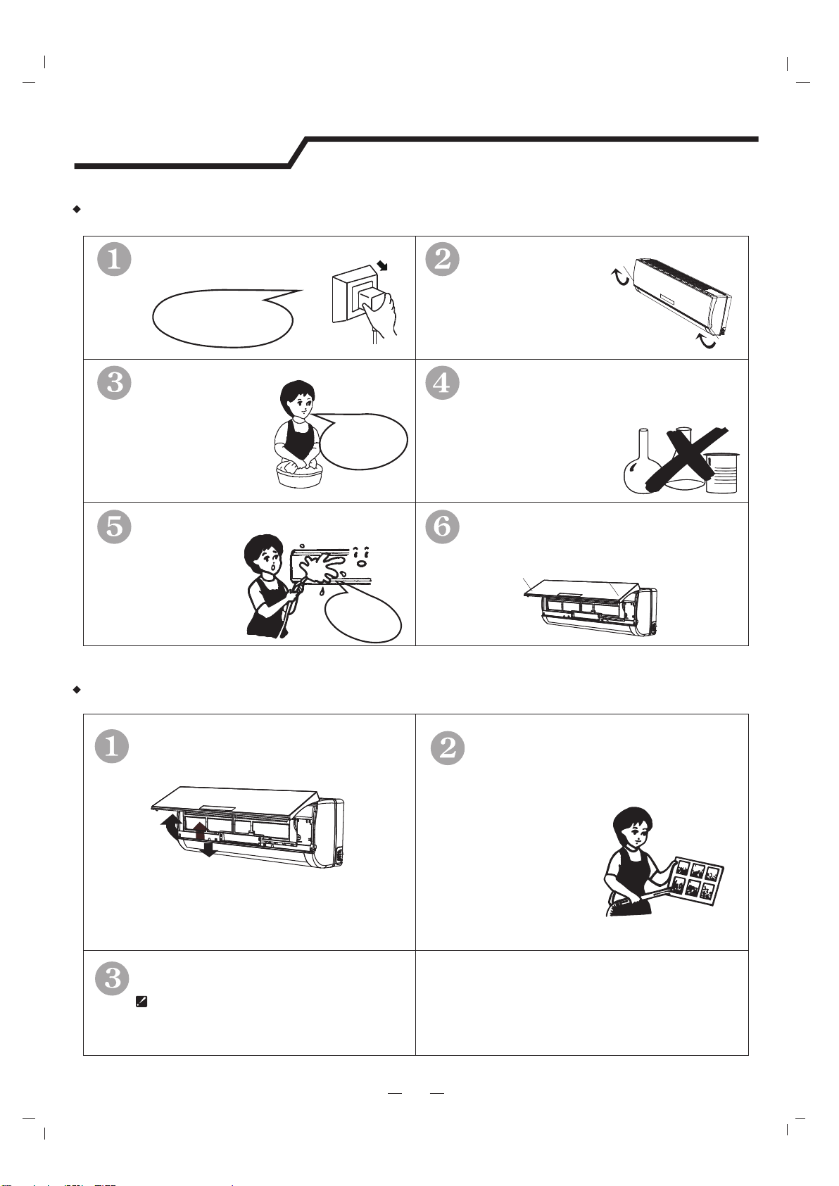
It is necessary to clean the air filter
after using it for about 100 hours.
Front panel maintenance
Air filter maintenance
Never use volatile substance
such as gasoline or polishing
powder to clean the appliance.
Clean and reinstall the air filter.
Close the front panel again.
shock!
Electric
Dangerous!
Wipe with a soft
and dry cloth.
Use soft moisture cloth
to clean if the front panel
is very dirty;
Never sprinkle water onto the
indoor
unit
Reinstall and shut the front panel.
Reinstall and shut the front panel by
pressing position "b" downward.
If the dirt is conspicuous,
wash it with a solution of
detergent in lukewarm water.
After cleaning, dry well in
shade.
Clean the air filter every two weeks
if the air conditioner operates in an
extremely dusty environment.
Stop the appliance, c
power supply and remove the air
filter.
ut off the
1
2
3
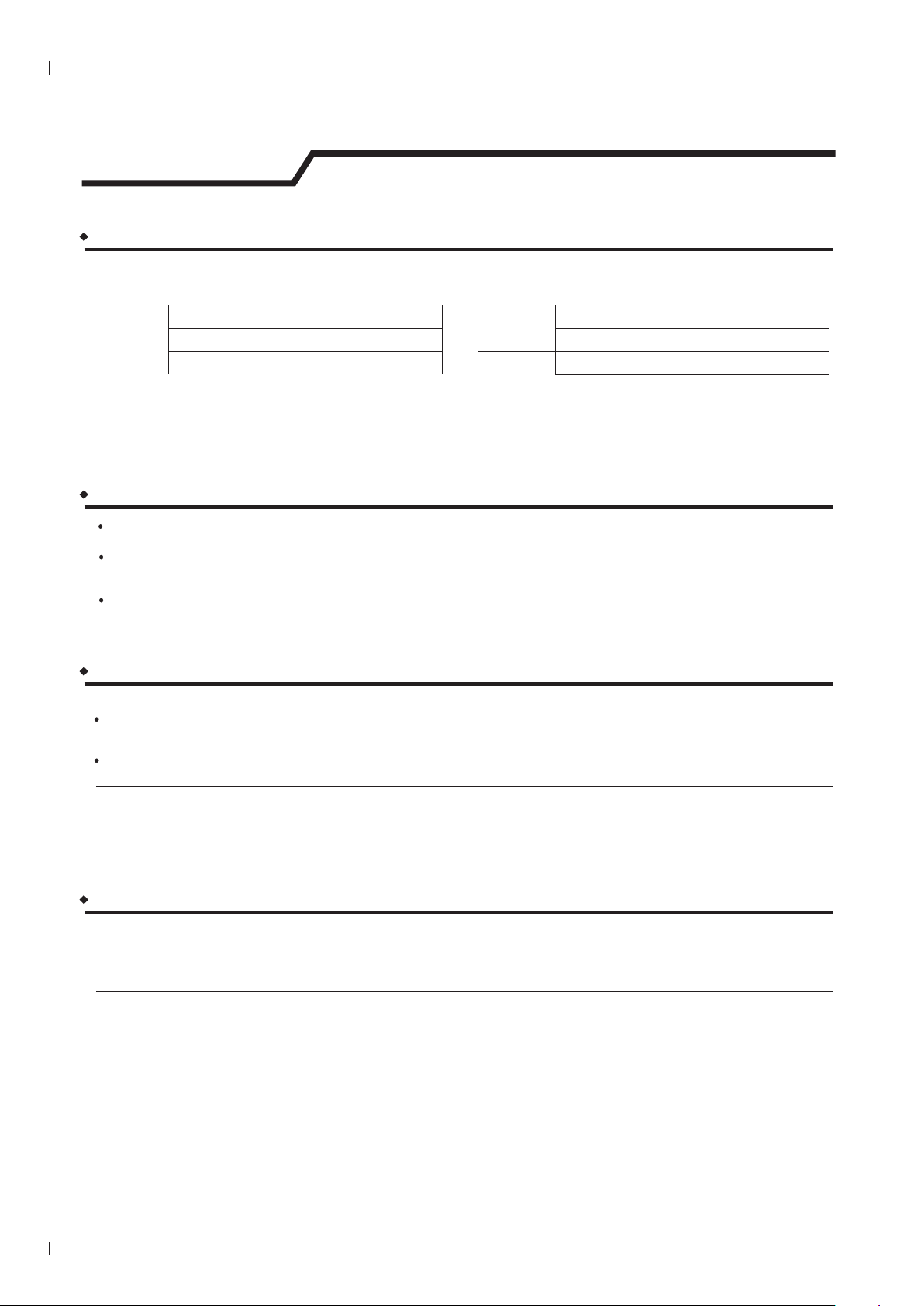
1.Open the front panel.
2.Press the handle of the filter gently
from the front.
3.Grasp the handle and slide out the filter.
soft cloth to
clean it.
Use a dry and
b
b
Turn off the appliance
first before disconnecting
from power supply.
Cut off the power supply
Grasp position "a" and
pull outward to remove the
front panel.
a
a
7
Protection
Operating condition
The protective device maybe trip and stop the appliance in the cases listed below.
HEATING
o
Outdoor air temperature is over 24 C
COOLING
DRY
o
Outdoor air temperature is below -7 C
o
Room temperature is over 27 C
o
Outdoor air temperature is over *43 C
o
Room temperature is below 21 C
o
Room temperature is below 18 C
*For Tropical (T3) Climate condition models, the temperature point is 55℃instead of 43℃.
The temperature of some products is allowed beyond the range. In specific situation, please consult the merchant.
If the air conditioner runs in COOLING or DRY mode withdoor or window opened for a long time when relative
humidity is above 80%,dew may drip down from the outlet.
Noise pollution
Install the air conditioner at a place that can bear its weight in order to operate more quietly.
Install the outdoor unit at a place where the air discharged and the operation noise would not annoy
your neighbors.
Do not place any obstacles in front of the air outlet of the outdoor unit lest it increases the noise level.
Features of protector
If all operation has stopped, press ON/OFF button again to restart, Timer should be set again if it has
been canceled.
The protective device will work at following cases.
Restarting the unit at once after operation stops or changing mode during operation, you need to wait for
3 minutes.
Connect to power supply and turn on the unit at once, it may start 20 seconds later.
Features of HEATING mode
Preheat
Defrost
At the beginning of the HEATING operation, the airflow from the indoor unit is discharged 2-5 minutes later.
In HEATING operation the appliance will defrost (de-ice) automatically to raise efficiency.
This procedure usually lasts 2-10 minutes. During defrosting, fans stop operation.
After defrosting completes, it returns to HEATING mode automatically.
Note: Heating is NOT available for cooling only air conditioner models.
1.
2.
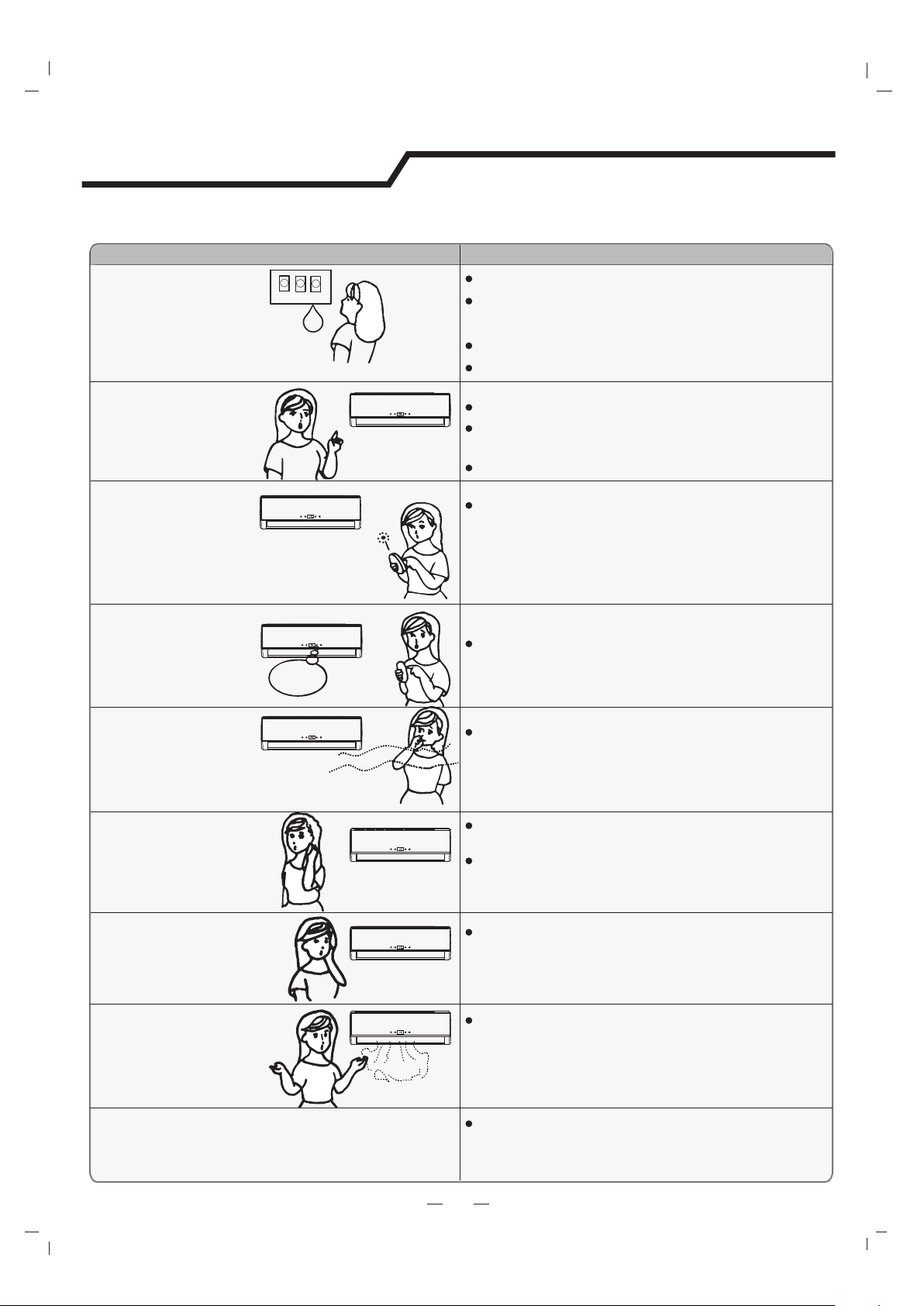
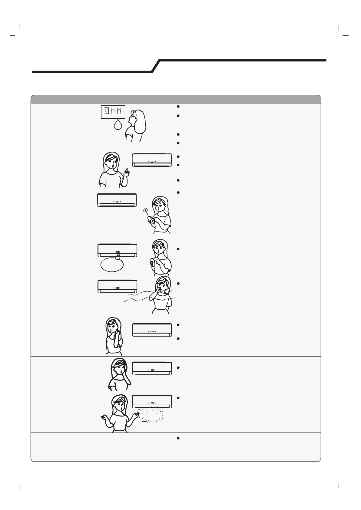
TroubleAnalysis
Does not run
No cooling or
heating air
Ineffective control
Does not operate
immediately
Peculiar odor
A sound of
flowing water
Cracking sound is
heard
Spray mist from
the outlet
The compressor indicator(red) lights on constantly,
and indoor fan stops.
The unit is shifting from heating mode to defrost.
The indicator will lights off within ten minutes and
returns to heating mode.
Is the air filter dirty?
Are the intakes and outlets of the air
conditioner blocked?
Is the temperature set properly?
don't run
If the protector trip or fuse is blown.
If the plug is not properly plugged.
If batteries in the remote controller exhausted.
Please wait for 3 minutes and start again,
protector device may be preventing unit to work.
.
The following cases may not always be a malfunction, please check it before asking for service.
If strong interference(from excessive static
electricity discharge, power supply voltage
abnormality)presents, operation will be
abnormal. At this time, disconnect from the
power supply and connect back 2-3 seconds later.
Changing mode during operation, 3 minutes
will delay.
This odor may come from another source
such as furniture, cigarette etc, which is
sucked in the unit and blows out with the air.
Caused by the flow of refrigerant in the
air conditioner, not a trouble.
Defrosting sound in heating mode.
The sound may be generated by the expansion
or contraction of the front panel due to change
of temperature.
Mist appears when the room air becomes
very cold because of cool air discharged
from indoor unit during COOLING or DRY
operation mode.
8
Troubleshooting
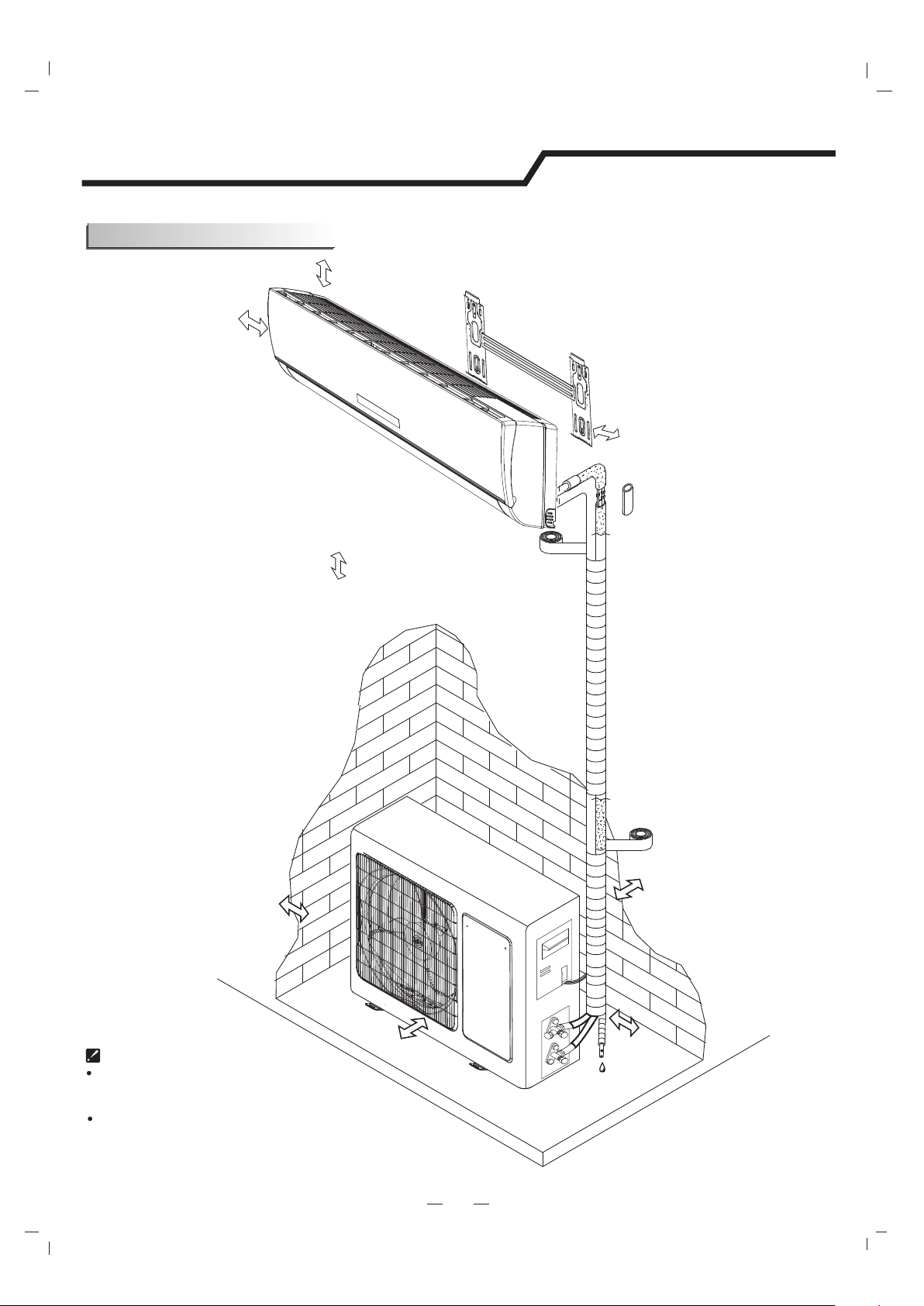
9
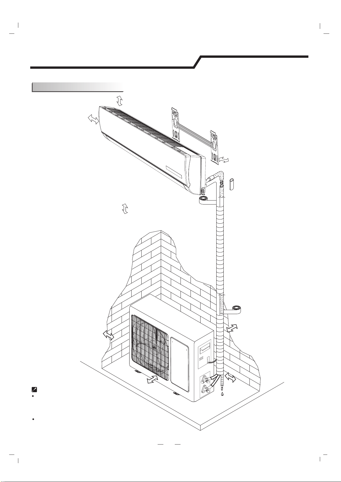
Distance from ceiling
Distance from wall
should be over 50mm
Distance from the wall
Air intake distance from
the wall should be
over 250mm
Air intake distance from the wall
over 250mm
air outlet distance from the wall
should be over 500mm
should be over 200 mm
should be over 50mm
Distance from floor
over 2500mm.
should be
should be over 250mm
Installation instructions
Installation diagram
Installation must be performed in accordance with
the national wiring standards by authorized personnel only.
Above figure is only a simple presentation
of the unit, it may not match the external
appearance of the unit you purchased.
Outdoor unit
Outdoor unit
Indoor unit
Indoor unit
Pipe length is
15 meters Max.
Pipe length is
15 meters Max.
be less than 5m
be less than 5m
Height should
Height should
10
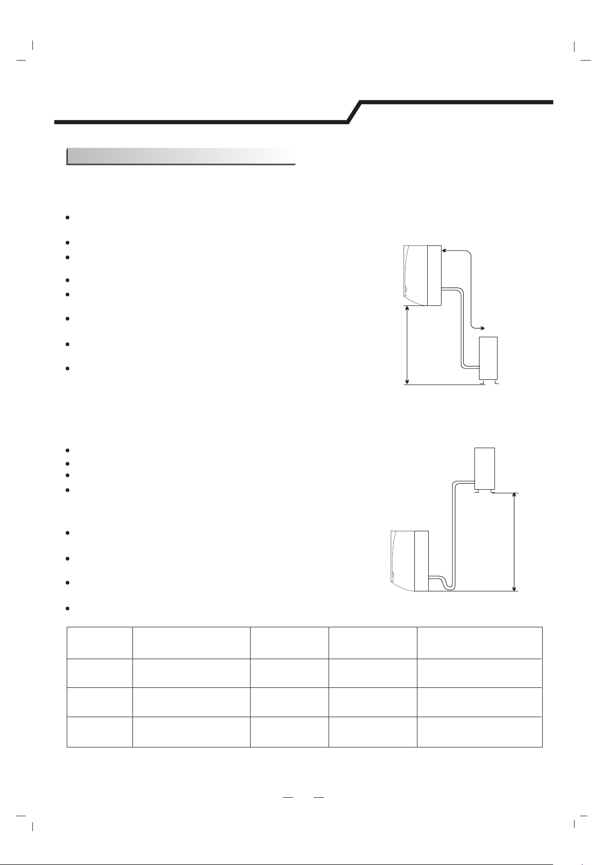
Installation instructions
Select the installation location
Location for Installing Outdoor Unit
Where it is convenient to install and well ventilated.
Avoid installing it where flammable gas could leak.
Keep the required distance apart from the wall.
The distance between Indoor and outdoor unit should
be 5 meters and can go up to maximum 15 meters
with additional refrigerant charge.
Keep the outdoor unit away from a place of greasy dirt,
vulcanization gas exit.
Avoid installing it at the roadside where there is a risk of
muddy water.
A fixed base where is not subject to increasing operation
noise.
Where there is not any blockage for air outlet.
If the height or pipe length is out of the scope of the table, please consult the merchant.
Location for Installing Indoor Unit
Where there is no obstacle near the air outlet and air can be
easily blown to every corner.
Where piping and wall hole can be easily arranged.
Keep the required space from the unit to the ceiling and wall
according to the installation diagram on previous page.
Where the air filter can be easily removed.
Keep the unit and remote controller 1m or more apart from
television, radio etc.
To prevent the effects of a fluorescent lamps, keep as far as
possible.
Do not put anything near the air inlet to obstruct it from air
absorption.
Where there is strong enough to bear the weight
and is not tend to increase operation noise and vibration.
Model
5K~18K
5
15
5
20
Max. Allowable Tubing
Length at Shipment (m)
Limit of Tubing
Length (m)
Limit of Elevation
Difference H (m)
Required amount of
additional refrigerant (g/m)
22K.24K
28K.30K.36K
5
15
5
30
5
15
5
40
Piping direction
1
2
3
4
trough
Note: When installing the pipe at the directions
1,2 or 4, saw the corresponding unloading piece
off the indoor unit base.
Unloading
piece
Saw the unloading piece
off along the trough
Put the piping (liquid and gas pipe) and cables through the wall hole from outside or put them through
from inside after indoor piping and cables connection complete so as to connect to outdoor unit.
Decide whether saw the unloading piece off in accordance with the piping direction.(as shown below)
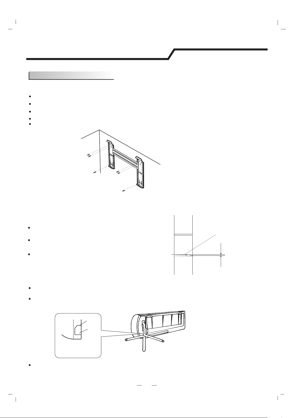
3. Indoor Unit Piping Installation
11
Installation instructions
Indoor
Outdoor
Wall hole sleeve
( hard polythene tube
prepared by user)
5mm
(tilt downward)
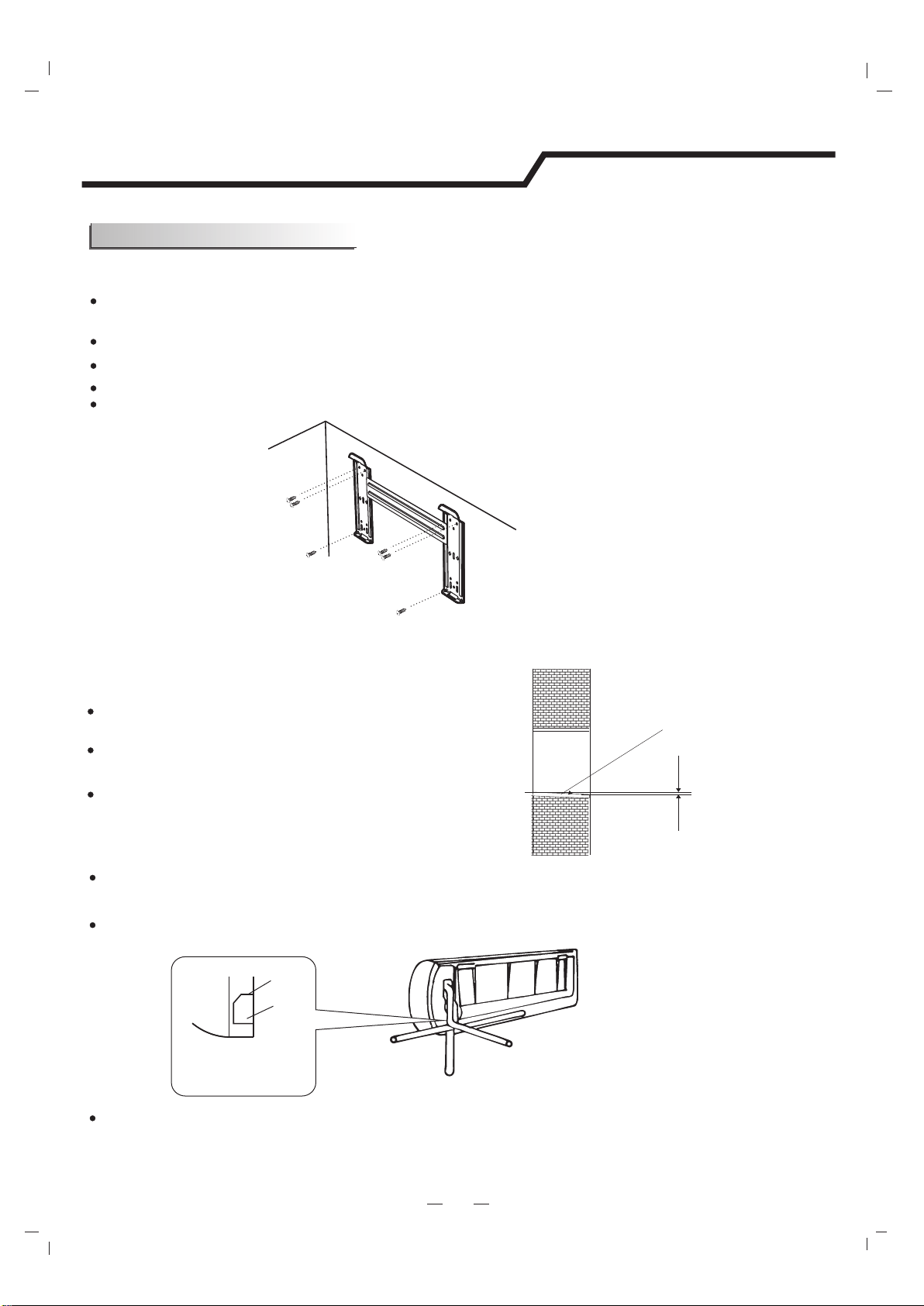
Install a sleeve through the wall hole to keep the wall
tidy and clean.
Drill a hole on the wall. The hole should tilt a little
downward toward outside.
Decide the position of hole for piping according to the
location of mounting plate.
2. Drill a Hole for Piping
. Keep the mounting plate horizontally with a horizontal ruler or dropping line.
Drill holes of 32mm in depth on the wall for fixing the plate.
Insert the plastic plugs to the hole, fix the mounting plate with tapping screws.
Inspect if the mounting plate is well fixed. Then drill a hole for piping.
1. Installing the Mounting Plate
Decide an installing location for the mounting plate according to the indoor unit location and piping direction.
Indoor unit installation
After connecting piping as required, install the drain hose. Then connect the power cords. After connecting,
wrap the piping, cords and drain hose together with thermal insulation materials.
Mounting plate
Tapping screw
Note: The shape of your mounting plate may be different from the one above, but the installation method is similar.
Note: As the above figure shown, the six holes matched with tapping screw on the mounting plate must be used to
fix the mounting plate, the others are prepared.
Installation instructions
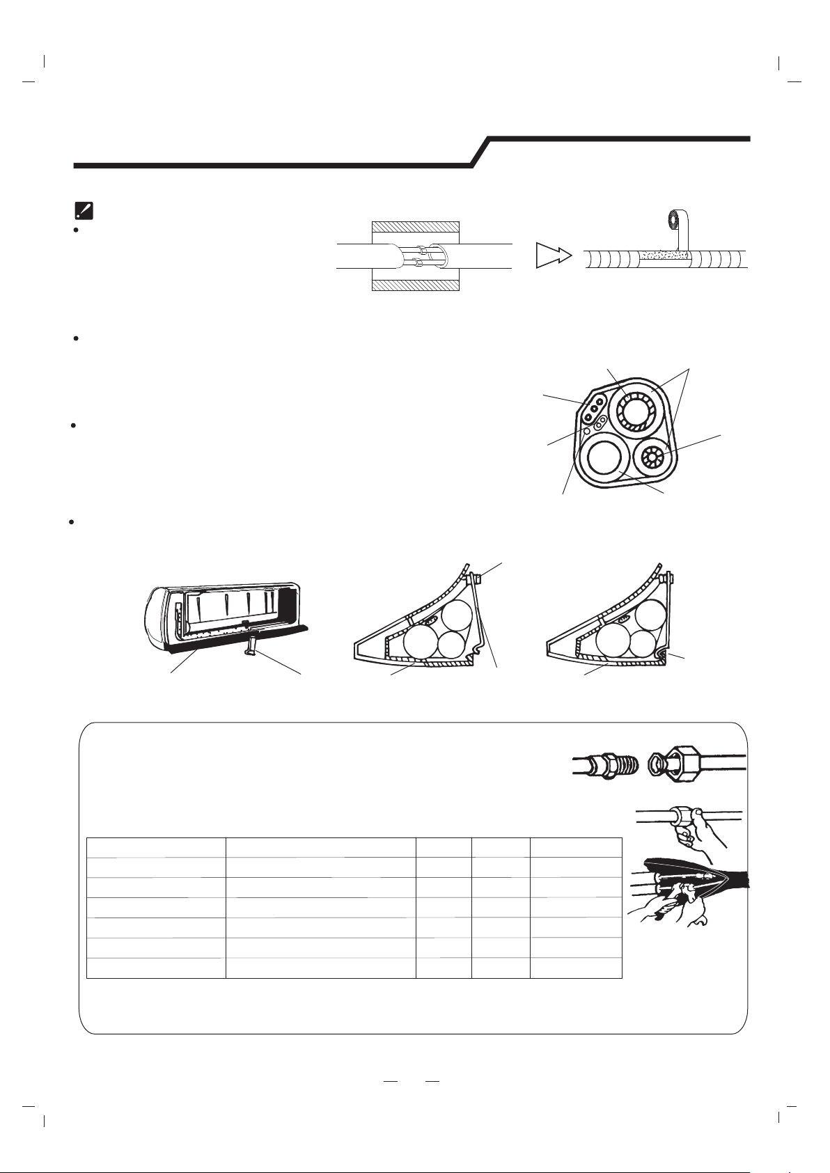
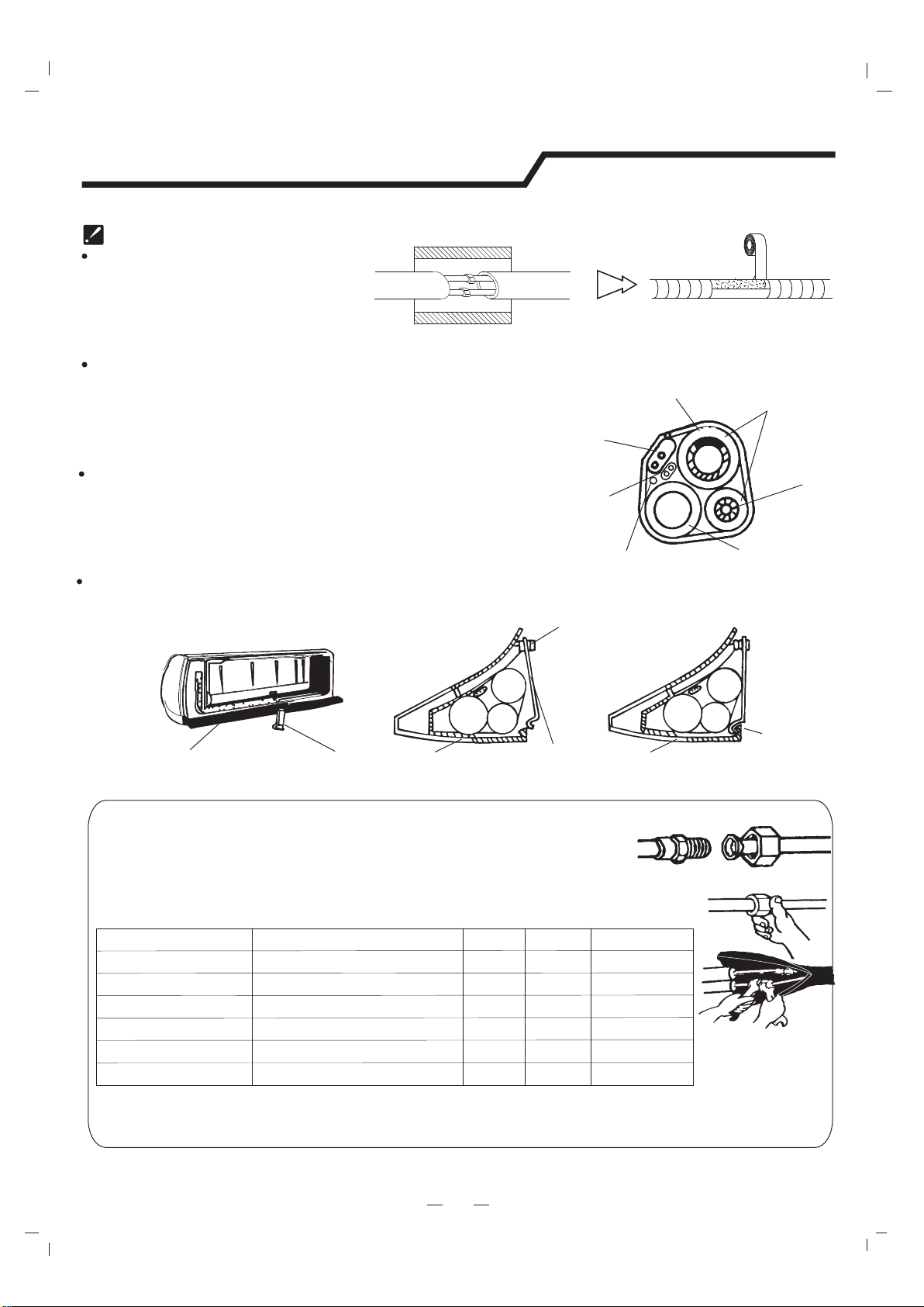
Piping Joints Thermal Insulation:
Wrap the piping joints with thermal
insulation materials and then wrap
with a vinyl tape.
Piping Thermal Insulation:
a. Place the drain hose under the piping.
b. Insulation material uses polythene foam over 6mm in thickness.
Note: Drain hose is prepared by user.
Drain pipe should point downward for easy drain flow.
Do not arrange the drain pipe twisted, sticking out or wave
around, do not immerse the end of it in water.
If an extension drain hose is connected to the drain pipe, make
sure to thermal insulated when passing along the indoor unit.
When the piping is directed to the right, piping, power
Cord and drain pipe should be thermal insulated and
fixed onto the back of the unit with a piping fixer.
Thermal insulation
wrapped with vinyl type
Small
pipe
Large pipe
Thermal insulation
tube
Power cord 1
(for heat-pump)
Power cord
Defrost cable(for heat-pump)
Drain hose
(prepared by user)
A. Insert the pipe fixer to the slot.
B. Press to hook the pipe fixer onto the base.
Base
Base
Base
Piping fixer
Piping fixer
Hook here
Insert here
drain
hose
drain
hose
large
pipe
large
pipe
small
pipe
small
pipe
12
*The unit of 18K*,24K*,36K* is bigger than the unit of 18K,24K,36K.
b. Pre-tighten them with fingers at first, then use the wrenches.
a. Connect indoor unit pipes with two wrenches. Pay special attention
to the allowed torque as shown below to prevent the pipes, connectors
and flare nuts from being deformed and damaged.
Piping Connection:
Pipe size
Model
Liquid Side (1/4 inch) φ6mm or
5,7,8,9,10,12,14,15,18,24K
12,14,15,18K
18K*,22,24K*,28,30,36K
18K*,22,24,28,30,36K
36K*
5,7,8,9,10K
15~20N·m
17mm
0.5mm
0.6mm
0.6mm
0.6mm
0.6mm
22mm
24mm
22mm
27mm
30~35N·m
30~35N·m
50~55N·m
60~65N·m
Liquid Side (3/8 inch)φ9.53mm or
Gas Side ( inch)φ12mm or 1/2
Gas Side (3/8 inch)φ9.53mm or
Gas Side (5/8 inch)φ16mm or
Torque
Nut widthMin.thickness
1.0mm
32mm
70~75N·m
Gas Side (3/4 inch)φ19mm or
4. Connecting of the Cable
Outdoor Unit
Indoor Unit
Connect the power connecting cord to the indoor unit
by connecting the wires to the terminals on the control
board individually in accordance with the outdoor unit
connection.
Note: For some models, it is necessary to remove the cabinet to
connect to indoor unit terminal.
Installation instructions
Caution:
1. Never fail to have an individual power circuit specifically for the air conditioner. As for the method of
wiring, refer to the circuit diagram posted on the inside of the access door .
2.Comfirm that the cable thickness is as specified in the power source specification.
3.Check the wires and make sure that they are all tightly fastened after cable connection.
4. Be sure to install an earth leakage circuit breaker in wet or moist area.
13
The figures in this manual are based on the external
view of a standard model. Consequently, the shape
may differ from that of the air conditioner you have
selected.
Access door
Terminal(inside)
Outdoor unit
1). Remove the access door from the unit by loosening
the screw. Connect the wires to the terminals on the
control board individually as the following.
2). Secure the power connecting cord onto the control
board with cable clamp.
3). Reinstall the access door to the original position
with the screw.
4) Use a recognized circuit breaker for 24K model or above
between the power source and the unit.
A disconnecting device to adequately disconnected all
supply lines must be fitted.
Cable Specifications
2
2
The cord may be different from the list above. It may be used as the next list. And it can be larger.
0-7A, use 0.75mm or 18AWG. 0-10A, use 1mm or 16AWG. 0-16A, use 1.5mm or 14AWG.
0-20A, use 2.5mm or 14AWG. 0-25A, use 2.5mm or 12AWG. 0-32A, use 4mm or 12AWG.
2
2
2
2
Chassis
Cabinet
Front panel
Terminal (inside)
Indoor unit
Capacity
(Btu/h)
To indoor
H07RN-F
Power connecting cord
Power cord
Type Type Type
Normal cross
- sectional area
Main
power
supply
Normal cross
- sectional area
Normal cross
- sectional area
Power connecting cord1
2
2.5mm X3
To indoor
To outdoor
2
1.5~2.5mm X3
5K~13K
H05VV-F
2
1.0~1.5mm X3
H05VV-F
H05RN-F
H05RN-F
H05RN-F
2
1.5-2.5mm X3
2
0.75mm X2
(Heat-pump)
2
0.75mm X2
(Heat-pump)
2
0.75mm X3
(Heat-pump)
H07RN-F
H05RN-F
H07RN-F
2
1.0mm X3
2
1.5mm X3
2
1.0mm X3
2
1.0mm X4Cooling only
To indoor
18K~30K
2
1.5-2.5mm X3
H05VV-F
2
1.5-2.5mm X4
H07RN-F
H07RN-F
2.5~X3
2
4.0mm
To outdoor
24K~36K
H05RN-F
H07RN-F
14K~24K
H05RN-F
2
0.75mm X2
(Heat-pump&Optional)
18K~30K
H07RN-F
1.5X5
2
mm
To outdoor
H05RN-F
2
0.75mm X4
24K~36K
H05RN-F
2
0.75mm X2
(Heat-pump)
H05RN-F
H07RN-F
2
1.0mm X4
2
0.75mm X4
H05RN-F
2
0.75mm X2
(Heat-pump&Optional)
Installation instructions
14
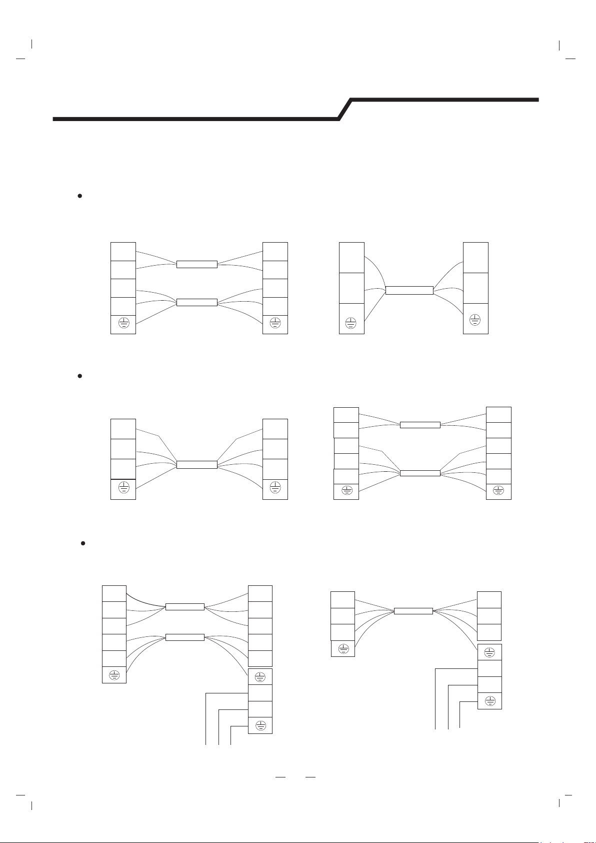
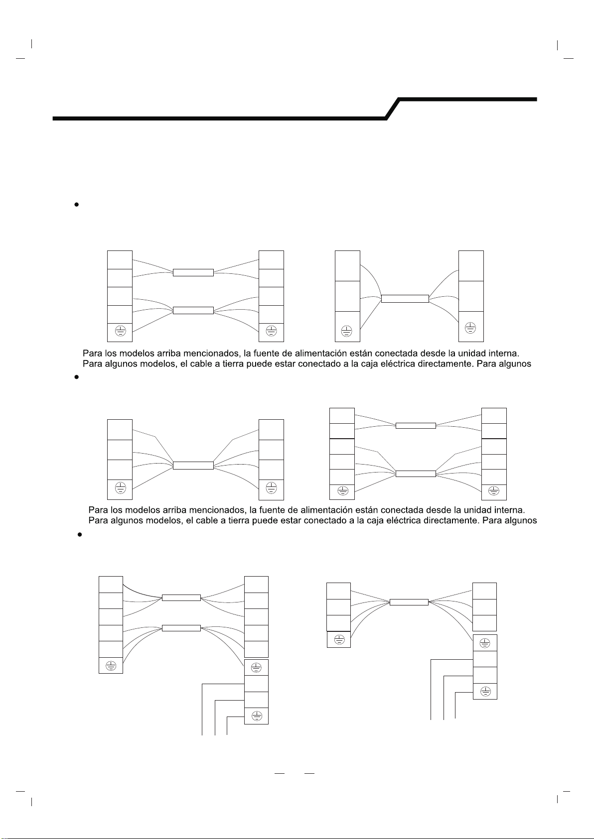
Indoor unitIndoor unit
Outdoor unitOutdoor unit
Indoor unit
For these models, the power supply are connected from outdoor unit, with a circuit breaker.
Indoor unit
Outdoor unitOutdoor unit
Terminal Terminal Terminal Terminal
Terminal
Terminal
N
L
1L1L
3L3L
2L2L
N
N
L
L
Power connecting cord
Power connecting cord
Power supply
Power supply
N
L
1L
1L
N
L
N
L
18K~30K Model
Blue
Y
ellow/Green
Brown
Black
Gray
Brown
Blue
Brown
Gray
Black
Brown
Yellow/Green
Power connecting cord I
Black
Yellow/Green
Gray
Brown
Yellow/Green
Black
Brown
Gray
Indoor unitIndoor unit
Outdoor unitOutdoor unit
Power connecting cord
Power connecting cord
Power connecting cord I
Blue
Blue
Blue
Blue
Blue
Blue
Yellow/Green
Yellow/Green
Yellow/Green
Yellow/Green
Brown
Brown
Brown
Brown
Brown
Brown
NN
2L
NN
2L
1L
1L
1L
1L
3L3L
Terminal Terminal Terminal Terminal
For above models, the power supply are connected from indoor unit.
For these models, the ground wire may be connected to the electric box directly.
18K~30K Model
For above models, the power supply are connected from indoor unit.
For these models, the ground wire may be connected to the electric box directly.
Indoor unit
Outdoor unit
Power connecting cord
Black
Blue
Blue
Black
Yellow/Green
Yellow/Green
Brown
Brown
N
N
1L
1(L)
L
L
Terminal Terminal
Indoor unit
Outdoor unit
Power connecting cord
Black
Blue
Blue
Black
Yellow/Green
Yellow/Green
Brown
Brown
N
N
1L
1L
L
L
Terminal
Terminal
5K~24K Model
Power connecting cord I
Blue
Blue
Brown
Brown
2L2L
3L
3L
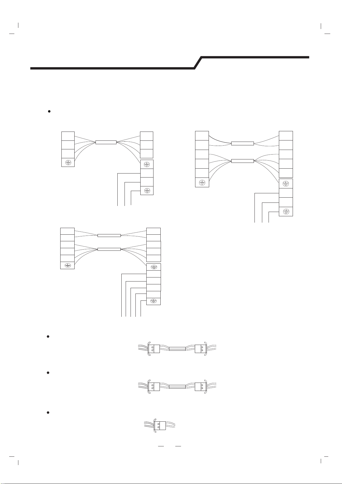
Wiring Diagram
Warning: Before obtaining access to terminals, all supply circuits must be disconnected.
Note: All the wires may be different colors.The indicators ‘1L 2L 3L’ may be ‘4 5 6’ or others.
And the terminal may be defferent from the material object.
Installation instructions
15
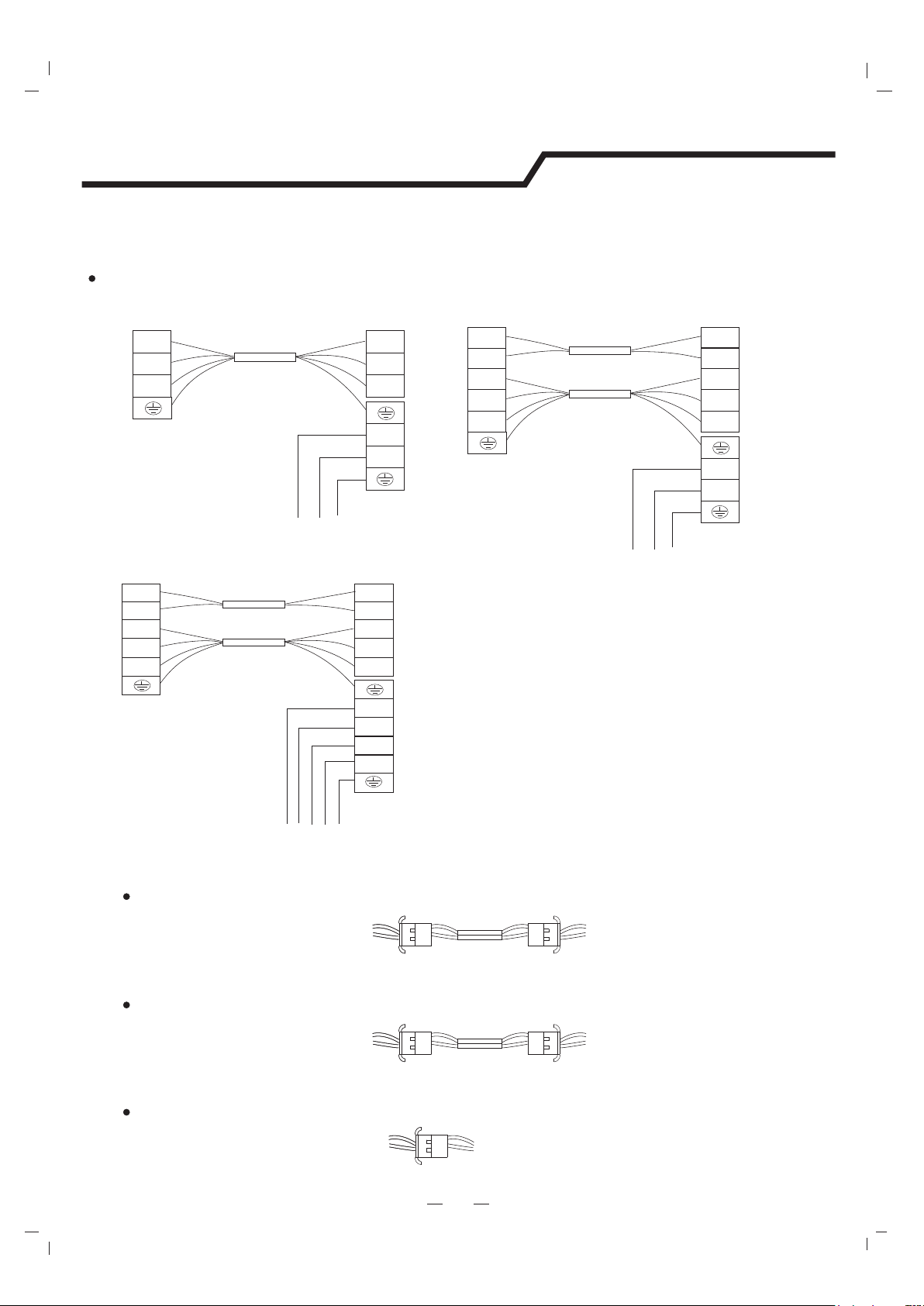
Ionizer () The ionizer is an optional part
After connection, the ionizer will work automatically .
Ionizer wire (indoor)
Defrost wire (indoor)
Sensor(outdoor)
After connection, the defrost wire should be well wrapped with a wrapping tape and the
connector should be put inside the unit.
Defrost cable (for heat-pump air conditioner only ,and it`s an optional part)
Wire (indoor)
Sensor(outdoor)
After connection, the wire should be well wrapped with a wrapping tape and the connector
should be put inside the unit.
Overheat protection or high pressure protection cable (it`s an optional part)
For these models, the power supply are connected from outdoor unit, with a circuit breaker.
All the wires may be different colors.
24K~36K Model
Indoor unit
Outdoor unit
Terminal
Terminal
Terminal
Power connecting cord
Power supply
N
L
1L
1L
N
L
N
L
Black
Yellow/Green
Gray
Brown
Yellow/Green
Black
Brown
Gray
Indoor unit
Outdoor unit
Terminal Terminal
Terminal
Power connecting cord
Power supply
N
L
1L
1L
N
L
N
L
Black
Yellow/Green
Gray
Brown
Yellow/Green
Black
Brown
Gray
Power connecting cord I
Blue
Blue
Brown
Brown
2L2L
3L
3L
Indoor unit
Outdoor unit
Terminal Terminal
Terminal
Power connecting cord
Power supply
N
L
1L
1L
N
L
S
R
Black
Yellow/Green
Gray
Brown
Yellow/Green
Black
Brown
Gray
Power connecting cord I
Blue
Blue
Brown
Brown
2L2L
3L
3L
N
T
And the terminal may be defferent from the material object.
Warning: Before obtaining access to terminals, all supply circuits must be disconnected.
Note:All the wires may be different colors.The indicators ‘1L 2L 3L’ may be ‘4 5 6’ or others.
Fix with bolts and nuts tightly on a flat and strong floor.
If installed on the wall or roof, make sure to fix the supporter well to prevent it
from shaking due to serious vibration or strong wind.
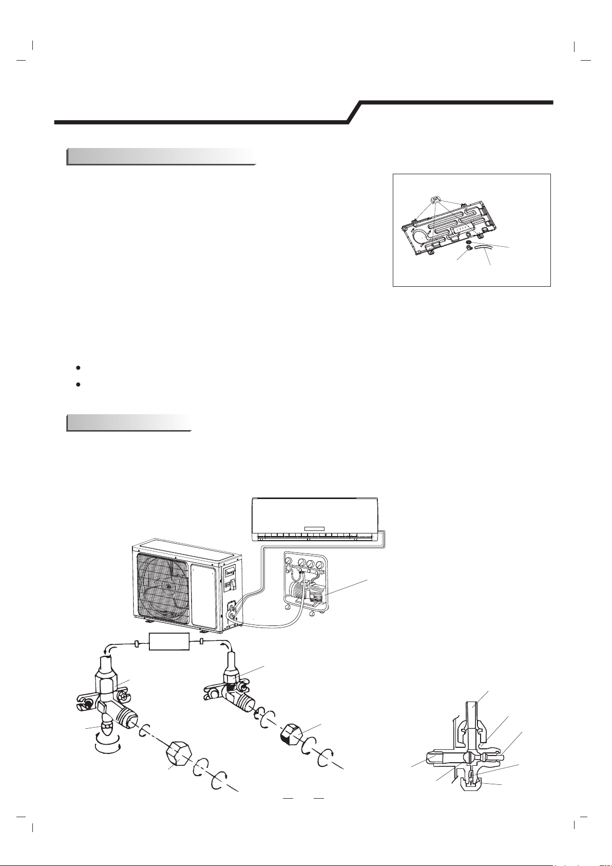
3. Outdoor Unit Piping Connection
4. Outdoor Unit Cable Connection (see previous page)
Remove the valve caps from the 2-way and 3-way valve.
Connect the pipes to the 2-way and 3-way valves separately according to the required torque.
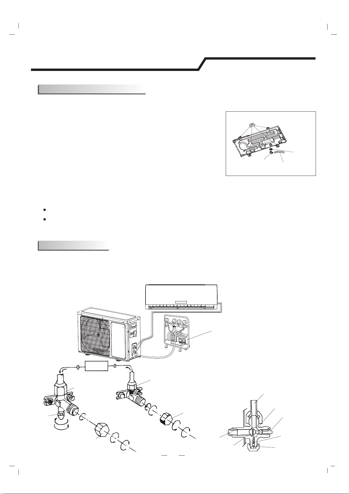
2. Install and Fix Outdoor Unit
1.Install Drain Port and Drain Hose (for heat-pump model only)
The condensate drains from the outdoor unit when the unit operates
in heating mode. In order not to disturb your neighbor and protect
the environment, install a drain port and a drain hose to direct the
condensate water. Just install the drain port and rubber washer to
the chassis of the outdoor unit, then connect a drain hose to the
port as the right figure shown.
The air which contains moisture remaining in the refrigeration cycle may cause a malfunction on the
compressor. After connecting the indoor and outdoor units, evacuate air and moisture from refrigerant
cycle using a vacuum pump, as shown below.
16
Installation instructions
Air purging
Note: To protect the environment, be sure not to discharge the refrigerant to the air directly.
See next page for air purging steps.
Outdoor unit installation
Refrigerant flow direction
2-way valve
(6) Open 1/4 turn
valve cap
(1) Turn
(8) Tighten
(2) Turn
3-way valve
(8) Tighten
(1) Turn
(7) Turn to fully open the
valve
(7) Turn to fully open the valve
(8) Tighten
3-way valve diagram
connect to indoor unit
open position
spindle
service port cap
Service
port
Connect to outdoor unit
Valve core
needle
Vacuum pump
indoor unit
Valve cap
Drain hose
(prepared by user)
Washer
Drain port
Rubber pad (optional)
Place under the leg pedestal
(1). Unscrew and remove caps from 2 and 3-way valves.
(4). Start vacuum pump for 10-15 minutes until reaching a vacuum of 10 mm Hg absolutes.
(6). Open 2-way valve 1/4 turn then close it after 10 seconds. Check tightness of all joints using liquid
soap or an electronic leak detector.
(7). Turn 2 and 3-way valves stem to fully the valves. Disconnect vacuum pump flexible hose.
(8). Replace and tighten all valve caps.
(5). With vacuum pump still running close the low pressure knob on vacuum pump manifold. Then stop
vacuum pump.
(2). Unscrew and remove cap from service valve.
(3). Connect vacuum pump flexible hose to the service valve.
How to Purge Air Tubes:
17
Installation instructions
!:
★
★★
★
" # $ % !
!!"
"
&'
(#℃)
*)&
+#℃,,(#℃)
&
(#℃)
-
$.℃)
/
/
$
&
"00)
1
.!2"!23
4
!
/
/
/
-
'
/
"5)!+
)0)'*
)'*
')5
61 *75))
!:★
★★
★
" # $ # $
!
!"
8 8 8
9
/
/
## 8 8
★
/
/
#$ 8
★
8
/
/
#3
★ ★ ★
*1:
1:/
#. 8
★ ★
*
7!).!)"!)
34
!
/
/
/
$
★ ★
8
★
*
'
$" 8
★
1'
7!).!;5℃
"!;57℃
*)&
,5℃<57℃=1
&
*
5<57℃=)
/
/
$#
★
8 1'
*)&
+#℃,,(#℃)
&
(#℃)
-
$.℃)
/
/
!'+
8!'+
1:5!
16
3
2
4
4
5
10
11
16
9
Introducción de Seguridad
Preparación antes del uso
Precauciones de seguridad
Identificación de piezas
Unidad interna
Unidad externa
introducción de visualización
Mantenimiento
Protección
Solución de problemas
Instrucciones de instalación
Diagrama de instalación
Selección de ubicación de instalación
Instalación de unidad interna
Instalación de unidad externa
Purga de aire
16
6
7
8
Tabla de Contenido
1
Instrucción de operación del control remoto. Véase “Instrucciones de Control Remoto”.
4
1
Introduccións de Seguridad
Para asegurar que la unidad funcione normalmente, por favor lea el manual
cuidadosamente antes de la instalación, e intente instalar estrictamente según este
manual.
No deje que la humedad del aire entre en el sistema de refrigeración ni descargue el
refrigerante al mover el acondicionador de aire.
Conecte el acondicionador de aire a tierra de manera adecuada.
Verifique los cables y tuberías de conexión cuidadosamente, asegúrese de que ellos
estén correctos y sólidos antes de conectar con la fuente de alimentación del
acondicionador de aire.
Deberá existir un interruptor de energía para el equipo acondicionador de aire.
Después de la instalación, el consumidor deberá operar el acondicionador de aire
correctamente de acuerdo con este manual, mantenga un almacenamiento adecuado
para el mantenimiento y movimiento del acondicionador de aire en el futuro.
Tipo de fusible utilizado en el controlador de unidad interna es Φ5mm X 20mm, de T
3,15A 250VAC.
Se aconseja que las instrucciones de instalación para los electrodomésticos destinados a
estar conectados permanentemente a un cableado fijo y que tengan una corriente de
fuga que supere los 10 mA, especifiquen que la instalación de un dispositivo diferencial
residual (DDR) tenga una corriente residual de operación no superior a 30 mA.
Advertencia: El riesgo de descarga eléctrica puede causar lesión o muerte. Desconecte
todas las fuentes de alimentación eléctricas remotas antes del mantenimiento.
La longitud máxima de la tubería de conexión entre la unidad interna y la unidad externa
deberá ser menos de 5 metros. Esa puede afectar la eficiencia del acondicionador de aire
si la distancia es mayor de dicha longitud.
El aparato puede ser utilizado por los niños desde los 8 años de edad y las personas con
capacidades reducidas físicas, sensoriales o mentales o falta de experiencia y
conocimientos si ellos son supervisado o se le ha dado instrucción sobre el uso del
aparato en una manera segura y con el entendimiento de los peligros involucrados. Los
niños no deberán jugar con el aparato. La limpieza y el mantenimiento por usuario no
deberán ser ejecutados por los niños sin supervisión.
Las baterías en el control remoto tienen que ser recicladas o desechadas de manera
adecuada. La eliminación de baterías agotadas – Por favor deseche las baterías como
basura municipal clasificada en el punto de colección accesible.
Si el aparato está de cableado fijo, el aparato tiene que estar equipado con medios de
desconexión desde la fuente de alimentación que tiene una separación de contacto en
todos los polos que proporciona la desconexión completa bajo las condiciones de
sobrevoltaje Categoría III, y estos medios tienen que ser incorporados en el cableado fijo
de acuerdo con las reglas de cableado.
Si el cable de alimentación está dañado, debe ser reemplazado por el fabricante, su
agente de servicio o las personas similarmente cualificados con el fin de evitar un peligro.
El aparato deberá instalarse de acuerdo con las regulaciones nacionales de cableado.
El acondicionador de aire deberá ser instalado por las personas profesionales o
cualificados.
El aparato no deberá instalarse en la lavandería.
2
Preparación antes del uso
Mantenga pulsado el botón de emergencia (ON/OFF) durante varios segundos, esta función será activada
si oye dos veces el pitido. Si sólo oye un pitido, esta función será cancelada.
Esta marcha indica que este producto no debe ser desechado junto con otras basuras
domésticas en toda la Unión Europea. Para evitar el daño posible al medio ambiente o la salud
humana desde el desecho de basuras no controlado, recíclelo responsablemente para promover
la reutilización sostenible de los recursos de materiales. Para devolver su dispositivo utilizado,
por favor utilice los sistemas de devolución y recolección o póngase en contacto con el vendedor
donde compró su producto. Ellos pueden tomar este producto para el reciclaje de protección
ambiental.
Protección del medio ambiente
Nota
Al cargar el refrigerante en el sistema, asegúrese de cargarlo en estado líquido, si el refrigerante del aparato
es R22 o R410A. De lo contrario, la composición química del refrigerante (R22 o R410A) dentro del sistema
puede cambiar y como una consecuencia, el rendimiento del acondicionador de aire será afectado.
Según la características del refrigerante (R410A), la presión del tubo es muy alta, por eso asegúrese de tener
cuidado cuando instala y repara el aparato.
Si el cable de alimentación está dañado, deberá ser reparado por el fabricante, su agente de servicio o las
personas similarmente cualificadas con el fin de evitar un peligro.
El acondicionador de aire deberán ser instalado por un ingeniero profesional.
La temperatura del circuito de refrigerante será alta, por favor mantenga el cable de
interconexión apartado del tubo de cobre.
Antes de utilizar el acondicionador de aire, asegúrese de verificar y preajustar de siguiente manera.
Preajuste del Control Remoto
Cada vez después de que al control remoto le sean reemplazadas las baterías o esté encendido, el control
remoto preajusta automáticamente la bomba de calor. Si el acondicionador de aire que compró es de modelo
de solo enfriamiento, el control remoto de bomba de calor sólo puede ser utilizado.
Función de contraluz (opcional)
Mantenga pulsado cualquier botón del control remoto durante alrededor de 2 segundos, la contraluz se
encenderá. Se apagará automáticamente después de unos 10 segundos.
Nota: La contraluz es una función opcional.
Preajuste de Reinicio Automático
El acondicionador de aire tiene la función de Reinicio Automático.
Puede ajustar o cancelar esta función cuando el acondicionador de aire está funcionando.
Este aparato es hecho de material reciclable o reutilizable. Su eliminación debe ser llevada a cabo de conformidad
con las regulaciones locales de eliminación de basuras. Antes de eliminarlo, asegúrese de cortar el cable de
alimentación para que el aparato no pueda ser reutilizado.
Para más información detallada en el manejo y reciclaje de este producto, póngase en contacto con sus
autoridades locales que gestionan la recolección separada de basuras o la tienda donde compró el aparato.
ELIMINACIÖN DEL APARATO
Este aparato es marcado de acuerdo con la Directiva Europea 2012/19/EC, Residuos de Equipo Eléctrico y
Electrónico (WEEE).
Los símbolos en este Manual de Uso y Cuidado se interpretan a continuación.
Preste la atención a dicha situación.
Asegúrese de no hacerlo.
Puesta a tierra es esencial.
Advertencia: El manejo incorrecto
puede causar un peligro grave tal
como muerte, lesión grave, etc.
3
No utilice el interruptor automático de
fuente de alimentación no tire el
enchufe macho para apagarlo durante
la operación. Eso puede causar un
incendio debido a las chispas, etc.
Mantenga el interruptor automático de
la fuente de alimentación o su enchufe
a apartado de la suciedad. Conecte el
cable de alimentación al cual sólida y
correctamente para que no se
produzca una descarga eléctrica o
incendio debido al contacto insuficiente.
Utilice la fuente de alimentación
correcta de conformidad con los
requisitos de la placa de identificación.
De lo contrario, los fallos o peligros
graves pueden ocurrir o se puede
producir un incendio.
No teja, tire o presione el cable de
alimentación, de lo contrario el cable
de alimentación puede dañarse. Una
descarga eléctrica o un incendio
pueden ser probablemente causados
por un cable de alimentación dañado.
Nunca inserte objetos o algún
obstáculo similar a la unidad. Como
el ventilador gira a alta velocidad,
este puede causar una lesión.
No repare el aparato por sí mismo.
Si esto se hace incorrectamente,
puede provocar una descarga
eléctrica, etcétera
Apague el aparato por el control
remoto primero antes de cortar la
fuente de alimentación si se
ocurre mal funcionamiento.
Es perjudicial para la salud si el
aire frío le da por mucho tiempo.
Es aconsejable dejar que el flujo
de aire sea desviado a toda la
habitación.
Evitar que el flujo de aire llegue a
los quemadores de gas y la estufa.
No toque el panel de control con
las manos mojadas.
No coloque ningún texto sobre la unidad
exterior
Es la responsabilidad del usuario
conectar el aparato a tierra de acuerdo
con los códigos u ordenanzas locales
por un técnico licenciado.
OFF
OFF
ON
ON
ON
OFF
MODE
SMART
QUIET
DIMMER
ECONOM Y
FEEL
FAN SPEED
CLOCK
TIMER ON
TIMER OFF
SLEEP
TEMP.
TEMP.
SUPER
Precauciones de seguridad
Las figuras en este manual se basan en la vista externa del modelo estándar.
Como una consecuencia, la forma puede diferir de la del acondicionador de aire que ha seleccionado.
Entrada de aire
Salida de aire
Persiana de
ajuste vertical
Persiana de ajuste
horizontal
Filtro de aire
Control remoto
Cable de conexión de tuberías
y alimentación Drain Hose
Panel de emergencia
Panel visualización
4
Unidad interna
Unidad externa
Entrada de aire
Panel frontal
O
N
O
F
F
MODE
SMART
QUIET
DIMME R
ECONO MY
FEEL
SUPER
FAN SPEED
CLOCK
TIMER O N
TIMER O FF
SLEEP
TEMP.
TEMP.
Identificación de piezas
Salida de aire
Manguera de drenaje
Nota: Agua condensada se drena en
operación de ENFRIAMIENTO O SECO.
5
Introducción de visualización
Los símbolos pueden ser diferentes de los modelos, pero las funciones son similares.
1 2 3 4 5 9
Serie VG/VL
Timer
Comp.
Run
Sleep
2
3
4
5
1
9
6
7
8
Indicador de temperatura
Visualización de temperatura ajustada
Muestra FC después de 200 horas de uso como un aviso de la limpieza del filtro. Después
de la limpieza del filtro, pulse el botón de restablecimiento del filtro ubicado en la unidad
interna por debajo del panel frontal con el fin de restablecer la pantalla. (opcional)
Indicador de operación
Se enciende cuando AC está funcionando.
Parpadea durante la descongelación.
Indicador de temporizador
Se enciende durante el ajuste del tiempo.
Indicador de sueño
Se enciende en el modo de sueño.
Indicador de compresor
Se enciende cuando el compresor está encendido.
Indicador súper
Se enciende en modo súper.
Indicador de modo
Se muestra naranja para calentador, se muestra
blanco para otros
Indicador de velocidad de ventilador
Receptor de señal
Indicador WIFI inteligente
Se ilumina cuando el WIFI está encendido.
10
Los símbolos pueden ser diferentes de los modelos, pero las funciones son similares.
5
1
2
3
4
5
9
Serie VT
Serie SE
1 23 45
9
Serie SF/DG (Lado derecho)
1 2 3 4 5
9
Introducción de visualización
Los símbolos pueden ser diferentes de los modelos, pero las funciones son similares.
5
Serie NT
Serie VQ/TE/TF/DA/DG (centro)/D
2
3
4
1 23 45
4
3
2
9
2
3
4
5
1
Serie NS/DE
9
9
Introducción de visualización
H
Los símbolos pueden ser diferentes de los modelos, pero las funciones son similares.
5
Serie VM
9
22
3
4
4
1
5
Serie NM/DF Serie NK
2
3
5
4
1
9
6
4
2
3
9
Introducción de visualización
1
10
4
3
Serie TA/TC
Serie TQ/TR
2
3
9
1 9
opcional
Los símbolos pueden ser diferentes de los modelos, pero las funciones son similares.
5
Serie VC
1
2
3
4
5
Timer
Comp.
Run
Sleep
9
Introducción de visualización
Serie SA/TD/TG/DB/DC/DJ/DK Serie SC
7
8
1
11
Botón de emergencia
11
ON/OFF para que AC funcione o pare con pulsar el botón.
9
1
2
3
4
6
Es necesario limpiar el filtro de aire
después de utilizarlo durante
alrededor de 100 horas.
Mantenimiento del panel frontal
Mantenimiento del filtro de aire
Nunca utilice las sustancias
volátiles tales como
gasolina o polvo de pulido
para limpiar el
aparato.
Limpie y reinstale el filtro de aire.
Cierre el panel frontal nuevamente
Limpie con un
paño suave y
seco.
Utilice el paño suave y
húmedo para limpiar si
el panel frontal está muy
sucio.
Nunca rocíe agua de manera
directa en la
unidad
interna.
Reinstale y cierre el panel
frontal.
Presione en los puntos "b" para fijar el panel
frontal
Si la suciedad es visible,
lávela con una solución de
detergente en el agua tibia.
Después de la limpieza,
déjelo secar en la sombra.
Detenga el electrodoméstico,
corte la corriente y quite el
filtro de aire.
1
2
3
b
b
Corte la fuente de alimentación
Apague el aparato primero antes
de desconectarlo desde la fuente
de alimentación.
Desconecte la fuente de
alimentación
Sujete el panel en los
puntos "a" y tire hacia
arriba para extraer el
panel frontal
a
a
Mantenimiento
Utilice un paño
seco y suave
para limpiarlo.
¡Peligroso!
¡Descarga
eléctrica!
1.Abra el panel frontal.
2.Presione el asa del filtro suavemente
desde el frente
3.Sujete el asa y extraiga el filtro.
Limpie el filtro de aire cada dos semanas si
el acondicionador de aire funciona en un
entorno extremadamente polvoriento.

7
Condición de operación
El dispositivo protector puede dispararse y parar el aparato en los casos abajo mencionados.
La temperatura de aire externo es superior a 24ºC
La temperatura de aire externo es inferior a -7ºC
La temperatura ambiental es superior a 27ºC
*
Para los modelos de condición de clima tropical (T3), el punto de temperatura es 55ºC en lugar de 43ºC.
Se permite que la temperatura de algunos productos sea mayor a este rango. En la situación específica, por favor
consulte el fabricante. Si el acondicionador de aire funciona en modo ENFRIAMIENTO o Deshumidificacion con
la puerta o ventana abierta durante un largo tiempo cuando la humedad relativa es superior a 80%, el rocío
pueden gotear desde la salida.
Contaminación de ruido
Instale el acondicionador de aire en un lugar donde pueda soportar su peso con el fin de que funcione
de manera más silenciosa.
Instale la unidad externa en un lugar donde el aire de la descargado y el ruido de operación no molesten
sus vecinos.
No coloque ningún obstáculo delante de la salida de aire de la unidad externa para evitar el aumento del nivel
de ruido.
Características del protector
Si toda la operación ha sido detenida, pulse el botón ON/OFF otra vez para reiniciar, el temporizador deberá
ser ajustado otra vez si ha sido cancelado.
El dispositivo protector funcionará en los casos siguientes.
Para reiniciar la unidad inmediatamente después de la parada del funcionamiento o cambiar el modo durante el
funcionamiento, necesita esperar durante 3 minutos.
Conecte con la fuente de alimentación y encienda la unidad inmediatamente, se arrancará después de 20
segundos.
Descongelación
Características del modo de CALEFACCION
En la operación de CALENTAMIENTO, el aparato se descongelará (deshielo) automáticamente para elevar la
eficiencia. Este procedimiento generalmente dura 2-10 minutos. Durante la descongelación, los ventiladores dejan
de funcionar.
Después de terminar la descongelación, se regresa al modo de CALEFACCION automáticamente.
Nota: El calentamiento NO es disponible para los modelos de acondicionador de aire de solo enfriamiento.
1.
2.
Protección
CALEFAC
CION
La temperatura de aire externo es superior a 43ºC
La temperatura ambiental es inferior a 21ºC
La temperatura ambiental es inferior a 28ºC
ENFRIAMIE
NTO
SECO
Precalentamiento
En el principio de la operación de CALEFACCION, el ventilador de la unidad interna operara de 2-5 minutos después.
Problema
8
Solución de Problemas
Los casos siguientes no siempre indican un mal funcionamiento, por favor verifíquelo antes de
solicitar el servicio.
La unidad se conmuta desde el modo de
calentamiento a descongelación. El indicador se
apaga dentro de diez minutos y se regresa al modo
de calentamiento.
¿Si el filtro de aire está sucio?
¿Las entradas y salidas del acondicionador de aire
están bloqueadas?
¿Si la temperatura está adecuadamente ajustada?
Análisis
Si el protector se dispara o el fusible está fundido.
Si el enchufe no está adecuadamente conectado.
Por favor espere durante 3 minutos y reinicie, el
dispositivo protector puede evitar el funcionamiento
de la unidad.
Si las baterías en el control remoto se agotan.
Si se presenta la interferencia fuerte (desde la
descarga excesiva de electricidad estática,
anomalía del voltaje de la fuente de alimentación),
el funcionamiento será anormal. En este
momento, desconéctelo desde la fuente de
alimentación y vuelva a conectarlo después de 2
a 3 segundos.
Si cambia el modo durante la operación, se retrasará
por 3 minutos.
Este olor puede ser procedente de otra fuente tal
como un mueble, un cigarrillo, etc., que es aspirado
en la unidad y soplado hacia afuera junto con el aire.
Causando por el flujo del refrigerante en el
acondicionador de aire, no es un problema.
El sonido de descongelación en el modo de
calentamiento.
El sonido puede ser generado por la expansión
o la contracción del panel frontal debido al
cambio de la temperatura.
La niebla se aparee cuando el aire en la habitación
se hace muy frio debido a la descarga de aire desde
la unidad interna durante el modo de operación de
ENFRIAMIENTO O DESHUMIDIFICACION:
No funciona
No se enfría o
caliente el aire
que sale de la
unidad
Control ineficaz
No funciona
inmediatamente
Olor peculiar
Un sonido de
flujo de agua
Se oye el sonido
de agrietamiento
Niebla de rocío
desde la salida
El indicador de compresor (rojo) se mantiene
encendido, y el ventilador interno deja de funcionar.
No funciona
9
Distancia desde la
pared deberá ser
superior a 50mm
Distancia de entrada de aire
desde la pared deberá ser
superior a 250mm.
Distancia de entrada de aire
desde la pared deberá ser
superior a 250mm.
Superior a 250mm
Distancia desde el techo deberá
ser superior a 200mm
Distancia desde la pared deberá
ser superior a 50mm
Distancia desde el suelo deberá ser
superior a 2500mm.
Instrucciones de instalación
Diagrama de instalación
La instalación deberá ser ejecutada de acuerdo con
las normas nacionales de cableado por el personal
autorizado sólo.
La figura arriba mencionada sólo es una
simple presentación de la unidad, puede
que no coincida con la apariencia externa
de la unidad que compró.
Distancia de salida de aire desde
la pared deberá ser superior a
500mm

Unidad externa
Unidad externa
Unidad interna
Unidad interna
La longitud de la
tubería es 15
metros Max.
La longitud de la tubería
es 15 metros Max.
La altura deberá ser
menos de 5m
La altura deberá
ser menos de 5m
10
Instrucciones de instalación
Selección de ubicación de instalación
Ubicación para Instalación de Unidad Externa
Donde es de instalación conveniente y bien ventilado..
Evite instalarlo en el lugar donde puede existir fuga de gas inflamable.
Mantenga una distancia requerida apartada de la pared.
La distancia entre la unidad interna y la unidad externa deberá ser 5
metros y puede alcanzar un máximo de 15 metros con la carga de
refrigerante adicional.
Mantenga la unidad externa apartada de un lugar de suciedad
grasienta y salida de gas de vulcanización.
Evite instalarlo en el lado del camino donde hay un riesgo de agua
fangosa.
Una base fija donde no está sujeta al ruido de funcionamiento
elevado.
Donde no hay ningún bloqueo en la salida de aire.
Si la altura y la longitud de la tubería son fuera del alcance de la tabla, por favor consulte el fabricante.
Ubicación para Instalación de Unidad Interna
Donde no hay obstáculo cerca de la salida de aire y el aire puede ser
soplado fácilmente a toda el área de la habitación.
Donde la tubería y agujeros de pared pueden ser fácilmente
ubicados.
Mantenga el espacio requerido desde la unidad al techo y la pared de
acuerdo con el diagrama de instalación en la página anterior.
Donde el filtro de aire puede ser fácilmente retirado.
Mantenga la unidad y el control remoto 1m o más apartados del
televisor, radio, etc.
Para evitar los efectos de las luces fluorescentes, manténgalo lo más
lejos como sea posible.
No coloque ninguna cosa cerca de la entrada de aire para obstruir la
absorción de aire.
Donde es de resistencia suficiente para soportar el peso y no va a
elevar el ruido de operación y vibración.
Modelo
5K~18K
5
15
5
20
Longitud máxima permisible
de tubería en envío (m)
Límite de
longitud de
tubería (m)
Límite de
diferencia de
elevación H (m)
Cantidad requerida de
refrigerante adicional (g/m)
22K.24K
28K.30K.36K
5
15
5
30
5
15
5
40
Dirección de tubería
1
2
3
4
A través
Nota: Al instalar la tubería en las direcciones 1, 2, o
4, asierre la pieza descargada correspondiente desde
la base de la unidad interna.
Pieza
descargada
Asierre la pieza de
descarga a lo largo de la
bandeja
Coloque la tubería ( líquido y gas) y los cables a través del agujero de pared desde el exterior o colóquelos desde el
interior después de terminar la conexión de la tubería y los cables del interior con el fin de conectar con la unidad
externa.
Decida la pieza que removerá de la carcasa de acuerdo con la dirección de la tubería (como se muestra a
continuación)
3.
Instalación de Tubería de Unidad Interna
11
Instrucciones de instalación
Nota: La forma de su placa de montaje puede ser diferente de la arriba mencionada, pero el método de instalación es
similar. Nota: Como se muestra en la figura arriba, los seis agujeros coincidentes con el tornillo autorroscante en la
placa de montaje deben ser utilizados para fijar la placa de montaje, otros son preparados.
Interior
Exterior
Cubierta de agujero de pared (tubo
de polietileno duro preparado por
el usuario)
5mm
(inclinado hacia abajo)
Instale una cubierta a través del agujero de la pared para
mantener ordenada y limpia la pared.
Perfore un agujero en la pared. El agujero deberá
inclinar un poco hacia abajo hacia el exterior.
Decida la posición del agujero para la tubería de
acuerdo con la ubicación de la placa de montaje.
2.
Perforación de un Agujero para la Tubería
Instalación de la Placa de Montaje
Decida una ubicación de instalación para la placa de montaje de acuerdo con la ubicación de la unidad interna y
la dirección de la tubería.
Mantenga la placa de montaje horizontalmente nivelada con una regla horizontal o plomada.
Perfore los agujeros de profundidad de 32mm en la pared para fijar la placa.
Inserte las anclas de plástico en los agujeros, fije la placa de montaje con los tornillos roscantes.
Inspeccione si la placa de montaje está bien fija. Luego perfore un agujero para la tubería.
1.
Instalación de unidad interna
Después de conectar la tubería según lo especificado, instale la manguera de drenaje. Luego conecte los cables de
alimentación. Después de la conexión, envuelva la tubería, los cables y la manguera de drenaje juntos con los
materiales de aislamiento térmico.
Placa de montaje
Tornillo autorroscantes
Instrucciones de instalación
Aislamiento Térmico de tuercas de
Tubería
:
Envuelva las juntas de
tubería con los materiales de
aislamiento térmico y envuélvalo con la
cinta de vinilo.
Aislamiento Térmico de Tubería:
a.
Coloque la manguera de drenaje por debajo de la tubería.
b.
El material de aislamiento deberá espuma de polietileno
de espesor superior a 6mm.
Nota: La manguera de drenaje es preparada por el usuario.
La tubería de drenaje deberá apuntar hacia abajo para el flujo
de drenaje fácil. No deje la tubería de drenaje torcida, que sale o
agita, no sumerja la punta en el agua.
Si una manguera de drenaje está conectada con la tubería de
drenaje, asegúrese de su aislamiento térmico al pasar a
través de la unidad interna.
Cuando la tubería es dirigida a la derecha, la tubería, el cable
de alimentación y la tubería de drenaje deberán ser
térmicamente aislados y fijos en la espalda de la unidad con
un fijador de tubería.
Aislamiento térmico
Envuelto por la cinta de vinilo
Tubería
pequeña
Cable de
alimentación 1
(para bomba de
calor)
Cable de descongelación
(para bomba de calor)
Manguera de drenaje
(Preparada por el usuario)
B. Presione para enganchar el fijador de tubería en la base.
Base
Base
Fijador de tubería
Enganche aquí
Inserte aquí
drain
hose
drain
hose
large
pipe
large
pipe
small
pipe
small
pipe
12
Cable de alimentación
Tubería larga
Tubo de aislamiento
térmico
Base
Fijador de tubería
A.Inserte el fijador de tubería en la ranura.
*
La unidad de 18K*,24K*,36K* es mayor de la unidad de 18K,24K,36K.
Tamaño de tubería
Modelo
5,7,8,9,10,12,14,15,18,24K
12,14,15,18K
18K*,22,24K*,28,30,36K
18K*,22,24,28,30,36K
36K*
5,7,8,9,10K
15~20N·m
17mm
0.5mm
0.6mm
0.6mm
0.6mm
0.6mm
30~35N·m
22mm
50~55N·m
24mm
30~35N·m
22mm
60~65N·m
27mm
Par
1.0mm
70~75N·m
32mm
b.
Pre-apriételos con los dedos primero, luego utilice las llaves.
a.
Conecte las tuberías de unidad interna con dos llaves. Preste especial atención
al par permitido como se muestra abajo para evitar la deformación y el daño
de las tuberías, conectores, tuercas.
Conexión de tubería:
Anchura
de tuerca
Espesor mínimo
Lado de líquido (φ6mm o 1/4 pulgada)
Lado de líquido (φ9.53mm o 3/8 pulgada)
Lado de gas (φ9.53mm o 3/8 pulgada)
Lado de gas (φ12mm o 1/2 pulgada)
Lado de gas (φ16mm o 5/8 pulgada)
Lado de gas (φ19mm o 3/4 pulgada)
4.
Conexión del Cable
Unidad Interna
Unidad Externa
1). Retire la puerta de acceso desde la unidad con liberando el
tornillo. Conecte los cables con los terminales en el tablero de
control de manera individual según lo abajo mencionado.
2). Fije el cable de conexión de alimentación en el tablero de
control con la abrazadera de cable.
3). Reinstale la puerta de acceso a la posición original con el
tornillo.
4)Utilice un interruptor automático reconocido para el
modelo 24K o superior entre la fuente de alimentación y la
unidad.
Un dispositivo interruptor para la desconexión adecuada de
todas las líneas de alimentación deberá ser instalado.
Conecte el cable de conexión de alimentación a la unidad
interna mediante la conexión de los cables a los terminales
en el tablero de control de manera individual de acuerdo con
la conexión de unidad externa.
Chasis
Gabinete
Panel frontal
Especificaciones de Cable
Nota: Para algunos modelos, es necesario retirar el gabinete
para conectar con el terminal de unidad interna.
Terminal (interior)
Terminal de
puerta de
acceso (interior)
Unidad interna
Unidad externa
Instrucciones de instalación
Precaución:
1.
Nunca omita un circuito de alimentación individual especificado para el acondicionador de aire. Para el
método de cableado, refiérase al diagrama de circuito colocado en el interior de la puerta de acceso.
2.
Confirme que el espesor del cable es como lo especificado en las especificaciones de fuente de
alimentación
3.
Verifique los cables y asegúrese de que todos estén sólidamente apretados después de la conexión cable.
4.
Asegúrese de instalar un interruptor automático de fuga puesto a tierra en un área húmeda o mojada.
Las figuras en este manual se basan en la vista
externa de un modelo estándar. Como una
consecuencia, la forma puede diferir de la del
acondicionador de aire que ha seleccionado.
13
2
2
El cable puede ser diferente de lo arriba mencionado. Puede ser utilizado como la siguiente lista. Y puede ser más largo.
0-7A, utilice 0,75mm o 18AWG. 0-10A, utilice 1mm o 16AWG. 0-16A, utilice 1,5mm o 14AWG.
0-20A, utilice 2,5mm o 14AWG. 0-25A, utilice 2,5mm o 12AWG. 0-32A, utilice 4mm o 12AWG.
2
2
2
2
Capacida
(Btu/h)
Al interior
H07RN-F
Cable de conexión de alimentación
Cable de alimentación
Tipo Tipo Tipo
Fuente de
alimentación
principal
Área de sección
ransversal normal
Área de sección
ransversal normal
Área de sección
ransversal normal
Cable de conexión de alimentación1
2.5mm
2
X3
Al interior
Al exterior
1.5~2.5mm
2
X3
5K~13K
H05VV-F
1.0~1.5mm
2
X3
H05VV-F
H05RN-F
H05RN-F
H05RN-F
1.5-2.5mm
2
X3
0.75mm
2
X2
(Bomba de calor)
0.75mm
2
X2
(Bomba de calor)
0.75mm
2
X3
(Bomba de calor)
0.75mm
2
X2
Al exterior
(Bomba de calor)
H07RN-F
H05RN-F
H07RN-F
1.0mm
2
X3
1.5mm
2
X3
1.0mm
2
X3
1.0mm
2
X4
enfriamiento Sólo
Al interior
18K~30K
1.5-2.5mm
2
X3
H05VV-F
1.5-2.5mm
2
X4
H07RN-F
H07RN-F
2.5~4.0mm
2
X3
Al exterior
24K~36K
H05RN-F
H07RN-F
14K~24K
H05RN-F
0.75mm
2
X2
(Bomba de calor&Opcional)
(Bomba de calor&Opcional)
18K~30K
H07RN-F
1.5mm
2
X5
H05RN-F
0.75mm
2
X4
24K~36K
H05RN-F
H05RN-F
H07RN-F
1.0mm
2
X4
0.75mm
2
X4
H05RN-F
0.75mm
2
X2
Instrucciones de instalación
Unidad interna
Diagrama de cableado
Unidad externa
Unidad interna
Para estos modelos, la fuente de alimentación está conectada desde la unidad externa, con un
interruptor automático.
Unidad interna
Unidad externaUnidad externa
Terminal Terminal
Terminal
Terminal
Terminal Terminal
N
L
1L1L
3L3L
2L2L
N
N
L
L
Fuente de alimentación
Fuente de alimentación
N
L
1L
1L
N
L
N
L
14
Modelo de 5K~24K
Modelo de 18K~30K
Modelo de 18K~30K
Azul
Amarillo/Verde
Marrón
Gris
Marrón
Azul
Marrón
Gris
Marrón
Amarillo/Verde
Amarillo/Verde
Gris
Marrón
Amarillo/Verde
Marrón
Gris
Unidad interna
Unidad externa
Cable de conexión de alimentación
Cable de conexión de alimentación
Cable de conexión de alimentación
Cable de conexión de alimentación
Cable de conexión de alimentación
Cable de conexión de alimentación I
Cable de conexión de alimentación I
Cable de conexión de alimentación
Cable de conexión de alimentación I
Azul
Azul
Azul
Azul
Azul
Azul
Azul
Azul
Azul
Azul
Azul
Azul
Amarillo/Verde
Amarillo/Verde
Amarillo/Verde
Amarillo/Verde
Amarillo/Verde
Amarillo/Verde
Amarillo/Verde
Amarillo/Verde
Marrón
Marrón
Marrón
Marrón
Marrón
Marrón
Marrón
Marrón
Marrón
Marrón
Marrón
Marrón
NN
2L
NN
2L
1L
1L
1L
1L
3L3L
Terminal Terminal Terminal Terminal
Unidad interna
Unidad externa
Nero
negronegro
negro
negro
Nero
negro
negro
N
N
1L
1(L)
L
L
Terminal
Terminal
Unidad interna
Unidad externa
N
N
1L
1L
L
L
Terminal
Terminal
Nota: Para algunos modelos, los indicadores “1L 2L 3L” pueden ser ‘4 5 6’ u otros.
Y los alambres pueden ser de color diferente.
Advertencia:
Antes de obtener acceso a las terminales, se deben desconectar todos los circuitos de abastecimiento.
2L2L
3L
3L
Instrucciones de instalación
15
y el conector deberá colocarse dentro de la unidad.
Ionizador (El ionizador es una pieza opcional)
Después de la conexión, el ionizador funcionará automáticamente.
Alambre de ionizador (interior)
Cable de descongelación (interior)
Sensor (exterior)
Después de la conexión, el cable de descongelación deberá ser bien envuelto con una cinta de
envoltura y el conector deberá colocarse dentro de la unidad.
Alambre (interior)
Después de la conexión, el alambre deberá ser bien envuelto con una cinta de envoltura
Protección de Sobrecalentamiento o cable de protección de alta presión( es una pieza opcional)
Sensor (exterior)
Fuente de alimentación
Para estos modelos, la fuente de alimentación está conectada desde la unidad externa, con un interruptor automático.
Cable de descongelación (sólo para acondicionador de aire de bomba de calor, y es una pieza opcional)
Modelo de 24K~36K
Unidad interna
Terminal Terminal
Terminal
N
L
1L
1L
L
N
S
R
negro
Amarillo/Verde
Gris
Marrón
Amarillo/Verde
negro
Marrón
Gris
Azul
3L
Azul
Marrón
Marrón
2L2L
3L
N
T
Unidad externa
Cable de conexión de alimentación
Cable de conexión de alimentación I
Unidad externaUnidad interna
Terminal
N
L
1L1L
3L
Terminal
3L
2L2L
N
N
L
L
Terminal
Fuente de alimentación
negro
Amarillo/Verde
Gris
Marrón
Marrón
negro
Marrón
Marrón
Gris
Amarillo/Verde
Cable de conexión de alimentación
Cable de conexión de alimentación I
AzulAzul
Unidad interna
Unidad externa
Terminal Terminal
Terminal
Fuente de alimentación
N
L
1L
1L
N
L
N
L
Amarillo/Verde
Gris
Marrón
Amarillo/V
erde
Marrón
Gris
Cable de conexión de alimentación
negro
negro
Nota: Para algunos modelos, los indicadores “1L 2L 3L” pueden ser ‘4 5 6’ u otros.
Y los alambres pueden ser de color diferente.
Advertencia:
Antes de obtener acceso a las terminales, se deben desconectar todos los circuitos de abastecimiento.
Fije con los pernos y tuercas firmemente en un suelo plano y fuerte.
Si está instalado en la pared o el techo, asegúrese de fijar el soporte bien
para evitar que agitación debido a la vibración grave o el viento fuerte.
3. Conexión de Tubería de Unidad Externa
4. Conexión de Cable de Unidad Externa (véase la página anterior)
Retire las tapas de válvula desde la válvula de 2 vías y 3 vías.
Conecte las tuberías a las válvulas de 2 vías y 3 vías de manera separada de acuerdo con el par especificado.
2.
1.Instalación del Puerto de Drenaje y Manguera de Drenaje (sólo para el modelo de bomba de calor)
Manguera de drenaje
(preparada por el usuario)
Arandela
Puerto de drenaje
El aire que queda en el circuito de refrigeración contiene humedad misma que puede causar un mal funcionamiento
en el compresor. Después de conectar las unidades interna y externa, evacúe el aire y la humedad desde el ciclo de
refrigerante con una bomba de vacío, como se muestra a continuación.
Instrucciones de instalación
Purga de aire
Nota: Para proteger el medio ambiente, asegúrese de no descargar el refrigerante al aire directamente. Véase la siguiente página
para los pasos de purga de aire.
Instalación de unidad externa
Válvula de 2 vías
valve cap
(8) Apriete
(2) Turn
Dirección de flujo de refrigerante
Válvula de 3 vías
(8) Apriete
(1) Turn
(7) Gire para abrir
completamente la válvula
(7) Gire para abrir completamente la válvula
(8) Apriete
Diagrama de válvula de 3 vías
Conecte con la unidad interna
Posición de apertura
Husillo
Tapa de puerto de
servicio
Núcleo de válvula
Aguja
Bomba de vacío
Tapa de válvula
Unidad interna
Almohadilla de goma (opcional) y
colocarlo bajo el pedestal inferior
El agua condensada es drenada desde la unidad eterna cuando la unidad
funciona en modo de calefacción. Con el fin de no molestar sus vecinos y
proteger el medio ambiente, instale un puerto de drenaje y una manguera
de drenaje para dirigir el agua condensada. Simplemente instale el puerto
de drenaje y la arandela de caucho en el chasis de la unidad externa, luego
conecte una manguera de drenaje al puerto como se muestra en la figura
derecha.
Instalación y Fijación de Unidad Externa
Puerto de
servicio
(6) Abra por 1/4 de una vuelta
(1) Turn
Conecte con
la unidad
externa
16

(1). Desatornille y retire las tapas desde las válvulas de 2 vías y 3 vías.
(2). Desatornille y retire la tapa desde la válvula de servicio.
(3). Conecte la manguera flexible de la bomba de vacío a la válvula de servicio.
(4). Encienda la bomba de vacío durante 10-15 minutos hasta que alcance un grado de presión absoluta de 10mmHg.
(6). Abra la válvula de 2 vías por 1/4 de una vuelta, luego ciérrela después de 10 segundos. Verifique la estrechez
de todas las juntas con el jabón líquido o un detector electrónico de fuga.
(7). Gire el vástago de válvulas de 2 vías y 3 vías para cerrar completamente las válvulas. Desconecte la manguera
flexible de la bomba de vacío.
(8). Coloque y apriete todas las tapas de válvula.
(5). Con la bomba de vacío en funcionamiento, cierre la perilla de baja presión en el múltiple de la bomba de vacío.
Luego apague la bomba de vacío.
Cómo evacuar los Tubos de Aire:
17
Instrucciones de instalación
Poder
Temporiz
ador
Funcionando Dormir
Observación
:★
★★
★
Encendida o Intermitente x Apagada
℃
℃ ! ℃
"
℃
#$
%
&'℃
(
&(
&
&))
*
'+,+,-
.
/%
(
"
(
&(
&
/
0
12
3"0
12
&0(
&
0
1&
3 1 (
)
* &
*&42&
44
56!/7
Poder
Temporizad
or
Funcio
nando
Dormir
Observación
:★
★★
★
Encendida o Intermitente x Apagada
" " "
8
"
9
"
(
"
&(
&
" "
★
8
4
(
&(
&
"
★
"
8
(
&(
&
-
★ ★ ★
8:;6<
4:;6<(
&
' "
★ ★
<
&
=+'++
-.
/%
(
"
(
&
(
&
★ ★
"
★
:
&"
&
"
★
:
&
=+'+>?℃
+>?=℃
5
%
0 ! ?℃
@?=℃A"2
2%?@?=℃A
(
&(
&
★
"
:
5
%
℃ ! ℃
"
℃
#$%
&'℃
(
&
&
!
!
"#$%&!
'!