Loading ...
Loading ...
Loading ...
– 2
Illustration on the inside of the front
cover
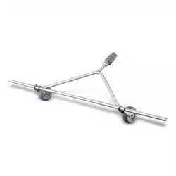
1 Screw connections
2 Star handle screw
3 Holder for spray bar
4 Chassis and suspension (WR 50)
5 Spray bars
6 Nozzles spray bars
7 Temperature indicator
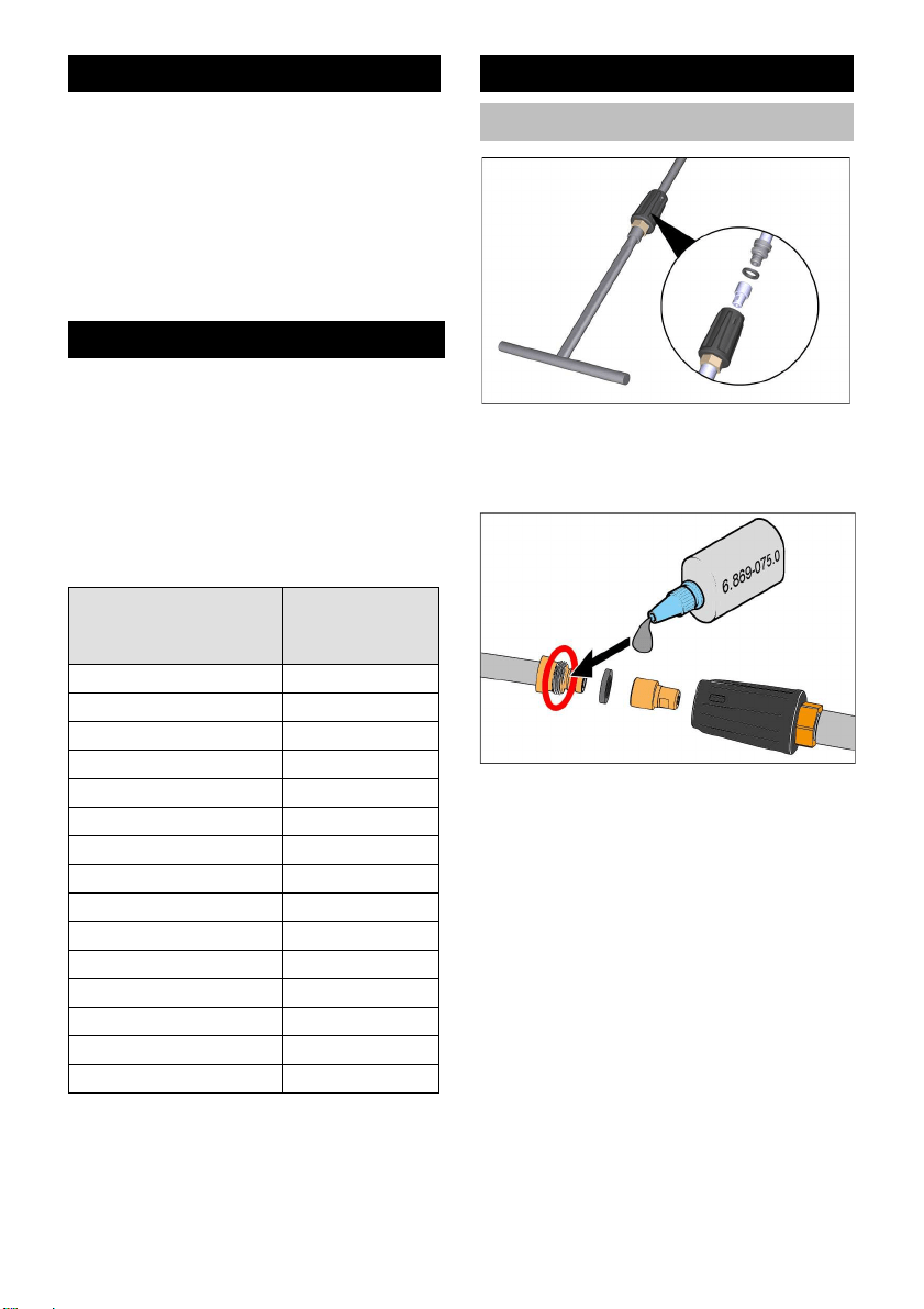
In order to maintain a consistently high tem-
perature (above 90°C) of the water, a pow-
er nozzle must be inserted into the screw
connection of the spray bar to restrict the
flow.
Note
The necessary power nozzle is matched to
the corresponding high-pressure cleaner
and must be ordered separately.
Note: Power nozzles for hot water high-
pressure cleaners not listed here must be
requested from the service partner.
Push power nozzle into the screw con-
nection.
Insert the sealing ring between the pow-
er nozzle and the spray lance.
Apply metal glue 6.867-075.0 (provid-
ed) to the thread of the spray lance.
Screw the spray bars onto the spray
lance.
Note
Observe drying time of the metal glue!
Note
The connection can no longer be loosened
after the metal glue has hardened.
Device elements
Flow restrictor
Hot water high-pres-
sure cleaner
Order
number Power
nozzle
HDS 6/14 C 2.113-070.0
HDS 6/14-4 C 2.113-070.0
HDS 7/12-4 M 2.113-006.0
HDS 7/16 C 2.113-041.0
HDS 8/17 C 2.113-071.0
HDS 8/18-4 C 2.113-071.0
HDS 8/18-4 M 2.113-071.0
HDS 9/18-4 M 2.113-005.0
HDS 10/20-4 M 2.113-021.0
HDS 12/18-4 S 2.113-010.0
HDS 13/20-4 S 2.113-025.0
HDS 1000 De 2.113-071.0
HDS 1000 Be 2.113-071.0
HDS 13/20 DeTr.1 2.113-026.0
HDS 17/20 DeTr.1 2.113-026.0
Spray bar
Installing the spray bar
8 EN
Loading ...
Loading ...
Loading ...