
SWA/RS
MODEL NUMBER 917.256611
®Assembly
oOperation
Customer Responsibilities
®Service and Adjustments
Repair Parts
l/
OWNER'S MANUAL
®
L;AUTION: Read and follow all safety rules and instructions before operating this equipment.
FOR CONSUMER ASSISTANCE HOT LINE, CALL THIS TOLL FREE NUMBER: 1-800-659-5917
SAFETY RULES
Safe Operation Practices for Ride-On Mowers
iMPORTANT: THIS CUTTING MACHINE iS CAPABLE OF AMPUTATING HANDS AND FEET AND THROWING OBJECTS
FAILURE TO OBSERVE THE FOLLOWING SAFETY INSTRUCTIONS COULD RESULT iN SERIOUS INJURY OR DEATH
GENERAL OPERATION
Read, understand, and follow all instructions in the manual
and on the machine before starting.
Only allow responsible adults, who are familiar with the
instructions, to operate the machine.
Clear the area of objects such as rocks, toys, wire, etc.,
which could be picked up and thrown by the blade.
Besure the area is clear of other people before mowing. Stop
machine if anyone enters the area.
Never carry passengers.
Do not mow in reverse unless absolutely necessary. Always
look down and behind before and while backing.
Be aware of the mower discharge direction and do not point
it at anyone. Do not operate the mower without either the
entire grass catcher or the guard in place.
Slow down before turning.
Never leave a running machine unattended. Always turn off
blades, set parking brake, stop engine, and remove keys
before dismounting.
Turn off blades when not mowing.
Stop engine before removing grass catcher or unclogging
chute.
Mow only in daylight or good artificial light.
Do not operate the machine while under the influence of
alcohol or drugs.
Watch for traffic when operating near or crossing roadways,
Use extra care when loading or unloading the machine into
a trailer or truck,
II. SLOPE OPERATION
Slopes are a major factor related to loss-of-control and
tipover accidents, which can result insevere injury or death.
All slopes require extra caution. If you cannot back up the
slope or if you fee! uneasy on it, do not mow it.
DO:
o Mow up and down slopes, not across.
Remove obstacles such as rocks, tree limbs, etc.
Watch for holes, ruts, or bumps. Uneven terrain could
overturn the machine. Tall grass can hide obstacles,
Use slow speed. Choose alow gear so that you will not have
to stop or shift while on the slope.
Follow the manufacturer's recommendations for wheel
weights or counterweights to improve stability.
• Use extra care with grass catchers or other attachments.
These can change the stability of the machine.
Keep all movement on the slopes slowand gradual Do not
make sudden changes in speed or direction.
Avoid starting or stopping on a slope. If tires lose traction,
disengage the blades and proceed slowly straight down the
slope.
DO NOT:
Do not turn on slopes unless necessary, andthen, turn slowly
and gradually downhill, if possible.
Do not mow near drop-offs, ditches, or embankments. The
mower could suddenly turn over if a wheel is over the edge
of a cliff or ditch, or if an edge caves in.
Do not mow on wet grass, Reduced traction could cause
sliding.
Do not try to stabilize the machine by putting your foot on the
ground.
Do not use grass catcher on steep slopes.
III. CHILDREN
Tragic accidents can occur if the operator is not alert to th_
presence of children. Children are often attracted to th_
machine and the mowing activity. Never assume tha
children will remain where you last saw them.
Keep children out of the mowing area and under the watchfu
care of another responsible adult.
Be alert and turn machine off if children enter the area.
Before and when backing, look behind and down for smal
children.
Never carry children. They may fall off and be seriousl_
injured or interfere with safe machine operation.
Never allow children to operate the machine.
Use extra care when approaching blind corners, shrubs
trees, or other objects that may obscure vision.
IV. SERVICE
Use extra care inhandling gasoline and other fuels. They are
flammable and vapors are explosive.
Use only an approved container.
Never remove gas cap or add fuel with the engine
running. Allow engine to cool before refueling. Do no
smoke.
Never refuel the machine indoors.
Never store the machine or fuel container inside wher_
there is an open flame, such as a water heater,
Never run a machine inside a closed area.
Keep nuts and bolts, especially blade attachment bolts, tigh/
and keep equipment in good condition,
Never tamper with safety devices. Check their propel
operation regularly.
Keep machine free of grass, leaves, or other debris build-up,
Clean oil or fuel spillage. Allow machine to cool before
storing.
Stop and inspect the equipment if you strike an object.
Repair, if necessary, before restarting.
Never make adjustments or repairs with the engine running.
Grass catcher components are subject to wear, damage, and
deterioration, which could expose moving parts or allow
objects to be thrown. Frequently check components and
replace with manufacturer's recommended parts, when nec-
essary.
Mower blades are sharp and can cut. Wrap the blade(s) or
wear gloves, and use extra caution when servicing them.
Check brake operation frequently. Adjust and service as
required.
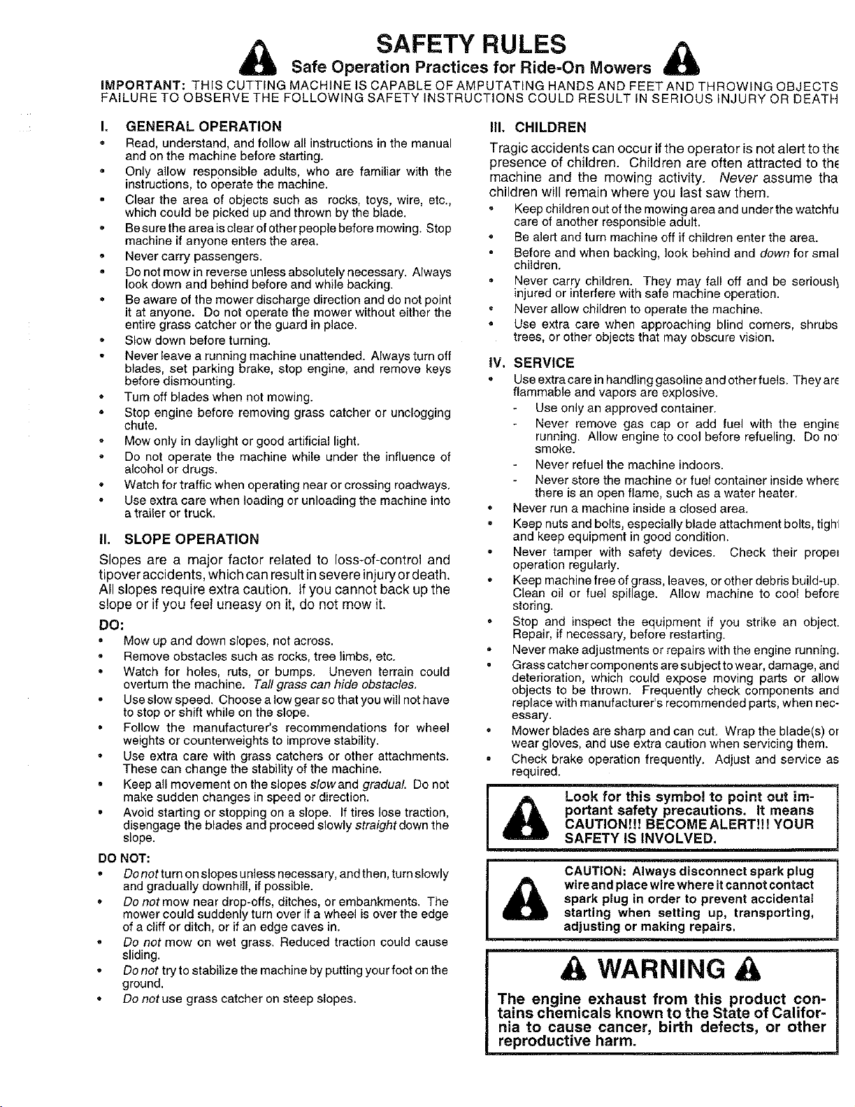
_lb ook for this symbol to point out im-
portant safety precautions. It means
CAUTION!H BECOMEALERT!H YOUR
SAFETY IS INVOLVED.
CAUTION: Always disconnect spark plug
_ wire and place wire where it cannot contact
spark plug in order to prevent accidental
starting when setting up, transporting,
adjusting or making repairs.
A WARNING
The engine exhaust from this product con-
tains chemicals known to the State of Califor-
nia to cause cancer, birth defects, or other
reproductive harm.

CONGRATULATIONS on your purchase of a Sears
tractor. It has been designed, engineered and manufac-
tured to give you the best possible dependability and
performance.
Shou d you experience any problem you cannot easily
remedy, please contact your nearest Sears Service Cen-
ter/Department. We have competent, well-trained tech-
nicians and the proper tools to service or repair this trac-
tor.
Please reao and retain this manual. The instructions will
enable you to assemble and maintain your tractor prop-
eny. Always observe the "SAFETY RULES".
MODEL
NUMBER 917.256611
SERIAL
NUMBER
DATE OF PURCHASE
THE MODEL AND SERIAL NUMBERS WILL BE FOUND
ON A PLATE UNDER THE SEAT.
YOU SHOULD RECORD BOTH SERIAL NUMBER AND
DATE OF PURCHASE AND KEEP IN A SAFE PLACE
FOR FUTURE REFERENCE.
MAINTENANCE AGREEMENT
A Sears maintenance agreement is available on this prod-
uct. Contact your nearest Sears store for details.
CUSTOMER RESPONSIBILITIES
Read and observe the safety rules.
Follow a regular schedule in maintaining, caring for and
using your tractor.
Follow the instructions under "Customer Responsibili-
ties" and "Storage" sections of this owner's manual.
PRODUCT SPECiFiCATiONS
HORSEPOWER: 15.5
GASOLINE CAPACITY 3.5 GALLONS
AND TYPE: UNLEADED REGULAR
OIL TYPE (API=SF/SG): SAE 10W-30 {above 32°F)
SAE 5W-30 (below 32°F)
OIL CAPACITY: W/FILTER: 4.0 PINTS
W/O FILTER: 3.5 PINTS
SPARK PLUG: CHAMPION RC12YC
GAP: .040"',
VALVE CLEARANCE: NOT ADJUSTABLE
GROUND SPEED (MPH): FORWARD: 5.5
REVERSE: 2.4
TIRE PRESSURE: FRONT: 14 PSI
REAR: 10 PSI
CHARGING SYSTEM: 3 AMPS BATTERY
5 AMPS HEADLIGHTS
BATTERY: AMP!HR: 30
MIN. CCA: 240
CASE SIZE: U1R
BLADE BOLT TORQUE: 30-35 FT. LBS.
WARNING: This tractor s equipped with an internal
combustion engine and should not be used on or near any
unimproved forest-covered brush-covered or grass-cov-
ered land unless the engine's exhaust system is equipped
with a spark arrester meeting applicable local or state laws
(if any). If a_spark arrester is used, it should be maintained
n effective working order by the operator,
n the state of California the above is required by law
(Section 4442 of the california Public Resources Code).
Other states may have similar laws. Federal laws apply on
federal lands. A spark arrester for the muffler is available
through your nearest Sears Authorized Service Center
(See REPAIR PARTS section of this manual).
LiMiTED TWO YEAR WARRANTY ON CRAFTSMAN RiDiNG EQUIPMENT
For two (2) years from the date of purchase, ifthis Craftsman Riding Equipment is maintained lubricated and tuned up according
to the instructions in the owner's manual. Sears will reeair or replace, free of charge, any parts found to be defective in material
or workmanship.
This Warranty does not cover:
Expendable items which become worn during normal use. such as blades, spark plugs, air cleaners, belts, etc.
Tire replacement or repair caused by punctures from outside objects, such as nails, thorns, stumps, or glass,
Repairs necessary because of operator abuse, negligence, improper storage or accident or the failure to maintain the
equipment according to the instructionscontained in the owner's manual
Riding equipment used for commercial or rental purposes.
LIMITED 90 DAY WARRANTY ON BATTERY
For ninety (90) days from date of purchase, if any battery included with this riding equipment proves defective in material or
workmanship and our testing determines the battery will not hold a charge, Sears will replace the battery at no charge.
IN-HOME WARRANTY SERVICE ON YOUR CRAFTSMAN RIDING EQUIPMENT IS AVAILABLE AT NO-CHARGE FOR 30
DAYS FROM THE DATE OF PURCHASE, PLEASE CONTACT YOUR NEAREST SERVICE CENTER. AFTER 30 DAYS
FROM THE DATE OF PURCHASE. WARRANTY SERVICE IS AVAILABLE BY TAKING YOUR CRAFTSMAN RIDING EQUIP-
MENT TO YOUR NEAREST SEARS SERVICE CENTER. (IN-HOME WARRANTY SERVICE WILL STILL BE AVAILABLE
AFTER 30 DAYS FROM THE DATE OF PURCHASE BUT A STANDARD TRIP CHARGE WILL APPLY.) THIS WARRANTY
APPLIES ONLY WHILE THIS PRODUCT IS IN THE UNITED STATES,
This Warranty gwes you specific legal rights, and you may also have other rights which may vary from state to state,
SEARS, ROEBUCK AND CO., D/817 WA, HOFFMAN ESTATES, IL 60179
3
TABLE OF CONTENTS
SAFETY RULES ............................................................ 2
PRODUCT SPECIFICATIONS ...................................... 3
CUSTOMER RESPONSIBlUTIES ..................... 3, 16-19
WARRANTY .................................................................. 3
TRACTOR ACCESSORIES .......................................... 5
ASSEMBLY ............................................................. 7-!0
OPERATION .......................................................... 11-16
MAINTENANCE SCHEDULE ..................................... 17
SERVICE AND ADJUSTMENTS ................ ........... 21-27
STORAGE ................................................................... 28
TROUBLESHOOTING ........................................... 29-30
REPAIR PARTS - TRACTOR ................................ 32-49
REPAIR PARTS - ENGINE .................................... 50-55
PARTS ORDERING/SERVICE ............... BACK COVER
iNDEX
A
Accessories ........................................... 5
Adjustments:
Brake ............................................ 24
Carburetor .................................... 27
Mower
Front-To-Back ......................... 22
Side-To-Side ........................... 22
Throttle Control Cable .................. 27
Air Filter. Engine .................................. 20
Air Screen. Engine .............................. 19
Assembly .......................................... 7-10
B
Battery:
Charging ...................................... 8
Cleaning ....................................... 18
Starting with Weak Battery .L....... 25
Storage ........................................ 28
Terminals ..................................... 18
Belt:
Motion Drive
Removal/Replacement ........... 24
Mower Belt(s)
Removal/Replacement ........... 23
Blade:
Sharpentng .................................. 18
Replacement ................................ 18
Brake Adjustment ................................ 24
C
Carburetor AdJustment ........................ 27
Controls. Tractor ................................. 12
Customer Responsibilities ............. 17-20
Engine:
Air Filter .................................... 20
Air Screen ................................ 19
Cooling Fins ............................. 20
Engine Oil ........................... 15,19
Fuel Filter ................................. 20
Spark Plug(s) ........................... 20
Tractor:
Battery ...................................... 18
Blade ........................................ 18
Lubrication Chart ..................... 17
Maintenance Schedule ............ 17
Tire Care .......................... 8,18,25
Transaxle ................................. 19
Cutting Height, Mower ........................ 13
E
Electrical:
nterlocks and Relays .................. 26
Schematic ................................... 31
Wiring Diagram ......................... 32
Engine:
Air Filter ........................................ 20
Air Screen .................................... 19
Cooling Fins ................................. 20
Oil Change ................................... 19
Oil Level ...................................... 19
Oil Type .................................. 15.19
Preparation .................................. 15
Repair Parts ............................ 50-55
Starting ........................................ 15
Storage ........................................ 28
F
Filter:
Air Filter ........................................ 20
Fuel .............................................. 20
Fuel:
Type ........................................... 15
Storage ........................................ 28
Fuse .................................................... 26
H
Hood Removal/Installation ..................26
L
Leveling Mower Deck .......................... 22
Lubrication:
Chart ............................................ 17
Engine .......................................... 19
M
Maintenance Schedule ....................... 17
Mower:
Adjustment. Front-to-Back ........... 22
Adjustment. Side-to-Side ............. 22
Blade Replacement ..................... 18
Blade Sharpening ........................ 18
Cutting Height .............................. 13
Installation ................................... 29
Operation ..................................... 14
Removal ....................................... 21
Mowing Tips ........................................ 16
Muffler ................................................ 20
Spark Arrester ........................... 3.40
Oil:
o
Cold Weather Conditions ........ 15,19
Engine .......................................... 19
Storage ....................................... 28
Oeeration ....................................... 12-16
Operating Mower ................................ 14
Options:
Accessories .................................... 5
Spark Arrester ........................... 3.40
P
Parking Brake ............................... 12-13
Parts Bag .............................................. 6
Parts. Replacement/Repair ............ 32-49
Product Specifications .......................... 3
R
Repair Parts ................................... 32-55
S
Safety Rules .......................................... 2
Seat ....................................................... 8
Service and Adjustments ............... 21-27
Carburetor .................................... 27
Fuse ............................................. 26
Hood Removal/Installation ........... 26
Motion Drive Belt
Removal/Replacement ........... 24
',Aower Belt(s)
Removal/Replacement .......... 23
Mower Adjustment
Front-to-Back .......................... 22
Side-to-Side ............................ 22
Mower Removal/Installation ......... 21
Tire Care .............................. 8,18,25
Slope Guide Sheet .............................. 59
Spark Plug(s.. ..................................... 20
Specifications ........................................ 3
Starting the Engine ............................. 15
Steering Wheel ................................ 7.25
Stopping the Tractor ........................... 13
Storage ............................................... 28
T
Throttle Control Cable Adjustment ...... 27
Tires ............................................ 8.18.25
Trouble Shooting Chart .................. 29-30
Transaxle .......................................... 19
W
Warranty ................................................ 3
Wiring Diagram ................................... 32
Wiring Schematic ................................ 31
4
ACCESSORIES AND ATTACHMENTS
These ascessodes and attachments were available through most Sears retail outlets and service centers when the tractor was purchased
Most Sears stores can order these items for you when you provide the model number of your tractor
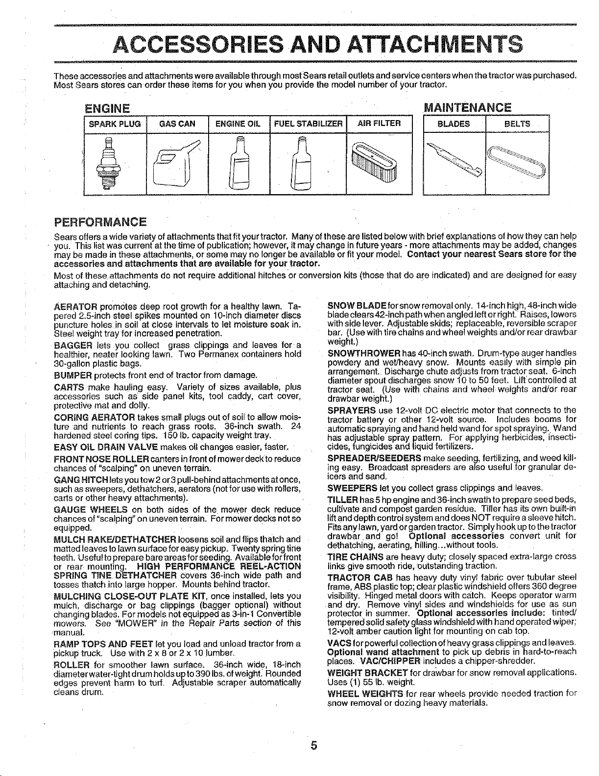
ENGINE
SPARK PLUG
MAINTENANCE
GAS CAN
ENGINEOIL
A
2
FUELSTABILIZER
A
I--
AiR FILTER
BLADES BELTS
PERFORMANCE
Sears offers awide variety of attachments that fit your tractor. Many of these are listed below with brief explanations of how they can help
you. This list was current at the time of publication; however, itmay change in future years - more attachments may be added, changes
may be made in these attachments, or some may no longer be available or fit your model. Contact your nearest Sears store for the
accessories and attachments that are available for your tractor,
Most of these attachments do not require additional hitches or conversion kits (those that do are indicated_ and are designed for easy
attaching and detaching,
AERATOR promotes deep root growth for a healthy lawn. Ta-
pered 2.5-inch steel spikes mounted on 10-inch diameter discs
PsUnCtureholes in soi! at close intervals to let moisture soak in.
reel weight tray for increased penetration.
BAGGER lets you collect grass clippings and leaves for a
healthier, nearer looking lawn. Two Permanex containers hold
30-gallon plastic bags.
BUMPER protects front end of tractor from damage,
CARTS make hauling easy. Variety of sizes available plus
accessories such as side panel kits tool caddy, cart cover.
protective mat and dolly.
CORING AERATOR takes sina!! plugs out of soil to allow mois-
ture and nutrients to reach grass roots. 36-inch swath. 24
hardened steel coring tips. 150 lb. capacity weight tray.
EASY OiL DRAIN VALVE makes oil changes easier, faster.
FRONT NOSE ROLLER canters in front of mower deck to reduce
chances of "scalping" on uneven terrain.
GANG HITCH lets you tow 2or 3 pull-behind attachments at once.
such as sweepers, dethatchers, aerators ('notfor use with rollers.
carts or other heavy attachments).
GAUGE WHEELS on both sides of the mower deck reduce
chances of "scalping" on uneven terrain. For mower decks not so
equipped.
MULCH RAKF_JDETHATCHER loosens soil and flips thatch and
matted leaves to lawn surface for easy pickup. Twenty spring tine
teeth. Useful to prepare bare areas for seeding. Available for front
or rear mounting. HiGH PERFORMANCE REEL-ACTION
SPRING TINE DETHATCHER covers 36-inch wide path and
tosses thatch into large hopper. Mounts behind tractor.
MULCHING CLOSE-OUT PLATE KIT, once installed, lets you
mulch discharge or bag clippings (bagger optional) without
changing blades. For models not equipped as 3oin-1 Convertible
mowers. See "MOWER" in the Repair Parts section of this
manual.
RAMP TOPS AND FEET let you load ane unload tractor from a
pickup truck, Use with 2 x 8 or 2 x 10 lumber.
ROLLER for smoother lawn surface. 36-inch wide. 18-inch
diameter water-tight drum holds up to 390 Ibs.ofweight. Rounded
edges prevent harm to turf Adjustable scraper automatically
cleans drum.
SNOW BLADE for snow removal only. 14-inch hign 48-inch wide
blade clears 42-inch pathwhen angled teft or right. Raises, lowers
with side lever. Adjustable skids; replaceable, reversible scraper
bar (Use with tire chains and wheel weights and/or rear drawbar
weight.)
SNOWTHROWER has 40-inch swath. Drum-type auger handles
powdery and wet/heavy snow. Mounts easily with simple pin
arrangement. Discharge chute adjusts from tractor seat. 6-inch
diameter spout discharges snow 10 to 50 feet. Lift controlled ai
tra_or seat. (Use with chains and wheel weights and/or rear
drawbar weight.)
SPRAYERS use 12-volt DC electric motor that connects to the
tractor battery or other 12-volt source, Includes booms for
automatic spraying and hand held wand for spot spraying. Wand
has adjustable spray pattern, For applying herbicides, insecti-
cides, fungicides and liquid fertilizers.
SPREADEPJSEEDERS make seeding, fertilizing, and weed kill-
ing easy. Broadcast spreaders are also useful for granular de-
icers and sand,
SWEEPERS let you collect grass clippings and leaves
TILLER has 5 hp engine and 36-inch swath to prepare seed beds.
cultivate and compost garden residue. Tiller has its own built-in
lift and depth control system and does NOT require a sleeve hitch.
Fits any lawn, yard or garden tractor. Simply hook up to the tractor
drawbar and go! Optiona! accessories convert unit for
dethatching, aerating, hilling...without tools.
TIRE CHAINS are heavy duty; closely spaced extra-large cross
links give smooth ride. outstanding traction.
TRACTOR CAB has heavy duty vinyl fabric over tubular steel
frame ABS plastic top; clear plastic windshield offers 360 degree
visibility. H nged metal doors with catch. Keeps operator warm
and dry. Remove wnyl sides and windshields for use as sun
protector in summer_ Optional accessories include: tinted/
tempered solid safety glass windshield with hand operated wiper;
12-voll amber caution light for mounting on cab top.
VACS for powerful collection ofheavy grass clippings and leaves.
Optional wand attachment to pick up debris in hard-to-reach
places, MAC/CHIPPER includas a ch_pper-shredder.
WEIGHT BRACKET for drawbar for snow removal applications,
Uses (1) 55 lb. weight.
WHEEL WEIGHTS for rear wheels provide needed traction for
snow removal or dozing heavy materials.
5
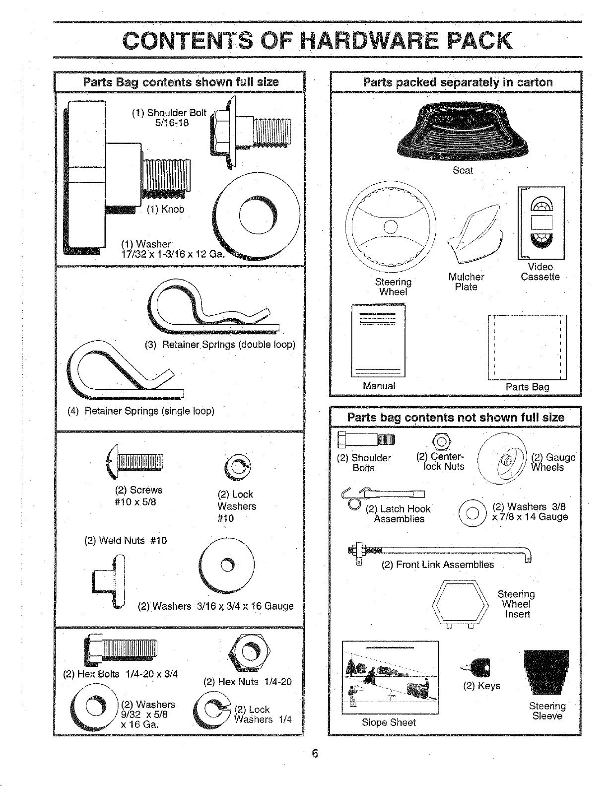
CONTENTS OF PAC
Parts Bag contents shown full size
(1) Shoulder Bolt
5/16-18
(1) Knob
(1) Washer
17/32 x
/
©
(3) Retainer Springs (double loop)
(4) Retainer Springs (single loop)
(2) Screws (2) Lock
#10 x 5/8 Washers
#10
(2) Weld Nuts #10 _
(2) Washers 3/16 x 3/4 x 16 Gauge
(2) Hex Bolts 1/4-20 x 3/4
\
) (2) Washers
_ /9/32 x5/8
_,/ x 16 Ga,
@
(2) Hex Nuts 1/4_20
(2) Lock
Washers 1/4
Parts packed separately in carton
Seat
Steering Mulcher
Wheel Plate
Video
Cassette
Manual Parts Bag
Parts bag contents not shown full size
(2_Center- ) (2) Gauge
Bolts lock Nuts / Wheels
_k
Assemblies
(2) Washers 3/8
x 7/8 x 14 Gauge
_(2) Front Link Assemblies
Steering
Wheel
Insert
Slope Sheet
(2) Keys
Steering
Sleeve
6
ASSEMBLY
Your new tractor has been assembled at the factory with exception of those parts left unassembled for,shipping purposes.
To ensure safe and proper operation of your tractor, all parts and hardware you assemble must be tightened securely. Use
the correct tools as necessary to insure proper tightness,
TOOLS REQUIRED FOR ASSEMBLY
A socket wrench set will make assembly ees_er. Standard
wrench sizes are listed.
(1) 3/4" wrench (2) 7/16" wrench
(1) 9/16" wrench Utility knife
(1) 1/2" wrench Tire pressure gauge
(1) 3/4" socket w/drive ratchet
When right and left hand is mentioned in this manual, it
means when you are in the operating position (seated
behind the steering wheel).
TO REMOVE TRACTOR FROM CARTON
UNPACK CARTON
Remove all accessible loose parts and parts cartons
from carton (See page 6).
Cut, from top to bottom, along lines on all four corners
of carton, and lay panels flat,
Remove mower and packing materials.
Check for any additional oose parts or cartons and
remove.
BEFORE ROLLING TRACTOR OFF
SKiD
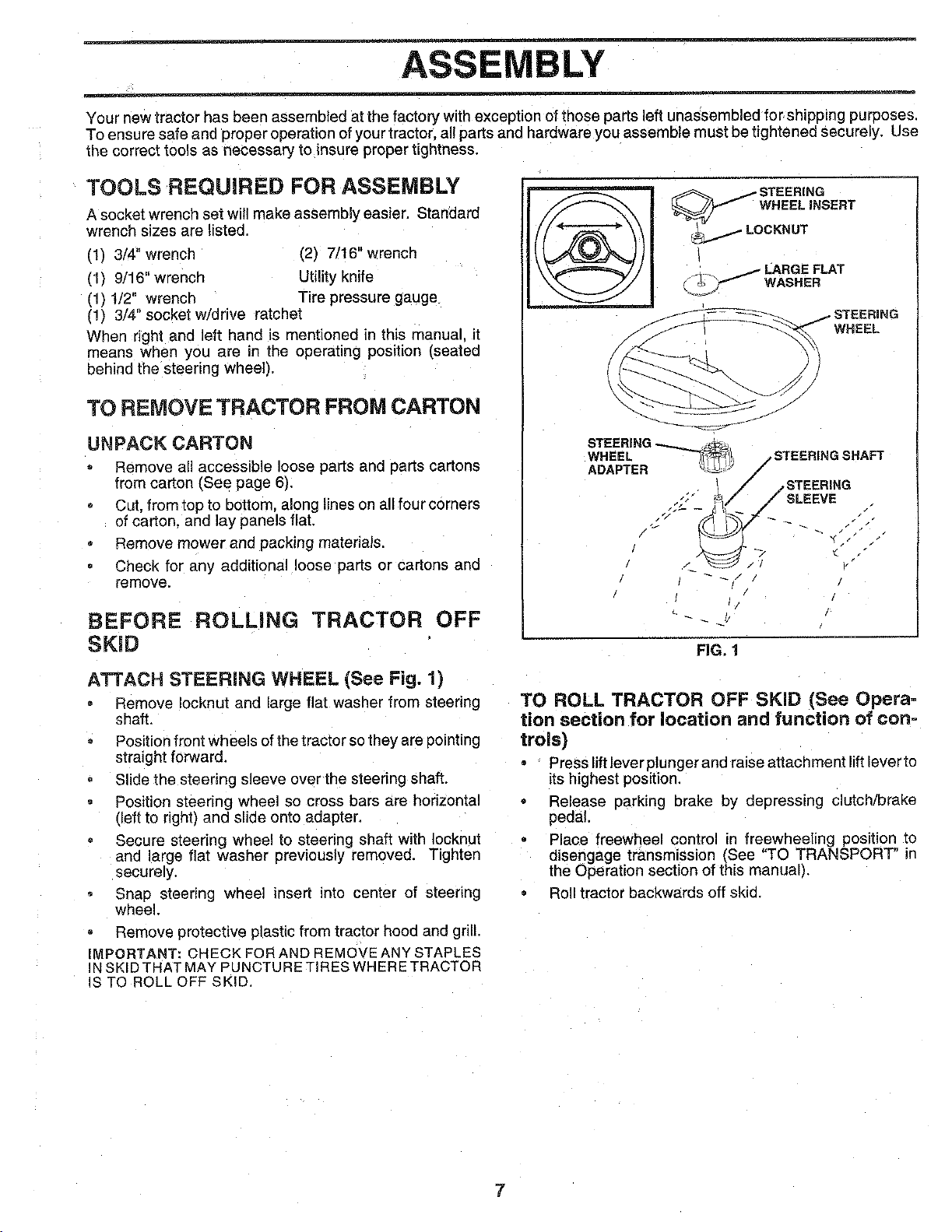
ATTACH STEERING WHEEL (See Fig. 1)
Remove Iocknut end large flat washer from steering
shaft.
Position front wheels of the tractor so they are pointing
straight forward.
Slide the steering sleeve over the steering shaft.
Position steering wheel so cross bars are horizontal
(left to right) and slide onto adapter.
Secure steering wheel to steering shaft with Iocknut
and large flat washer previously removed. Tighten
securely.
Snap steering wheel insert into center of steering
wheel.
Remove protective plastic from tractor hood and grill.
IMPORTANT: CHECK FOR AND REMOVE ANY STAPLES
kl SKID THAT MAY PUNCTURE TIRES WHERE TRACTOR
S TO ROLL OFF SKID,
FIG, 1
TO ROLL TRACTOR OFF SKiD (See Opera-
tion section for location and function of con=
trois)
Press lift lever plunger and raise attachment lift lever to
its highest position.
Release parking brake by depressing clutch/brake
pedal.
_laoe freewheel control ir freewheeling position to
disengage transmission (See "TO TRANSPORT" in
the Operation section of this manual).
= =_olltractor backwards off skid.
7
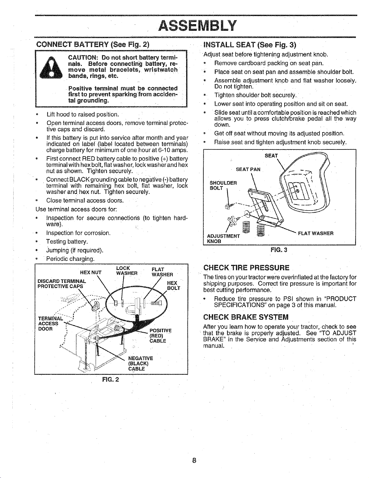
CONNECT BATTERY (See Fig. 2)
CAUTION: Do not short battery termi-
nals. Before connecting battery, re-
move metal bracelets, wristwatch
bands, rings, ete.
Positive termiRal must be connected
first to prevent sparking from acciden-
. . . taJ grouRdi_.na- .....
Lift hood to raised position.
Open terminal access doors, remove terminal protec-
tive caps and discard.
If this battery is put into servece after month and year
indicated on label (label located between terminals)
charge battery for minimum of one hour at 6-10 amps.
First connect RED battery cable to positive (+) battery
terminal with hex bolt. flatwasher, lockwasher and hex
nut as ShOWn. Tighten securely.
Connect BLACK grounding cable to negative (-) battery
terminal with remaining hex bolt. flat washer, lock
washer and hex nut. Tighten securely.
Close terminal access doors.
Use terminal access doors for:
Inspection for secure connections (to tighten hard-
ware).
inspection for corrosion.
Testing battery.
Jumping (if required).
Periodic charging.
HEX NUT
DISCARD TERMINAL \
PROTECTIVE CAPS
LOCK
WASHER
FLAT
WASHER
J HEX
BOLT
TERMINAL....
ACCESS
DOOR
POSITIVE
(RED)
CABLE
FiG. 2
(BLACK)
CABLE
iNSTALL SEAT (See Fig. 3)
Adjust seat before tightening adjustment knob.
Remove cardboard packing on seat pan.
Place seat on seat pan and assemble shoulder bolt.
Assemble adjustment knob and flat washer loosely.
Do not tighten.
Tighten shoulder bolt securely.
Lower seat intooperating position and sit on seat.
Slide seat until acomfortable position is reached which
allows you to press clutch/brake pedal all the way
down
Got off seat without moving its adjusted position.
Raise seat and tighten adjustment knob securely.
SEAT
\
SEAT PAN
SHOULDER
ADJUSTMENT
KNOB
FLAT WASHER
FIG, 3
CHECK TiRE PRESSURE
The tires on you rtractor were overinflated at the factory for
shipping purposes. Correct tire pressure is important for
best cutting performance.
Reduce tire pressure to PSI showr in "PRODUCT
SPECIFICATIONS" on page 3 of this manual.
CHECK BRAKE SYSTEM
After you learn how to operate your tractor, check to see
that the brake is properly adjusted. See "TO ADJUST
BRAKE" in the Service and Adjustments section of this
manual.
8
ASSEMBLY
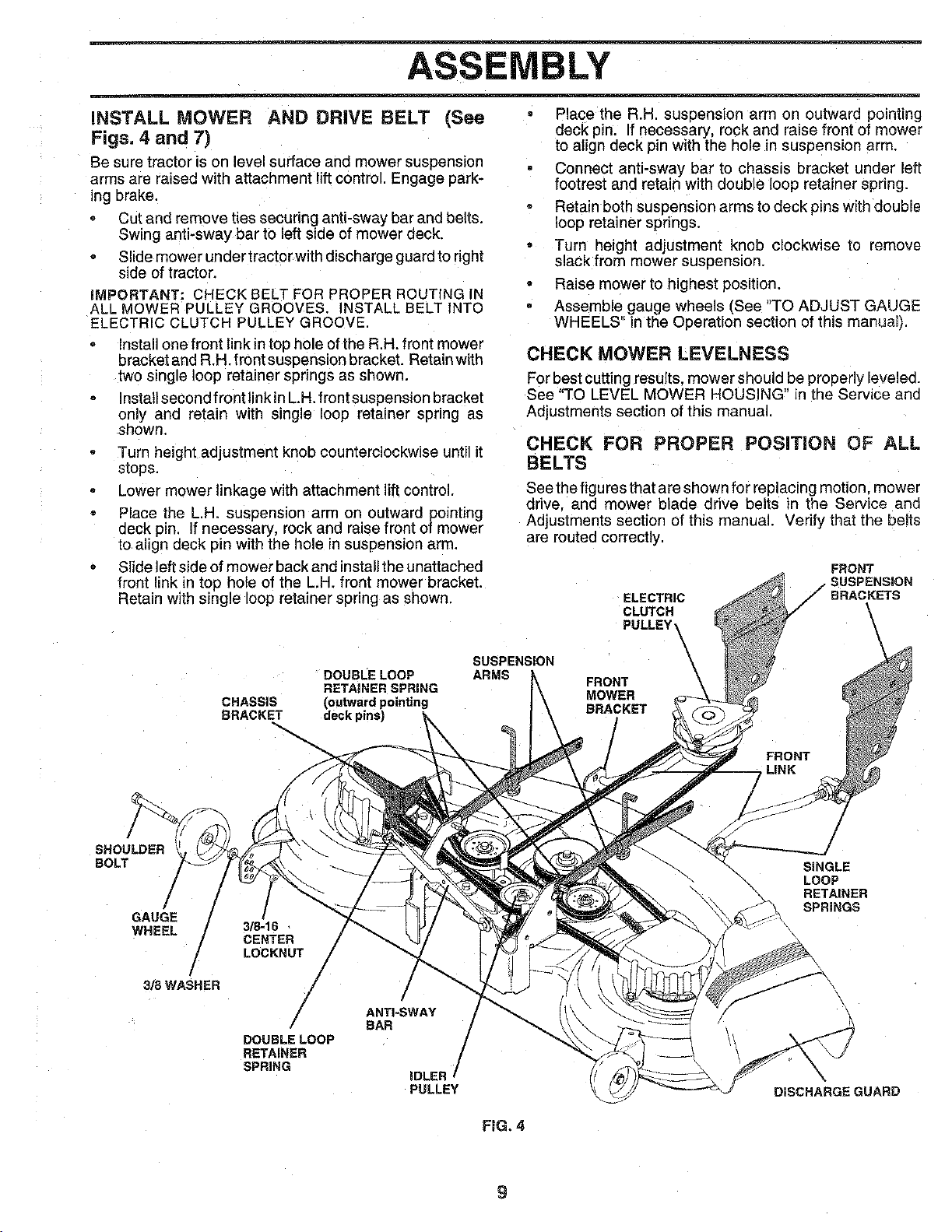
INSTALL MOWER AND DRIVE BELT (See
Figs, 4 and 7)
Se sure tractor is on level surface and mower suspension
arms are raised with attachment lift control. Engage park-
ing brake.
Cut and remove ties securing anti-sway bar and belts.
Swing anti-sway bar to left side of mower deck.
Slide mower under tractorwith discharge guard to right
side of tractor.
iMPORTANT: CHECK BELT FOR PROPER ROUTING IN
ALL MOWER PULLEY GROOVES. NSTALL BELT INTO
ELECTRIC CLUTCH PULLEY GROOVE,
Install one front link intop hole of the R,H, front mower
bracket and R.H. front suspension bracket. Retain with
two single loop retainer springs as shown.
Install second front linkin L.H. front suspension bracket
only and retain with single loop retainer spring as
shown.
Turn height adjustment knob counterclockwise until it
stops.
Lower mower linkage with attachment lift control.
Place the L.H. suspension arm on outward pointing
deck pin. If necessary, rock and raise front of mower
to, align deck pin with the hole in suspension arm.
Slide left side of mower back and installthe unattached
front link in top hole of the L.H. front mower bracket.
Retain with single loop retainer spring as shown.
DOUBLE LOOP
RETAJNER SPRING
CHASSIS (outwardpointing
BRACKET deck pins)
SUSPENSION
ARMS
• Place the R.H. suspension arm on outward pointing
deck pin. If necessary, rock and raise front of mower
to align deck pin with the hole in suspension arm.
Connect anti-sway bar to chassis bracket under left
footrest and retain with double loop retainer spnng.
• Retain both suspension arms to deck pins with double
loop retainer springs.
Turn height adjustment knob clockwise to remove
slack from mower suspension.
Raise mower to highest position.
Assemble gauge wheels [See "TO ADJUST GAUGE
WHEELS" in the Operation section of this manua0.
CHECK MOWER LEVELNESS
For best cutting results, mower should be properly leveled.
See "TO LEVEL MOWER HOUSING" in the Service ann
Adjustments section of this manual.
CHECK FOR PROPER POSITION OF ALL
BELTS
See the figures that are shown for replacing motion, mower
drive, and mower blade drive belts in the Service and
Adjustments section of this manual. Verify that the belts
are routed correctly.
ELECTRIC
CLUTCH
PULLEY_
FRONT
SUSPENSION
/eRACKETS
/
FRONT
MOWER
BRACKET
FRONT
LINK
/
SHOULDER
BOLT
/
GAUGE/ /
WHEEL 3/_16
CENTER
LOCKNUT
3/8WASHER / /
/ /
ANTI-SWAY
/ eAR
DOUBLELOOP /RETAINER
SPRING iDLER /
PULLEY
FiG. 4
SINGLE
\ LOOP
RETAINER
SPRINGS
\
DISCHARGE GUARD
BLY
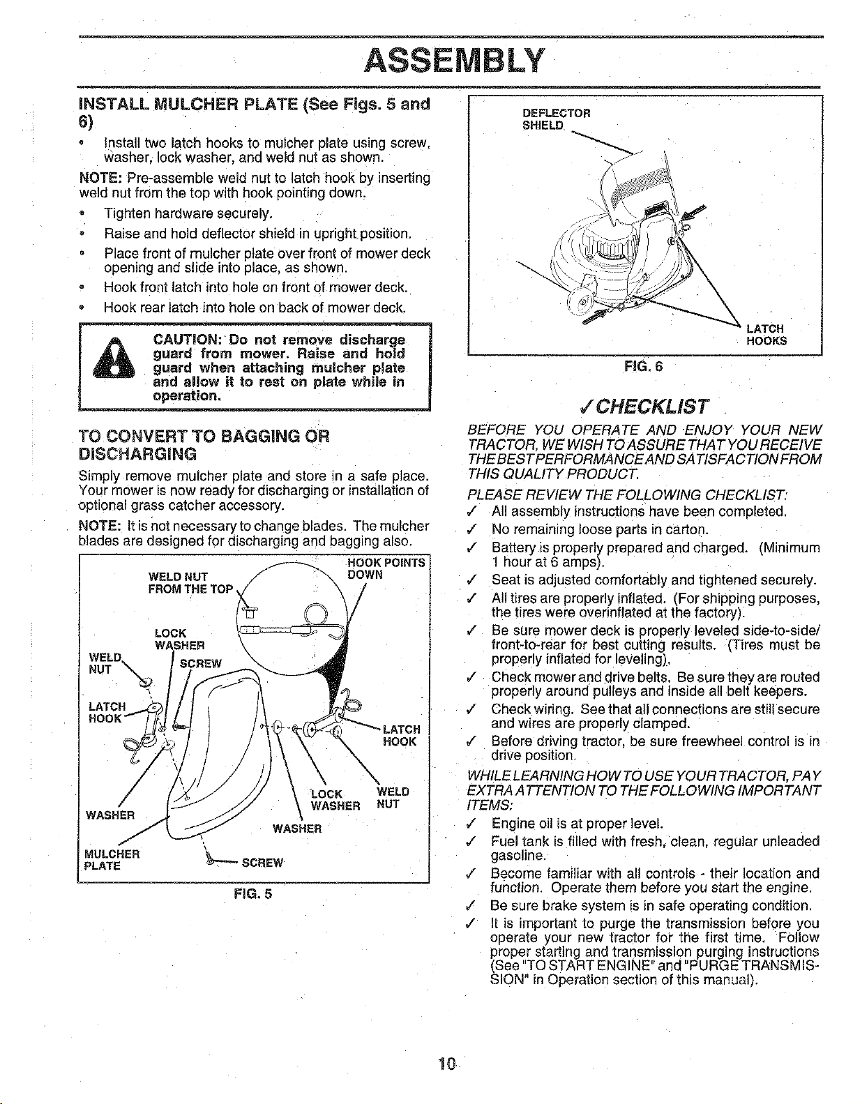
iNSTALL MULCHER PLATE (See Figs. 5 and
6)
Install two atch hooks to mulcher plate using screw.
washer, lock washer, and weld nut as shown.
NOTE" Pre-assemble weld nut to latch hook by inserting
weld nut from the top with hook pointing down.
Tighten hardware securely.
Raise and hold deflector shield in upright position.
Place front of mulcher plate over front of mower deck
opening and slide into place, as shown
Hook front latch into hole on front of mower deck
Hook rear latch into hole on back of mower deck.
I _ CAUTION:Do not remove discharge
_A guard from mower. Raise and hold
U _ guard when attaching mulcher plate
_ and al!ew it to rest on pJate while in
TO CONVERT TO BAGGING OR
DiSCHARGiNG
Simply remove rnulcher plate and store _n a safe oJace.
Your mower is now ready for discharging or installationof
optional grass catcher accessory.
NOTE: It is not necessary to change blades. The mulcher
blades are designed for discharging and bagging also.
HOOK POINTS-
WELD NUT _ DOWN
FROM THE TOP _[_ /
LOCK
WASHER
WELD
NUT
WASHER
/
MULCHER
PLATE
HOOK
_/_ LOCK
WASHER
WASHER
_J"-"-'SCREW
WELD
NUT
FIG. 5
DEFLECTOR
SHIELD
LATCH
HOOKS
FiG. 6
,/CHE CKLiS T
BEFORE YOU OPERATE AND ENJOY YOUR NEW
TRACTOR. WE WISH TO ASSURE THAT YOU RECEIVE
THE BEST PERFORMANCE AND SA TISFACTION FROM
THIS QUALITY PRODUCT.
PLEASE REVIEW THE FOLLOWING CHECKLIST."
,/ All assembly instructions nave been completed.
,/ No remaining loose parts in carton.
,/ Batteryis properly prepared and charged. (Minimum
1 hour at 6 amps).
¢" Seat is adjusted comfortably and tightened securely.
,/ All tires are properly inflated. (For shipping purposes.
the tires were overinflated at the factory).
¢ Be sure mower deck is properly leveled side-to-side/
front-to-rear for best cutting results. (Tires must be
properly inflated for leveling),
€ Check mower and drive belts. Be sure they ar_ routed
properly around pulleys and inside all belt keepers.
,/ Check wiring, See that all connections are still secure
and wires are properly clamped.
¢ Before driving tractor, be sure freewheel control is in
drive position
WHILE LEARNING HOW TO USE YOUR TRACTOR, PAY
EXTRA ATTENTION TO THE FOLLOWING IMPORTANT
ITEMS:
,/ Engine oil is at proper level.
,/ Fuel tank is filled with fresh, clean, regular unleaded
gasoline.
,/ Become familiar with all controls - their location and
function. Operate them before you start the engine.
J Be sure brake system is in safe operating condition.
v" it is important to purge the transmission before you
operate your new tractor foi" the first time. Follow
proper starting and transmission purging instructions
(See "TO START ENGINE" and "PURGE TRANSMIS-
SION" in Operation section of this manual).
10
OPERATION
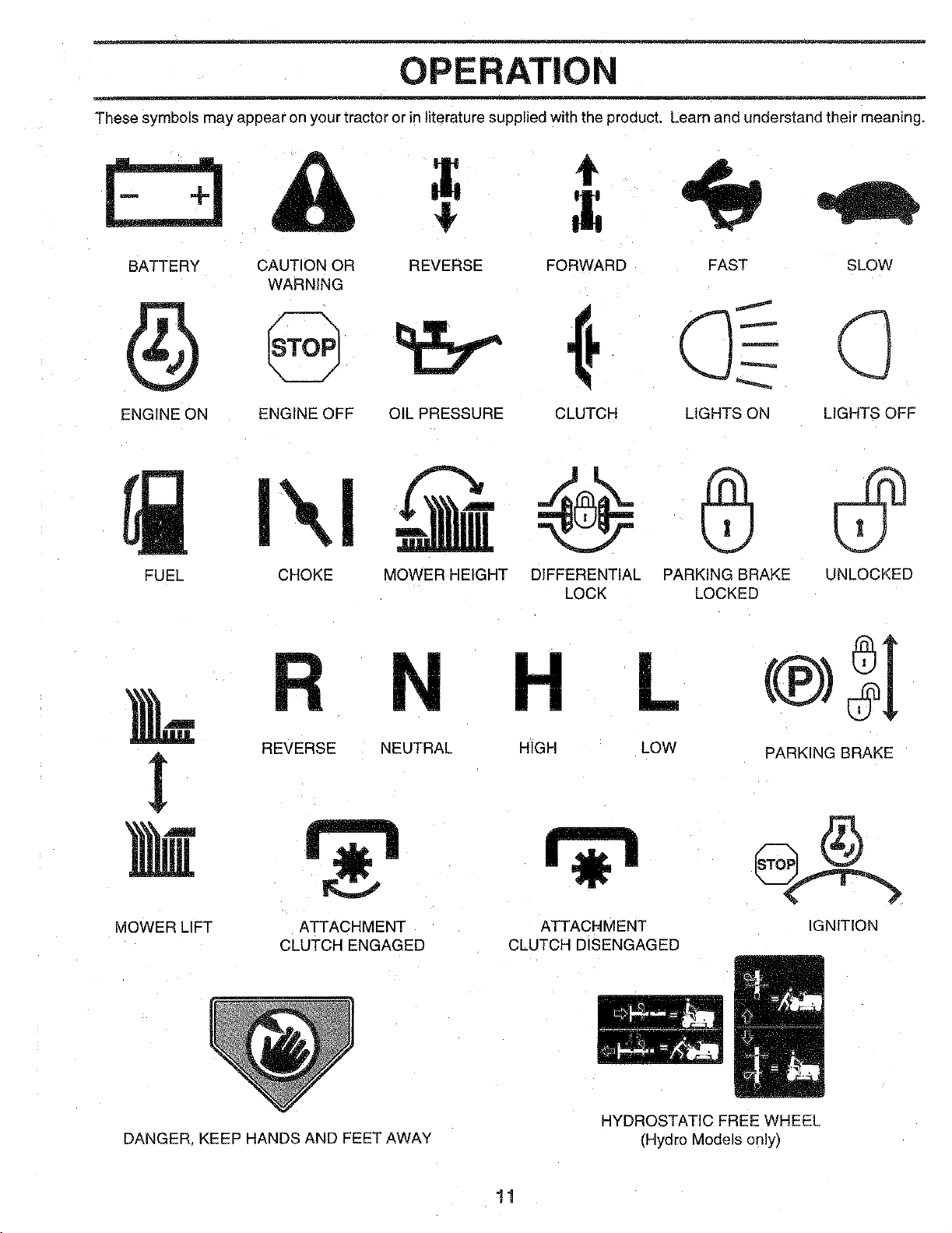
These symbols may appear on your tractor or in literaturesupplied with the product. Learn and understand their meaning.
4_
t
BATTERY CAUTION OR REVERSE FORWARD FAST SLOW
WARNING
ENGINE ON ENGINE OFF OIL PRESSURE CLUTCH LIGHTS ON LIGHTS OFF
FUEL CHOKE MOWER HEIGHT DIFFERENTIAL PARKING BRAKE UNLOCKED
LOCK LOCKED
REVERSE NEUTRAL
VIOWER LIFT
ATTACHMENT
CLUTCH ENGAGED
DANGER KEEP HANDS AND FEET AWAY
H L
HIGH LOW PARKING BRAKE
ATTACHMENT IGNITION
CLUTCH DISENGAGED
HYDROSTATIC FREE WHEEL
(Hydro Models only)
11
OPERATION
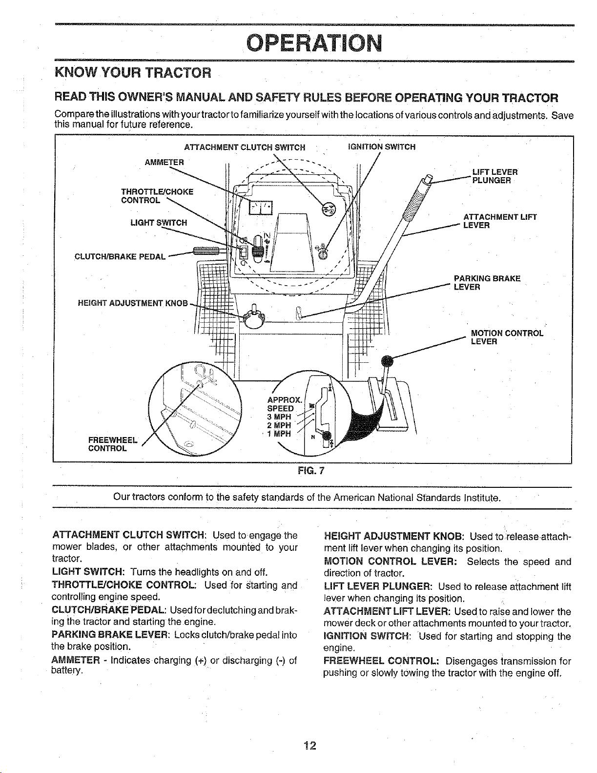
KNOW YOUR TRACTOR
READ THiS OWNER'S MANUAL AND SAFETY RULES BEFORE OPERATING YOUR TRACTOR
C_mpare the i__ustrati_nswith y_urtract_rt_ fami_iarize y_urse_fwiththe __cati__s _fVari_usc_ntr__sand adjustments" Save
this manual for future reference.
ATTACHMENT CLUTCH SWITCH
AMMETER
THROTTLE/CHOKE
CONTROL "_.
LIGHT SWITCH
CLUTCH/BRAKE PEDAL
HEIGHT ADJUSTMENTKNOB_
FREEWHEEL
CONTROL
t APPROX.
SPEED
I 1 MP_
/
IGNITION SWITCH
LiFT LEVER
UNGER
ATTACHMENT LIFT
PARKING BRAKE
MOTION CONTROL
LEVER
FIG. 7
Our tractors conform to the safety standards of the American National Standards Institute.
ATTACHMENT CLUTCH SWITCH: Used to engage the
mower blades, or other attachments mounted to your
tractor.
LIGHT SWITCH: Turns the headlights on and off.
THROTTLE/CHOKE CONTROL: Used for starting and
controlling engine speed.
CLUTCH/BRAKE PEDAL: Used fordeclutcHng and braK-
ing the tractor and starting the engine,
PARKING BRAKE LEVER: Locks clutch/brake pedal into
the brake position,
AMMETER - Indicates charging i÷) or discharging (-j of
battery.
HEIGHT ADJUSTMENT KNOB: Used to release attach-
ment lift lever when changing its position.
MOTION CONTROL LEVER: Selects the speed and
direction of tractor.
LiFT LEVER PLUNGER: Used to release attachment lift
lever when changing its position.
ATTACHMENT LiFT LEVER: Used to raise and lower the
mower deck or other attachments mounted to your tractor.
IGNITION SW_TCH: Used for starting and stopping the
engine,
FREEWHEEL CONTROL: Disengages transmission for
pushing or slowly towing the tractor with the engine off.
!2
OPERATION
_l_lll_ The opereti_ of any tractor can result in foreign objects thrown into_
_A_r___ n severe eye damage, Always wear safety glasses or eye shields while operating your I
_ tractor or perform,ing anyadjustments or repairs. We recommend a wide vision safety mask
I n=m "s '--tyg'"sesl _.
HOW TO USE YOUR TRACTOR
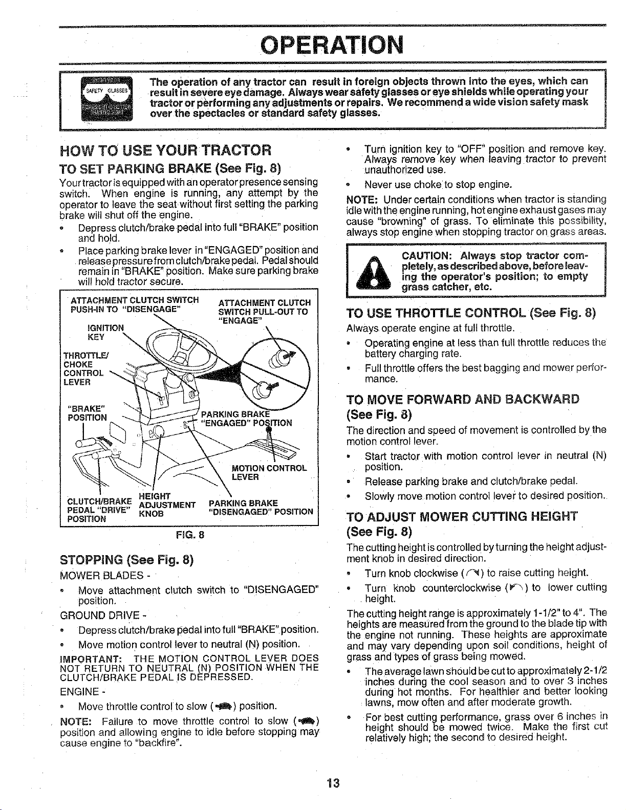
TO SET PARKING BRAKE (See Fig. 8)
Your tractoris equipped with an operator presence sensing
switch. When engine is running, any attempt by the
operator to leave the seat without first setting the parking
brake will shut off the engine,
Depress clutch/brake pedal intofull "BRAKE" position
and hold.
Place parking brake lever in "ENGAGED" position and
release pressure from clutch/brake pedal. Pedal shoula
remain in"BRAKE" position. Make sure parking brake
will hold tractor secure.
ATTACHMENTCLUTCHSWITCH
PUSH-INTO "DISENGAGE"
THROTTL_
CHOKE
CONTROL
LEVER
ATTACHMENT CLUTCH
SWITCH PULL-OUTTO
"ENGAGE"
"ENGAGED" POSITION
HEIGHT
CLUTCH/DRAKE ADJUSTMENT
PEDAL"DRIVE" KNOB
POSITION
PARKING DRAKE
"DISENGAGED"POSITION
FIG. 8
STOPPING (See Fig. 8)
MOWER BLADES -
Move attachment clutch switch to "DISENGAGED"
position.
GROUND DRIVE -
Depress clutch/brake pedal into full "BRAKE" position.
Move motion control lever to neutral (N) position.
iMPORTANT; THE MOTION CONTROL LEVER DOES
NOT RETURN TO NEUTRAL (N) POSITION WHEN THE
CLUTCH/DRAKE PEDAL IS DEPRESSED.
ENGINE -
Move throttle control to slow (,,_) position.
NOTE: Failure _o move throttle control to slow (,_k.]
position and allowing engine [o idle before stopping may
cause engine to "backfire".
Turn ignition key to "OFF" position and remove key.
Always remove key when leaving tractor to prevent
unauthorized use,
Never use choke to stop engine.
NOTE: Under certain conditions when tractor ts stand=rig
idle with the engine running, hot engine exhaust gases may
cause "browning" of grass. To eliminate this oessibility,
always stop engine when stopping tractor on grass areas.
TO USE THROTTLE CONTROL (See Fig. 8}
Always operate engine at full throttle.
• Operating engine at less than full throttle reduces the
battery charging rate.
Full throttle offers the best baggtng ano mower oerfor-
manGe.
TO MOVE FORWARD AND BACKWARD
(See Fig. 8)
The direction and speed of movement is controlled by the
motion control lever.
Start tractor with motion control lever in neutral (N)
position.
Release parking brake and clutch/brake oedal.
• Slowly move motion control lever to desired position.
TO ADJUST MOWER CUTTING HEIGHT
(See Fig. 8)
The cutting height is controlled by turning the height adjust-
ment knob in desired direction.
Turn knob clockwise (f_) to raise cutting height.
Turn knob counterclockwise (F'_)to lower cutting
height,
The cutting height range is approximately 1-1/2" to 4" The
heights are measured from the ground to the blade tip with
the engine not running. These heights are approximate
and may vary depending upon soil conditions height of
grass and types of grass being mowed.
The average lawn should be cut to approximately 2-1/2
inches during the cool season and [o over 3 inches
during hot months. For healthier and better looking
lawns, mow often and after moderate growth.
For best cutting performance, grass over 6 inches in
height should be mowed twice. Make the first cut
relatively high; the second to desired height.
13
OPERATION
TO ADJUST GAUGE WHEELS (See Fig. 9)
Adjust gauge wheels with tractor on a flat level surface,
Adjust mower to desired cutting height (See "TO
ADJUST MOWER CUTTING HEIGHT" in the Opera-
tion section of this manual).
With mower in desired height of cut position, gauge
wheels should be assembled so they are slightly off
the ground. Install gauge wheel in appropriate hole
with shoulder bolt. 3/8 washer, and 3/8-16 Iocknut and
tighten securely.
Reoeat for opposite side installing gauge wheel in
same adjustment hole.
GUAGE
WHEEL
MOUNTING
BRACKEJ"
318-16
GAUGE WHEEL '''`-'_
,f
J
SHOULDER BOLT
TO OPERATE ON HILLS
_ h'dls with s_pes greater than 15° and
Choose the slowest speea before starting up or down
hills.
Avoid stopping or changing speed on hills.
If slowing is necessary, move throttle control lever to
slower position.
If stopping is absolutely necessary, push clutch/brake
pedal quickly to brake position and engage parking
brake.
Move motion control lever to neutral (N) position.
IMPORTANT: THE MOTION CONTROL LEVER DOES
NOT RETURN TO NEUTRAL (N) POSITION WHEN THE
CLUTCH/BRAKE PEDAL iS DEPRESSED.
To restart movement, slowly release parking brake and
clutch/brake pedal.
Slowly move motion control lever to slowest setting.
Make all turns slowly.
FiG. 9
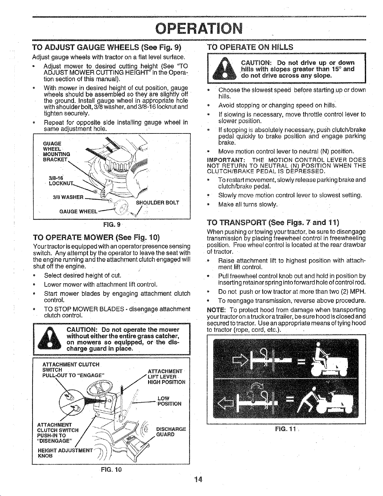
TO OPERATE MOWER (See Fig. 10)
You rtractorisequipped with an operatorpresence sensing
switch. Any attempt by the operator to leave the seat with
the engine running and the attachment clutch engaged will
shut off the engine.
Select desired height of cut.
Lower mower with attachment lift control
Start mower blades by engaging attachment clutch
control.
TO STOP MOWER BLADES - disengage attachment
clutch control.
CAUTION: Do not operate the mower
without either the entire grass catcher,
on mowers so equipped, or the dis-
charge guard in place.
ATTACHMENT CLUTCH
SWITCH ATTACHMENT
PULL-OUT TO "ENGAGE" / LIFT LEVER
\ -I HIGH POSiTiON
/-
TO TRANSPORT (See Figs. 7 and 11)
When pushing or towing your tractor, be sure to disengage
ttansmissioth by placing freewheel control in freewheeling
position. Free wheel control is located at the rear drawbar
of tractor.
Raise attachment lift to highest position with attach-
ment lift control,
Pull freewheel control knob out and hold in position by
inserting retainer spnng into forward hole ofcontrol rod.
Do not push or tow tractor at more than two (2) MPH.
To reengage transmission, reverse above procedure.
NOTE: To protect hood from damage when transporting
your tractor on atruckor a trailer, be sure hood isclosed and
secured to tractor. Use an appropriate means oftying hood
to tractor (rope. cord. etc.).
LOW
- POSITION
f
ATTACHMENT
CLUTCH SWITCH
PUSH-IN TO
"DISENGAGE" /
/
HEIGHTADJUSTMEHT_
KNOB
DISCHARGE
GUARD
FiG. 10
14
FIG. 1!
OPERATION
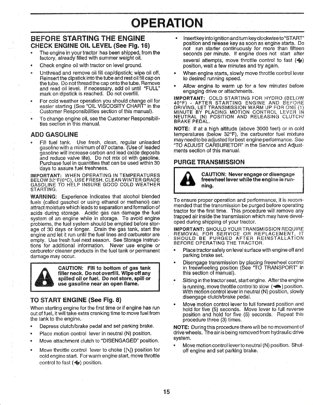
BEFORE STARTING THE ENGINE
CHECK ENGINE OiL LEVEL (See Fig. 16)
The engine in your tractor has been shipped, from the
factory, already filled with summer weight oil.
Check engine oil with tractor on level ground.
Unthread and remove oil fill cap/dipstick; wipe oi_ off.
Reinsert the dipstick into the tube and rest oil fill cap on
the tube. Do not thread the cap onto the tube. Remove
and read oil level. If necessary, add oil until "FULL"
mark on dipstick is reached. Do not overfill
• For cold weather operation you should change oil for
easier starting (See "OIL VISCOSITY CHART" in the
Customer Responsibilities section of this manual).
To change engine oil. see the Customer Responsibili-
ties sect!on in this manual.
ADD GASOLINE
Fit! fuel tank. Use fresh, clean, regular unleadee
gasoline with a minimum of 87 octane. (Use of leaded
gasoline will increase carbon and lead oxide deposits
and reduce valve life). Do not mix oil with gasoline.
Purchase fue! in quantities that can be used within 30
days to assure fuel freshness.
IMPORTANT: WHEN OPERATING iN TEMPERATURES
BELOW 32°Ft0°C). USE FRESH CLEAN WINTER GRADE
GASOLINE TO HELP INSURE GOOD COLD WEATHER
STARTING.
WARNING: Experience indicates that alcohol blended
fuels (called gasohol or using ethanol or methanol) can
attract moisture which leads to separation and formation of
acids during storage. Acidic gas can damage the fuel
system of an engine while in storage. To avoid engine
problems, the fuel system should be emptied before stor-
age of 30 days or longer. Drain the gas tank, start the
engine and let it run until the fuel lines and carburetor are
empty. Use fresh fuel next season. See Storage Instruc-
tions for additional information. Never use engine or
carburetor cleaner products in the fuel tank or permanent
damage may occur.
TO START ENGINE (See Fig. 8)
When starting engine for the first time or if engine has run
out of fuel it will take extra cranking time to move fuel from
the tank to the engine.
Depress clutch/brake pedal and set parking brake.
Place motion contro lever in neutral (N) position.
Move attachment clutch to "DISENGAGED" position.
Move throttle control lever to choke (t\J) position for
cold engine start. For warm engine start, move throttle
• Insertkeyintoignitionandturnkeyclockwiseto"START"
position and release key as soon as engine starts. Do
not run starter continuously for more than fifteen
seconds per minute, if engine does not start after
several attempts, move throttle control to fast (,@)
position, wait a few minutes and try again.
When engine starts, slowly move throttle control lever
to desired running speed.
• Allow engine to warm up for a few minutes' before
engaging drive or attachments.
IMPORTANT; COLD STARTING FOR HYDRO (BELOW
40°F) - AFTER STARTING ENGINE AND BEFORE
DRIVING. LET TRANSMISSION WARM UP FOR ONE (1/
MINUTE BY PLACING MOTION CONTROL LEVER IN
NEUTRAL (N) POSITION AND RELEASING CLUTCH/
BRAKE PEDAL.
NOTE: If at a high altitude (above 3000 feet) or in cold
temperatures (below 32°F), the carburetor fuel mixture
mayneedtobeadjustedforbest enginepertormance See
"TO ADJUST CARBURETOR" in the Service and Adjust-
ments section of this manual.
PURGE TRANSMiSSiON
To ensure proper operation and performance, it is recom-
mended that the transmission be purged before operating
tractor for the first time. This procedure will remove any
trapped air inside the transmission which may have devel-
oped during shipping of your tractor.
IMPORTANT: SHOULD YOU RTRANSMISSION REQU RE
REMOVAL FOR SERVICE OR REPLACEMENT iT
SHOULD BE PURGED AFTER REINSTALLATION
BEFORE OPERATING THE TRACTOR.
Place tractor safely on level surface with engine off and
parking brake set.
Disengage transmission by placing freewheel comro]
in freewheeling position (See "TO TRANSPORT" in
this section of manual).
Sitting inthe tractor seat. start engine. After the engine
is running, move throttle control to slow (_) position.
With motion control lever in neutral (N) position, slowly
disengage clutch/brake pedal.
Move motion control lever to full forward position and
hold for five (5) seconds. Move ever to full reverse
position and hold for five (5) seconds. Repeat this
procedure three (3) times.
NOTE: Dudng this procedure there will be no movement of
drive wheels. The airis being removed from hydraulic drive
system.
, Move motion control lever to neutra' (N) position. Shut-
off engine and set parking brake.
control to fast (,_) position.
t5
OPERATION
Engage transmission by placing freewheel control in
driving position (See "TO TRANSPORT" in this section
of manual).
Sitting in the tractor seat. start engine. After the engine
is running, move throttle control to half (1/2) speed.
With motion control lever in neutral IN) position, slowly
disengage clutch/brake pedal.
Slowly move motion control lever forwarc after the
tractor moves approximately five (5) feet, slowly move
motion control lever to reverse position. After the
tractor moves approximately five (5) feet return the
motion control lever to the neutral (N) position. Repeat
this procedure with the motion control lever three (3)
times.
Your tractor is now purged and now ready for normal
operation.
MOWING TIPS
Tire chains cannot be used when the mower housing
]s attached to tractor.
Mower should be oropeny leveled for best mowing
performance. See "TO LEVEL MOWER HOUSING" in
the Service and Adjustments section of this manual.
The left hand side of mower Should be used for trim-
ming.
Drive so that clippings are discharged onto the area
that has been cut Have the cut area to the right of the
machine This will resultin a more even distribution of
clippings and more uniform cutting.
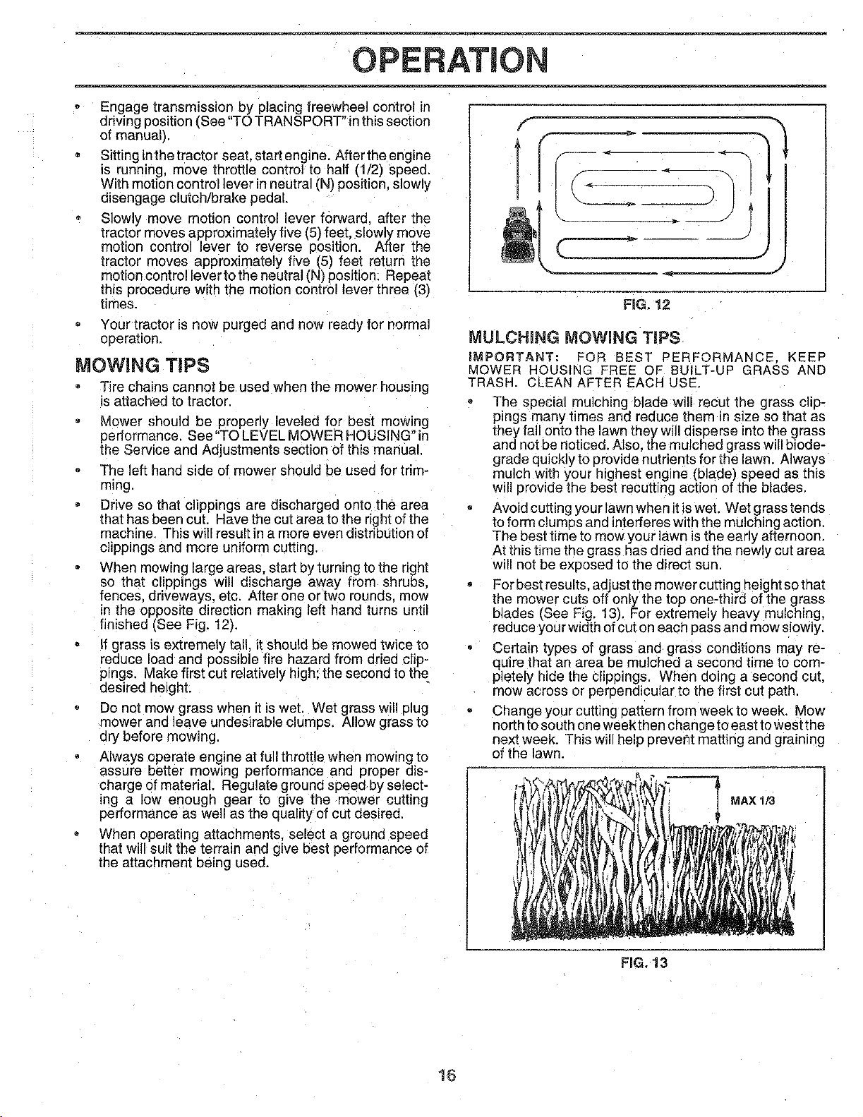
When mowing large areas, start by turning to the right
so that clippings wil discharge away from shrubs.
fences, driveways, etc, After one ortwo rounds, mow
n the opposite direction making left hand turns until
finished (See Fig. 12).
If grass is extremely tall. itshould be mowed twice to
reduce load and possible fire hazard from dried c ip-
pings. Make first cut relatively high: the second to the
desired height.
Do not mow grass when it iswet. Wet grass will plug
mower and leave undesirable clumps. Allow grass to
dry before mowing.
Always operate engine at full throttle when mowing to
assure better mowing performance and proper dis-
charge of material. Regulate ground speed by select-
ing a low enough gear to give the mower cutting
performance as well as the quality of cut desired,
When operating attachments, select a ground speed
that will suit the terrain and give best performance of
the attacnment being used.
FIG, 12
MULCHING MOWING TiPS
iMPORTANT: FOR BEST PERFORMANCE KEEP
MOWER HOUSING FREE OF BUiLT-UP GRASS AND
TRASH CLEAN AFTER EACH USE
The special mulching blade will recut the grass clip-
pings many times and reduce them in size so that as
they fall onto the lawn they will disperse into the grass
and not be noticed. Also, the mulched grass will biode-
grade quickly to orovide nutrients for the lawn. Always
mulcn with your highest engine (blade) speed as this
will provide the best recutting action of the blades,
Avoid cutting you rlawn when itis wet. Wet grass tends
to form clumps and in_terfereswith the mulching action.
The best time to mow your lawn is the early afternoon.
At this time the grass has dried and the newly cu[ area
will not be exposed to the direct sun.
For best results, adjust the mower cutting height so that
the mower cuts off only the top one-third of the grass
blades (See Fig. 13). For extremely heavy mulching,
reduce your width of cut on each pass and mow slowly.
Certain types of grass and grass conditions may re-
quire that an area be mulched a second time to com-
pletely hide the clippings. When doing a second cut.
mow across or perpendicular to the first cut path.
Change your cutting pattern from week to week. Mow
north to south one week then change to east to west the
next week, This willhelp preveht matting and graining
of the lawn.
"_ MAX 1/3
FiG, 13
16
CUSTOMER RESPONSIBILITIES
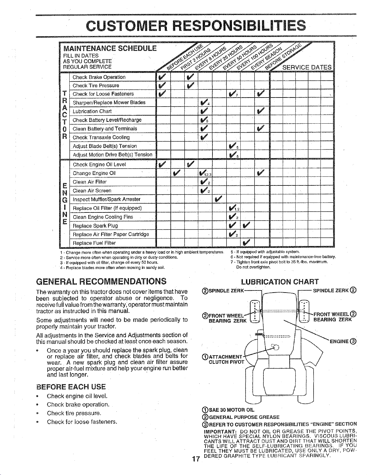
MAINTENANCE SCHEDULE
FILLIN DATES
ASYOUCOMPLETE
REGULARSERVICE
SERVICE DATES
CheckBrakeOperation
CheckTire Pressure _ if
Checkfor LooseFasteners
Sharpen/ReplaceMowerBiades
LubricationChart
CheckBatteryLevel/Recharge
CleanBattery-andTerminals
CheckTransaxleCooling
Adjust BladeBelt(s)Tension
Adjust MotionDriveBelt(s)Tension
Check EngineOilLevel _
ChangeEngineOil _
CleanAir Fi{ter
Cean Air Screen
InspectMuffler/SparkArrester
ReplaceOil Filter(if equipped)
CleanEngineCoolingFins
ReplaceSparkP]ug
ReplaceAir FilterPaperCartridge
ReelaceFuelFilter
I/7 V'
V"
I#
V'5
m_m _sBmz
V'2
v'
v'
v'2
v' v'
m
m
1 - Change more often when opera[ing under a heavy load or in high amDter t_temperatures
2 - Service more o_en when operating in dirty or dusty conditions.
3 - if equipped with oil fi_ter, cnange oil every 50 hours.
4 - Re_ ace blades more o_en when mowing in sandy soJ
5 - It equipped with adjustable system
S- Not reeuired if eauiDDed with maintenance-free battery.
7 - Tighten front a×ie _ivot boil to 35 ft,-Ibs, ma×lrnum.
Do not over[ighten.
GENERAL RECOIVIMENDATIONS
The warranty on this tractor does not cover items that have
beer subjected to operator abuse or negligence. To
receive full valuefrom the warranty, operator must maintain
tractor as instructed in this manual.
Some adjustments will need to be made periodically to
properly maintain your tractor.
All adjustments in the Service and Adjustments section of
this manua! should be checked at least once each season.
Once a year you should replace the spark plug, clean
or replace air filter, and check blades and belts for
wear. A new spark plug and clean air filter assure
proper air-fuel mixture and help your engine run better
and last longer.
BEFORE EACH USE
Check eng meoil level.
Check brake operatlon.
Check tire pressure.
Check for loose fasteners.
LUBRiCATiON CHART
BEARING ZERK
C
CLUTCH PIVOT
®
(_)SAE 30 MOTOR OIL
®GENERAL PURPOSE GREASE
(_)REFER TO CUSTOMER RESPONSIBiLiTiES "ENGINE" SECTION
IMPORTANT: DO NOT OiL OR GREASE THE PIVOT POINTS,
WHICH HAVE SPECIAL NYLON BEARINGS. VISCOUS LUBRI-
CANTS WILL ATTRACT DUST AND DiRT THAT WILL SHORTEN
THE LIFE OF THE SELF-L JBRICATING BEARINGS, IF YOU
FEEL THEY MUST BE LUBRICATED= USE ONLY A DRY, PeW
7 DERED GRAPHITE TYPE LL _RICANT SPARINGLY.
CUSTOMER
TRACTOR
Always observe safety ruleswhen performingany mainte-
nance.
BRAKE OPERATION
If tractor requires more than six 16)feet stopping distance
at high speed in highest gear, then brake must be adjusted.
(See "TO ADJUST BRAKE" in the Service and Adjust-
ments section of this manual).
TIRES
Maintain proper air pressure in all tires (See "PROD-
UCT SPECIFICATIONS" on page 3 of this manual).
Keep tires free of gasoline, oil. or insect control chemi-
cals which san harm rubber.
Avoid stumps, stones, deep ruts. sharp objects and
other hazards that may cause tire damage.
8LADE CARE
For best results mower blades must be kept sharp. Re-
place bent or damaged blades.
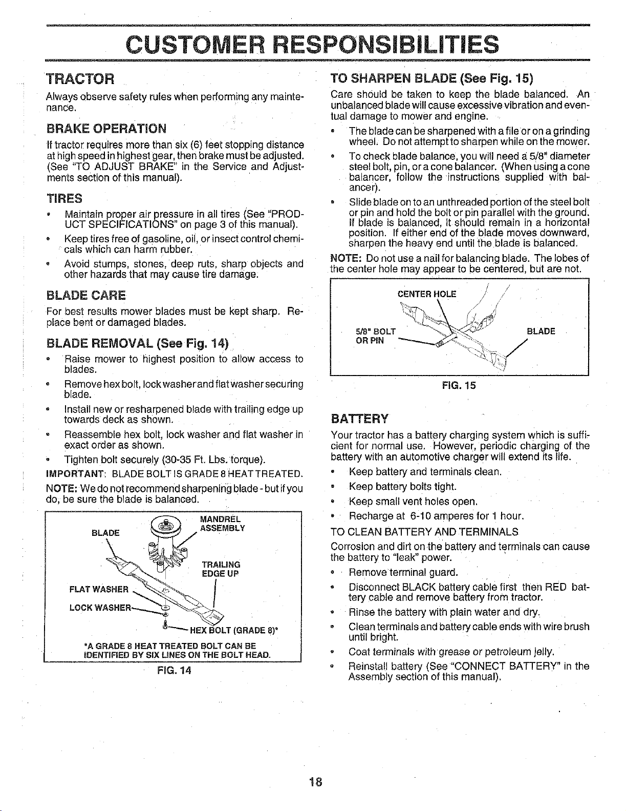
8LADE REMOVAL (See Fig, 14)
Raise mower to highest eosition to allow access [o
blades.
Remove hex bolt. lock washer and flat washer securing
blade.
Install new or resharpened blade with trailing edge up
towards deck as shown.
Reassemble hex bolt, lock washer and flat washer in
exact order as shown.
Tighten bolt securely (30-35 Ft. Lbs. torque).
iMPORTANT: BLADE BOLT IS GRADE 8 HEATTREATED.
NOTE: We donot recommend sharpening blade- but ifyou
do. be sure the blade isbalanced.
BLADE
FLAT WASHE_R_ _'_
LOCK WASHER',-._.
_ MANDREL
ASSEMBLY
TRAILING
EDGE UP
_LT (GRADE 8)*
*A GRADE 8 HEAT TREATED BOLT CAN BE
iDENTIFiED BY SIX LINES ON THE BOLT HEAD.
FiG, 14
TO SHARPEN BLADE (See Fig, 15)
Care should be taken to keep the olade balanced. An
unbalanced blade willcause excessive vibration and even-
tual damage to mower and engine.
The blade can be sharpened with a fileor on a gnnding
wheel. Do not attempt to sharpen while on the mower.
To check blade balance, you will need a_5/8" diameter
steel bolt. Din.or a cone balancer. {When using a cone
balancer, follow the instructions supplied with bal-
ancerj.
Slide blade on to an unthreaded portion of the steel bolt
or pin and hold the bolt or pm parallel with the grouna.
if blade is balanced, it should remain in a horizontal
position. If either end of the blade moves downward.
sharpen the heavy end until the blade is balanced.
NOTE: Do not use a nail for balancing blade, The lobes of
the center hole may appear to be centered, but are not.
CENTER HOLE
5/8" BOLT BLADE
OR PIN J
FIG. 15
BATTERY
Your tractor has a battery charging system which is suffi-
cient for normal use, However. periodic charging of the
battery with an automotive charger will extend its life,
Keep battery and terminals clean.
Keep battery bolts tight.
Keep small vent holes open.
Recharge ai 6-10 amperes for 1 nour.
TO CLEAN BATTERY AND TERMINALS
Corrosion and dirt on the battery and terminals can cause
the battery to "leak" power.
Remove terminal guard.
Disconnect BLACK battery cable first then RED bat-
tery cable and remove battery from tractor.
Rinse the battery with plain water and dry.
Clean terminals and battery cable ends with wire brush
until bright.
Coat terminals with grease or petroleum jelly.
Reinstall battery (See "CONNECT BATTERY" m the
Assembly section of this manual).
18
CUSTOMER RESPONSIBILITIES
TRANSAXLE COOLING
The fan and cooling fins of transmission should be kept
clean to assure proper cooling.
Do not attempt to clean fan or transmission while engine is
running or while the transmission is hot.
Inspect cooling fan to be sure fan blades are intact and
clean.
Inspect cooling fins for dirt. grass clippings and other
materials. To prevent damage to seals, do not use
compressed air or high pressure sprayer to clean
cooling fins.
TRANSAXLE PUMP FLUID
The transaxle was sealed at the factory and fluid mainte-
nance is not required for the life of the transaxle. Should the
transaxle ever leak or require servicing, contact your near-
est authorized service center/department.
V-BELTS
Check V-belts for deterioration and wear after 100 hours of
operation and replace if necessary. The belts are not
adjustable. Replace belts if they begin to slip from wear.
ENGtNE
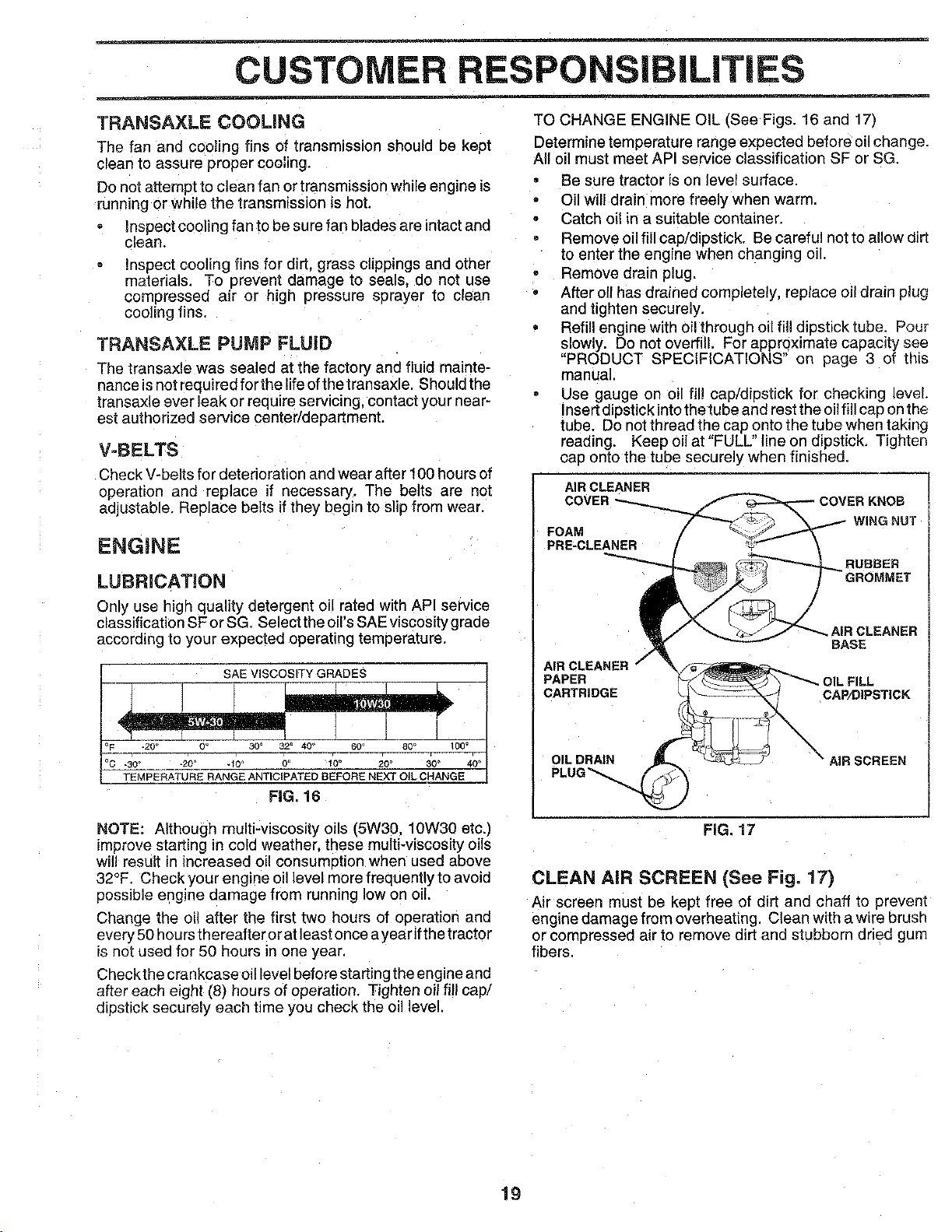
LUBRiCATiON
Only use high quality detergent oil rated with API service
classification SFor SG Select the oil's SAE viscosity grade
according to your expected operating temperature.
SAE ViSCOSiTY GRADES
°F_ -20' O" 30 _ 32' 40 _ 60' 80 ° 100 _
r
°C 30' _20° -10' 0° 10 ° 20 ° 30 ° 40 °
TEMPERATURE RANGE ANTiCiPATED BEFORE NEXT OiL CHANGE
FIG. 16
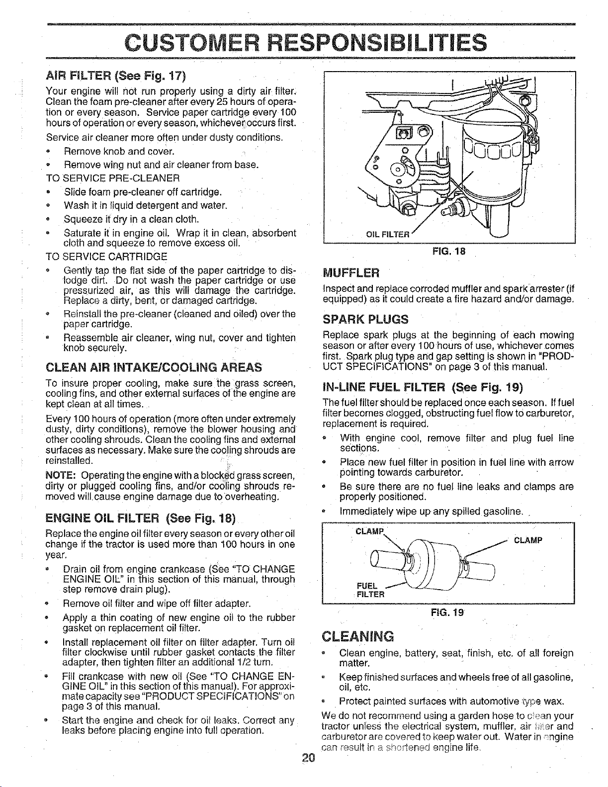
TO CHANGE ENGINE OIL (See Figs. 16 and 17)
Determine temperature range expected before oil change.
All oil must meet API service classification SF or SG.
Be sure tractor is on level surface.
Oil will drain more freely when warm.
Catch oil in a suitable container.
= Remove oil fill cap/dipstick. Be careful not to allow dirt
to enter the engine when changing oil.
Remove drain plug.
• After oil has drained completely, replace oil drain plug
and tighten securely.
Refill engine with oil through oil fill dipstick tube. Pour
slowly. Do not overfill. For approximate capacity see
"PRODUCT SPECIFICATIONS" on page 3 of this
manua
Use gauge on oil ill! cap/dipstick for checking level.
Insert dipstick into the tube and rest the oil fill cap on the
tube. Do not thread the cap onto the tube when taking
reading. Keep oil at "FULL" line on dipstick. Tighten
cap onto the tube securely when finished.
AIR CLEANER
COVER
FOAM
PRE-CLEANER
WING NUT
AIR CLEANER
BASE
PAPER . FILL
CARTRIDGE CAP/DIPSTICK
OIL DRAIN
PLUG_
AIR SCREEN
NOTE: Although multi-viscosity oils (5W30. 10W30 etc.)
rmprove starting in cold weather, these multi-viscosity oils
will result in increased oil consumotion when used above
32°F. Check your engine oil level more frequently to avoic
possible engine damage from running low on oil.
Change the oil after the first two hours of operation and
every 50 hours thereafferorat least once ayearifthe tractor
s not used for 50 hours in one year.
Checkthe crankcase oil level before starting the engine and
after each eight (8) hours of operation. Tighten oil fill cap/
dipstick securely each time you check the oil level.
FIG. 17
CLEAN AiR SCREEN (See Fig. 17)
Air screen must be kept free of dirt and chaff [o prevent
engine damage from overheating. Clean with a wire brush
or compressed air to remove dirt and stubborn dried gum
fibers.
19
AiR FILTER (See Fig, 17)
Your engine wil! not run properly using a dirty air filter,
Clean the foam pre-cleaner after every 25 hours of opera-
tion or every season. Service paper cartridge every 100
hours of operation or every season, whicheveroccurs first,
Service air cleaner more often under dusty conditions.
Remove knob and cover.
Remove wing nut and air cleaner trom base.
TO SERVICE PRE-CLEANER
Slide foam ore-cleaner off cartridge.
Wash it in liquid detergent and water,
Squeeze it dry in a clean cloth
Saturate it in engine oil. Wrap it in clean, absorbent
cloth and squeeze to remove excess oil.
TO SERVICE CARTRIDGE
Gently tap the fiat side of the paper cartridge to dis-
lodge dirt. Do not wash the paper cartridge or use
pressurized air. as this will damage the cartridge.
Replace a dirty, bent. or damaged cartridge.
Reinstall the ere-cleaner [cleaned and oiled) over the
paper cartriage.
Reassemble air cleaner, w_ng nu[, cover and tighten
knob securely.
CLEAN AIR INTAKF.JCOOLING AREAS
To insure proper cooling, make sure the grass screen.
cooling fins, and other external surfaces of the engine are
kept clean at all times.
Every !00 hours of operation (more often under extremely
dusty, dirty conditions), remove the blower housing and
other cooling shrouds. Clean the cooling fins and external
surfaces as necessary. Make sure the cooling shrouds are
reinstalled
NOTE: Operating the engine with a blocked grass screen,
dirty or plugged cooling fins, and/or cooling shrouds re-
movea will cause engine damage due to overheating.
ENGINE OiL FILTER (See Fig. 18)
Replace the engine oil filter every season or every other oi!
change if the tractor is used more than 100 hours in one
year,
Drain oil from engine crankcase (See "TO CHANGE
ENGINE OIL" in this section of this manual, through
step remove drain ptug/.
Remove oil filter and wipe off filter adapter.
Apply a thin coating of new engine oil to the rubber
gasket on replacement oil filter.
Install replacement oil filter on filter adapter. Turn oil
titter clockwise until rubber gasket contacts the filter
aaapter, then tighten tilter an additional 1/2 turn,
Fill crankcase with new oil tSee "TO CHANGE EN-
GINE OIL" in this section of this manua0. For approxi-
mate capacity see "PRODUCT SPECIFICATIONS" on
3age 3 of this manual.
Start the engine and check for oil leaks. Correct any
eaks before placing engine into fu!l operation.
20
MUFFLER
Inspect and replace corroded muffler and spark arrester (if
equipped) as it could create a fire hazard and/or damage.
SPARK PLUGS
Replace spark plugs at the beginning of each mowing
season or after every 100 hours of use. whichever comes
first. Spark plug type and gap setting is shown in "PROD-
UCT SPECIFICATIONS" on page 3 of this manuat.
IN-LINE FUEL FILTER (See Fig. 19)
The fuel filter should be replaced once each season. Iffuel
filter becomes clogged, obstructing fuel flow to carburetor
replacement is required.
With engine cool. remove IiIter and plug fuel line
sections,
Place new fuel filter in position in fuel line with arrow
pointing towards carburetor.
Be sure there are no fuel line leaks and clamps are
propeny positioned.
Immediately wipe up any spilled gasoline.
CLAMP
FILTER
CLAMP
FIG. 19
CLEANING
Clean engine, battery, seat, finish, etc. of a!! foreign
matter.
Keep finished surfaces and wheels free of a!l gasoline,
oil. etc,
Protect painted surfaces with automotive _ype wax.
We do not recommend using a garden hose to c _n your
tractor unless the electrical system, muffler, air .,er and
carouretor are covered to _<eepwater out. Water in :nglne
can result _n_ :_,_en_ed engine life
SERVICE AND ADJUSTMENTS
CAUTION: BEFORE PERFORMING ANY SERVICE OR ADJUSTMENTS:
Depress clutch/brake pedal fully and set parking brake.
Place motion control lever in neutral (N) position.
Place attachment clutch in "DISENGAGED" position.
, Turn ignition key "OFF" and remove key,
Make sure the blades and all moving parts have completely stopped.
Disconnect spark plug wire from spark plug and place wire where it cannot come in contact with
plug.
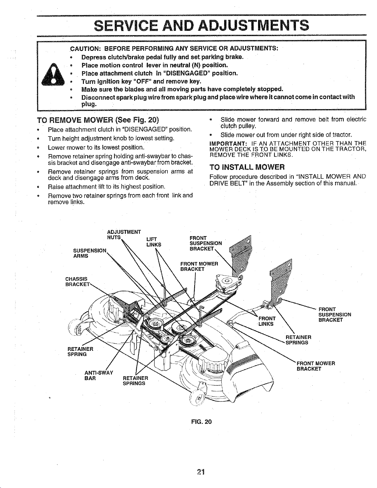
TO REMOVE MOWER (See Fig. 20)
Place attachment clutch in "DISENGAGED" position.
Turn height adjustment knob to lowest setting,
Lower mower to itslowest position_
= Remove retainer spring holdinganti-swaybar to chas-
sisbracket and disengage anti-swaybar from bracket,
• Remove retainer springs from suspension arms at
deck and disengage arms from deck.
, Raise attachment lift to its highest position.
Remove two retainer spnngs from each front link and
remove links.
• Slide mower forward and remove belt from electric
Clutchpulley,
• Slide mower out from under right side of tractor.
IMPORTANT: IF AN ATTACHMENT OTHER THAN THE
MOWER DECK IS TO BE MOUNTED ON THE TRACTOR,
REMOVE THE FRONT LINKS.
TO INSTALL MOWER
Follow procedure described in "INSTALL MOWER AND
DRIVE BELT" in the Assembly section of this manual.
ADJUSTMENT
NUTS
SUSPENSION
ARMS
CHASSIS
E
LIFT
LINKS
FRONT
SUSPENSION
BRACKET_
FRONT MOWER_
BRACKET
LINKS
FRONT
SUSPENSION
BRACKET
RETAfNER
SPRING
ANTI-SWAY
BAR RETAINER
SPRINGS
BRACKET
FIG. 20
2!
SERVICE ADJUSTMENTS
TO LEVEL MOWER HOUSING FRONT-TO-BACK ADJUSTMENT (See Figs. 23 and 24)
Adjust the mower while tractor isparked on leveeground or
driveway. Make sure tires are properly inflated (See
"PRODUCT SPECIFICATIONS" on page 3 of this manua!).
Iftires are over or underinflated, you will no1properly adjust
your mower.
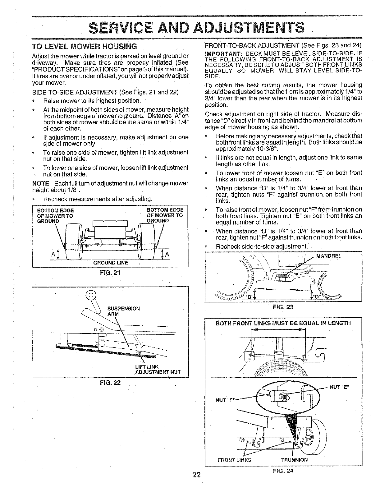
SIDE-TO-SIDE ADJUSTMENT [See Figs. 21 and 22)
Raise mower to its highest position.
At the midpoint of both sides of mower, measure height
from bottom edge of mower to ground. Distance"A" on
both sides of mower should be the same or within 1/4"
of each other.
if adjustment is necessarj, make adjustment on one
side of mower only.
To raise one side of mower, tighten lift link adjustment
nut on that side.
To lower one side of mower, loosen liftlink adjustment
nut on that side.
NOTE: Each full turn of adjustment nut will change mower
height about 1/8".
Resheck measurements after adjusting.
BOTTOM EDGE BOTTOM EDGE
OF MOWER TO OF MOWER TO
GROUND GROUND
GROUND LiNE
FIG. 21
IMPORTANT: DECK MUST BE LEVEL SIDE-TO-SIDE. IF
THE FOLLOWING FRONT-TO-BACK ADJUSTMENT IS
NECESSARY. BE SURETO ADJUSTBOTH FRONT LINKS
EQUALLY SO MOWER WILL STAY LEVEL SIDE-TO-
SIDE.
To obt_.in the best cutting results, the mower housing
should beadjusted sothat the front isapproximately 1/4" to
3/4" lower than the rear when the mower is in its highest
position,
Check adjustment on right side of tractor, Measure dis-
tance "D" directly in front and behind the mandrel at bottorr
eage of mower housing as shown.
Before making any necessary ad ustments checkthat
both front links are equal inlength. Both nks shou d be
approximately !0-3/8".
If links are not equal in length, adjust one link to same
length as other link.
To lower front of mower loosen nut "E" on both front
inks an equal number of turns.
When distance "D" is 1/4" to 3/4" lower at front than
rear, tighten nuts "F" against trunnion on both fronl
links,
re raise front of mower, loosen nut "F" from trunnion on
both front links. Tighten nut "E" on both fror: links an
equal number of turns,
When distance "D" is 1/4" to 3/4" lower at front than
rear. tighten nut"F"against trunnion on both front links,
Recheck side-to-side adjustment.
MANDREL
SUSPENSION
ARM
LiFT LiNK
ADJUSTMENT NUT
FiG. 22
FiG. 23
BOTH FRONT LINKS MUST BE EQUAL IN LENGTH
FRONT LINKS TRUNNION
NUT "E"
FIG 24
22
SERVICE ADJUSTMENTS
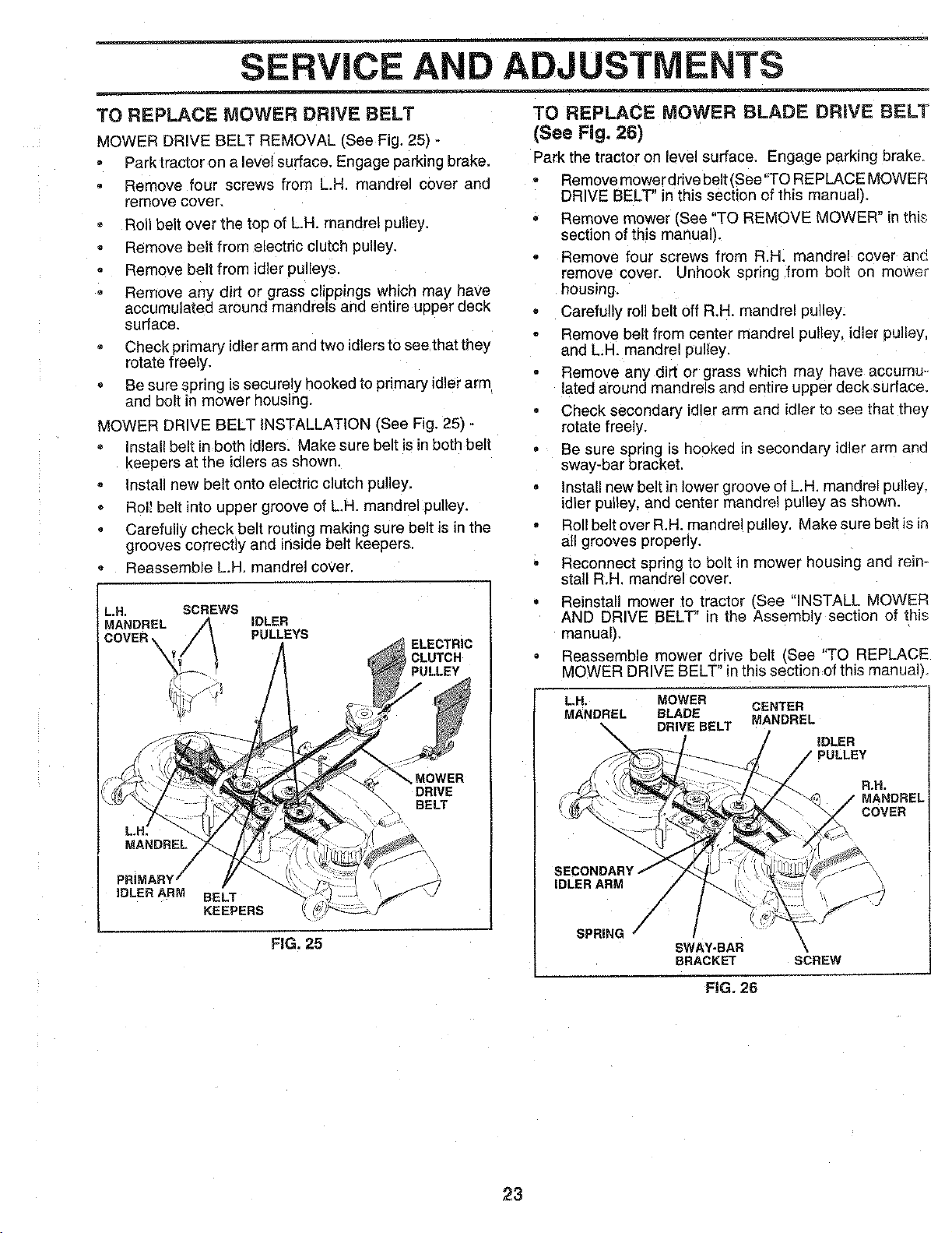
TO REPLACE MOWER DRIVE BELT
MOWER DRIVE BELT REMOVAL (See Fig, 25) -
Parktractor on a level surface. Engage parking brake,
Remove four screws From L,H, mandrel cover and
remove cover.
Roll belt over the top of L.H. mandrel pulley.
Remove belt from electric clutch pulley.
Remove belt from idler pulleys.
Remove any dirt or grass clippings which may have
accumulated around mandrels and entire upper deck
surface.
Check primary idlerarm and two idlers to see that they
rotate freely.
• Be sure spring is securely hooked to primary idler arm
and bolt in mower housing.
MOWER DRIVE BELT INSTALLATION (See Fig. 25) -
Install belt in both idlers. Make sure belt is in both belt
Keepers at the idlers as shown.
Install new belt onto electric dutch pulley.
Roll belt into upper groove of LH. mandrel pulley.
Carefully check belt routing making sure belt is in the
grooves correctly and inside belt keepers,
Reassemble L.H. mandrel cover,
L.H, SCREWS
MANDREL IDLER
COVER \ PULLEYS
ELECTRIC
CLUTCH
ILLEY
MOWER
DRIVE
BELT
FIG. 25
TO REPLACE MOWER BLADE DRIVE BELT
(See Fig. 26)
Park the tractor on level surface. Engage parking brake.
Remove mower drive belt (Bee"TO REPLACE MOWER
DRIVE BELT" in this section of this manual).
Remove mower (See "TO REMOVE MOWER" in thb
section of this manual).
Remove four screws from R,H. mandrel cover an_
remove cover. Unhook spring from bolt on mower
housing.
Carefu!ly roll belt off R.H. mandrel pulley.
Remove belt from center mandrel pulley, idler pulley,
and LH. mandrel pulley.
Remove any dirt or grass which may have accumu-.
lated around mandrels and entire upper deck surface.
Check seconaary idler arm and idler to see that they
rotate freely.
Be sure spnng is hooked in secondary idler arm ana
sway-bar bracket,
Install new belt in lower groove of LH. mandrel pulley
idler pulley, and center mandrel pulley as shown.
Roll belt over R.H. mandrel pulley, Make sure belt is in
all grooves properly.
Reconnect spring to bolt in mower housing and rein-
stall R.H, mandrel cover,
Reinstall mower to tractor _See "INSTALL MOWER
AND DRIVE BELT" in the Assembly section of this
manual).
° Reassemble mower drive belt _See "TO REPLACE
MOWER DRIVE BELT" in this section of this manuah
LH. _OWER
MANDREL BLADE
\ DRIVE
CENTER
MANDREL
iDLER
J PULLEY
R.N.
MANDREL
COVER
IDLER ARM
SPRING
SWAY-BAR
BRACKET
\
SCREW
FIG. 26
23
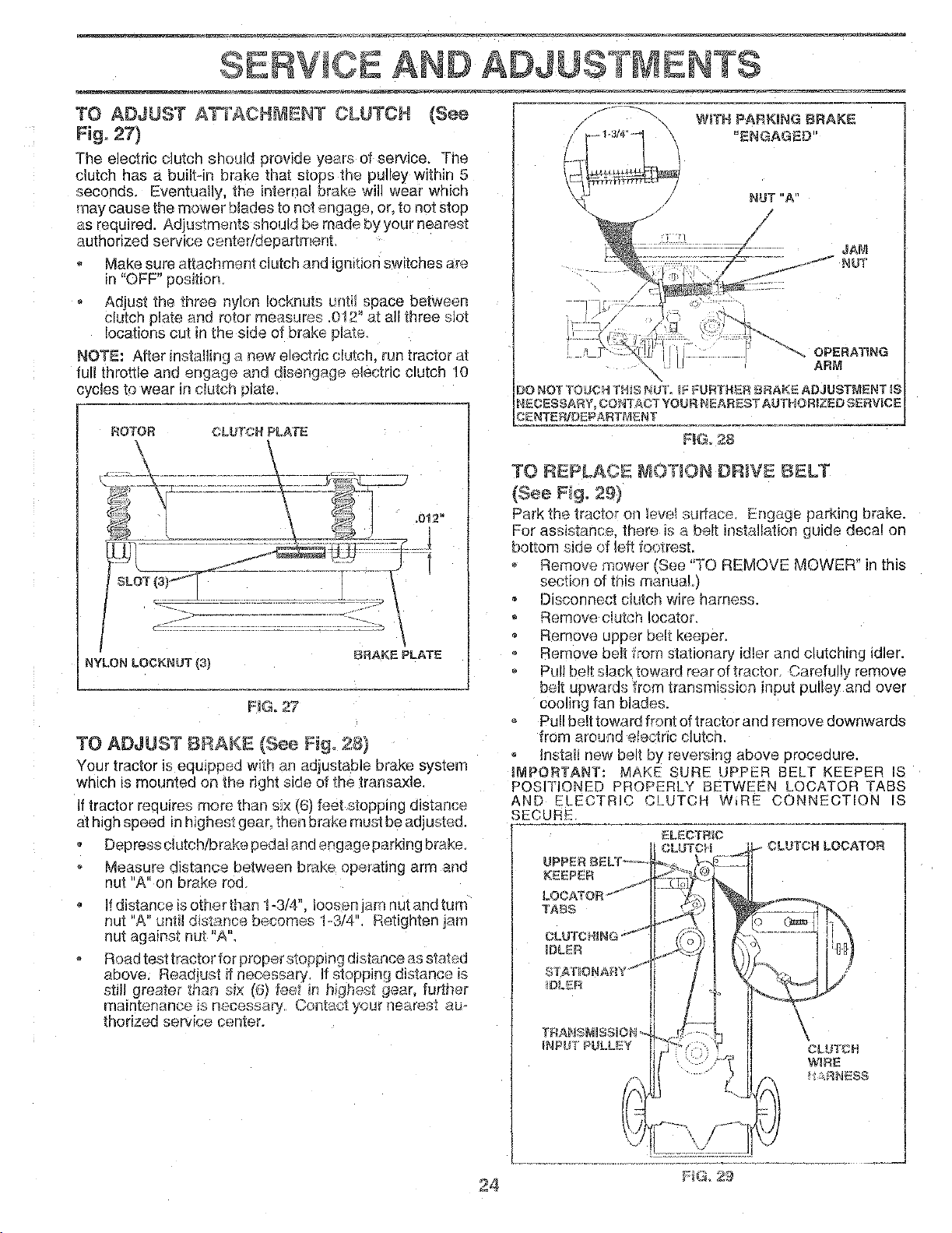
TO ADJUST ATTACHMENT CLUTCH (See
Fig, 27)
The electric clutch should provide year'.; of service, The
clutch has a bultAn brake that stops the pulley within 5
seconds. Eventually, the internal brake will wear which
may cause the mower blades to not engage, or, to not stoo
as required. Adius_ments should be made byyour nearest
authorizeo serwce oenteddepartmenl
SERVICE AND ADJUSTMENTS
," - WiTH PARKING BRAKE
'ENGAGEO"
Make sure attachment clutch and ignmon switches are
in "OFF" position
Adjust the three nylon ioeknuis unti space between
clutch plate and rotor measures .0!2" at all three slot
locations cut in the side of brake plate.
NOTE: After instaling a new electric clutch, run tractor at
full throttle and engage and disengage electric clutch 10
cycles to wear in clutch plate,
ROTOR CLUTCH PLATE
BRAKE PLATE
NG° 27
NYLON LOrKNUT{3)
TO ADJUST BRAKE (See Fig° 28)
Your tractor is equiPDed wth art adjustable brake system
which is mounted on the right side of the transaxle.
if tractor requires more than six (6) feet stopping distance
at high speed in highest gear. then brake must be adjusted.
Depress dutch/brake pedal and engage parking brake.
Measure distance between brake )perating arm and
nut "A" on brake rod
If distance is other than 1-3/4'L loosen am nut and turn
nut "A" until dist_nce becomes I-3/4". Refign_en jam
nut against nut "A'L
Road test tractor for proper stopping distance as stated
above Readlust if necessary, If stopping distance is
still greate, than sl_ (6) feet il hiqhest 9ear. further
maintenance _snecessaq,, Contact your nearest au-
thorized service cenLer.
NUT"A"
/
JAM
J,.,"J"_" NUT
24
OPERATING
ARM
\
)O NOT TOUCH THIS NUT. (__URTHER _RAKE ADJUSTMENT ((
NECESSAR% COr'_TA_T YOUR NEAREST AUTHORIZED SERV)CE
CENTERIDEPARTMENT
F_Go28
TO REPLACE _IOTgON DR)VE BELT
(See Fig. 29)
Park the tractor on lew_l surface Engage parking brake.
For assist _nce. there is a belt instalation guide decal on
bottom side ef left footrest.
Remove mower ISee "TO REMOVE MOWER" in this
section of this manual.)
Disconnect clutch wire harness.
Remove c!utoh lecator.
Remove upper belt Keeper.
Remove belt from stationary idler and clutching idler.
Pull be!t slack toward rear of tractor. Carefully remove
belt upwards from transmission input pulley ana over
cooling fan blades.
Pull belt toward front of tractor and remove downwards
from around electnc clutch.
Install new belt by reversing above proceaure
iMPORTANT: MAKE SURE UPPF_R 3ELT KEEPER IS
POSITIONED PROPERLY BETWEEN LOOATQR TABS
AND ELECTRIC CLUTCH W,RE CONNECTION IS
SECURE
UPPER B_:"LY_-_-
TAeS
CLUTCHING "_'_
3DLER
IDL[:R
TRANSNISSION o-
INPU[ F ULLEY
ELECTRIC
CLUTCH
]-V/:::?
1"
LUTOR LOCATOR
l....ii:4
CLU_CN
WIRE
I__NESS
FIG, 29
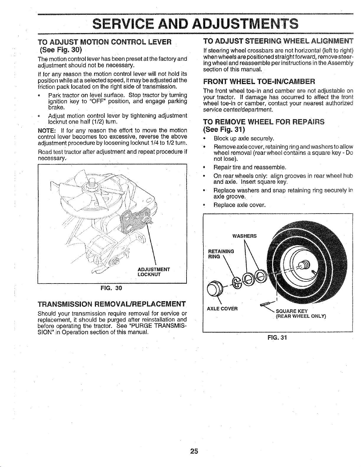
SERVICE AND ADJUSTMENTS
TO ADJUST MOTION CONTROL LEVER
(See Fig, 30)
The motion control lever has been oreset atthe factory and
adjustment should not be necessary.
If for any reason the motion control lever will not hold its
positionwhileat a selected speed, itmay beadjusted at the
ffictio_ pack located on the right side of transmission.
Park tractor on level surface, Stop tractor by turning
ignition key to "OFF position, and engage parking
brake.
Adjust motion control lever by tightening adjustment
Iocknut one half (1/2) turn.
NOTE: If for any reason the effort to move the motion
control lever becomes too excessive, reverse the above
adjustment procedure by loosening Iocknut 1/4to 1/2 turn.
Road test tractor after adjustment and repeat procedure if
necessary.
\
/
/
ADJUSTMENT
_J_-J LOCKNUT
FIG. 30
TRANSMISSION REMOVAL/REPLACEMENT
Should your [ransm_ssJon require removal for service or
replacement, it should be purged after reinstallation and
before operating the tractor. See "PURGE TRANSMiS-
SiON" in Ooeration section of this manual.
TO ADJUST STEERING WHEEL ALIGNMENT
If steering wheel crossbars are not horizontal (left to right)
when wheels are positioned straight forwara, remove steer-
mgwheel and reassemble per instructions in the Assembly
section of this manual.
FRONT WHEEL TOE-IN/CAMBER
The front wheel toe-in and camber are not adjustable on
your tractor, if damage has occurree to affect the front
wheel toe-in or camber, contact your nearest authorized
service center/department.
TO REMOVE WHEEL FOR REPAIRS
(See Fig. 31)
, Block up axle securely.
Remove axle cover, retaining ring aria washersto allow
wheel removal (rear wheel contains a square Key - Do
not lose).
• Repair tire and reassemble.
On rear wheels only: align grooves in rear wheel hub
and axle. Insert square key.
Replace washers and snap retaining ring securely i_
axle groove.
Replace axle cover.
WASHERS
RETAINING
RiNG
AXLE COVER
I
_SGUARE KEY
(REAR WHEEL ONLY)
RG. 31
25
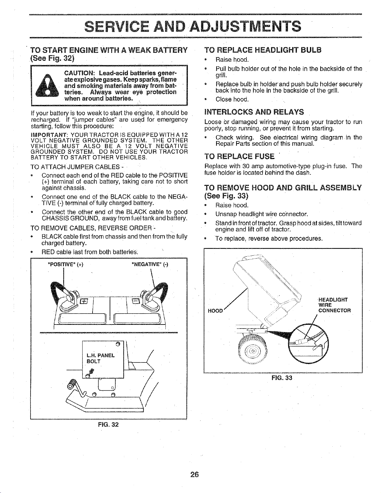
D ADJUSTMENTS
TO START ENGINE WiTH A WEAK BATTERY
See Fig. 32)
CAUTION: Lead-acid batteries gener-
ate e×plosive gases. Keep sparks, flame
and smoking materials away from bat-
terieso Always wear eye protection
when around batteries.
If your battery is toc weak to start the engine, it should be
recharged. If "jumper cables" are usec for emergency
starting, follow this procedure:
iMPORTANT: YOUR TRACTOR IS EQUIPPED WITH A 12
VOLT NEGATIVE GROUNDED SYSTEM. THE OTHER
VEHICLE MUST ALSO BE A 12 VOLT NEGATIVE
GROUNDED SYSTEM. DO NOT USE YOUR TRACTOR
BATTERY TO START OTHER VEHICLES.
TO ATTACH JUMPER CABLES -
Connect each end of the RED cable to the POSITIVE
(+_ terminal of each battery, taking care not to short
against chassis.
Connect one ena of the BLACK cable to the NEGA-
TIVE (-) terminal of fully charged battery.
Connect the other end of the BLACK cable to gooc
CHASSIS GROUND. away from fueltankand battery.
TO REMOVE CABLES. REVERSE ORDER-
BLACK cable first from chassis and then from the fully
charged battery.
RED cable last from both battenes.
"POSiTiVE" (+) "NEGATIVE" (-)
LH. PANEL _ I/ /
BOLT
TO REPLACE HEADLIGHT BULB
Raise hood.
Pull bulb holder out of the hole in the backside of the
grill.
Replace bulb in holder and push bulb holder securely
back into the hole in the backside of the gdll.
C!ose hood.
iNTERLOCKS AND RELAYS
Loose or damaged wiring may cause your tractor to run
poorly, stop running, or preven[ itfrom starting.
Check wiring. See electrical wiring diagram in the
Repair Parts section of this manual.
TO REPLACE FUSE
Replace with 30 amp automotive-type plug-in fuse. The
fuse holder is located behind the dash.
TO REMOVE HOOD AND GRILL ASSEMBLY
(See Fig. 33)
Raise hood
= Unsnap headlight wire connector.
Standinfrontoftracter. Grasphoedatsides tiittoward
engine and lift off of tractor.
To replace, reverse above procedures.
HOOD
/
/ -_,_ HEADLIGHT
WIRE
/ CONNECTOR
FIG. 33
FiG. 32
26

SERVICE AND ADJUSTMENTS
ENGINE
TO ADJUST THROTTLE CONTROL CABLE
(See Fig. 34)
The throttle control has been preset at the factory and
adjustment should not be necessary. Check adjustment as
described below before loosening cable. If adjustment is
necessary, proceed as follows:
With engine not running, move throttle control lever
from slow (_) to choke (1\1) position. Slowly move
lever from choke (l\l) to fast (4) position.
Check to see if hole in throttle lever and hole in speed
control bracket are aligned.
If holes are not aligned, oosen cable clamp screw and
align the holes by inserting a pencil or a 1/4' drill bit
through both holes.
Pull throttle cable up to remove slack and tighten cable
clamp screw. Remove alignment pencil or ddl! bit.
TO ADJUST CARBURETOR (See Fig. 35)
The carburetor has been preset at the factory and adjust-
ment. should not be necessary. However. minor adjust-
ment may be required to compensate for differences in fuel.
temcerature, altitude or load. Ifthe carburetor does need
adjustment, oroceed as follows:
In general, turning the adjusting needles in (clockwise)
decreases the supply of fuel to the engine giving a leaner
fuel/air mixture. Turning the adjusting needles out (counter-
clockwise) increases the supply of fuel to the engine gMng
a richer fuel/air mixture.
IMPORTANT: DAMAGE TO THE NEEDLES AND THE
SEATS N CARBURETOR MAY RESULT IF NEEDLE IS
TURNED IN TOO TIGHT.
NOTE: The carburetor on this engine is low emission, tt is
equipped with an idle fuel adjusting needle with a limiter
cap,which allows some adjustment within the limits allowed
by the cap. Do not attempt to remove the limiter cap. The
limitercap cannot be removedwithout breaking the adjusting
needle.
Be sure you have a clean air filter and the throttle
control cable is adjusted properly (see aoovel.
Start engine and allow to warm for five minutes. Make
ad ustments with engine running and shift/motion control
ever n neutra N) postion.
Idle speed setting - With throttle control lever in slow
(-=_,) position, engine should idle at 1750 RPM. If
engine idles too slow or fast, turn idle speed adjusting
screw in or out until correct idle is attained.
[die fuel needle settinq - With throttle control lever in
slow (,_) position, turn idle fuel adjustment needle in
(clockwise) until engine begins tc die and then turn out
(counterclockwise) until engine runs rough. Turn needle
to a point midway between those two positions.
Recheck idle speed. Readjust if necessary.
ACCELERATION TEST -
• Move throttle control lever from slow (._) to fast (,,_)
position. If engine hesitates or dies, turn idle fuel
adjusting needle out (counterclockwise) 1/8 turn. Re-
peat test and continue to adjust, if necessary, until
engine accelerates smoothly.
High speed stop is factory adjusted. Do not adjust .-
damage may result.
IMPORTANT: NEVER TAMPER WITH THE ENGINE
GOVERNOR, WHICH IS FACTORY SET FOR PROPE[_
ENGINE SPEED. OVERSPEEDINGTHE ENGINEABOV[
THE FACTORY HIGH SPEED SETTING CAN B_
DANGEROUS. IF YOU THINK THE ENGINE-GOVERNE;)
HIGH SPEED NEEDS ADJUSTING CONTACT YOUR
NEAREST AUTHORIZED SERVICE CENTER/
DEPARTMENT WHICH HAS PROPER ECUIPMENTAND
EXPERIENCE TO MAKE ANY NECESSARY
ADJUSTMENTS.
CARLE ,-_
CLAMP
SCREW_
SPEED CONTROL"_.-,,..,..,_
BRACKET
THROTTLE
LEVER
F_G. 34
IDLE SPEED
ADJUSTING
IDLE FUEL /
ADJUSTING
NEEDLE
FIG. 35
27
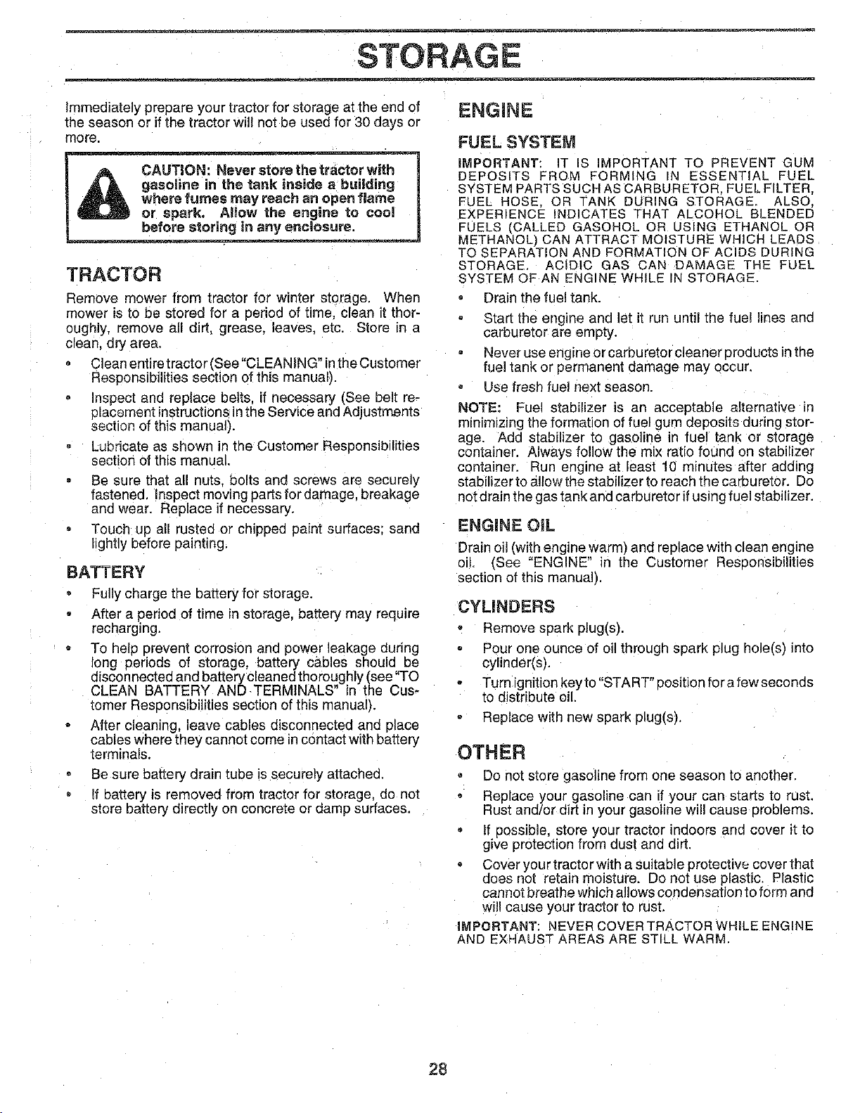
STORAGE
Immediately prepare your tractor for storage at the end of
the season or if the tractor will not be used for 30 days or
more.
CAUTION: Never store the tractor with
gasoline in the tank inside a building
where fumes may reach an open flame
or spark. Allow the engine to cool
before storing in any encgosure.
TRACTOR
Remove mower from tractor for winter storage. When
mower is to be stored for a period of time, clean it thor-
oughly, remove ell dirt, grease, leaves, etc. Store in a
clean, dry area.
Clean entire tractor (See "CLEANING" in the Customer
Responsibilities section of this manual).
Inspect and replace belts, if necessary (See belt re-
placement instructions in the Service and Adjustments
section of this manual).
Lubricate as shown in the Customer Responsibilities
section of this manual.
Be sure that all nuts. bolts and screws are securely
fastened, inspect moving parts for damage, breakage
and wear, Replace if necessary.
Touch up all rusted or chipped paint surfaces: sand
lightly before painting.
BATTERY
Fully charge the battery for storage,
After a period of time in storage, battery may require
recharging.
To help prevent corrosion and power leakage during
long periods of storage, battery cables should be
disconnected and battery cleaned thoroughly (see "TO
CLEAN BATTERY AND TERMINALS in the Cus-
tomer Resoonsibilities section of this manualL
After cleaning, leave cables disconnected and place
cables where they cannot come in contact with battery
terminals.
Be sure battery drain tube is securely attached.
If battery is removed from tractor for storage, do not
store battery directly on concrete or damp surfaces,
ENGINE
FUEL SYSTEM
IMPORTANT: IT iS iMPORTANT TO PREVENT GUM
DEPOSITS FROM FORMING IN ESSENTIAL FUEL
SYSTEM PARTS SUCH AS CARBURETOR FUEL FILTER.
FUEL HOSE. OR TANK DURING STORAGE. ALSO.
EXPERIENCE iNDICATES THAT ALCOHOL BLENDED
FUELS _CALLED GASOHOL OR USING ETHANOL OR
METHANOL') CAN ATTRACT MOISTURE WHICH LEADS
TO SEPARATION AND FORMATION OF ACIDS DURING
STORAGE, ACIDIC GAS CAN DAMAGE THE FUEL
SYSTEM OF AN ENGINE WHILE iN STORAGE
Drain the fuel tanK.
Start the engine and let it run until the fuel lines ane
carburetor are empty.
Never use engine or carburetor cleaner products in the
fuel tank or permanent damage may occur.
Use fresh fuel next season.
NOTE: Fuel stabilizer is an acceptable alternative in
mintm_zrng the formation of fuel gum deposits during stor-
age. Add stabilizer to gasoline in fuel tank or storage
contalner. Always follow the mix ratio found on stabilizer
container. Run engine at least 10 minutes after adding
stabilizertoaltowthestabilizert_ reachthecareureter. 30
not drain the gas tank and carburetor if using fuel stabilizer.
ENGINE OiL
Drain oil (with engine warm) and replace with clean engine
ell, (See "ENGINE" in [he Customer Reseonsibilities
section of this manual).
CYLINDERS
= Remove spark plug(s).
Pour one ounce of oil through spark plug hole(s) into
cylinder(s),
Turn ignition key to "START" eosition for a few seconds
to distribute oil,
Replace with new spark plug(s),
OTHER
Do not store gasoline from one season to another.
Replace your gasoline can if your can starts to rust.
Rust and/or dirt in your gasoline will cause problems.
If possible, store your tractor indoors and cover it to
give protection from dust and dirt.
Cover you r tractor with a suitable protective cover that
does nol retain moisture. Do not use plastic. Plastic
cannot breathe which allows condensation to form and
will cause your tractor to rust,
IMPORTANT: NEVER COVER TRACTOR WHILE ENGINE
AND EXHAUST AREAS ARE STILL WARM.
28
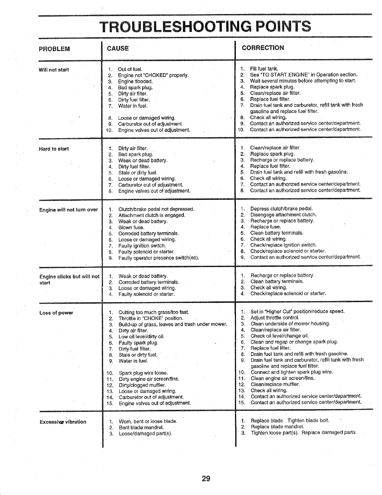
TROUBLESHOOTING POINTS
PROBLEM
Will not start
Hard to start
Engine will not turn over
Engine clicks but will no!
start
Loss of power
Exceseiv_ vibration
CAUSE
1 Out of rue
2 Engine not "CHOKED" properly.
3 Engine flooded.
4_ 3ad spark plug.
5. Dirty air filter.
6. Dirty fuel filter
7. Waterin fuel,
8. Loose or aamaged widng.
9. Carburetor out of adjustment.
10, Engine valves out of adjustment,
1. Dirty air filter,
2 Bad spark plug.
3 Weak or dead battery.
,1 Dirty fuel filter.
5. Stale or dirty fuel.
6 Loose or damaged wiring.
7 Carburetor out of adlustment.
8 Engine valves out of adjustment.
1 C]utchrbrake pedal not deeressea.
2. Attachment clutch is engaged,
3. Weak or dead battery.
4. B_own fuse.
5, Corroded batterymrminals
6, LOOSeor aamaged wiring,
7. Faulty tgnition switch.
8. Faulty solenoid or starter.
9. Faulty operator presence switch_es).
1. Weak or dead battery.
2. Corroded battery terminals.
3. Loose or damaged wiring,
4. Faulty solenoid or starter.
I. Cutting too much grass/too fast.
2. Throttle in "CHOKE" position
3, Build-no of grass, eaves and trash under mower,
4, Dirty air filter,
5, LOWoil level/dirty oil
6, Faulty spark plug.
7, Dirty fue! filter,
8, Stale or dirt,/fuel.
9. Water in fuel.
10. Spark plug w_reloose.
11 Dirty engine air screen/fins
12. Dirty/clogged muffler.
13. Loose or darnageo wrong.
t4. Carburetor out of adjustment.
15. Engine valves out of adiustment.
t. Worn Dent or loose blade.
2, Bent blad_ mandrel
3. Loose/oamageo part(s).
CORRECTION
1. Fill fuel tank.
2. See 'q-O START ENGINE" in Operation section.
3. Wait several minutes before attempting to start,
4. Replace spark plug.
5. Clean/replace air filter.
6. Replace fuel filter
7, Drain fuel tank and carburetor, refill tank with fresh
gasoline and replace fuel filter,
3. Check all widng.
9. Contact an authorized service center/ueDanmenr.
10. Contact an authorized service cen[er/GeDartmen_,
1. Clean/replace air filter.
2. Reolace spark plug.
3. Recharge or replace battery.
4, Replace fuel filter
5, Drain fuel tank and refill with fresh gasoline
6, Check all widng.
7, Contact an authorized service center/department
8, Contact an authodzed service center/department.
t, Depress clutch/brake oedal,
2, Disengage attachment clutch.
3. Recharge or rep ace battery,
4. Replace fuse,
5. Clean battery terminals.
6, Checkall wiring
7, Checldreolace ignition swttci_.
8. Check/reelace solenoid or starter,
9. Contact an authorized service center/department
t, Recharge or replace battery.
2. Clean battery terminals.
3, Check all wiring.
CheckJreplace solenoid or starter.
f. Set in "Higher Cur position/reduce soeed.
2. Adjust throttle control.
3, Clean underside of mower housing.
4. Clean/replace air filter.
5. Check oil level/change otl,
6. Clean and regap or change spark plug.
7. Reelace fuel fi!fer
8, Drain fuel tank and refill with fresh gasoline.
9. Drain fuel tank and carburetor, refill tank with fresh
gasoline and reptace fuel filter,
10. Connect and t_gmen soark plug wire.
11 Clean engine air screen/fins.
12. Olean/re[_Lace muffler
13. Check all wiring.
t4. Contact an authorized service center/department.
15. Contact an authorized servtce eenter/deoartment.
1 Replace blade. Tighten blade bolt.
2 RepLace blade mandrel
3 Tighten loose part(s). Replace damaged pans.
29
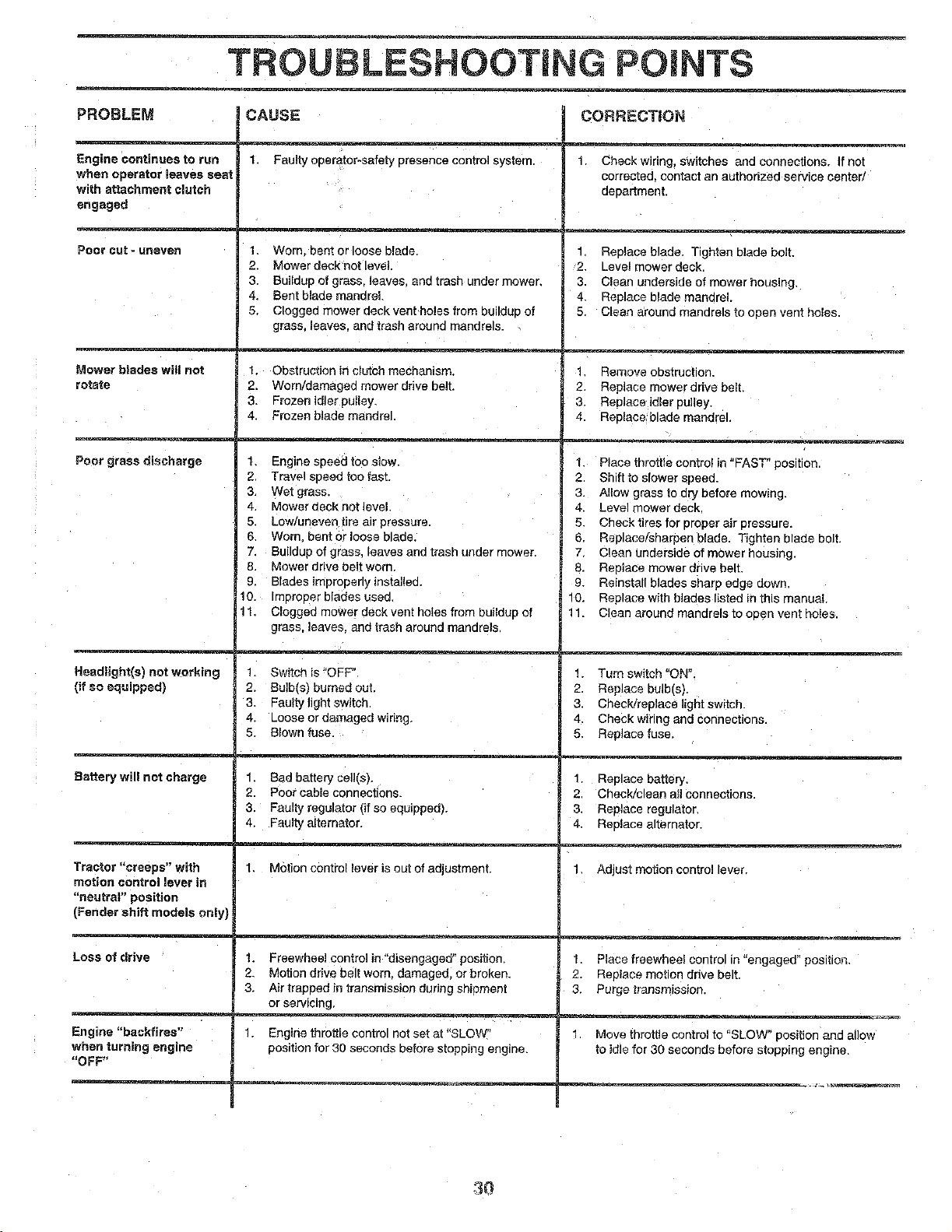
TROUBLESHOOTING POINTS
PROBLEM
Engine continues to ran
when operator leaves seat
with attachment clutch
engaged
Poorcut-uneven
Mower blades will not
rotate
Poor grass dl,_¢harge
Headlight(s] not working
(if so equipped)
Battery will not charge
Tractor "creeps" with
motion control lever m
"neutral" position
(Fender shift models only)
Loss of drive
Engine "backfires"
when turning engine
"OFF"
CAUSE
t. Fautty operator-safety presence control system.
1. Worn. eem or loose b!ade
2. Mower deck not level
3. Buildup of grass, leaves, and trash under mower.
4. Bent blade mandrel
5. Clogged mower deck vent holes from buildup of
grass, leaves, and trash around mandrels
1. Obstruction in clutch mechanism
2. Worn/damaged mower drive belt
3. Frozen idler pulley,
4 Frozen blade mandrel.
1 Engine speed too slow.
2 Travel speed too fast.
3. Wet grass.
4 Mower deck not level.
5. Low/unever tire air oressure.
6. Worn bent or loose blade.
7. Buildup of grass, leaves and trash unaer mower
8. Mower drive behworn.
9. Blades imDrooenyinstalled.
10. ImDroDer blades used
lt. Clogged mower deck vent holes from buildup of
grass, leaves and trash around mandrels
1. Switch is "OFF".
2. Bu]bfs) r_umed out.
3. Faulty lignt switch
4. Loose or damaged wiring.
5. Blown fuse.
1. Bad battery cel!(s).
2. Poor cable connections.
3. Faulty regulator {if so equ=pped).
4. Faulty alternator.
1_ Motion control lever is out of adjustment.
1. Freewheel centre] in "disengaged" pos=tion.
2. Motion drive belt worn. damaged, or broken.
3. Air trapped in transmission during shipment
or servicing.
1. Engine throttle control not set at"SLOW"
position for 30 seconds before stopping engine
CORRECTION
3. Check wiring, switches and connections. If not
corrected contact an authorized service center/
aena_tment.
1 Replace blade. Tighten blade bolt.
2. Level mower deck.
3. Clean underside of mower housing.
4. Replace blade mandrel
5 Clean around mandrels to open vent holes
] Remove obstruction
2 Replace mower drive belt.
3. Replace idler pulley.
4. Reelace blade mandrel.
1. Place throttle contro! in "FAST" posltlor
2 Shift to slower sDeed.
3. Allow grass to dry before mowing.
4_ Level mower deck
5. Check tires for proper a=rpressure.
6. Replace/shah)an blade. Tighten blade bolt.
7 Clean underside of mower housing.
8 Replace mower _rive belt.
9 Reinstall blades sharp edge sown.
10 Replace with blades listed in this manual
11 Clean around mandrels to eden vent holes.
! Turn switch "ON".
2. Replace bulb(s).
3. Check/reolace light switcl
4. Check wiring and connections.
5. Replace fuse
1. Reelace battery.
2. Check/clean aJlconnections.
3. RepJace reguJator.
4. ReDlace alternator.
1 Adjust motion controllever.
t. Place freewheel control _n"engaged" position,
2. Replace motion drive belt.
3. Purge [ransm_ssion.
Move throttle control to "SLOW" position and allow
to idle for 30 seconds before stopping engine.
30
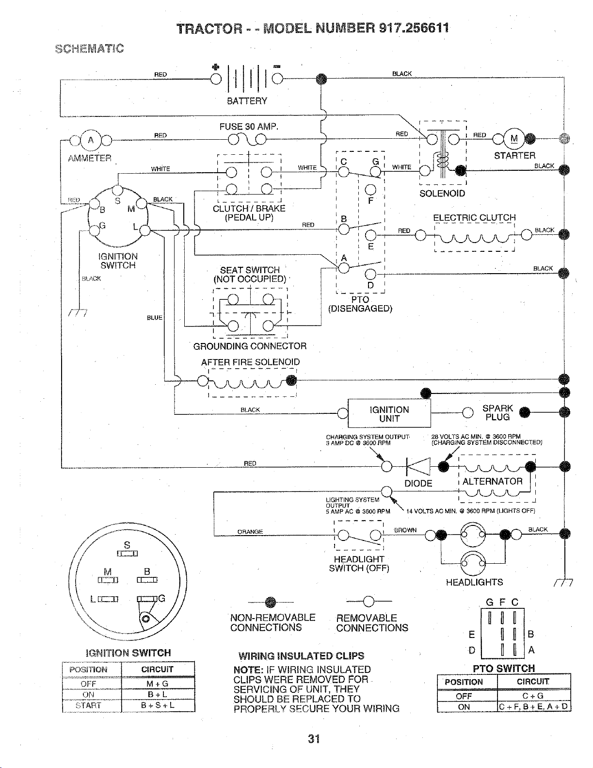
TRACTOR o- MODEL NUMBER 917.256611
AMMETER
RED
RED
WHITE
BLUE
÷11°
o111o----
BATTERY
(_L-U_'CH/ BRAKE
(PEDAL UP)
RED
SEAT SWITCH
(NOT OCCUPIED]
I I
I
GROUNDING CONNECTOR
AFTER FIRE SOLENOID
BLACK
\
[C G I! _ ; STARTER [
.__1 I WHITE =_ BLACK 0
...... J
O SOLENOID
F
ELECTRIC CLUTCH
E L-_ J I
/
D
PTO
(DISENGAGED}
!
BLACK
I-o
C_ IGNITION SPARK _.___UNIT PLUG
RED
CHARGING SYSTEM OUTPUT 28 VOLTS AC MIN. @ 3600 RPM
3 AMP DC @ 3600 RPM tCHARGING SYSTEM DISCONNECTED'
I- -
LIGHTING SYSTEM j
OUTPUT EM _,
ORANGE
5AMPAC @ 360[ RPM
HEADLIGHT
SWITCH (OFF)
"% 14 VOLTS AC MtN. @ 3SOS RPM [LIGHTS OFF
BROWN
HEADLIGHTS
_GH_TION SWITCH
OFP
ON
S[ART
POSITION CIRCUIT
M*G
B+L
B+S+L
@
NON-REMOVABLE
CONNECTIONS
O
REMOVABLE
CONNECTIONS
WiRiNG INSULATED CUPS
NOTE: IF WIRING INSULATED
CLIPS WERE REMOVED FOR
SERVICING OF UNIT, THEY
SHOULD BE REPLACED TO
PROPERLY SECURE YOUR WIRING
GFC
E _ _ B
D B _ A
PTO SWITCH
POSITION CIRCUIT
OFF C + G
ON C+F,B+E.A+D
31
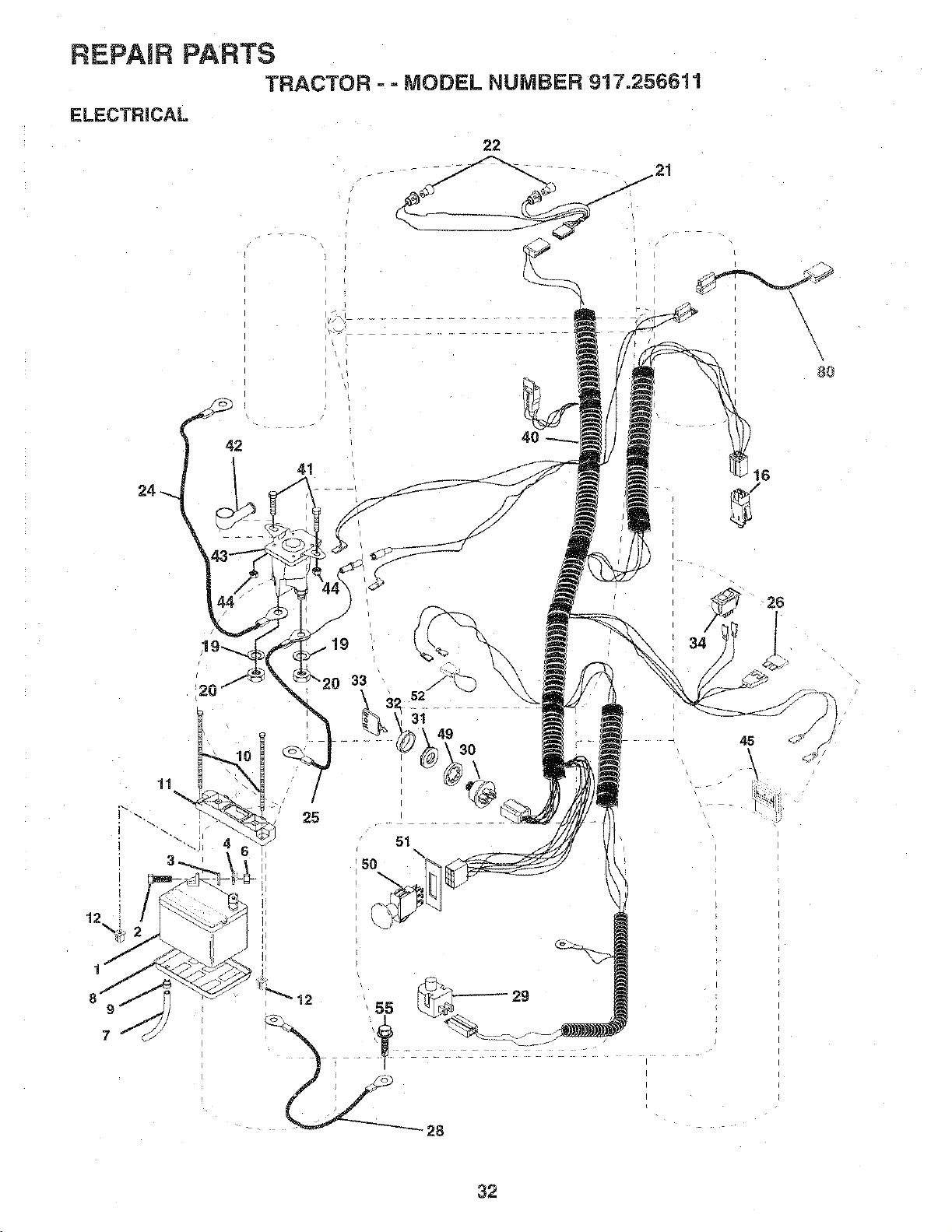
REPAIR PARTS
TRACTOR ==MODEL NUMBER 917.256611
ELECTRICAL
22
42
41
16
• /
1
7
20
11
25
12
51
50
45
\
29
32

REPAIR PARTS
TRACTOR =- MODEL NUMBER 917.256611
ELECTRICAL
KEY PART
NO, NO. DESCRIPT_ON
1 146140 Battery
2 74760412 Bolt. Hex 1/4-20 UNC x 3/4
3 STD551025 Washer
4 STD551125 Washer
6 STD541025 Nut
7 7697J Tube. Plastic
8 7603J Tray, Battery
9 109596X Clamo. Hose
10 145211 Bolt, Btr. Fri 1/4-20 x 7.5
11 145209 Holddown Btr. Dash
12 145769 Nut. Push Nylon 1/4" Battery
16 153664 Switch Intelock Push-In
19 STD551125 Washer, Lock
20 73350400 Nut. Hex. Jam 1/4-20 UNC
21 136850 Harness. Light Socket W/4152J
22 4152J Bulb. Light
24 146136 Cable Battery
25 146148 Cable. Battery
26 108824X Fuse
28 145491 Cable. Ground
29 121305X Switch. Plunger
30 144921 Switch. Ignition
3! 140400 Nut. Ignition
32 141226 Cover. Ignition Switch
33 140403 Key, !£qition
34 110712X Switch. Light
40 149170 Harness ignition
41 71110408 Bolt BIk Fin. Hex 1/4-20 x 3/4
42 131563 Cover, Terminal
43 145673 Solenoid
44 73640400 Nut. Lock W/Ins. 1/4-20
45 121433X Ammeter Rectangular 16Amo
49 |53249 Washer Pinned Delta
50 146283 Switch PTO 3 Pot Red Delta
51 140405 Ring Retainer PTO
52 141940 Wire Loop
55 17490508 Screw Thdrol 5/16-18 x 1/2 TYT
80 146685 Harness Clutch EVX
NOTE: All component dimensions given in U.S. inches
1 inch = 25.4 mm
33
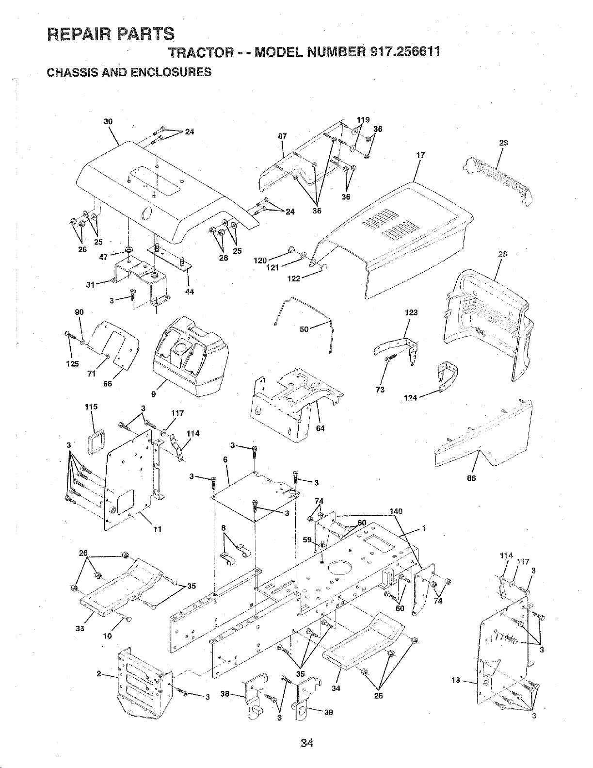
REPAIR PARTS
TRACTOR - - MODEL NUMBER 917.256611
CHASSIS AND ENCLOSURES
26
125
71
9O
115
/
/
66
25
26
121
44
\
11
117
/
114
/
36
36
86
26
33
/
I0
35
26
/
114
34
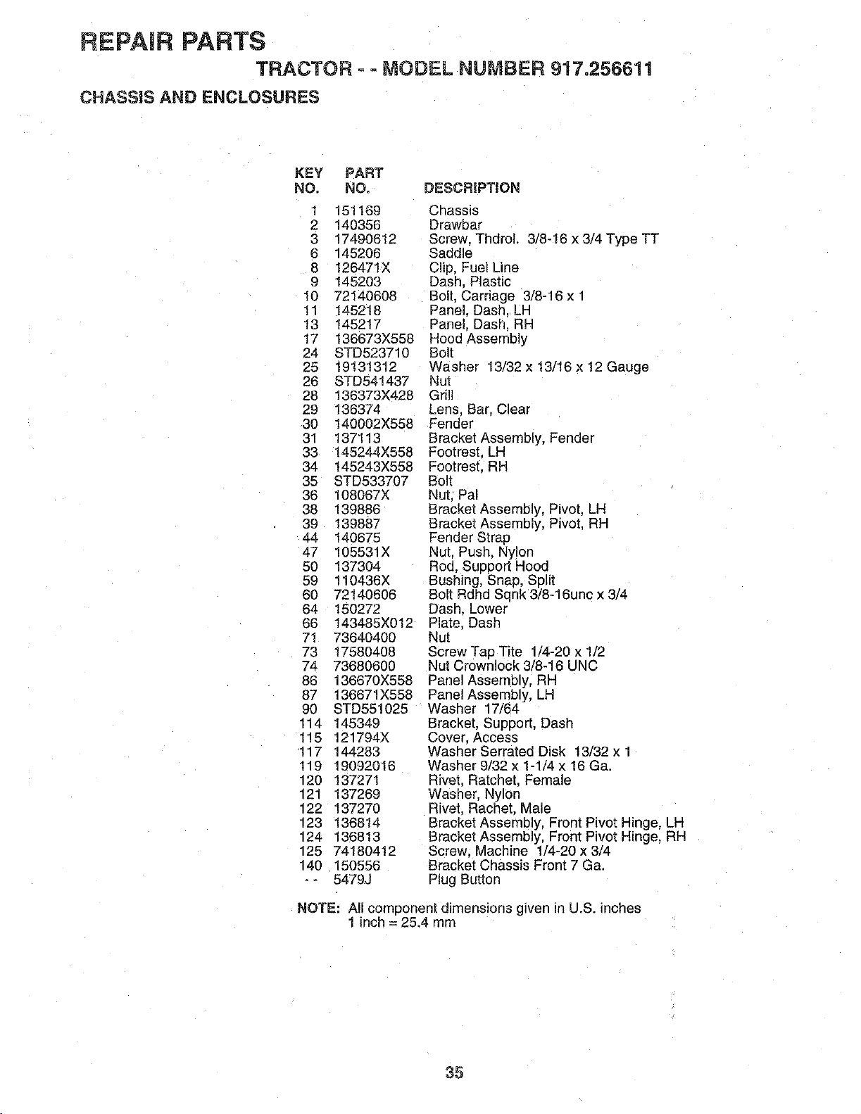
REPAIR PARTS
TRACTOR o=MODEL NUMBER 917.256611
CHASSIS AND ENCLOSURES
KEY PART
NO. NO, DESCRIPTION
1 151169 Chassis
2 140356 Drawbar
3 17490612 Screw. ThdroL 3/8-16 x 3/4 Type TT
6 145206 Saddle
8 126471X Clip, Fuel Line
9 145203 Dash. Plastic
10 72140608 Bolt. Carriage 3/8-16 x 1
11 145218 Panel. Dash. LH
13 145217 Panel. Dash. RH
17 136673X558 Hood Assembly
24 STD523710 Bolt
25 19131312 Washer 13/32 x 13/16 x 12 Gauge
26 STD541437 Nut
28 136373X428 Grill
29 136374 Lens. Bar. Clear
30 140002X558 Fender
31 137113 Bracket Assembly, Fender
33 145244X558 Footrest. LR
34 145243X558 Footrest. RH
35 STD533707 Bolt
36 108067X Nut. Pal
38 139886 Bracket Assembly, Pivot, LH
39 139887 Bracket Assembly. Pivot. RH
44 140675 Fender Strap
47 105531X Nut. Push. Nylon
50 137304 Rod, Suoport Hood
59 110436X Bushing, Snap, Split
60 72140606 Bolt Rdhd Sqnk 3/8-18unc x 3/4
64 150272 Dash. Lower
66 t43485X012 Plate. DasP
71 73640400 Nut
73 17580408 Screw Tap Tite 1/4-20 x 1/2
74 73680600 Nut Crownlock 3/8-16 UNC
86 136670X558 Panel Assembly, RH
87 136671X558 PanelAssembly, LH
90 STD551025 Washer 17/64
114 145349 Bracket. Support. Dash
115 121794X Cover. Access
117 144283 Washer Serrated Disk 13/32 x 1
119 19092016 Washer 9/32 x 1-1/4 x 16 Ga.
120 13727! Rivet. Ratchet. Female
121 137269 Washer. Nylon
122 137270 Rivet. Rachet. Male
123 136814 Bracket Assembly, Front Pivot Hinge, LH
124 136813 Bracket Assembly, Front Pivot Hinge, RH
125 74180412 Screw. Machine 1/4-20 x 3/4
140 150556 Bracket Chassis Front 7 Ga.
-- 5479J Plug Button
NOTE: All component dimensions given in U.S. inches
1 inch = 25.4 mrrl
35
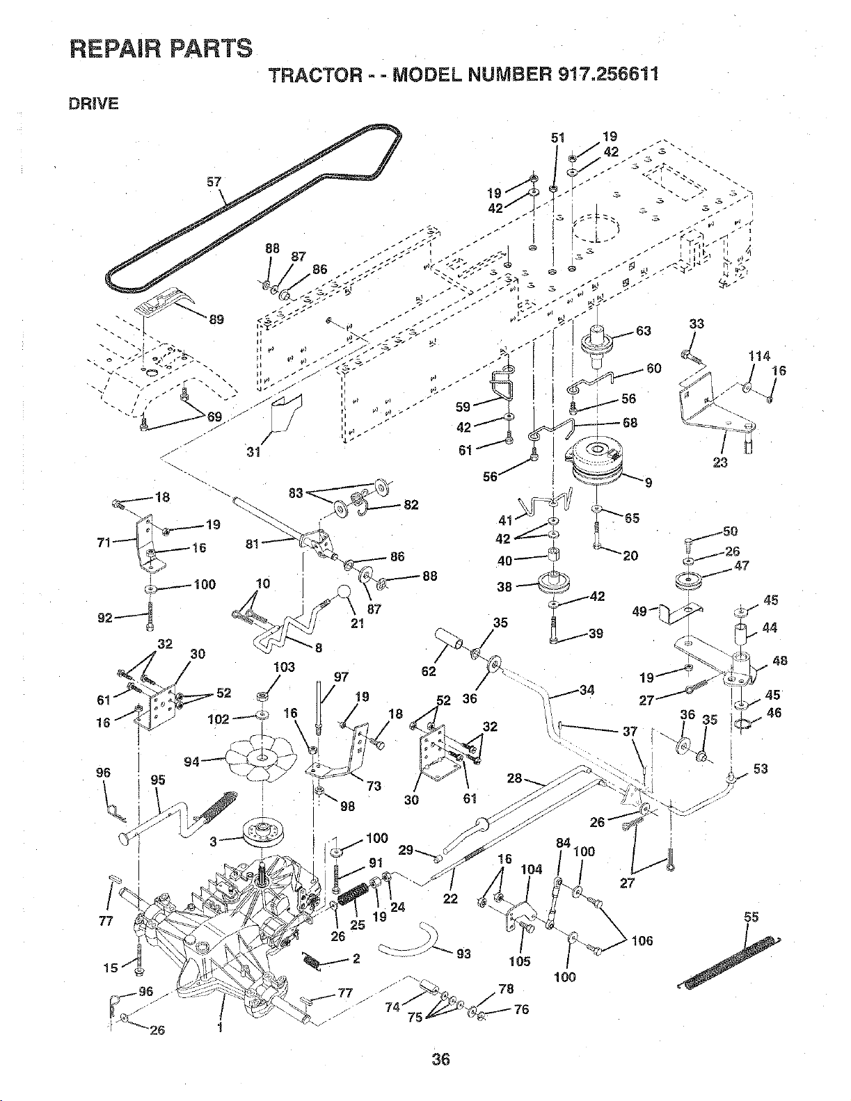
REPAIR PARTS
TRACTOR - - MODEL NUMBER 917.256611
DRIVE
57
_y
q
I
10
87
21
61
16
97 62
/ _9 -=;2 36
•73
"'- 30 61
98
27
53
36
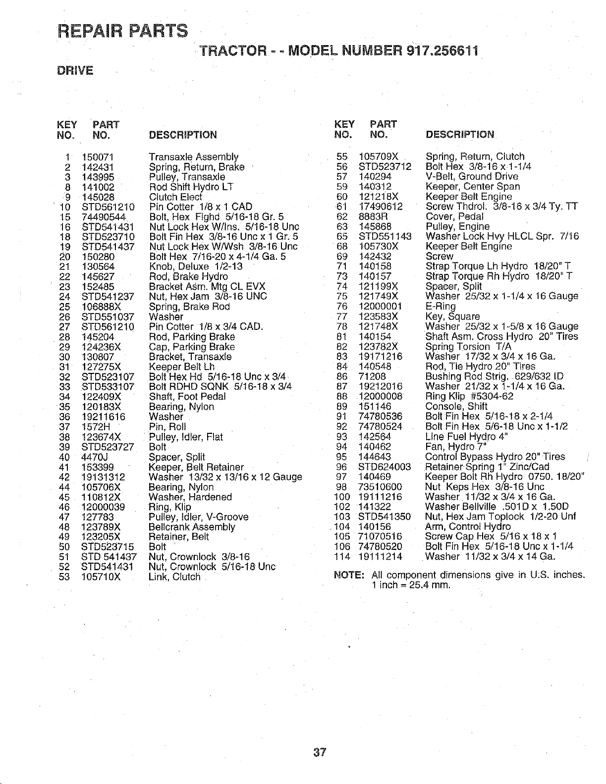
REPAIR PARTS
TRACTOR =- MODEL NUMBER 917.256611
DR_VE
KEY PART KEY PART
NO, NO. DESCRIPTION NO. NO. DESCRiPTiON
1 150071
2 142431
3 143995
8 141002
9 145028
10 STD561210
15 74490544
16 STD541431
18 STD523710
19 STD541437
20 150280
21 130564
22 145627
23 152485
24 STD541237
25 106888X
26 STD551037
27 STD561210
28 145204
29 124236X
30 130807
31 127275X
32 STD523107
33 STD533107
34 122409X
35 120183X
36 19211616
37 1572H
38 !23874X
39 STD523727
40 4470J
41 153399
42 19131312
44 105706X
45 1t0812X
48 12000039
47 127783
48 123789X
49 123205X
50 STD523715
51 STD 541437
52 STD541431
53 105710X
Transaxle Assembly 55 105709X
Spring, Return, Brake 56 STD523712
Pulley, Transaxle 57 140294
Rod Shift Hydro LT 59 140312
Clutch Elect 60 121218X
PinCotter 1/8xl CAD 61 17490612
Bolt. Hex F]ghd 5/16-18 Gr. 5 62 8883R
Nut Lock HexW/Ins. 5/16-18 Unc 63 145868
BoltFinHex 3/8-16Uncx1Gr. 5 65 STD551143
Nut Lock HexW/Wsh 3/8-16 Unc 68 105730X
Bolt Hex 7/16-20 x 4-1/4 Ga. 5 69 142432
Knob. Deluxe 1/2-13 71 140158
Rod. Brake Hydro 73 140157
Bracket Asm. Mtg CL EVX 74 121199X
Nut. Hex Jam 3/8-16 UNC 75 121749X
Spring, Brake Rod 76 12000001
Washer 77 123583X
Pin Cotter 1/8 x 3/4 CAD. 78 121748X
Rod. Parking Brake 81 140154
CaD, Parking Brake 82 123782X
Bracket, Transaxle 83 19171216
Keeper Belt Lh 64 140548
Bolt Hex Hd 5/16-18 Unc x 3/4 86 71208
Bolt RDHD SQNK 5/16-18x3/4 87 19212016
Shaft. Foot Pedal 88 12000008
Bearing, Nylon 89 151146
Washer 91 74780536
Pin. Roll 92 74780524
Pulley. Idler. Flat 93 142564
Bolt 94 1404.62
Spacer, Split 95 144643
Keeper, Belt Retainer 96 STD624003
Washer 13/32 x 13/16 x 12 Gauge 97 140469
Bearing, Nylon 98 73510600
Washer, Hardened 100 19111216
Ring, Klip 102 141322
Pulley, Idler, V-Groove 103 STD541350
Bellcrank Assembly 104 140156
Retainer. Belt 105 71070516
Bolt 106 74780520
Nut. Crownlock 3/8-16 114 19111214
Nut, Crownlock 5/16-18 Unc
Link. Clutch
Spring, Return. Clutch
Bolt Hex 3/8-t6 x 1-1/4
V-Belt. Ground Drive
Keeuer. Center Span
Keeper Belt Engine
Screw Tbdrol. 3/8-16 x 3/4 Ty. TT
Cover, Pedal
Pulley, Engine
Washer Lock Hvy HLCL Spr. 7/16
Keeper Belt Engine
Screw
Strap Torque Lh Hydro 18/20" T
Strap Torque Rh Hydro 18/20" T
Spacer, Split
Washer 25/32 x 1=1/4 x 16 Gauge
E-Ring
Key, Square
Washer 25/32 x 1-5/8 x 15 Gauge
Shaft Asm. Cross Hydro 20" Tires
Spring Torsion T/A
Washer 17/32 x 3/4 x 16 Ga.
Rod, Tie Hydro 20" Tires
Bushing Rod Strig. 629/832 ID
Washer 21/32 x 1-1/4 x 16 Ga.
Ring Kilo #5304-62
Console. Shift
Bolt Fin Hex 5/16-18 x 2-1/4
Bolt Fin Hex 5/6-18 Uncx 1-1/2
Line Fuel Hydro 4"
Fan. Hydro 7"
Control Bypass Hydro 20" Tires
Retainer Spring 1" Zinc/Cad
Keeper Bolt Rh Hydro 0750. 18/20"
Nut Keps Hex 3/8-16 Uric
Washer 11/32 x 3/4 x 16 Ga.
Washer Bellville .501D x 1.50D
Nut. Hex Jam Toploek 1/2-20 Unf
Arm, Control Hydro
Screw Cap Hex 5/16 x 18 x 1
Bolt Fin Hex 5/16-18 Unc x 1-1/4
Washer 11/32 x 3/4 x 14 Ga.
NOTE: All comoonent dimensions give n U:S. inches.
1 inch = 25.4 ram.
37
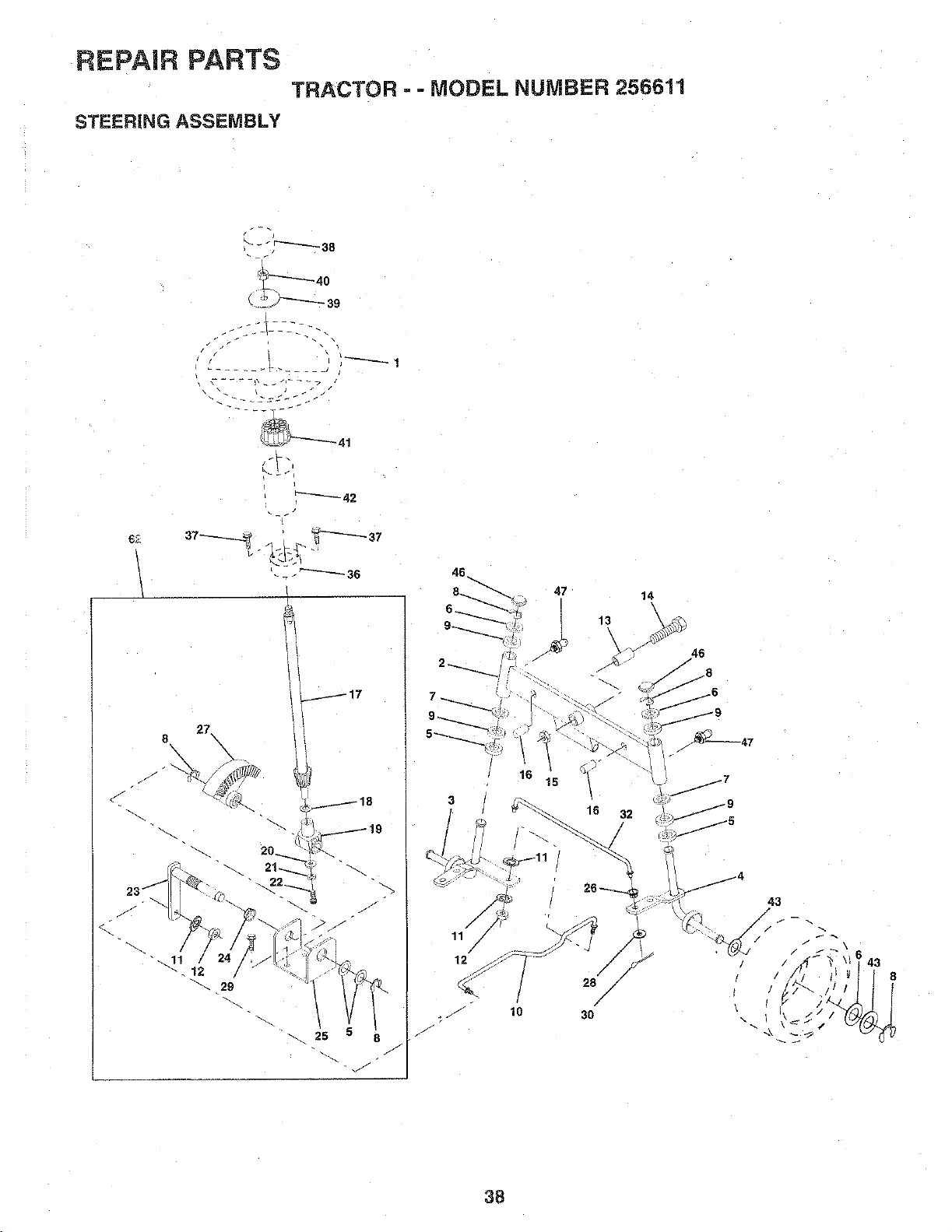
REPAIR PARTS
TRACTOR - - MODEL NUMBER 256611
STEERING ASSEMBLY
--:_JZZJj_-
6_
<
d
8
\
27.
25
J
2_
8
38

REPAIR PARTS
TRACTOR - - MODEL NUMBER 256611
STEER1NG ASSEMBLY
KEY PART
NO, NO,
1 121472X
2 142033
3 135227
135228
5 6266H
6 121748X
7 19272016
8 12000029
9 3366R
10 130468
11 STD551137
12 73610600
13 110438X
14 74011056
15 73901000
16 132624
17 128758
18 57079
19 124035X
2O 128684X
21 STD551125
22 71100410
23 127501
24 109818X
25 124036X
26 126847X
27 136874
28 19131416
29 17490612
30 STD561210
32 130465
35 145207
37 152927
38 126805X
39 1007!2K
40 STD541350
41 100711L
42 140216
43 121749X
46 12t232X
47 6855M
62 149682
DESCRIPTION
Steering Wheel
Axle Assembly, Front
Spindle Assembly, LH
Spindle Assembly, RH
Bearing, Race. Thrust. Hardened
Washer 25/32 x 1-5/8 x 16 Gauge
Washer 27/32 x 1-1/4 x 16 Gauge
Ring, Ktip
Bearing
Link. Drag
Washer, Lock
Nut. Hex Fin. 3/8-24 UNF
Spacer, Bearing, Front Axle
Bolt, Hex 5/8-11 UNCx3-1/2
Locknut. Hex. Jam, w/Washer Insert
5/8-11 UNC
Pin. Axle. Large 5/8 x 1.55/1.54
Shaft Assembly, Steering
Washer= Thrust .515 x .750 x .033
Support, Shaft
Washer. Shim 1/4 x 5/8 x .062
Washer
Screw Cap Socket Head Phos & Oil
Shaft Assembly, Pittman
Nyliner, Snap-In
Bracket. Steering
Bushing, Link Drag
Gear. Sector
Washer 13/32 x 7/8 x 16
Screw. Thdrol 3/8-16 x 3/4
Pin Cotter 1/8 x 3/4
Tie Rod
Bushin§ Steering
Screw
Insert. Cap, Steering Wheel
Washer .53 x 2.25 x .160
Nul
Adapter. Steering Wheel
Column. Steering
Washer 25/32 x 1-1/4 x 16 Gauge
Cap, Spindle
Fitting, Grease
Kit, Steering Assembly
NOTE: All component dimensions given in U.S. inches
1 inch = 25.4 mm
39
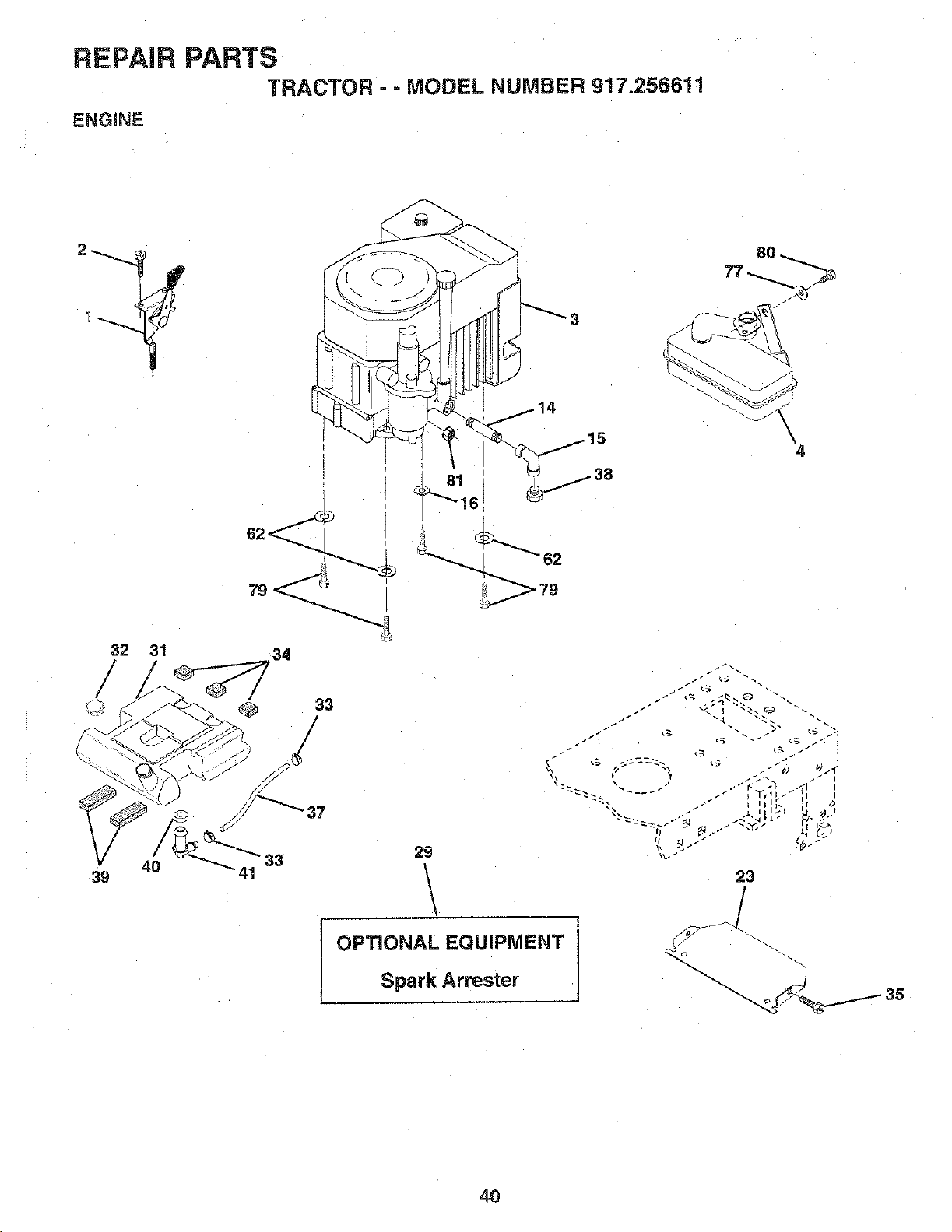
REPAIR PARTS
TRACTOR - =MODEL NUMBER 917,256611
ENGINE
14
32 31
39 4 _"41
34
33
/
/
37
33
'4
29
\
OPTIONAL EQUIPMENT
Spark Arrester
J
23
4O
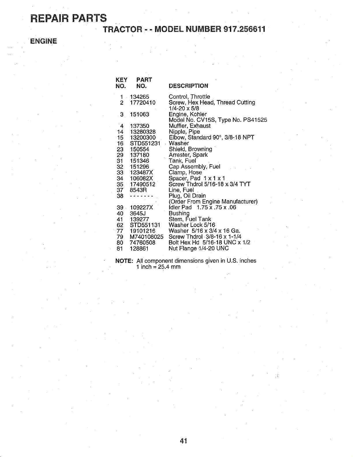
REPAIR PARTS
TRACTOR - - MODEL NUMBER 917.256611
ENGINE
KEY PART
NO. NO, DESCRIPTION
3
134265
17720410
151063
4 13735O
14 13280328
15 13200300
16 STD551231
23 150554
29 137180
31 151346
32 151296
33 123487X
34 106082X
35 17490512
37 8543R
38 .......
39 109227X
40 3645J
41 139277
62 STD551131
77 19101216
79 M740108025
80 74760508
81 128861
Control. Throttle
Screw. Hex Heac, Thread Cutting
1/4-20 x 5/8
Engine, Kohler
Model No. CV15S. Type No. PS41525
Muffler. Exhaust
Nipple, Pipe
Elbow, Standard 90°. 3/8-18 NPT
Washer
Shield, Browning
Arrester. Spark
Tank, Fuel
Cap Assembly, Fuel
Clamp. Hose
Spacer, Pad lx! xl
Screw Thdrel 5/16-18 × 3/4 TYT
Line, Fuel
Plug, Oil Drain
(Order From Engine Manufacturer)
dler Pad 1.75 x .75 x .06
Bushing
Stem. Fuel Tank
Washer Lock 5/16
Washer 5/16 x 3/4 x 16 Ga.
Screw Thdrol 3/8-16 x 1-1/4
Bolt Hex Hd 5/16-18 UNC x 1/2
Nut Flange 1/4-20 UNC
NOTE: All component dimensions given in U.S. inches
1 inch = 25.4 mm
41

REPAIR PARTS
TRACTOR - - MODEL NUMBER 917,256611
DECALS
KEY PART
NO. NO.
1 140123
2 140551
5 145006
6 STD541437
7 124181X
10 140552
11 120068X
12 121246X
13 121248X
14 72050411
15 134300
DESCRIPTION
Seat
Bracket, Pivot, Seat
Clip Push-In
Nut
Spring, Seat
Pan, Seat
Knob, Seat
Bracket, Switch Mounting
Bushing, Snap, Nylon
Bolt, Carriage 1/4-20 x 1-3/8
Spacer, Split
KEY PART
NO. NO. DESCRIPTION
16 121250X
17 123976X
18 124238X
2t 153236
22 STD54143t
24 19171912
25 127018X
27 17490608
28 150176
Spring
Nut, Flangelock 1/4 Grade 5
Cap, Spring, Seat
Bolt, Shoulder 5/16-18 UNC
Nut
Washer 17/32 x 1-3/16 x 12 Gauge
Bolt, ShouLder 5/16-18 x .62
Screw ThdreL 3/8-16 x 1/2
Bolt 5/16-18 UNC x 3/4 W/Sems
NOTE: All component dimensions given in U.S. inches
1 inch = 25.4 mm
42
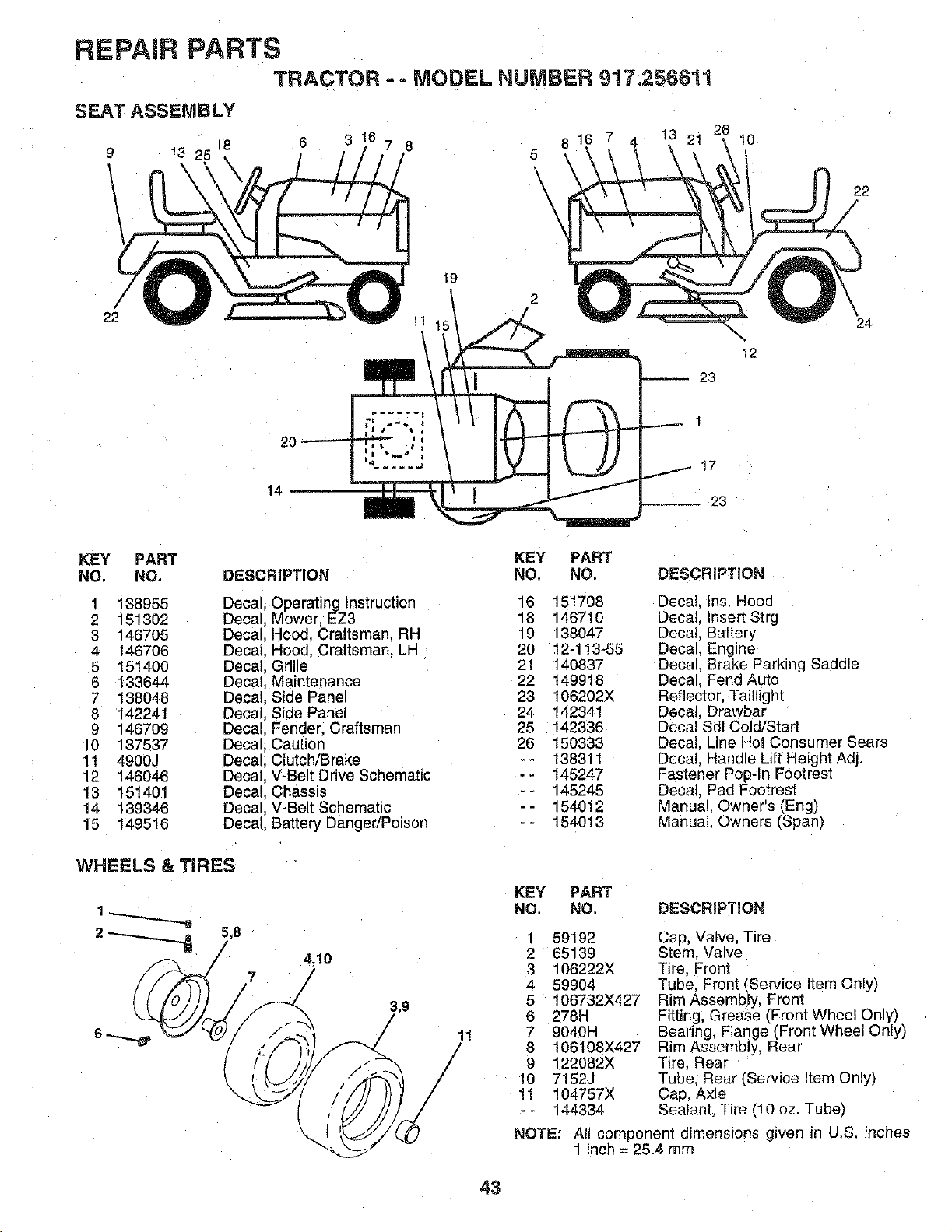
REPAIR PARTS
TRACTOR - - MODEL NUMBER 917;256611
22
20
14
6
3 7 8
11
19
5
\
16 7 4
-- 23
1
17
23
10
12
22
/
24
KEY PART
NO. NO.
1 138955
2 151302
3 146705
4 1467O6
5 151400
6 133644
7 138048
8 142241
9 146709
10 137537
11 4900J
12 146046
13 151401
14 139346
15 149518
DESCRIPTION
Decal, Operating Instruction
Decal, Mower, EZ3
Decal, Hood, Craftsman. RH
Decal, Hood, Craftsman. LH
Decal, Grille
Decal, Maintenance
Decal, Side Panel
Decal. Side Panel
Decal, Fender. Craftsman
Decal. Cautior
Decal, Clutch/Brake
Decal. V-Belt Drive Schematic
Decal. Chassis
Decal. V-Belt Schematic
Decal, Battery DangedPoison
KEY PART
NO. NO,
16 151708
18 146710
19 138047
20 12-113-55
21 140837
22 149918
23 106202X
24 142341
25 142336
26 150333
-- 138311
-- 145247
-- 145245
-- 154012
-- 154013
DESCRIPTION
Decal, qs. Hooc
Decal qsert Strg
Decal. Battery
Decal. Engine
Decal. Brake Parking Saddle
Decal. Fend Auto
Reflector. Taillight
Decal, Drawbar
Decal Sdl Cold/Starl
Decal. Line Hot Consumer Sears
Decal. Handle Lift Height Adj.
Fastener Pop-In Footrest
Decal. Pad Footrest
Manual. Owner's (Eng)
Manual. Owners (Span)
WHEELS & TIRES
4,10
11
/
KEY PART
NO. NO.
DESCRIPTION
1
2
3
4
5
6
7
8
9
10
11
59192
65139
106222X
59904
106732X427
278H
9040H
106108X427
122082X
7152J
104757X
144334
NOTE:
Cap, Valve. Tire
Stem. Valve
Tire, Front
Tube, Front (Service Item Only)
Rim Assembly, Fronl
Fitting, Grease (Front Wheel Only)
Bearing Flange (Front Wheel Only)
Rim Assembly. Rear
Tire, Rear
Tube. Rear (Service item Only)
Cap, Axle
Sealant, Tire fl0 oz. Tube)
All component dimensions given in U.S. inches
! inch = 25.4 mm
43
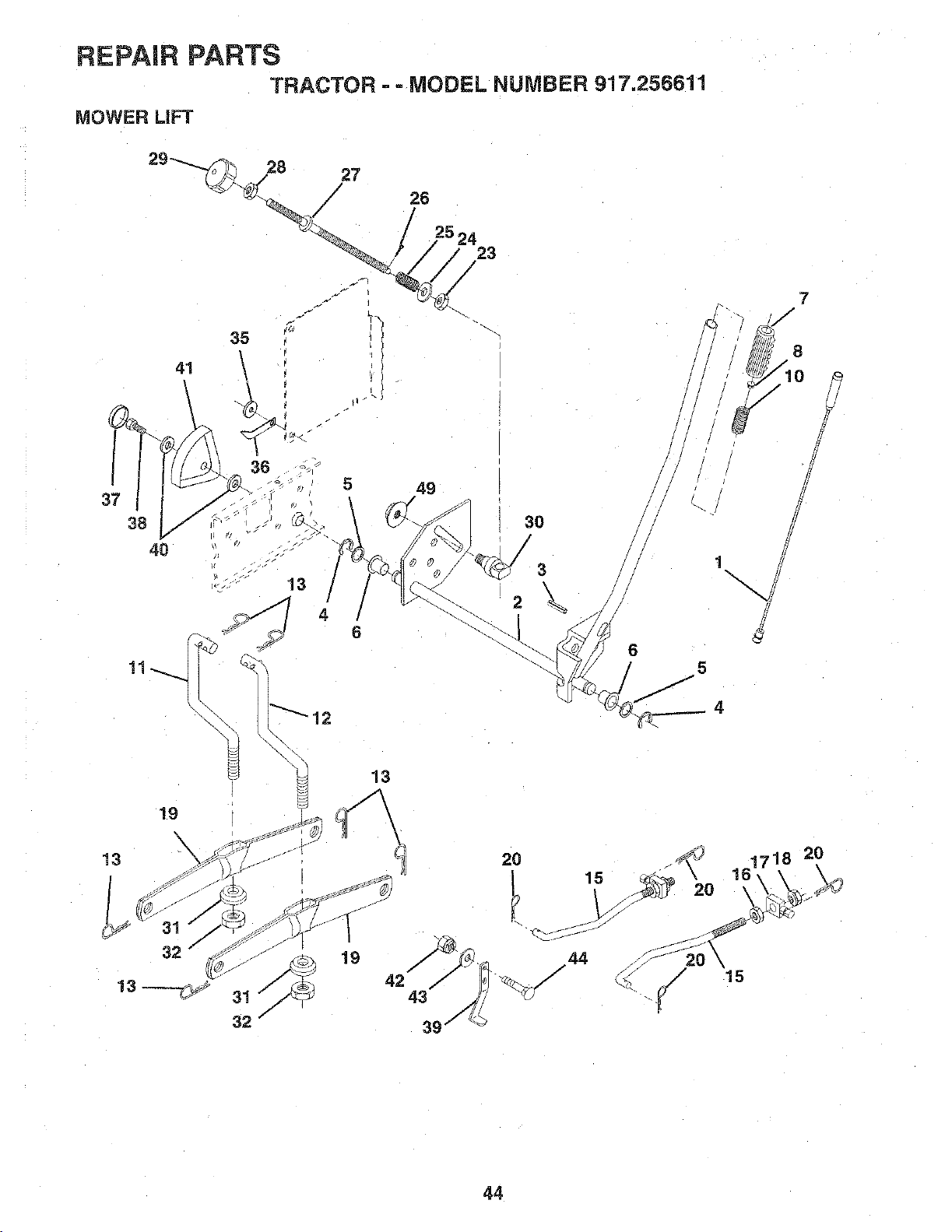
REPAIR PARTS
TRACTOR - - MODEL NUMBER 917.256611
MOWER LiFT
38
4O
" 13
5
2
30
/
3
13
19
42
43
2O
44
J
6
1
5
4
2O
J
15
7
1718 20
44
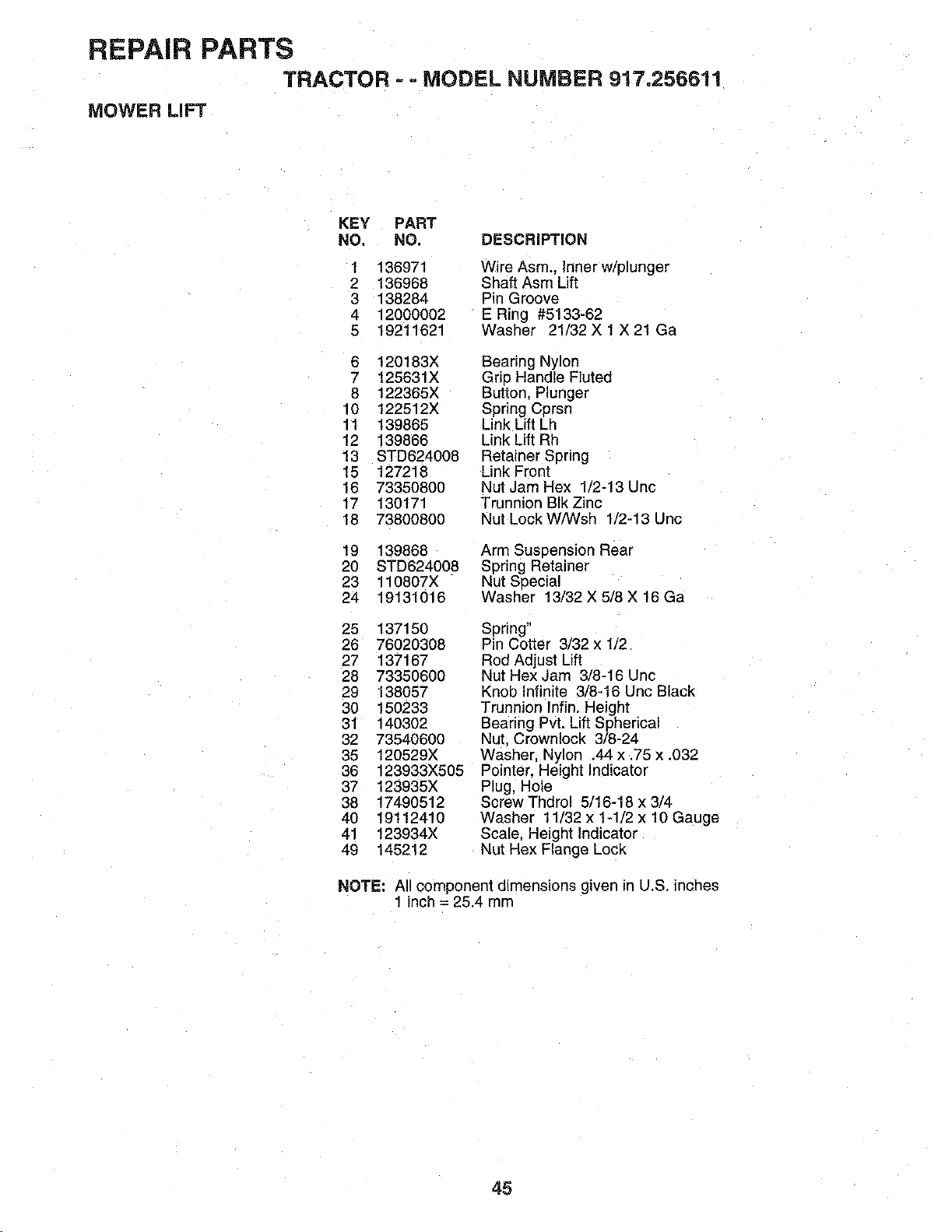
REPAIR PARTS
TRACTOR - - MODEL NUMBER 917.25661!
MOWER LIFT
KEY PART
NO, NO. DESCRIPTION
1
2
3
4
5
136971
136968
138284
12000002
19211621
Wire Asm., inner w/plunger
Shaft Asm Lift
Pin Groove
E Ring #5133-62
Washer 21/32 X 1 X 21 Ga
6 120183X
7 125631X
8 122365X
10 122512X
11 139865
12 139866
13 STD624008
15 127218
16 73350800
17 130171
18 73800800
Bearing Nylon
Grip Handle FLuted
Buttor Plunger
Spring Cprsn
Link Lift Lh
Link Lift Rh
Retainer Spring
Link Front
Nut Jam Hex 1/2-13 Uric
Trunnion BIk Zinc
Nut Lock W/Wsh 1/2-13 Unc
19 139868
20 STD624008
23 110807X
24 19131016
Arm Suspension Rear
Spring Retainer
Nut Special
Washer 13/32 X 5/8 X 16 Ga
25 137150
26 76020308
27 137167
28 73350600
29 138057
30 150233
31 140302
32 73540600
35 120529X
36 123933X505
37 123935X
38 17490512
40 19112410
41 123934X
49 145212
Spring"
Pin Cotter 3/32 x 1/2
Rod Adjust Lift
Nut Hex Jam 3/8-16 Unc
Knob Infinite 3/8-16 Unc Black
Trunnion Infin. Height
Bearing Pvt. Lift Spherical
Nut Crownlock 3/8-24
Washer, Nylon .44 x .75 x .032
Pointer. Height Indicator
Plug, Hole
Screw Thdrol 5/16-18 x 3/4
Washer 11/32 x 1-1/2 x 10 Gauge
Scale, Height indicator
Nut Hex Flange Lock
NOTE: All component dimensions given in U.S. inches
1 inch = 25.4 mm
45
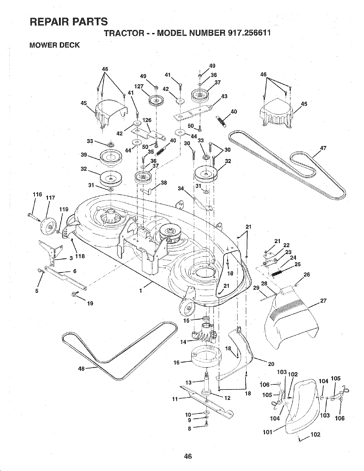
REPAIR PARTS
TRACTOR =- MODEL NUMBER 917.256611
MOWER DECK
5
46
49 41
\
127 42
21
46
21
22
45
12
105
46

REPAIR PARTS
TRACTOR - - MODEL NUMBER 917.256611
MOWER DECK
KEY PART KEY PART
NO. NO. DESCRIPTION NO. NO, DESCRIPTION
1 153125
3 138457
5 STD624008
6 130832
8 850857
9 STD551137
10 140296
11 152443
12 129895
13 137553
14 137152
15 110485X
16 140329
18 72140505
19 132827
20 145055
21 STD541431
22 134753
23 131267
24 105304X
25 123713X
26 110452X
27 145325
28 19111016
29 131491
30 138776
31 129963
32 153531
33 137266
34 144945
35 17490628
36 STD651037
37 131494
Mower Housing (Weldment) 38 137554
Bracket Asm., Sway Bar 39 144917
Retainer Spring 40 137273
Arm, Suspension. Rear (Sway Bar) 41 17490620
Bolt. Patched 3/8-24 x 1-1/4 Gr. 8 42 122052X
Washer, Lock Hvy., Unptated 3/8 43 144949
Washer. Hard Blade. Mower 44 133943
Vented 45 145059
Blade, 46" Mower Deck 46 137729
Bearing, Ball, Mandrel #6204 47 144959
Shaft Asm. w/Lower Bearing 48 148763
HInCludesKey No. 12) 49 STD541437
ousing, Mandrel 50 72110612
Bearing, Ball, Mandrel 101 145579
Stripper. Mower Round 102 71161010
Bolt. Carriage 5/16-18 x 5/8 103 STD551110
Bolt. Hex Head, Shoulder 5/16-18 104 19061216
Baffle. Vortex Mower 46" 105 130758
Nut, Crownlock 5/16-18 UNC 106 2029J
Stiffiner. Bracket 116 137644
Bracket. Deflector 117 133957
Cap, Sleeve 118 73930600
Spring Torsion, Deflector 119 19121414
Nut. Push 126 144948
Shield. Deflector Mower 127 146763
Washer 11/32x5/8x16Ga. -- 151775
Rod. Hinge
Screw, Hex Heaa.. Thdroll
Washer. Spacer Mower Vented
Pulley, Mandrel -- 143651
Nut, Fig. Top Lock Cntr. 9/16
Anchor, Spring Deck 46"
Screw, Thdroll 3/8-16 x 1-3/4 Tytt
Washer 13/32 x 13/16 x 16 Ga.
Pulley, Idler, Flat
Keeper, Belt, idler
Pulley, Idler. Driven
Spring, Secondary 44/46/50 Vent
Screw. Thdroll 3/8-16 x 1-1/4 Tytt
Spacer. Retainer
Arm, Idler Secondary
Washer. Hardened
Cover, Mandrel Deck
Screw. Thdroll. 1!4-20 x 5/8
V-Belt. Mower. Secondary
V-Belt. Mower, Primary
Nut. Crownlock 3/8-16 UNC
Bolt. Carriage 3/8-16 x 1-1/2 Gr. 5
Cover Mulching
Screw
Washer. Lock #10
Washer
Latch Asm. Bagger
Nut. Weld
Bolt. Shoulder
Gauge Wheel, Wide
Nut. Centerlock 3/8-16 UNC
Washer 3/8 x 7/8 x 14 Ga.
Arm. Idler. Primary Deck 46"
Pulley, Idler. V-Groove Dim. 4.25
Deck Complete (Std. Deck-Order
separately mulcher plate and gauge
wheel components Key Nos. 101-
106 and 118-118}
Mandrel Asm 44"/50" Service
(Includes Key Nos. 8-10. 12-15, 31
and 33}
NOTE: All component dimensions given tn U.S. inches
1 inch= 25.4 mm
47
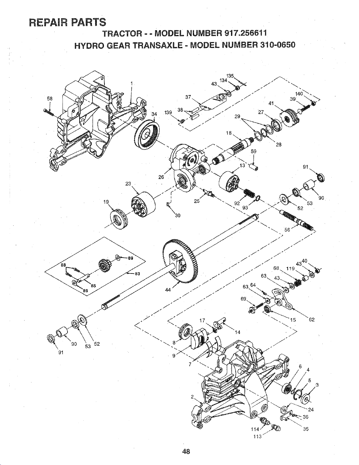
REPAIR PARTS
TRACTOR - - MODEL NUMBER 917o256611
HYDRO GEAR TRANSAXLE =MODEL NUMBER 310=0650
58
/
44 "
25
28
59
17
35
113_
48
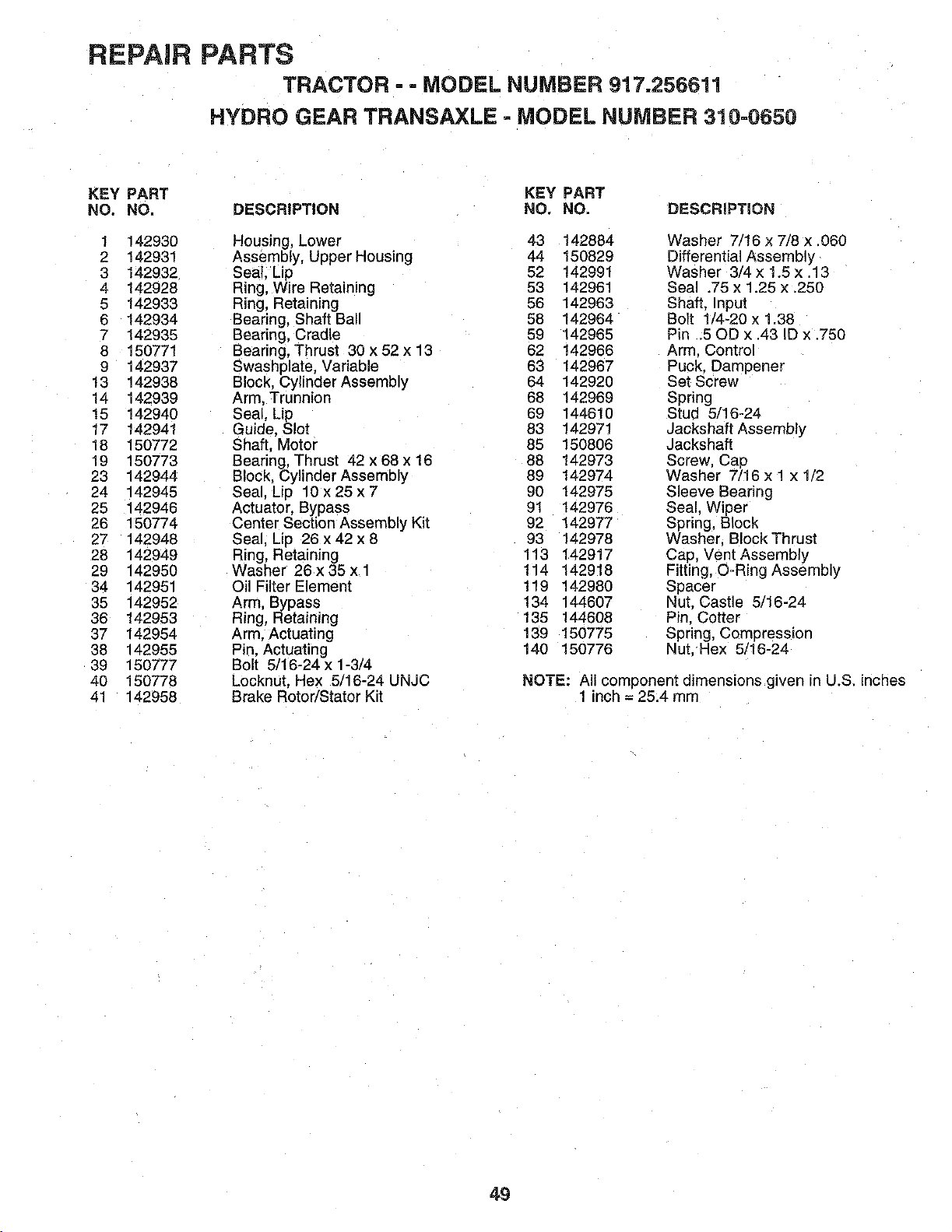
REPAIR PARTS
TRACTOR =- MODEL NUMBER 917.256611
HYDRO GEAR TRANSAXLE - MODEL NUMBER 310-0650
KEY PART KEY PART
NO. NO. DESCRIPTION NO. NO. DESCRIPTION
1 142930 Housing, Lower 43 142884 Washer 7/16 x 7/8 x.060
2 142931 Assembly, Upper Housing 44 150829 Differential Assembly
3 142932 Seal. Lip 52 142991 Washer 3/4 x !.5 x .13
4 142928 Ring, Wire Retaining 53 142961 Seal .75 x 1.25 x.250
5 142933 Ring, Retaining 56 142963 Shaft. input
6 142934 Bearing, Shaft Ball 58 142964 Bolt 1/4-20 x 1.38
7 142935 Bearing, Cradle 59 142965 Pin .50D x .43 ID x .750
8 150771 Bearing, Thrust 30 x 52 x 13 82 142966 Arm. Control
9 142937 Swashplate, Variable 63 142967 Puck. Dampener
13 142938 Block. Cylinder Assembly 64 142920 Set Screw
14 142939 Arm, Trunnion 68 142969 Spring
15 142940 Seal, Lip 69 144610 Stud 5/16-24
17 142941 Guide, Slot 83 142971 Jackshaft Assembly
18 150772 Shaft, Motor 85 150806 Jackshaft
19 150773 Bearing, Thrust 42 x 68 x 16 88 142973 Screw, Cap
23 142944 Block. Cylinder Assembly 89 142974 Washer 7/16 x 1 x 1/2
24 142945 Seal, Lip 10 x 25 x 7 90 142975 Sleeve Bearing
25 142946 Actuator, Bypass 91 142976 Seal, Wiper
26 150774 Center Section Assembly Kit 92 142977 Spring, Block
27 142948 Seal, Lip 26 x 42 x 8 93 142978 Washer Block Thrust
28 142949 Ring, Retaining 113 142917 Cap, Vent Assembly
29 142950 Washer 26x 35 x 1 114 142918 Fitting, O=Ring Assembly
34 142951 Oil Filter Element 119 142980 Spacer
35 142952 Arm, Bypass 134 144607 Nut. Castle 5/16-24
36 142953 Ring, Retaining 135 144608 Pin. Cotter
37 142954 Arm. Actuating 139 150775 Spring, Compression
38 142955 Pin. Actuating 140 150776 Nut. Hex 5/16-24
39 150777 Bolt 5/16-24 x 1-3/4
40 150778 Locknut, Hex 5/16-24 UNJC NOTE: All component dimensions given in U.S. inches
41 142958 Brake Rotor/Stator Kit 1 inch = 25.4 mm
49
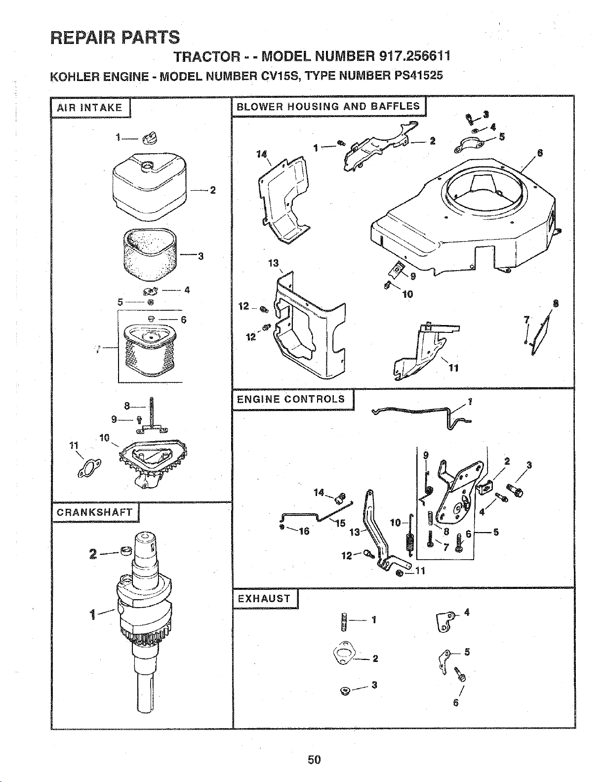
REPAIR PARTS
TRACTOR - - MODEL NUMBER 917.256611
KOHLER ENGINE - MODEL NUMBER CV15S, TYPE NUMBER PS41525
--2
3
--@
10
13
12-_,
12
1o
g
2 3
/ /
/
_ - --3
8
5O
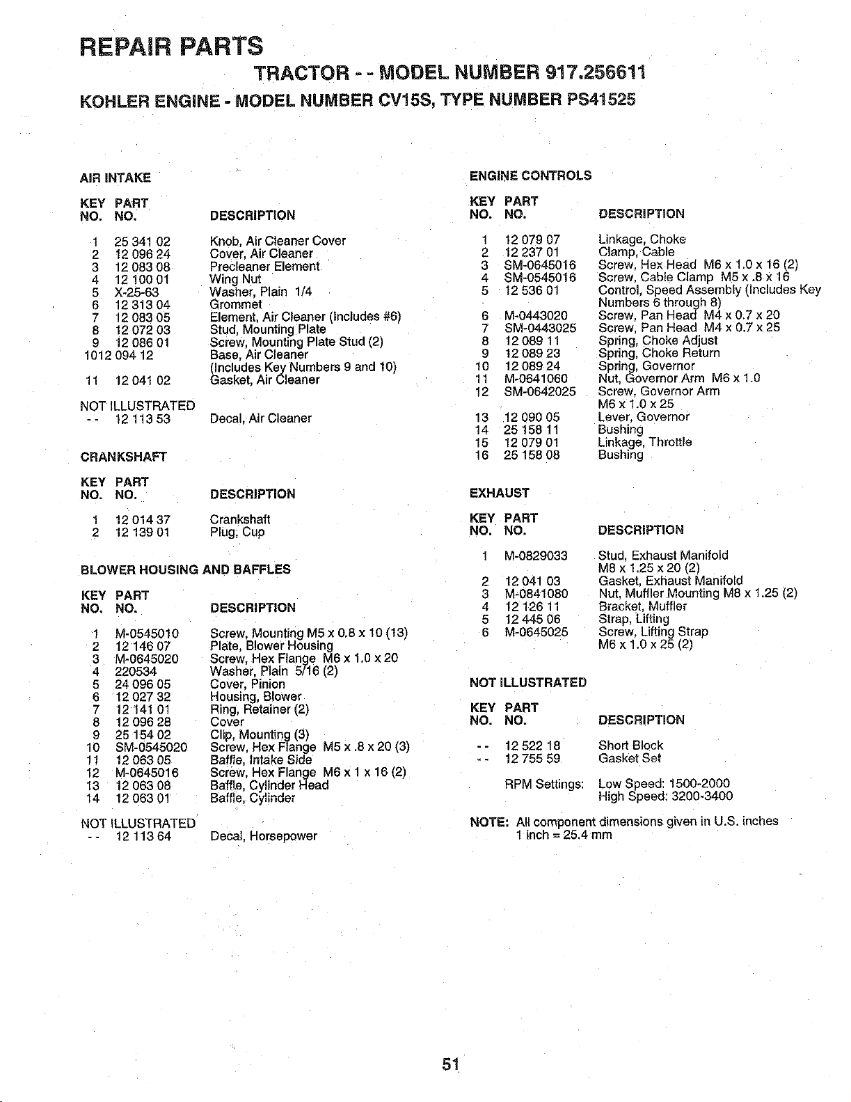
REPAIR PARTS
TRACTOR - =MODEL NUMBER 917,256611
KOHLER ENGINE = MODEL NUMBER CV15S, TYPE NUMBER PS41525
AIR INTAKE
ENGINE CONTROLS
KEY PART KEY PART
NO, NO. DESCRIPTION NO. NO. DESCRIPTION
1 25 341 02 Knob. Air Cleaner Cover i 12 079 07
2 t 2 096 24 Cover. Air Cleaner 2 12 237 01
3 12 083 08 Precleaner Element 3 SM-0645016
4 12 100 01 Wing Nut 4 SM-0545016
5 X-25-63 Washer. Plain 1/4 5 12 536 01
6 12 313 04 Grommel
7 12 083 05 Element. Air Cleaner (includes #6) 6 M-0443020
8 12 072 03 Stud, Mounting Plate 7 SM-0443025
9 12 086 01 Screw. Mounting Plate Stud (2) 8 12 089 11
1012 094 12 Base. Air Cleaner 9 12 089 23
(Includes Key Numbers 9 and 10) 10 12 089 24
11 12 041 02 Gasket. Air Cleaner 11 M-0641060
f2 SM-0642025
NOT ILLUSTRATED
- - 12 113 53 Decal, Air Cleaner 13 12 090 05
14 25 158 11
15 12 079 01
CRANKSHAFT 16 25 158 08
KEY PART
NO. NO. DESCRIPTmON EXHAUST
1 12 01437 Crankshaft KEY PART
2 12 139 01 Plug, Cup NO. NO,
BLOWER HOUSING AND RAFFLES
i M-0829033
2 12 041 03
KEY PART 3 M-0841080
NO. NO. DESCRIPTION 4 12 126 11
5 12 445 05
1 M-0545010 Screw, Mounting M5x 0,8x 10 (13) 6 M-0645025
2 12 146 07 Plate, Slower Housing
3 M-0645020 Screw, Hex Flange M6 x 1.0 x 20
4 220534 Washer. Plain 5/16 (2)
5 24 096 05 Cover, =inion
6 t2027 32 Housing, Blower
7 12 141 01 Ring, Retainer (2_
8 1209628 Cover
9 26 154 02 Clip, Mounting (3)
10 SM-0545020 Screw. Hex Flange M5 x .8 x 20 (3)
11 12 063 05 Baffle, Intake Side
12 M-0645016 Screw. Hex Flange _16x 1 x 16 [2)
13 12 063 08 Baffle, Cylinder Head
14 12 063 01 Baffle, Cylinder
NOT ILLUSTRATED
-- 12 113 64
Linkage, Choke
Clamp, Cable
Screw. Hex Head £16x 1.0 x 15 (2)
Screw. Cable Clamp M5 x .8 x 16
ControL. Speed Assembly (includes Key
Numbers 6 through 8)
Screw. Pan Head V14x 0.7 x 20
Screw. Pan Head M4 x 0.7 x 25
Spring, Choke Adjust
Spring, Choke Return
Spring, Governor
Nut. Governor Arm M6 x 1.0
Screw Governor Arm
M6 x 1.0 x 25
Lever. Governor
Bushing
Linkage, Throttle
Bushing
Decal. Horsepower
DESCRIPTION
Stud Exhaust Manifold
M8 x 1.25 x 20 (2)
Gasket. Exhaust Manifold
Nut. Muffler Mounting M8 x 1.25 (2)
Bracket. Muffler
Strap, Lifting
Screw, Lifting Strap
M6 x 1.0 x 25 (2_
NOT ILLUSTRATED
KEY PART
NO. NO, DESCRIPTION
-- 12 522 18 Short Block
- 12 755 59 Gasket Set
RPM Settings: Low Speed: 1500-2000
High Speed: 3200-3400
NOTE: All component dimensions given in U.S. inches
1 inch = 25.4 mm
51
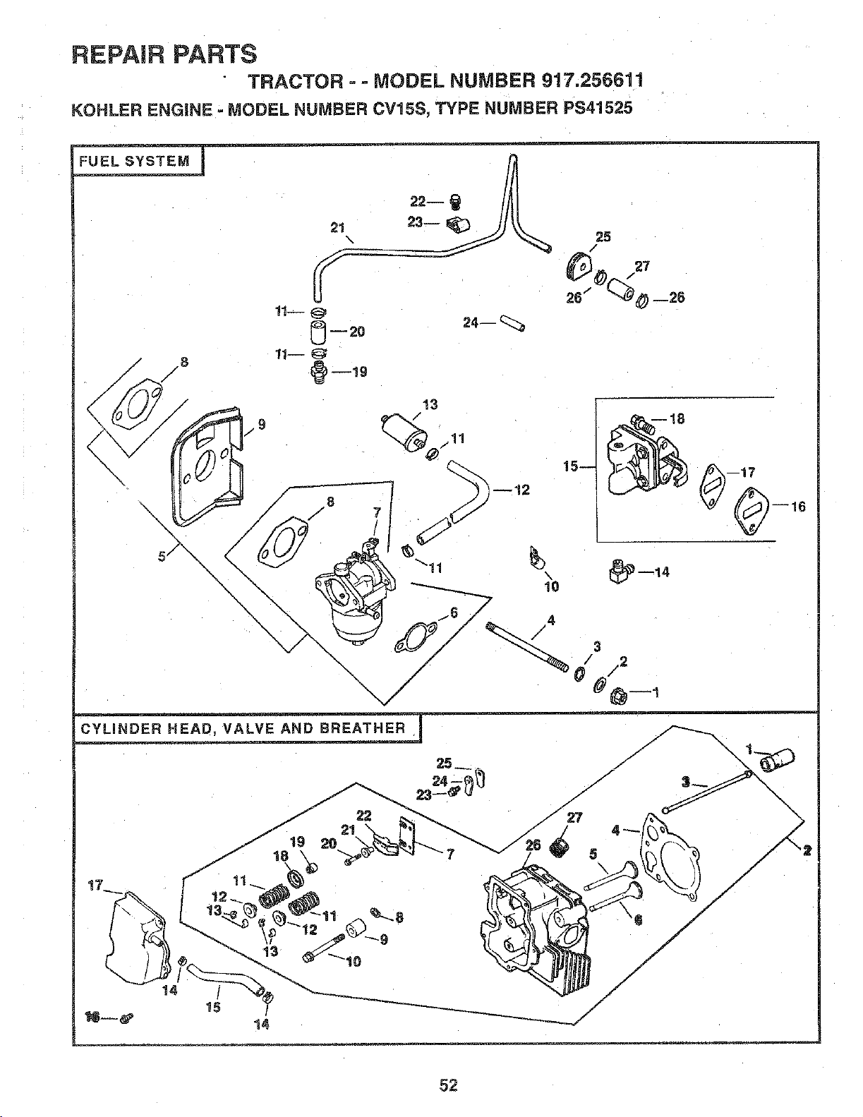
REPAIR PARTS
TRACTOR =- MODEL NUMBER 917.256611
KOHLER ENGINE - MODEL NUMBER CV15S, TYPE NUMBER PS41525
FUEL SYSTEM
21
\
11 @
0 2o
_)--19
24-- _::_
25
/
20 -',__28
\\ .,/// _ 3
##@ 1
CYLINDER HEAD, VALVE AND BREATHER
25
/
/
23 /
/19/19 20 22 __ 27
21 4 "-'-.
J 18 _, 7 5
f
/
/
/
/
/
/
/
/
52
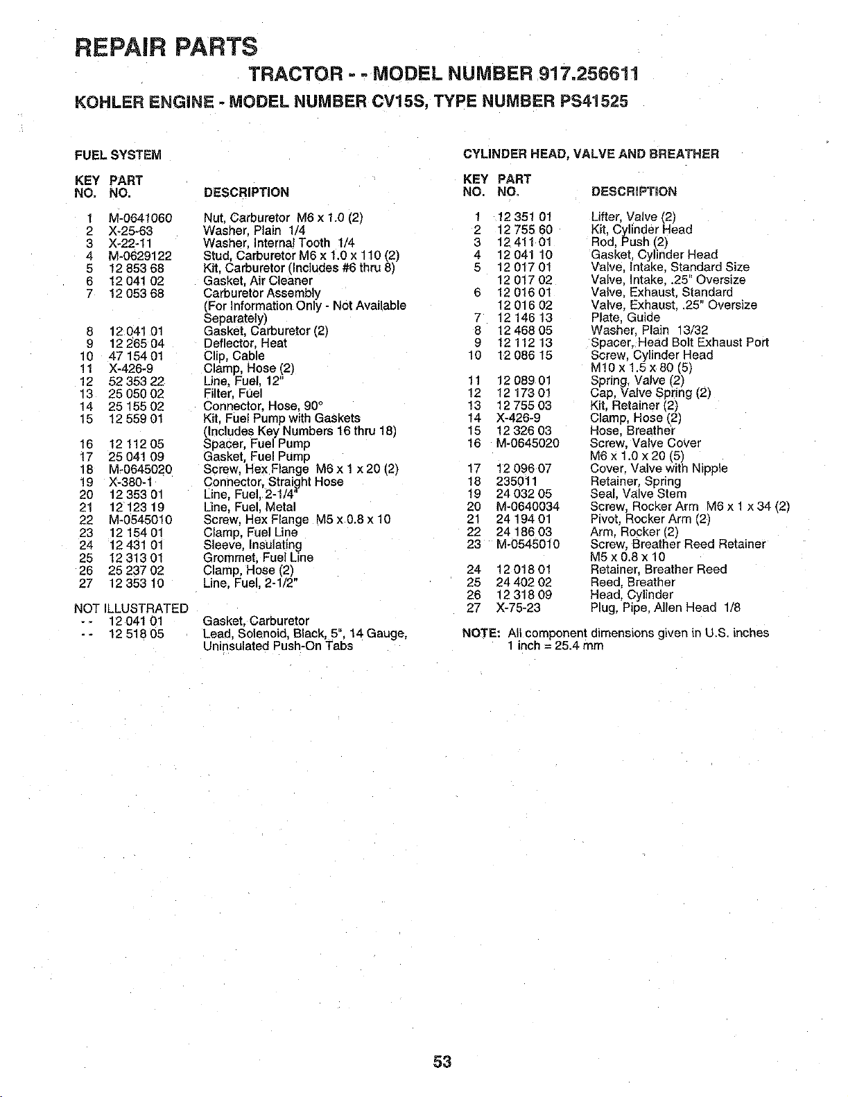
REPAIR PARTS
TRACTOR - MODEL NUMBER 917.256611
KOHLER ENGINE - MODEL NUMBER CV15S, TYPE NUMBER PS41525
FUEL SYSTE_
KEY PART
NO. NO. DESCRIPTION
1 M-0641060
2 X-25-63
3 X-22-11
4 M-0629122
5 12 853 68
6 12041 02
7 12 053 68
8 12 041 01
9 1226504
10 47 154 01
11 X-426-9
12 52 353 22
13 25 050 02
14 25 155 02
15 12 559 01
16 1211205
17 25041 09
18 M-0645020
19 X-380-1
20 12 353 01
21 12 123 19
22 M-0545010
23 12 154 01
24 12 431 01
25 1231301
26 25 237 02
27 12 353 10
NOT ILLUSTRATED
- - 12 041 01
-- 1251805
CYLINDER HEAD, VALVE AND BREATHER
KEY PART
NO, NO, DESCRIPTION
Nut. Carburetor M6 x 1.0 (21 1 12351 01
Washer Plai_ 1/4 2 1275560
Washer InternelTooth t/4 3 12411 01
Stud, Carburetor M6 x 1.0 x 110 (2) 4 12 041 10
Kit. Carburetor (Includes #6 thru 8) 5 12 017 01
Gasket. Air Cleaner 12 017 02
Carburetor Assembly 6 12 016 0t
_For Information Only - Not Available 12 016 02
eparately) 7 12 146 13
Gasket. Carburetor (2) 8 12 468 05
Deflector, Heat 9 12 112 13
Clip, Cable 10 12 086 15
Clamp, Hose (2)
Line, Fuel. 12 11 12 089 01
Filter, Fuel 12 12 173 01
Connector. Hose. 90° 13 12 755 03
Kit, Fuel Pumpwith Gaskets 14 X-426-9
slnCludes Key Numbers 16 thru 18) 15 12 326 03
pacer. Fuel Pump 16 M-0845020
Gasket, Fuel Pump
Screw. HexFlange M6xlx20(2) 17 1209607
Connector, Straight Hose 18 235011
Line. Fuel, 2-1/4" 19 24 032 05
Une. Fuel Metal 20 M-0640034
Screw HexFlange M5x0.8xl0 21 2419401
Clamp, Fuel Line 22 24 186 03
Sleeve. Insulating 23 M-0545010
Grommet. Fuel Line
Clamp, Hose (2)
Line. Fuel. 2-1/2"
Gasket. Carburetor
Lead, Solenoid, Black, 5". 14 Gauge,
Uninsulated Push-On Tabs
24 1201801
25 24 402 02
26 1231809
27 X-75-23
Lifter. Valve (21
Kit, Cylinder Head
Red. Push (2_
Gasket, Cylinder Head
Valve. Intake. Standard Size
Valve. Intake..25" Oversize
Valve. Exhaust. Standard
Valve. Exhaust..25" Oversize
Plate. Guide
Washer. Plain 13/32
Spacer. Head Belt Exhaust Port
Screw. Cylinder Head
M!0 x 1.5x 80 [5)
Spring, Valve [2)
Cap, Valve Spring (2)
Kit, Retainer (2)
Clamp, Hose (2)
Hose. Breather
Screw. Valve Cover
M6 x 1.0 x 20 (5)
Cover. Valve with Nipple
Retainer. Spring
Seal. Valve Stem
Screw. Rocker Arm M6 x 1 x 34 (2)
Pivot. =locker Arm (2)
Arm. Rocker (2)
Screw Breather Reed Retainer
M5x0.8x 10
Retainer. Breather Reed
Reed, Breather
Head. Cylinder
Plug, Pipe. Allen Head 1/8
NOTE: All component dimensions gLven in U.S. inches
1 inch = 25.4 mm
53
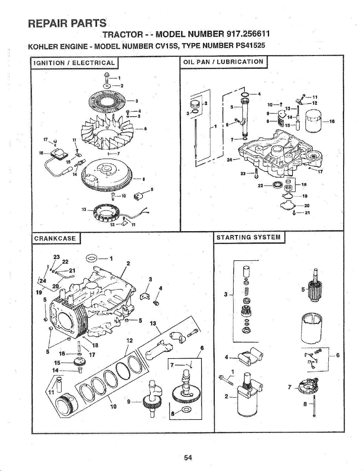
REPAIR PARTS
TRACTOR - - MODEL NUMBER 917.256611
KOHLER ENGINE - MODEL NUMBER CV15S, TYPE NUMBER PS41525
_ELECTRI CAL ....
,o-_ & o-,
c.A._ASE .....
o_L_./_.uB.IcA_:Jo. - °
1
54
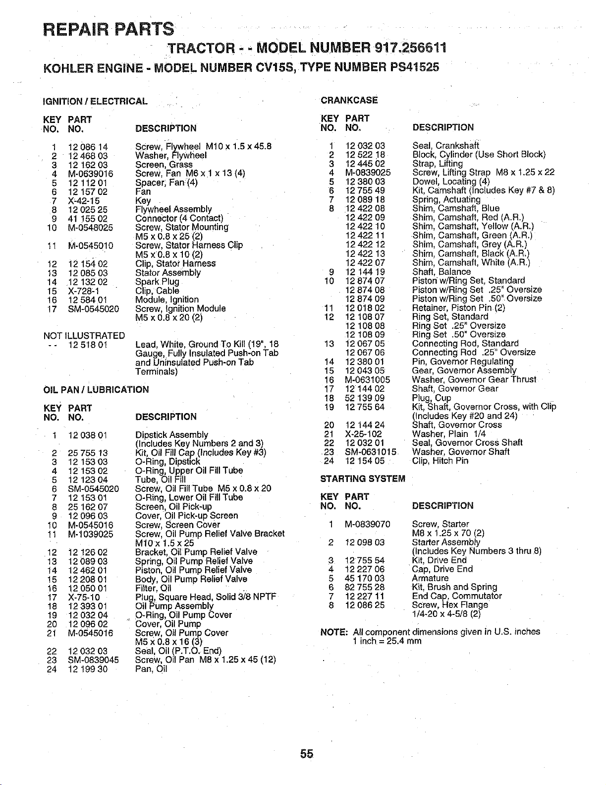
REPAIR PARTS
TRACTOR - - MODEL NUMBER 917.25GGll
KOHLER ENGINE - MODEL NUMBER CV15S, TYPE NUMBER PS41525
IGNITION / ELECTRICAL
CRANKCASE
KEY PART KEY PART
NO. NO, DESCRIPTION NO. NO, DESCRIFTION
DESCRIPTION
1 12 086 14 Screw, Flywheel M10 x 1.5 x 45.8 1 12 032 03
2 12 468 03 Washer, _:lywl;[eel 2 12 522 18
3 12 162 03 Screen, Grass 3 12 445 02
4 M-0639015 Screw, Fa_ M6 x 1 x 13 (4) 4 M-0839025
5 121120! Spacer. Fan (4) 5 12 380 03
6 1215702 Fan 6 t275549
7 ×-42-15 Key 7 12 089 18
8 12 025 25 Flywheel Assembly 8 12 422 08
9 41 !55 02 Connector (4 Contact) 12 422 09
10 M-0548025 Screw, Stator Mounting 12 422 10
M5 x 0.8 x 25 (2) 12 422 11
11 M-0545010 Screw. Stator Harness Clip 12 422 12
M5 x 0.8 x 10 (2) 1242213
12 12 15,_ 02 Clip, Stator Harness 12 422 07
_3 12 085 03 Stator Assembly 9 12 144 19
14 12 132 02 Spark Plug 10 12 874 07
15 X-728-1 Clip, Cable 12 874 08
16 12 584 01 Module, Ignition 12 874 09
17 SM-0545020 Screw, Ignition Module 11 12 018 02
M5 x 0.8 x20 (2) 12 1210807
12 108 08
NOT ILLUSTRATED 12 108 09
- - 12 518 01 Lead. White. Ground To Kill (19", 18 13 12 067 05
Gauge, Fully Insulated Push-on Tab 12 067 06
and Uninsulated Push-on Tab 14 12 380 01
Terminals) 15 12 043 05
16 M-0631005
OIL PAN / LUBRICATION 17 12 144 02
18 5213909
KEY PART 19 12 755 64
NO. NO.
1 1203801
2 25 755 13
3 1215303
4 1215302
5 1212304
6 SM-0545020
7 1215301
8 25 162 07
9 12 096 03
10 M-0545016
11 M-1039025
12 1212602
13 12 089 03
14 1246201
15 1220801
16 12 050 01
17 X-76-10
18 1239301
19 12 032 04
20 12 096 02
21 M-0545016
Dipstick Assembly
(Includes Key Numbers 2 and 3)
Kit, Oil Fill Cap (Includes Key #3)
O-Ring, Dipstick
O-Ring, Upper Oil Fill Tube
Tube, Oil F_II
Screw. Oil Fill Tube M5 x 0.8 x 20
O-Rin£, Lower Oil Fill Tube
Screen, Oil Pick-up
Cover, Oil Pick-ue Screen
Screw, Screen Cover
Screw. Oil Pump Relief Valve Bracket
MlOx 1.5 x 25
Bracket. Oil Pump Relief Valve
Spring, Oil Pump Relief Valve
Piston. Oil Pump Relief Valve
Body, Oil Pump Relief Valve
Filter, Oil
Plug, Square Head, Solid 3/8 NPTF
Oil Pump Assembly
O-Ring, Oil Pump Cover
Cover, Oil Pump
Screw. Oil Pump Cover
M5 x 0.8 x 16 (3)
Seal. Oil (P.T.O. End)
Screw, Oil Pan M8 x 1.25 x 45 (12)
Pan. Oil
22 12 032 03
23 SM-0839045
24 12 199 30
20 12 144 24
21 X-25-102
22 12 032 01
23 SM-0631015
24 12 154 05
STARTING SYSTEM
Seal. Crankshaft
Block. Cylinder (Use Short Blockj
Strap, Lifting
Screw. Liftinc Strap M8 x 1.25 x 22
9owel, Locating (4)
Kit. Camshaft {'Includes Key #7 & 8)
Spring, Actuatinc
Shim Camshaft. Blue
Shim Camshaft, Red (A.R.)
Shim. Camshaft. Yellow (A.RJ
Shim. Camshaft, Green (A.R.)
Shim Camshaft, Grey (A.R.)
Shim Camshaft, Black (A.R.)
Shim Camshaft. White (A.R.)
Shaft. Balance
Piston'w/Ring Set, Standard
Piston w/Ring Sel .25" Oversize
Piston w/Ring Set .50" Oversize
Retainer. Piston Pin (2)
Ring Set. Standard
Ring Set .25" Oversize
Ring Set .50" Oversize
Connecting Rod. Standard
Connecting Rod .25 Oversize
Pin, Governor Regulating
Gear. Governor Assembly
Washer. Governor Gear Thrust
Shaft Governor Gear
Plug, Cup
Kit. Shaft. Governor Cross. with Clip
_ncludes Key #20 and 24j
haft. Governor Cross
Washer. Plain 1/4
Seal. Governor Cross Shaft
Washer, Governor Shaft
Clip, Hitch Pin
KEY PART
NO, NO.
DESCRIPTION
3
4
5
6
7
8
M-0839070
I2 098 03
12 755 54
12 227 06
45 170 03
82 755 28
1222711
12 086 25
Screw. Starter
M8 x 1.25 x 70 (2)
Starter Assembly
(Includes Key Numbers 3 thru 8)
Kit. Drive End
Cap, Drive End
Armature
Kit. Brush and Spring
End Cap, Commutator
Screw. Hex Flange
1/4-20 x 4-5/8 12t
NOTE: All component dimensions given in U.S. inches
1inch = 25.4 mm
55

SERVICE NOTES
56

SERVICE NOTES
57

_ .... ==,
SERVICE NOTES
58

SUGGESTED GUIDE FOR SiGHTiNG SLOPES FOR SAFE OPERATION
I ""
SIGHTING
GUIDE
ONLY RIDE UP AND DOWN HILL,
NOT ACROSS HiLL
SIGHT AND HOLD THiS LEVEL WiTH
SKY LINE OR TREE.
15 ° MAX.
t _ Operate your Tractor up and down the face of slopes (not
greater than 15°), never across the face. Make turns gradu-
O ally to prevent tipping or loss of control. Exercise extreme
caution when changing direction on slopes.
SEARS
OWNER'S
MANUAL
MODEL NO.
917.256611
IF YOU NEED
REPAIR SERVICE
OR PARTS:
FOR REPAIR SERVICE, CALL
THIS TOLL FREE NUMBER:
1-800-4-REPAIR
(1-800-473-7247)
FOR REPLACEMENT PARTS
INFORMATION AND
ORDERING, CALL THIS
TOLL FREE NUMBER:
1-800-FON-PART
(1-800-366-7278)
FOR CONSUMER ASSISTANCE
HOT LINE, CALL THIS
TOLL FREE NUMBER:
i-800=659-5917
®
15.5 HP
ELECTRIC START
46" MOWER
AUTOMATIC (HYDROSTATIC)
DRIVE
LAWN TRACTOR
Each tractor has its own model number. Each engine has
its own model number.
The model number for your tractor will be found on the
model plate located under the seat.
The model number for your engine will be found on the
blower housing of the engine.
All parts listed herein may be ordered from any Sears,
Roebuck and Co. Service Center/Department and most Re-
tail Stores.
WHEN ORDERING REPAIR PARTS, ALWAYS GIVE THE
FOLLOWING INFORMATION:
" PRODUCT- TRACTOR
• MODEL NUMBER - 917.256611
• ENGINE MODEL NO. - CV15S-P41525
• PART NUMBER
• PART DESCRIPTION
Your Sears merchandise has added value when you
consider Sears has service units nationwide staffed with
Sears trained technicians.., professional technicians
specifically trained to insure that we meet our pledge to
you, we service what we sell.
154012 02.13.96 JH Printed in U.S.A.


