Loading ...
Loading ...

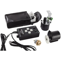
USING THE DRIVE
The hand control consists of two switches and four control buttons.
• The switch marked "N/Off/S" turns the power to the motor on and off as well as changing the
direction of the motors. Turn the switch to “N” to begin tracking for the northern hemisphere.
Changing the switch to "S" will reverse the polarity of the motor to track stars in the southern
hemisphere.
• The switch marked “2X/4X/8X” determines the rate at which the motor will move when the hand
controller buttons are pressed. 2X, twice the sidereal rate, is used for guiding on a star when
doing long exposure astrophotography. 4X, four times sidereal, is used for centering objects in
the eyepiece; and 8X, eight times sidereal, can be used for centering objects in the finderscope
as well as the eyepiece.
• The four push buttons control the motor drive direction. The “Up” and “Down” buttons control the
telescope in declination (DEC). The “Left “ and “Right” buttons control the telescope in Right
Ascension (RA). The direction for each button will be reversed when switched to the southern
hemisphere position.
The Declination motor can be disengaged in order to manually move the mount via the slow motion
control knob. To override the motor, the lock on the clutch gear assembly must be loosened. This
will allow the gear hub to rotate independently from the actual gear. For Declination, loosen the
clutch wheel on the gear assembly and turn the slow motion control knob attached to the shaft of the
clutch gear assembly. Tighten the clutch wheel to re-engage the tracking.
Troubleshooting?
A common problem with the DA-CG-4 motor drive on the CG-4 mount is the worm gears are
sometimes fitted too tightly to the helical gears. This causes the motors to bind up. Conversely, the
worm gear may fit too loosely, causing excess backlash in the motors. In either case the worm may
need to be adjusted. The procedure and the assemblies are the same for the DEC and the R.A. The
only difference is the location. The DEC worm assembly is located on the top of the mount. It is the
box to which the DEC slow motion knob is attached. To recognize if the gears are meshing too
tightly, turn the R.A. manual slow motion control. If it is noticeably hard to turn then it should be
loosened. If you cannot tell, then the motor will let you know. It will either run or it won’t.
To Adjust the Worm Gears:
1. Remove the motor drive assembly.
2. Locate the worm assembly on either the R.A. or Dec axis. This is the box to which the slow
motion knobs are attached.
3. Locate the 4 Allen head cap screws that hold the worm gear assembly in place. Two are located
underneath the box with a set screw located in between. Two are located on the backside of the
mount.
4. Slightly loosen all four screws.
5. Turn the center set screw on the underside about a quarter turn clockwise (to loosen the R.A.
worm assembly) or a quarter turn counter-clockwise (to tighten the worm gear assembly if the
backlash is too great).
6. Tighten the four cap screws and try the worm gear.
Note that if worm is loosened too much, then backlash between the gears can become a problem.
You may need to tighten the worm assembly. This process of loosening then tightening the worm
takes some trail and error, but once it is adjusted correctly, it won’t need any further adjustments.
Loading ...
Loading ...