OWNER’S MANUAL
MANUAL DEL PROPIETARIO
Part No. 99920-2289-01
ESGB
Printed in Japan
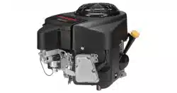
FR651V
FR691V
FR730V
4-Stroke Air-Cooled V-Twin Gasoline Engine
Motor gasolina de 4 tiempos, V-gemelo y refrigerado por aire
The engine exhaust from this product
contains chemicals known to the
State of California to cause cancer,
birth defects or other reproductive
harm.
WARNING
Para realizar reparaciones u obtener asistencia
con la garantía, póngase en contacto con su
distribuidor autorizado de motores Kawasaki
local o instalación de mantenimiento con similar
cualificación,
correo electrónico:
teléfono gratuito 1-877-364-6404
El escape del motor de este producto
contiene productos químicos que,
según el Estado de California,
provocan cáncer, defectos de
nacimiento o afectan a la fecundidad.
ADVERTENCIA
For repair / warranty assistance please contact
your local authorized Kawasaki engine dealer
or equally qualified service facility,
email: [email protected] or
call toll-free 1-877-364-6404

ENGLISH j
General-purpose Engine
Owner’s Manual
Original instructions

SAFETY AWARENESS
Whenever you see the symbols shown below,
heed their instructions! Always follow safe operat-
ing and maintenance practices.
WARNING
This warning symbol identifies special in-
structions or procedures which, if not cor-
rectly followe
d, could result in personal
injury, or loss of life.
CAUTION
This caution symbo
l identifies special in-
structions or procedures which, if not strictly
observed, could result in damage to, or de-
struction of equi
pment.
NOTE
○
This note symbol indicates points of particular in-
terest for more
efficient and convenient operation.
READ THE OPERATING INSTRUCTIONS OF THE EQUIPMENT THIS ENGINE POWERS.
© 2008 Kawasaki Heavy Industries, Ltd. (1): Dec. 2010. (M)
Sep. 2016 (1) (M)
2016

READ THIS FIRST
For your safety, read this Owner’s Manual and understand it thoroughly before operating this ENGINE.
WARNING
DO NOT run the engine in a closed area. Ex haust gas contains carbon monoxide, an odorless and
deadly poison.
Gasoline is extremely fl ammable and can be explosive under certain condition.
Stop engine and allow the engine to cool before refueling.
DO NOT smoke. Make sure area is well ventilated and free from any source of flame or sparks including
the pilot lamp of any appliance while refueling, servicing fuel system, draining gasoline and/or adjusting
carburetor.
DO NOT fill the tank so the fuel level rises into the filler neck or level surface of level gauge. If the tank is
overfilled, heat may cause the fuel to expand and overflow through the vents in the tank cap.
Wipe off an y spilled gasoline immediately.
T
o prevent fire hazard:
Keep the engine at least 1 m (3.3 ft) away from buildings, obstructions and other burnable objects.
DO NOT place flammable objects close to the engine.
DO NOT ex p lose combustible materials to the engine exhaust.
DO NOT use the engine on any forest covered, brush covered or grass covered unimproved land unless
spark arrester is installed on the muffler.
T
o avoid getting an electric shock, DO NOT touch spark plugs, p l ug caps or spark plug leads during
engine runni ng.
To avoid a serious b urn, DO NOT touch a hot engine or muffler. T h e engine becomes hot during
operation. Before you service or remove parts, stop engine and allow the engine to cool.
DO NOT plac e hands or feet near moving or rotating parts. Pla ce a protective cover over pulley, V
belt or coupling.
DO NOT run engine at excess ive speeds. This may result in injury.
Always rem o ve the s park plug caps from spark plug s when servicing the engine to prevent acci-
dental starting .
Read warning labels which are on the engine and understand them. If any label is missing, damaged, or
worn get a replacement from your Kawasaki engine dealer and install it in the correct position.
Read warning labels which are on the engine and understand them. If any label is missing, damaged, or
worn get a replacement from your authorized Kawasaki engine dealer or equally qualied service facility and
install it in the correct position.

READ THIS FIRST
For your safety, read this Owner’s Manual and understand it thoroughly before operating this ENGINE.
WARNING
DO NOT run the engine in a closed area. Exhaust gas contai ns carbo n monoxide, an odorless and
deadly poison.
Gasoline is extremely flammable and can be explosive under certain condition.
Stop engine and allow the engine to cool before refueling.
DO NOT smoke. Make sure area is well ventilated and free from any source of flame or sparks including
the pilot lamp of any appliance wh ile refueling, servicing fuel system , draining gasoline and/or adjusting
carburetor.
DO NOT fill the tank so the fuel level rises into the filler neck or level surface of level gauge. If the tank is
overfilled, heat may cause the fuel to expand and overflow through the vents in the tank cap.
Wipe off an y spilled gasoline immediately.
To prevent fire hazard:
Keep the engine at least 1 m (3.3 ft) away from buildings, obstructions and other burnable objects.
DO NOT place flammable objects close to the engine.
DO NOT ex p lose combustible materials to the engine exhaust.
DO NOT use the engine on any forest covered, brush covered or grass covered unimproved land unless
spark arrester is installed on the muffler.
To avoid getti n g an electric shock, DO NOT touch spark plugs, plug caps or spark plug leads during
engine runni ng.
To avoid a s erious b urn, DO NOT touch a hot engine or muffler. T h e engine becomes hot during
operation. Before you service or remov
e parts, stop engine and a llow the engine to co ol.
DO NOT plac e hands or fee t near mo ving or rotating parts. Pla ce a prot ective cover over pull ey, V
belt or coupling.
DO NOT run engine at exces sive speeds . This may result in injury.
Alway s remove the spark plug caps from spark plugs when servicing the engine to prevent acci-
dental starting.
Read warning labels which are on the engine and understand them. If any label is missing, damaged, or
worn get a replacement from your Kawasaki engine dealer and install it in the correct position.
EMISSION CONTROL INFORMATION
Fuel Information
THIS ENGINE IS CERTIFIED TO OPERATE ON UNLEADED REGULAR GRADE GASOLINE ONLY.
A minimum of 87 octane of the antiknock index is recommended. The antiknock index is posted on service
station pumps in the U.S.A.
Emission Control Information
To protect the environment in which we all live, Kawasaki has incorporated an exhaust emission control sys-
tem in compliance with applicable regulations of the United States Environmental Protection Agency and the
California Air Resources Board. Also, depending on when your engine was produced, it may have an assigned
emissions d urability perio d. *See b elow for the engine emissions durability period that may apply to your en-
gine.
Exhaust Emission Control System
The exhaust emission control system applied to this engine consists of a fuel system and an ignition system
having optimum ignition timing characteristics. The fuel system has been calibrated to provide lean air/fuel
mixture characteristics and optimum fuel economy with a suitable air cleaner and exhaust system.
A sealed-type crankcase emission control system is also used to eliminate blow-by gasses. The blow-by
gasses are led to a breather chamber through the crankcase and from there to the air cleaner.
Engine Emissions Compliance Period
California All Other States
Engines Greater Than or Equal To 225 cc Engines Greater Than or Equal To 225 cc
Model Year – 2008 and later Model Year – 2011 and later
Durability Period – 250 hours
Durability Period – 250 hours (Category C)
If your engine has an assigned emissions durability period it will be located on the certification label
attached to the engine (IMPORTANT ENGINE INFORMATION).

High Altitude Performance Adjustment Information
To improve the EMISSIONS CONTROL PERFORMANCE of engines operated above 1000 meters
(3300 feet), Kawasaki requires the following Environmental Protection Agency (EPA) and California Air
Resources Board (CARB) approved modications. High altitude adjustment requires replacement of carburetor
main jets. Installation of these optional parts may be performed by an authorized Kawasaki dealer, or the
consumer, following repair recommendations specied in the appropriate Kawasaki Service document or parts
catalog.
Operating with wrong conguration at an altitude may increase its emission and decrease fuel efciency and
performance.
NOTE
○When properly performed, these specied modications only are not considered to be emissions system
“tampering” and engine performance is generally unchanged as a result.
○Engine models with fuel injection do not require high altitude performance adjustment.
Maintenance and Warranty
Proper maintenance is necessary to ensure that your engine will continue to have low emission levels. This
Owner’s Manual contains those maintenance recommendations for your engine. Those items identied by the
Periodic Maintenance Chart are necessary to ensure compliance with the applicable standards.
As the owner of the engine, you have the responsibility to make sure that the recommended maintenance is
carried out according to the instructions in this Owner’s Manual at your own expense.
The Kawasaki Limited Emission Control System Warranty requires that you return your engine to an
authorized Kawasaki dealer for remedy under warranty. Please read the warranty carefully, and keep it valid by
complying with the owner’s obligations it contains.
High Altitude Performance Adjustment Information
To improve the EMISSIONS CONTROL PERFORMANCE of engines operated above 1,000 meters (3,300
feet), Kawasaki recommends the following Environmental Protection Agency (EPA) and the California Air Re-
sources Board (CARB) approved modifications.
However, the model with DFI (Digital Fuel Injection system) does not require high altitude performance ad-
justment.
NOTE
○
When properly performed, these specified modifications only are not considered to be emissions system
"tampering" and engine performance is generally unchanged as a result.
Maintenance and Warranty
Proper maintenance is necessary to ensure that your engine will continue to have low emission levels. This
Owner’s Manual contains those maintenance recommendations for your engine. Those items identified by the
Periodic Maintenance Chart are necessary to ensure compliance with the applicable standards.
As the owner of the eng ine, you have the r esponsibility to make sure that the recommended maintenance is
carried out according to the instructions in this Owner’s Manual at your own expense.
The Kawasaki Limited Emission Control Sy stem Warranty requires that you return your engine to an au tho-
rized Kawasaki dealer for remedy under warranty. Please read the warranty carefully, and keep it valid by
complying with the owner’s obligations it contains.
Tampering with Emission Control System Prohibited
Federal law and California State law prohibit the following acts or the causing thereof: (1) the removal or
rendering inoperative by any person other than for purposes of maintenance, repair, or replacement, of any
device or element of design incorporated into any new engine for the purposes of emission control prior to its
sale or delivery to the ultimate purchaser or while it is in use, or (2) the use of the engine after such device or
element of design has been removed or rendered inoperative by any person.
The Kawasaki Limited Emission Control System Warranty requires that you return your engine to an
authorized Kawasaki engine dealer or equally qualified service facility for remedy under warranty. Please
read the warranty carefully, and keep it valid by complying with the owner’s obligations it contains.

Among those acts presumed to constitute tampering are the acts listed below:
Do not t amper with the original emission rela ted parts:
•
Carburetor or DFI system, and their internal parts
•
Spark Plug
•
Magneto or electronic ignition system
•
Fuel filter element
•
Air cleaner elements
•
Crankcase
•
Cylinder heads
•
Breather chamber and internal parts
•
Intake pipe and tube
•
Muffler or any internal portion of the muffler
High Altitude Performance Adjustment Information
To improve the EMISSIONS CONTROL PERFORMANCE of engines operated above 1000 meters
(3300 feet), Kawasaki requires the following Environmental Protection Agency (EPA) and California Air
Resources Board (CARB) approved modications. High altitude adjustment requires replacement of carburetor
main jets. Installation of these optional parts may be performed by an authorized Kawasaki dealer, or the
consumer, following repair recommendations specied in the appropriate Kawasaki Service document or parts
catalog.
Operating with wrong conguration at an altitude may increase its emission and decrease fuel efciency and
performance.
NOTE
○When properly performed, these specied modications only are not considered to be emissions system
“tampering” and engine performance is generally unchanged as a result.
○Engine models with fuel injection do not require high altitude performance adjustment.
Maintenance and Warranty
Proper maintenance is necessary to ensure that your engine will continue to have low emission levels. This
Owner’s Manual contains those maintenance recommendations for your engine. Those items identied by the
Periodic Maintenance Chart are necessary to ensure compliance with the applicable standards.
As the owner of the engine, you have the responsibility to make sure that the recommended maintenance is
carried out according to the instructions in this Owner’s Manual at your own expense.
The Kawasaki Limited Emission Control System Warranty requires that you return your engine to an
authorized Kawasaki dealer for remedy under warranty. Please read the warranty carefully, and keep it valid by
complying with the owner’s obligations it contains.
High Altitude Performance Adjustment Information
To improve the EMISSIONS CONTROL PERFORMANCE of engines operated above 1,000 meters (3,300
feet), Kawasaki recommends the following Environmental Protection Agency (EPA) and the California Air Re-
sources Board (CARB) approved modifications.
However, the model with DFI (Digital Fuel Injection system) does not require high altitude performance ad-
justment.
NOTE
○
When properly performed, these specified modifications only are not considered to be emissions system
"tampering" and engine performance is generally unchanged as a result.
Maintenance and Warranty
Proper maintenance is necessary to ensure that your engine will continue to have low emission levels. This
Owner’s Manual contains those maintenance recommendations for your engine. Those items identified by the
Periodic Maintenance Chart are necessary to ensure compliance with the applicable standards.
As the owner of the eng ine, you have the r esponsibility to make sure that the recommended maintenance is
carried out according to the instructions in this Owner’s Manual at your own expense.
The Kawasaki Limited Emission Control Sy stem Warranty requires that you return your engine to an au tho-
rized Kawasaki dealer for remedy under warranty. Please read the warranty carefully, and keep it valid by
complying with the owner’s obligations it contains.
Tampering with Emission Control System Prohibited
Federal law and California State law prohibit the following acts or the causing thereof: (1) the removal or
rendering inoperative by any person other than for purposes of maintenance, repair, or replacement, of any
device or element of design incorporated into any n ew engine for the purposes of emission control prior to its
sale or delivery to the ultimate purchaser or while it is in use, or (2) the use of the engine after such device or
element of design has been removed or rendered inoperative by any person.

FOREWORD
This Owner’s Manual provided to aid you in the safe and reliable operation of your Engine. READ AND
UNDERSTAND IT THOROUGHLY BEFORE OPERATING YOUR ENGINE.
READ THE OPERATING INSTRUCTIONS OF THE EQUIPMENT THIS ENGINE POWERS.
To ensure a long, trouble-free life for your Engine, give it proper care and maintenance in accordance with
this Owner’s Manual.
Please note that the photographs and illustrations shown in this manual are made based on Model FR730V
as a typical example among other similar models.
All rights reserved. No part of this publication may be reproduced, stored in a retrieval system, or transmitted
in any form or by any means, electronic mechanical photocopying, recording or otherwise, without the prior
written permission of Kawasaki Heavy Industries, Ltd., Motorcycle & Engine Company. Although every possible
care has been taken to make this manual as complete and accurate as possible, Kawasaki cannot guarantee
against errors and omissions. Due to improvements in design and performance during production, procedures
and specifications are subject to change without prior notice. Illustrations are provided for general reference
purposes, and may differ from actual product aspects and components.
TABLE OF CONTENTS
GENERAL INFORMATION.............................. 8
Label Loc ation ............................................... 8
Parts Loc ation ............................................... 9
Tune-up S pecifications ......... ......................... 10
Engine Oil Capacity....................................... 10
FUEL AND OIL RECOMMENDATIONS .......... 11
Fuel ............................................................... 11
Engine Oil............................................ .......... 12
PREPARATION................................................ 13
Fuel ............................................................... 13
Engine Oil............................................ .......... 13
STARTING ....................................................... 15
Starting the Engine........................................ 15
OPERATING .................................................... 17
Warming Up.......................... ......................... 17
Engine Inclination .......................................... 17
STOPPING ....................................................... 18
Stopping the Engine ...................................... 18
Emergency S top............................... .......... 18
ADJUSTMENT ................................................. 19
Throttle Cable Installation, Adjustment.......... 19
Choke Cable Installation, Adjust ment ........... 19
Engine Speed Adjustment............................. 20
MAINTENANCE ................... ..................... ....... 21
Periodic Maintenance Chart ......................... 21
Oil Level Check ............................................. 23
Oil Cha nge .................................................... 24
Oil Filter Change .......................................... . 25
Air Clea ner S ervice ....................................... 26
Paper Element ........................................... 26
Spark Plug Service......... ..................... .......... 27
Fuel Filter and Fuel Pump Service ................ 28
Cooling S ystem Cleaning .......................... .... 29
STORAGE. ..................... .................................. 30
Fuel System Draining .................................... 30
TROUBLESHOOTING GUIDE............... .......... 32
ENVIRONMENTAL PROTECTION.................. 34
SPECIFICATIONS............................................ 35
WIRING DIAGRAM .......................................... 36
Wiring Diagram.............................................. 36
10
10
11
12
12
13
13
14
15
15
15
17
17
19
19
19
20
20
20
21
21
21
22
23
23
25
26
27
28
28
29
30
31
32
32
34
36
37
38
38
8 GENERAL INFORMATION
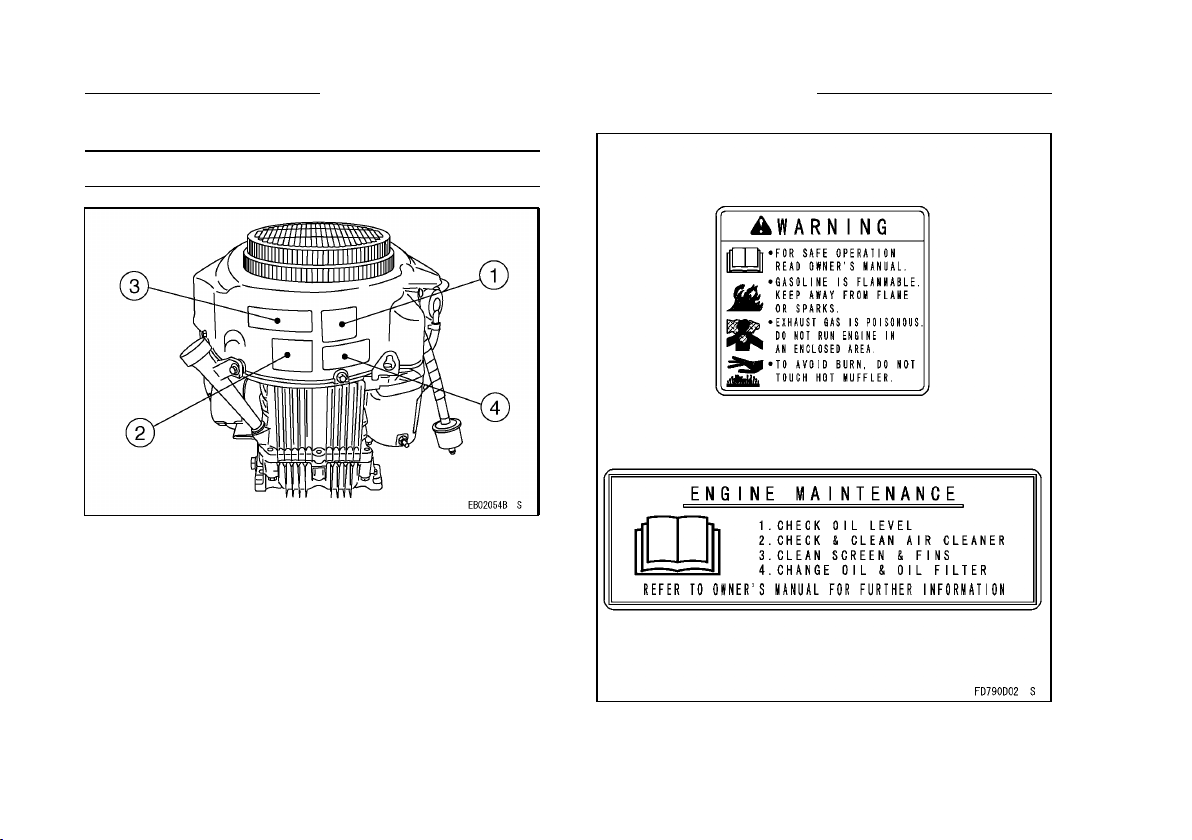
GENERAL INFORMATION
Label Location
1. Warning Label
2. Important Engine Information Label
3. Engine Mainte nance L abel
4. Engine Serial Number Label
The engine serial number is your only means of
identifying your particular engine from others of the
same model type.
This engine serial number is needed by your
dealer when ordering parts.
10
GENERAL INFORMATION
8 GENERAL INFORMATION
GENERAL INFORMATION
Label Location
1. Warning Label
2. Important Engine Information Label
3. Engine Mainte nance L abel
4. Engine Serial Number Label
The engine serial number is your only means of
identifying your particular engine from others of the
same model type.
This engine serial number is needed by your
dealer when ordering parts.
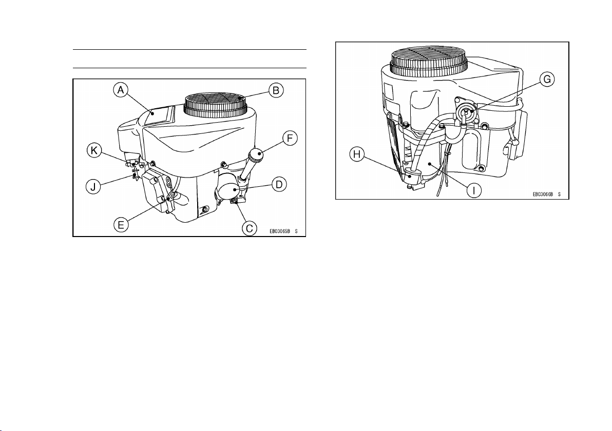
GENERAL INFORMATION 9
Parts Location
A. Air Cleaner
B. Air Inlet Guard
C. Oil Drain Plug
D. Oil Filter
E. Spark Plugs/Spark Plug Caps
F. Oil Gauge
J. Control Panel
K. Carburetor
G. Fuel Pump
H. Fuel Filter
I. Electric Starter
11
GENERAL INFORMATION
10 GENERAL INFORMATION
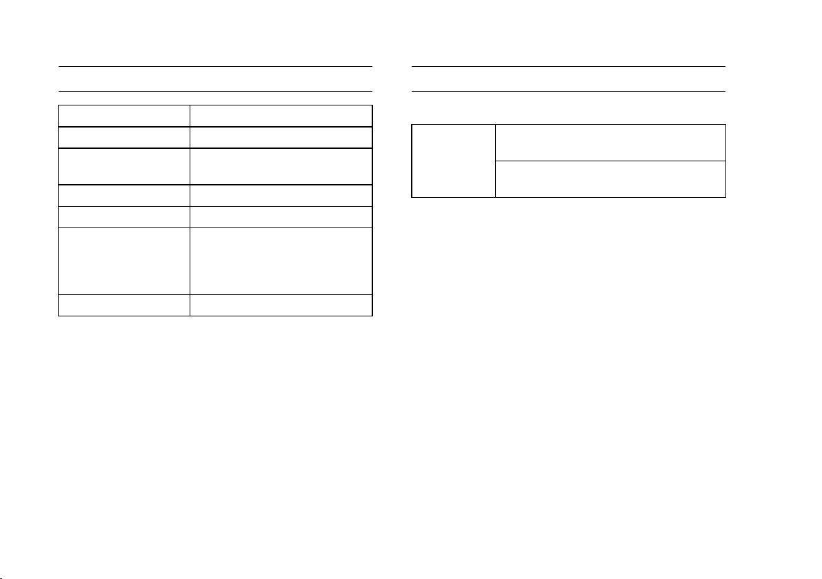
Tune-up Specifications
ITEM
Specifications
Ignition Timing Unadjustable
Spark Plugs:
Gap
NGK BPR4ES
0.75 mm (0.030 in)
Low Idle Speed 1550r/min(rpm)
High Idle Speed 3600r/min(rpm)
Valve Clearance
In 0.10 ∼ 0.15 mm
(0.004 ∼ 0.006 in)
Ex 0.10 ∼ 0.15 mm
(0.004 ∼ 0.006 in)
Other Specifications
No other adjustment needed
NOTE
○
High and low idle speeds may vary depending on
the equipment on which the engine is used. Refer
to the equipment specification.
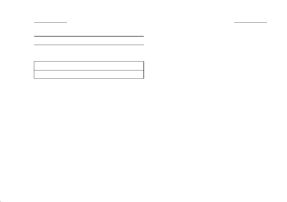
Engine Oil Capacity
Engine Oil Capacity
1.8 L (1.9 US·qt)
[when oil filter is not removed]
FR651V
FR691V
FR730V
2.1 L (2.2 US·qt)
[when oil filter is removed]
12
GENERAL INFORMATION
10 GENERAL INFORMATION
Tune-up Specifications
ITEM
Specifications
Ignition Timing Unadjustable
Spark Plugs:
Gap
NGK BPR4ES
0.75 mm (0.030 in)
Low Idle Speed 1550r/min(rpm)
High Idle Speed 3600r/min(rpm)
Valve Clearance
In 0.10 ∼ 0.15 mm
(0.004 ∼ 0.006 in)
Ex 0.10 ∼ 0.15 mm
(0.004 ∼ 0.006 in)
Other Specifications
No other adjustment needed
NOTE
○
High and low idle speeds may vary depending on
the equipment on which the engine is used. Refer
to the equipment specification.
Engine Oil Capacity
Engine Oil Capacity
1.8 L (1.9 US·qt)
[when oil filter is not removed]
FR651V
FR691V
FR730V
2.1 L (2.2 US·qt)
[when oil filter is removed]
FUEL AND OIL RECOMMENDATIONS 11
FUEL AND OIL RECOMMENDATIONS
Fuel
Use only clean, fresh, unleaded regular grade
gasoline.
CAUTION
Do not mix oil with gasoline.
Octane Rating
The octane rating of a gasoline is a measure of
its resistance to “knocking”. Using a minimum of 87
octane by the antiknock index is recommended. The
antiknock index is posted on service station pumps
in the U.S.A.
Antikn ock Inde x: (RON + MON)/2
RON = Research Octane Number
MON = Motor Octane Number
NOTE
○
If “knocking or pinging” occurs, use a different
brand of gasoline or higher octane rating.
Oxygenated Fuel
Oxygenates (either ethanol or MTBE) are added
to the gasoline. If you use the oxygenated fuel be
sure it is unleaded and meets the minimum octane
rating requirement.
The following are the EPA approved percentages
of fuel oxygenates.
ETHANOL: (Ethyl or Grain Alcohol)
You may use gasoline containing up to 10%
ethanol by volume.
MTBE: (Methyl Tertiary Butyl Ether)
You may use gasoline containing up to 15% MTBE
by volume.
METHANOL: (Methyl or Wood Alcohol) 5% by vol-
ume
You may use gasoline containing up to 5%
methanol by volume, as long as it also contains
cosolvents and corrosion inhibitors to protect the
fuel system. Gasoline containing more than 5%
methanol by volume may cause starting and/or
performance problems. It may also damage metal,
rubber, and plastic parts of your fuel sys tem.
13
FUEL AND OIL RECOMMENDATIONS
12 FUEL AND OIL RECOMMENDATIONS
Engine Oil
The following engine oils are recommended.
API Service Classification : SF, SG, SH, SJ or SL.
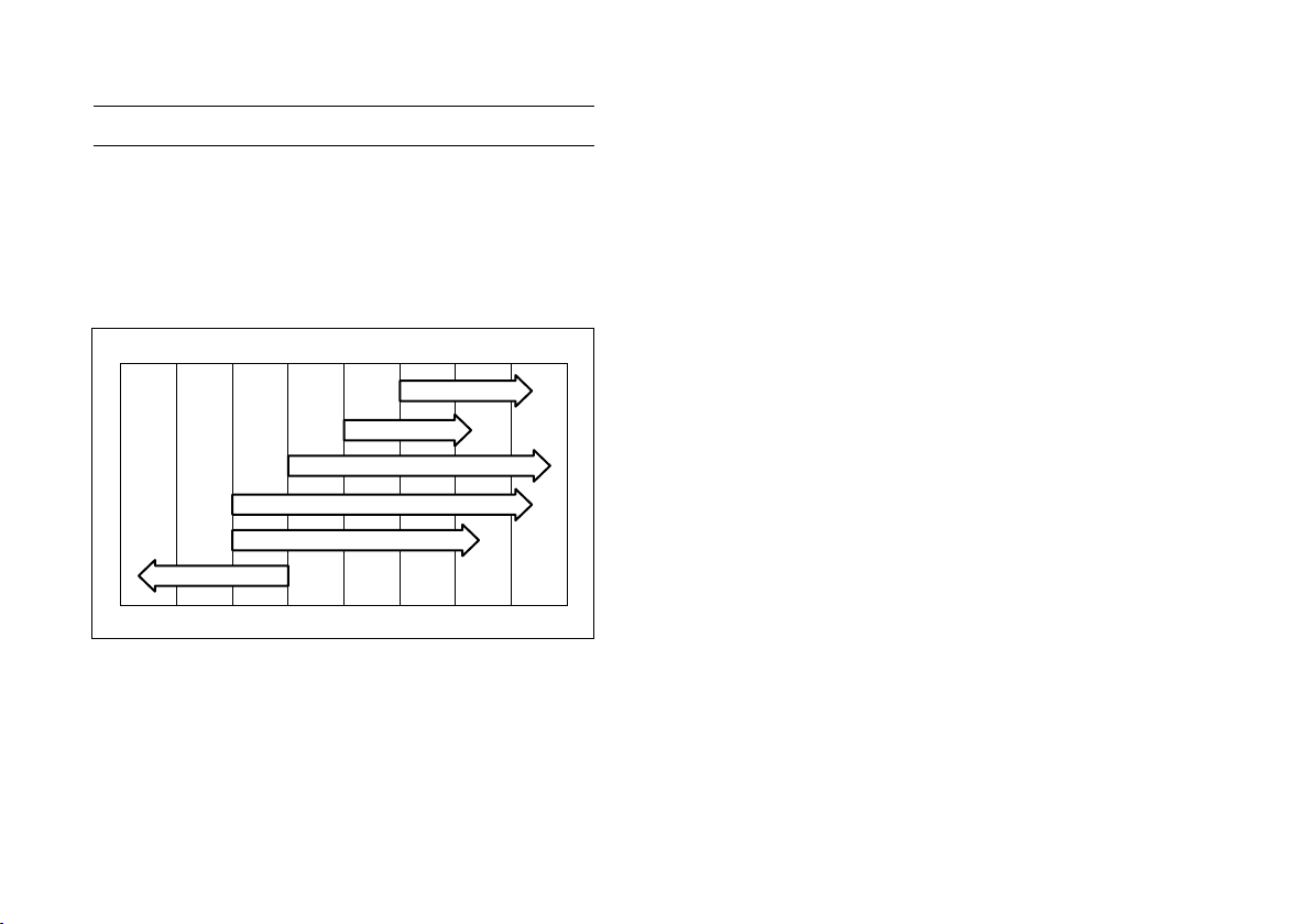
Oil Viscosity
Choose the viscosity according to the temperature
as follows :
NOTE
○
Using multi grade oils (5W-20, 10W-30, and 10W
-40) will increase oil consumption. Check oil level
more frequently when using them.
FUEL AND OIL RECOMMENDATIONS 13
Engine Oil
The following engine oils are recommended.
API Service Classication: SF, SG, SH, SJ or SL.
Oil Viscosity
Choose the viscosity according to the temperature
as follows:
-20ºC -10ºC 0ºC 10ºC 20ºC 30ºC 40ºC
-4ºF 14ºF 32ºF 50ºF 68ºF 86ºF 104ºF
SAE20W-50
SAE5W-20
SAE10W-40
SAE10W-30
SAE5W-20
SAE30
SAE40
NOTE
○Although 10W-40 engine oil is the recommended
oil for most conditions, the oil viscosity may need
to be changed to accommodate atmospheric
conditions. Using 20W-50 oil in higher ambient
temperatures may reduce oil consumption.
14
FUEL AND OIL RECOMMENDATIONS
PREPARATION 13
PREPARATION
Fuel
WARNING
Gasoline is extremely flammable and can be
explosive under certain conditions.
Before refueling, turn the engine switch to
“OFF” position. Do not smoke. Make sure
the area is well ventilated and free from any
source of flame or sparks, including any ap-
pliances with a pilot lamp.
Never fill tank so that fuel level rises into
the filler neck. If tank is overfilled, heat may
cause fuel to expand and overflow through
vents in tank cap.
After refueling make sure tank cap is se-
curely closed.
If gasoline is spilled, wipe it up immediately.
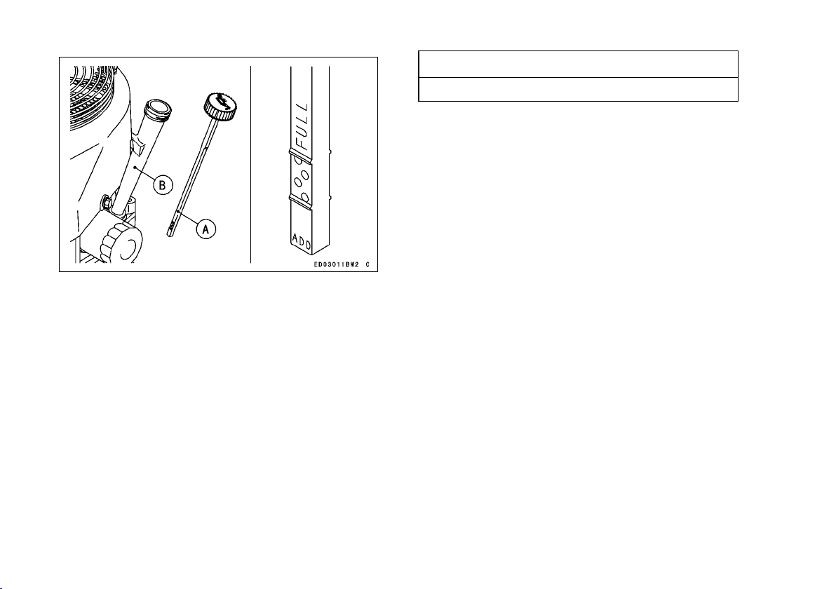
Engine Oil
Check the engine oil daily before starting the en-
gine otherwise shortage of the engine oil may cause
serious damage to the engine such as seizure.
•
Place the engine on level surface. Clean area
around the oil gauge before removing it.
•
Remove the oil gauge (A) and wipe it with a clean
cloth.
•
Pour the oil slowly to “FULL” mark on the oil gauge.
•
Insert the oil gauge into tube (B) WITHOUT
SCREWING IT IN.
•
Remove the oil gauge (A) to check the oil level.
The level should be between “ADD” and “FULL”
marks. Do not overfill.
•
Install and tighten the oil gauge (A).
CAUTION
Do not fill above the “FULL” mark. Excess
oil will cause a smoking condition, and may
cause the engine to overheat.
Engine Oil Capacity
1.8 L (1.9 US·qt)
[when oil filter is not removed]
FR651V
FR691V
FR730V
2.1 L (2.2 US·qt)
[when oil filter is removed]
15
PREPARATION
14 PREPARATION
A. Oil Gauge
B. Tube
CAUTION
The engine is shipped without engine oil.
16
PREPARATION
14 PREPARATION
A. Oil Gauge
B. Tube
CAUTION
The engine is shipped without engine oil.
STARTING 15
STARTING
Starting the Engine
WARNING
Exhaust gases contain carbon monoxide, a
colorless, odorless, poisonous gas.
Do not operate the unit in enclosed areas.
Provide adequate ventilation at all times.
WARNING
Engine exhaust may ignite combustible ma-
terials and cause a fire.
Keep the area around the exhaust outlet
clear. Locate the unit so that the exhaust
outlet points toward an open area and is
located at least one meter (3.3 feet) from any
obstructions.
NOTE
○
Be aware of the following in order to start the en-
gine easily in cold weather.
○
Use proper oil for expected temperature (See
“FUEL AND OIL RECOMMENDATIONS” chap-
ter).
Use fresh gasoline.
Protect the engine or the e quipment from direct
exposure to weather when not in operation.
NOTE
○
Follow the operating instructions of the equipment
this engine powers.
•
Before starting the engine, disconnect all possible
external loads.
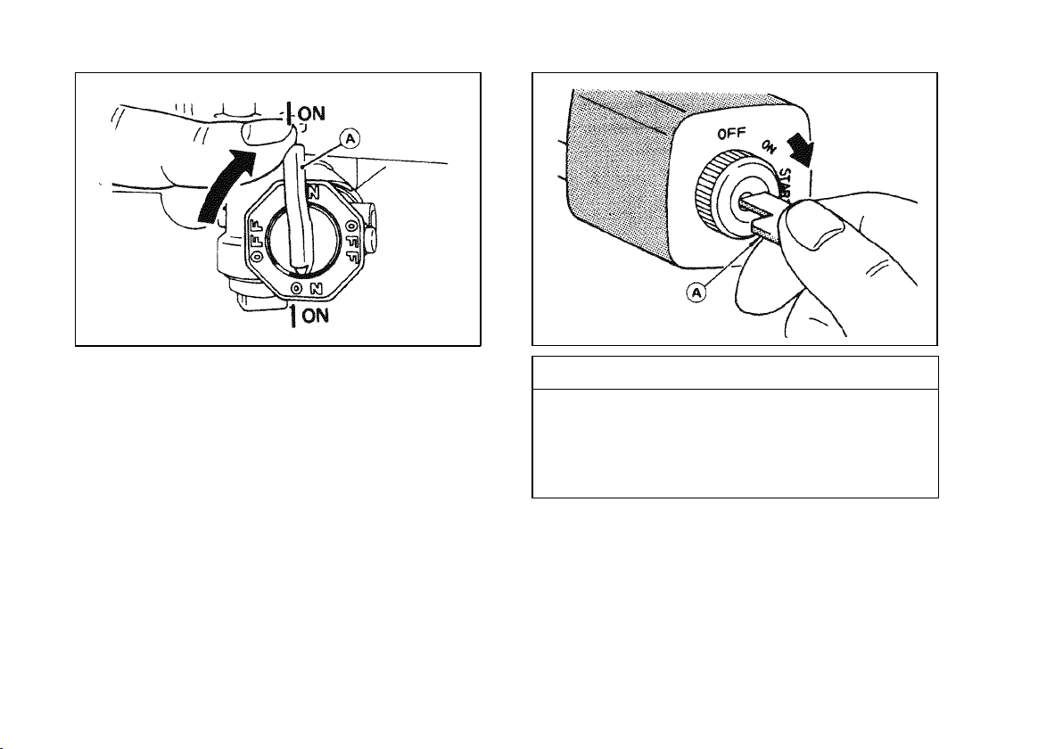
Open the fuel valve (A) on the equipment.
Move throttle lever on dash to half throttle position.
Use full choke w
hen the engine is c old, but in hot
weather or w
hen the engine is already warm, use
half choke or leave the choke fully open.
Put the switch key into the engine switch.
Turn the switch key to the START position on the
equipment. Usually engine will start within 3 sec-
onds.
CAUTION
Do not run the electric starter continuously
for more than 5 seconds, otherwise the bat-
tery may discharge quickly. If the engine
does not start right away, wait 15 seconds
and try again.
NOTE
○
When the engine is very warm, or when the engine
does not start immediately, DO NOT keep trying
to start it with the choke closed as this will cause
flooding and make starting more difficult.
○
Instead, fully open the choke and start the engine.
17
STARTING
16 STARTING
CAUTION
Whenever you start engine, make sure warn-
ing lamp is not illuminated after engine
starts. If warning lamp comes on, stop
engine immediately and check oil level (If
equipped).
•
After starting the engine, gradually return the
choke lever to the fully open position.
18
STARTING
16 STARTING
CAUTION
Whenever you start engine, make sure warn-
ing lamp is not illuminated after engine
starts. If warning lamp comes on, stop
engine immediately and check oil level (If
equipped).
•
After starting the engine, gradually return the
choke lever to the fully open position.
OPERATING 17
OPERATING
Warming Up
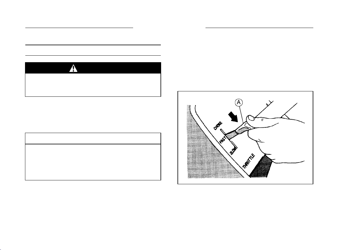
After the engine starts, move the throttle lever (A)
on the equipment to halfway between “FAST” and
“SLOW”.
To warm up the engine, run it for 3 to 5 minutes
with the throttle lever in the same load position
(halfway) before putting the equipment under load.
Then, move the throttle lever (A) on the equipment
to its “FAST” position.
CAUTION
Allow engine to warm up sufficiently (3 to 5
minutes at idle) before applying a load. This
will allow oil to reach all engine parts, and
allow piston clearance to reach design spec-
ifications.
CAUTION
While warming up the engine, make sure the
warning lamp (oil pressure) on dash is not
on. The warning lamp must not be illumi-
nated during engine operation (if equipped).
Engine Inclination
This engine will operate continuously at angles up
to 25° in any direction.
Refer to the operating instructions of the equip-
ment this engine powers. Because of equipment
design or application, there may be more stringent
restrictions regarding the angle of operation.
CAUTION
Do not operate this engine continuously at
angles exceeding 25° in any direction. En-
gine damage could result from insufficient
lubrication.
19
OPERATING
18 STOPPING
STOPPING
Stopping the Engine
WARNING
Always remove Engine Key from switch
when leaving equipment unattended or
when equipment is not in use.
Ordinary Stop
•
Move the throttle lever (A) to “slow” position.
•
Lower the engine speed to the idle speed. Keep
running at the idle speed for about one minute.
CAUTION
Engine damage can occur from run-on or
after-burning if engine is stopped suddenly
from high speed loaded operation. Reduce
engine speed to idle for one minute before
shutting engine off.
•
Turn the engine switch or the switch key to “OFF”
position.
For Contr ol Panel S witch Type, move the thro ttl e
lever against its low speed end to turn the ignition
off.
Emergency Stop
•
Immediately turn the engine switch or the switch
key to “OFF” position.
Close the fuel valve on the equipment.
For Control Panel Switch Type, move the throttle
lever on the equipment to its low speed end. Moving
the lever to its low speed end turns ignition off.
20
STOPPING

18 STOPPING
STOPPING
Stopping the Engine
WARNING
Always remove Engine Key from switch
when leaving equipment unattended or
when equipment is not in use.
Ordinary Stop
•
Move the throttle lever (A) to “slow” position.
•
Lower the engine speed to the idle speed. Keep
running at the idle speed for about one minute.
CAUTION
Engine damage can occur from run-on or
after-burning if engine is stopped suddenly
from high speed loaded operation. Reduce
engine speed to idle for one minute before
shutting engine off.
•
Turn the engine switch or the switch key to “OFF”
position.
For Contr ol Panel S witch Type, move the thro ttl e
lever against its low speed end to turn the ignition
off.
Emergency Stop
•
Immediately turn the engine switch or the switch
key to “OFF” position.
Close the fuel valve on the equipment.
For Control Panel Switch Type, move the throttle
lever on the equipment to its low speed end. Moving
the lever to its low speed end turns ignition off.
ADJUSTMENT 19
ADJUSTMENT
Throttle Cable Installation, Adjustment
•
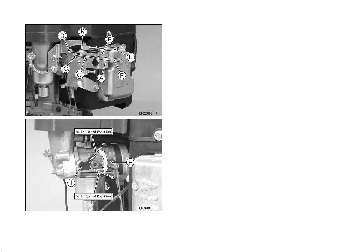
Link the throttle cable (G) to the speed control
lever (C) and loosely clamp the throttle cable outer
housing (F) with the cable clamp bolt (A).
Move the throttle lever to “FAST” position.
Pull up the outer housing (F) of the throttle cable
until the inner wire (G) has almost no slack, and
tighten the cable clamp bolt (A).
Move the throttle lever to “SLOW” position. Make
sure that the carburetor throttle valve (H) is moved
smoothly.
Choke Cable Installation, Adjustment
•
Link the choke cable (K) to the choke cont rol lever
(D), and loosely clamp the choke cable outer
housing (L) with the cable clamp bolt (B).
Move the equipment choke control to “OPEN” po-
sition. Make sure that the carburetor choke valve
(I) is fully opened.
Pull up the outer housing (L) of the choke cable
until the inner wire (K) has almost no slack, and
tighten the cable clamp bolt (B).
Move the equipment choke control to “CHOKE”
position. Make sure that the carburetor choke
valve (I) is completely closed.
Make sure that the choke valve turns from fully
closed position to fully opened position when ac-
tuating the equipment choke control.
21
ADJUSTMENT
20 ADJUSTMENT
Engine Speed Adjustment
NOTE
○
Do not tamper with the governor setting or the car-
buretor setting to increase the engine speed. Ev-
ery carburetor is adjusted at the factory and a cap
or stop plate is installed on each mixture screw.
○
If any adjustment is necessary, it must be per-
formed by your authorized Kawasaki Engine
dealer.
If any adjustment is necessary, it must be per-
formed by your authorized Kawasaki engine
dealer or equally qualied service facility.
22
ADJUSTMENT
20 ADJUSTMENT
Engine Speed Adjustment
NOTE
○
Do not tamper with the governor setting or the car-
buretor setting to increase the engine speed. Ev-
ery carburetor is adjusted at the factory and a cap
or stop plate is installed on each mixture screw.
○
If any adjustment is necessary, it must be per-
formed by your authorized Kawasaki Engine
dealer.
MAINTENANCE 21
MAINTENANCE
Maintenance, replacement, or repair of the emission control devices and systems may be performed
by any nonroad engine repair establishment or individual.
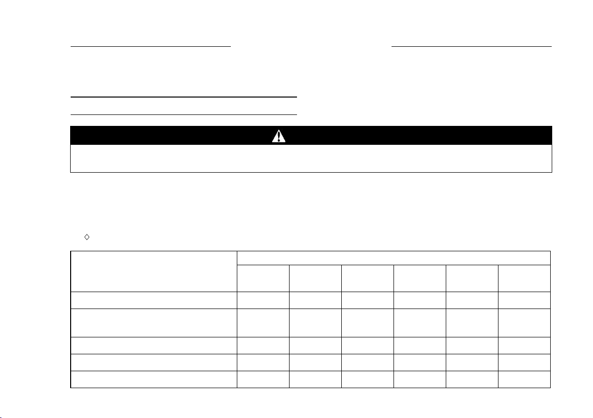
Periodic Maintenance Chart
WARNING
Always remove the spark plug caps from spark plugs when servicing the engine to prevent acci-
dental starting.
NOTE
○
The service intervals can be used as a guide. Service more frequently as necessary by operating conditions.
♦ : Service more frequently under dusty conditions.
K:Service to be performed by a n authorized K aw as a ki dealer.
INTERVAL
MAINTENANCE
Daily
First
8 hr.
Every
25 hr.
Every
50 hr.
Every
100 hr.
Every
200 hr.
Every
250 hr.
Every
300 hr.
Every
500 hr.
Check and add engine oil.
•
Check for loose or lost nuts and
screws.
•
Check for fuel and oil leakage.
•
Check battery electrolyte level.
•
♦
Check or clean air inlet screen.
•
Service to be performed by an authorized Kawasaki engine dealer or equally qualied service facility.
MAINTENANCE
INTERVAL
Daily
Every
100 hr.
Every
200 hr.
Every
250 hr.
Every
300 hr.
Every
500 hr.
Check and add engine oil.
●
Check for loose or lost nuts and
screws.
●
Check for fuel and oil leakage.
●
Check battery electrolyte level.
●
◆
Check or clean air inlet screen.
●
23
MAINTENANCE
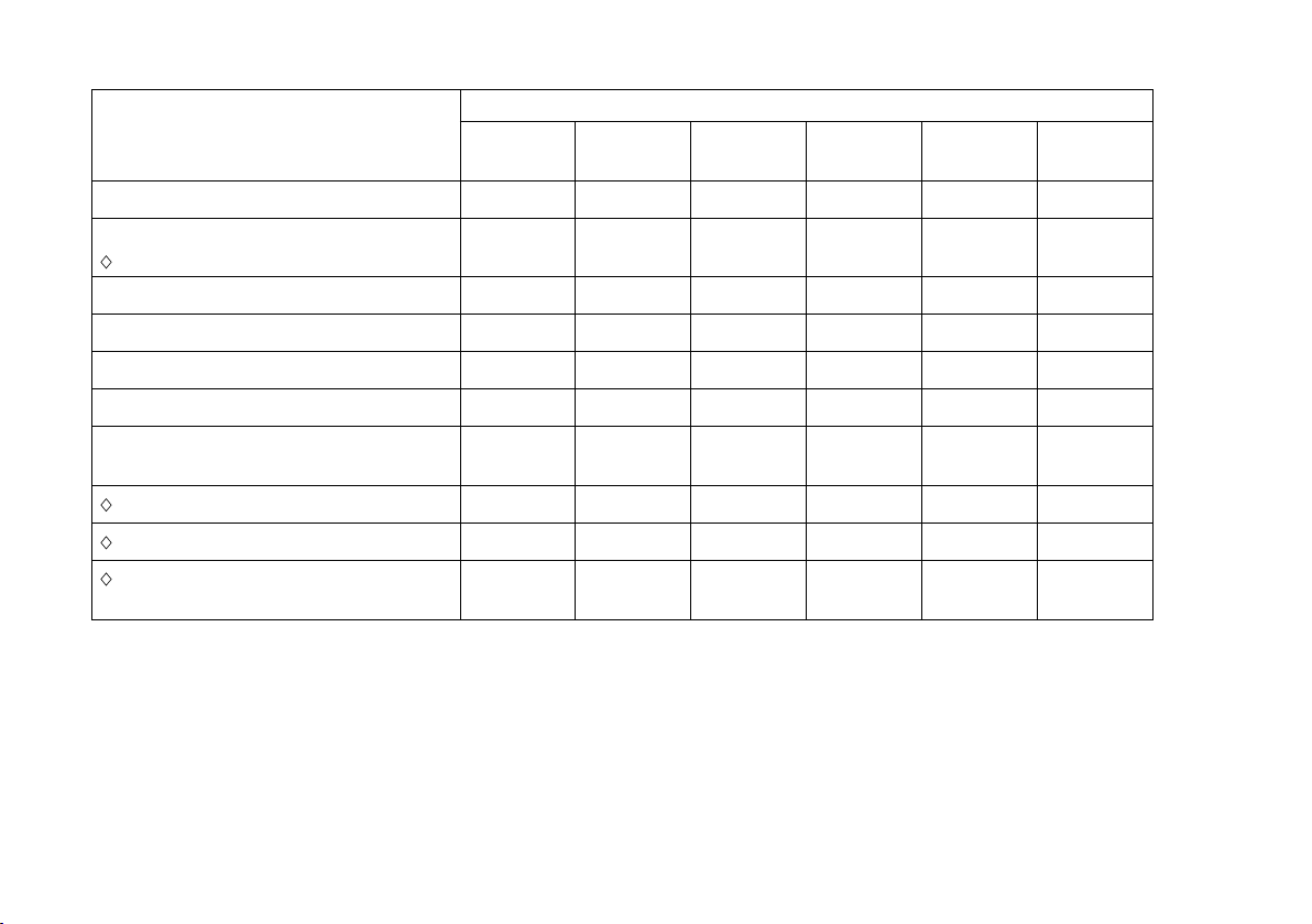
MAINTENANCE
INTERVAL
Daily
Every
100 hr.
Every
200 hr.
Every
250 hr.
Every
300 hr.
Every
500 hr.
◆
Clean air cleaner paper element.
●
◆
Clean dust and dirt from cylinder
and cylinder head ns.
●
Tighten nuts and screws.
●
Change engine oil.
●
Clean and regap spark plugs.
●
Change oil lter.
●
◆
Replace air cleaner paper
element.
●
Clean combustion chamber.
●
Check and adjust valve clearance.
●
Clean and lap valve seating
surface.
●
24
MAINTENANCE

MAINTENANCE 23
Oil Level Check
Check oil level daily and before each time of oper-
ation. Be sure oil level is maintained. See “PREPA-
RATION” chapter.
Engine Oil Capacity
1.8 L (1.9 US·qt)
[when oil filter is not removed]
FR651V
FR691V
FR730V
2.1 L (2.2 US·qt)
[when oil filter is removed]
25
MAINTENANCE
24 MAINTENANCE
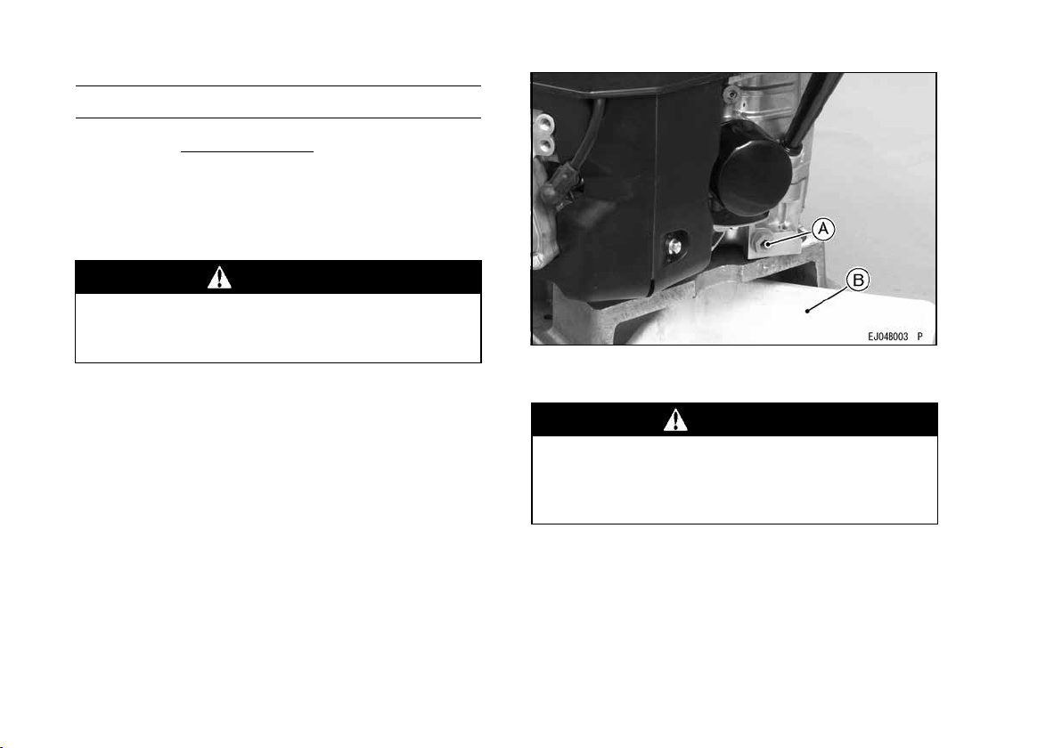
Oil Change
Change oil after first 8 hours of operation. There-
after change oil e
very 100 hours.
•
Run the engine to warm oil.
Be sure the engine (equipment) is level.
Stop the engine.
Remove the oil drain plugs (A) and drain the oil
into suitable container while engine is warm.
WARNING
Hot engine oil can cause severe burns.
Allow engine temperature to drop from hot to
warm level before draining and handling oil.
•
Install the oil drain plugs.
Remove oil gauge and refill with fresh oil (See
“FUEL AND OIL RECOMMENDATIONS” chap-
ter).
Check the oil level (See “PREPARATION” chapter
for oil level check).
A. Oil Drain Plug
B. Suitable Container
WARNING
Engine oil is a toxic substance. Dispose of
used oil properly. Contact your local author-
ities for approved disposal methods or pos-
sible recycling.
Change oil every 100 hours.
24 MAINTENANCE
Oil Change
Change oil after first 8 hours of operation . There-
after change oil e
very 100 hours.
•
Run the engine to warm oil.
Be sure the engine (equipment) is level.
Stop the engine.
Remove the oil drain plugs (A) and drain the oil
into suitable container while engine is warm.
WARNING
Hot engine oil can cause severe burns.
Allow engine temperature to drop from hot to
warm level before draining and handling oil.
•
Install the oil drain plugs.
Remove oil gauge and refill with fresh oil (See
“FUEL AND OIL RECOMMENDATIONS” chap-
ter).
Check the oil level (See “PREPARATION” chapter
for oil level check).
A. Oil Drain Plug
B. Suitable Container
WARNING
Engine oil is a toxic substance. Dispose of
used oil properly. Contact your local author-
ities for approved disposal methods or pos-
sible recycling.
26
MAINTENANCE
24 MAINTENANCE
Oil Change
Change oil after first 8 hours of operation . There-
after change oil every 100 hours.
•
Run the engine to warm oil.
Be sure the engine (equipment) is level.
Stop the engine.
Remove the oil drain plugs (A) and drain the oil
into suitable container while engine is warm.
WARNING
Hot engine oil can cause severe burns.
Allow engine temperature to drop from hot to
warm level before draining and handling oil.
•
Install the oil drain plugs.
Remove oil gauge and refill with fresh oil (See
“FUEL AND OIL RECOMMENDATIONS” chap-
ter).
Check the oil level (See “PREPARATION” chapter
for oil level check).
A. Oil Drain Plug
B. Suitable Container
WARNING
Engine oil is a toxic substance. Dispose of
used oil properly. Contact your local author-
ities for approved disposal methods or pos-
sible recycling.
MAINTENANCE 25
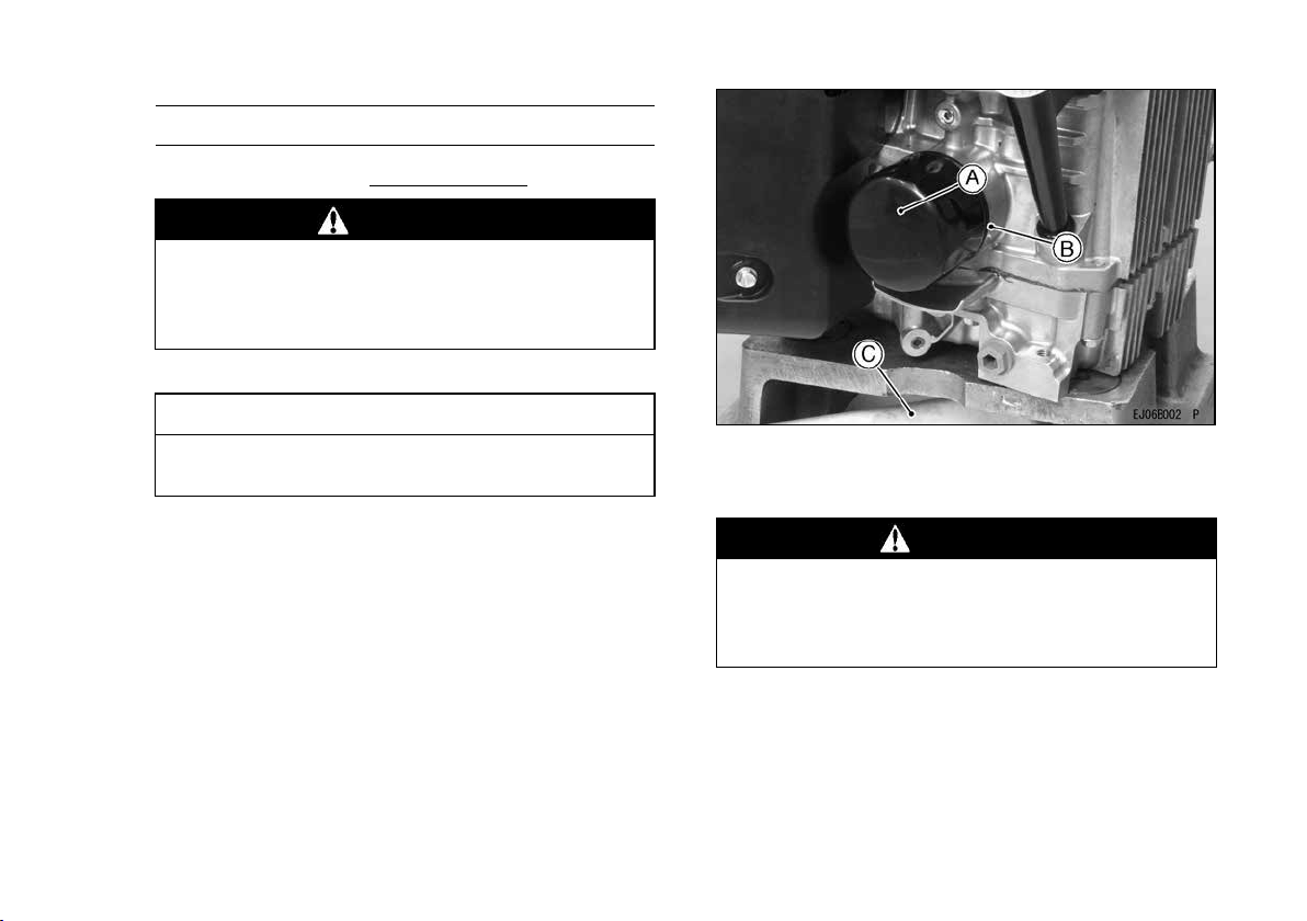
Oil Filter Change
•
Change the oil filter ev e ry 200 hours of operation.
WARNING
Hot engine oil can cause severe burns.
Allow engine temperature to drop from hot to
warm level before attempting to remove oil
filter.
•
Drain engine oil into a suitable container (C).
CAUTION
Before removing th e oil filter, place suitable
pan under filter connection.
•
Rotate the oil filter (A) counterclockwise to remove
it.
Coat a film of clean engine oil on seal of new filter.
Install new filter rotating it clockwise until seal con-
tacts mounting surface (B). Then rotate filter 3/4
turn more by hand.
Supply engine oil as specified.
Run the engine for about 3 minutes, stop engine,
and check oil leakage around the filter.
Add oil to compensate for oil level drop due to oil
filter capacity (See “PR EPARATION” chapter for
oil lev el check).
A. Oil Filter
B. Mounting Surface
C. Suitable Container
WARNING
Engine oil is a toxic substance. Dispose of
used oil properly. Contact your local author-
ities for approved disposal methods or pos-
sible recycling.
27
MAINTENANCE
26 MAINTENANCE
Air Cleaner Service
CAUTION
To prevent excessive engine wear, do not run
the engine with the air cleaner removed.
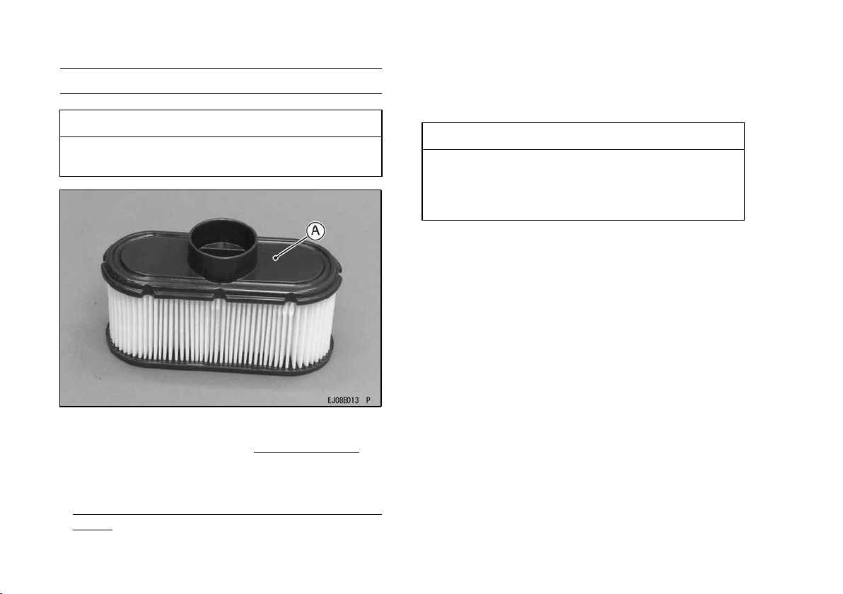
Paper Element
Clean the paper element (A) every 100 hours.
•
Clean the paper element by tapping gently to re-
move dust. If very dirty, replace the paper element
with a new one.
R
eplace with a new paper element ye a rly or 200
hours. Whichever comes first.
NOTE
○
Operating in dusty condition may require more fre-
quent maintenance than above.
CAUTION
Do not wash paper element.
Do not oil paper element.
Do not use pressurized air to clean paper el-
ement.
28
MAINTENANCE
26 MAINTENANCE
Air Cleaner Service
CAUTION
To prevent excessive engine wear, do not run
the engine with the air cleaner removed.
Paper Element
Clean the paper element (A) every 100 hours.
•
Clean the paper element by tapping gently to re-
move dust. If very dirty, replace the paper element
with a new one.
Replace with a new paper element yearly or 200
hours. Whichever comes first.
NOTE
○
Operating in dusty condition may require more fre-
quent maintenance than above.
CAUTION
Do not wash paper element.
Do not oil paper element.
Do not use pressurized air to clean paper el-
ement.
MAINTENANCE 27
Spark Plug Service
WARNING
Hot engine components can cause severe
burns.
Stop engine and allow it to cool before check-
ing spark plugs.
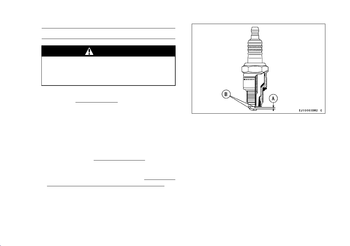
Clean or replace the spark plugs and reset spark
plug gap (A) e
very 100 hours of operation.
•
Disconnect the spark plug caps from the spark
plugs and remove the spark plugs.
Clean the electrodes (B) by scraping with a wire
brush to remove carbon de posits.
Inspect for cracked porcelain or other wear and
damage. Replace the spark plug with a new one
if necessary.
Check the spark plug gap and reset if necessary.
The gap must be 0
.75 m m (0.0 3 0 in). To change
the gap, bend only the side–electrode, using a
spark plug tool.
Install and tighten the spark plugs to 2
2 N·m (2.2
kgf·m, 16 ft·lb). Connect the spa rk plug caps.
RECOMMENDED SPARK PLUG
NGK ..................................BPR4ES
A. Spark Plug Gap
B. Electrodes
29
MAINTENANCE
28 MAINTENANCE
Fuel Filter and Fuel Pump Service
WARNING
Improper use of solvents can result in fire or
an explosion.
Do not use gasoline or low flash-point sol-
vents to clean the fuel filter and/or the fuel
pump.
Clean only in a well ventilated area away from
sources of sparks or flame, including any ap-
pliances with a pilot lamp.
•
The fuel filter can not be disassembled. If the fuel
filter gets clogged, replace it with a new one.
The fuel pump can not be disassembled. If the fuel
pump fails, r eplace it with a new one.
30
MAINTENANCE
MAINTENANCE 29
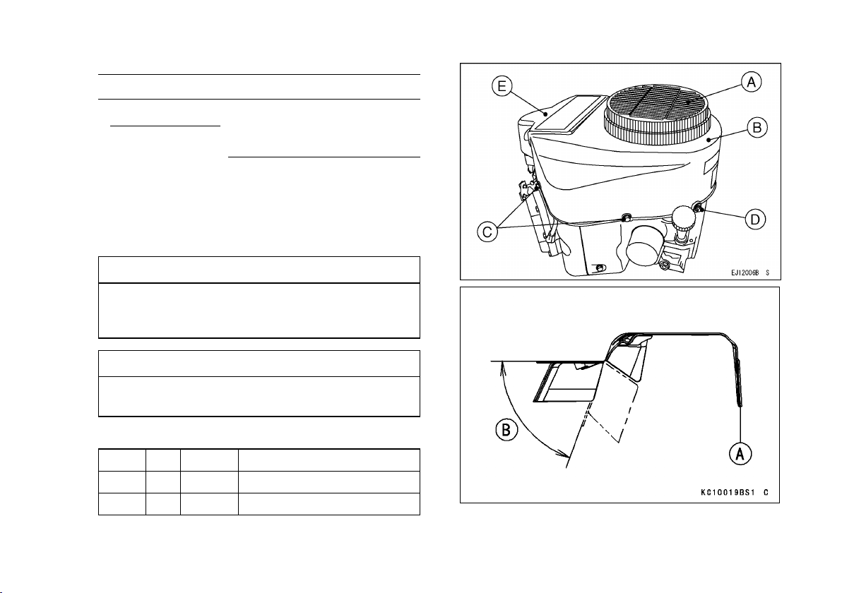
Cooling System Cleaning
Before each use, check that the air inlet (rotary)
screen (inside A) is free from grass and debris and
clean if necessary. E
very 100 hours of operation,
check and clean the cooling fins and inside of en-
gine shrouds to remove grass, chaff or dirt clogging
the cooling system and causing overheating. When
cleaning, remove the air cleaner (inside E) loosen
the bolts (C), (D), and then, remove the fan housing
(B).
CAUTION
Do not run engine before all cooling system
parts are reinstalled to keep cooling and car-
buretion as intended.
CAUTION
Bend the engine shroud (regulator side) [A]
only within the shown range [B] (70°).
[Bolts Size, Tightening Torque]
Bolts
Size
Length Tightening Torque
C
M6 16 mm
8.8 N·m (0.9 kgf·m, 78 in·lb)
D M6 22 mm
8.8 N·m (0.9 kgf·m, 78 in·lb)
[B] = 70°
31
MAINTENANCE
30 STORAGE
STORAGE
Fuel System Draining
Engines to be stored over 30 days should be com-
pletely drained of fuel to prevent gum deposits form-
ing on essential carburetor parts, fuel filter and fuel
tank.
WARNING
Gasoline is extremely flammable and can be
explosive under certain conditions.
Drain fuel before storing the equipment for
extended periods.
Drain fuel in a well-ventilated area away from
any source of flame or sparks, including any
appliances with a pilot lamp. Store fuel in an
approved container in safe location.
•
Clean every part of the engine.
Be sure that the engine switch or switch key is
positioned at “OFF”.
Close the fuel valve and remove the sediment
bowl.
Put a pan under the fuel valve to receive the
drained fuel, and open the fuel valve to drain the
fuel from fuel tank completely.
•
Install the sediment bowl and open the fuel valve.
•
To remove the fuel from the carburetor, run the
engine to use up the fuel in the carburetor.
•
Remove the spark plugs and pour approx. 1 ∼ 2
mL (0.06 ∼ 0.1 cu. in.) of engine oil through the
spark plug holes (A) and then screw the spark
plugs in after turning the engine a few times.
Slowly turn the engine until you feel compression
and then leave it there. This blocks the air inside
the cylinder and prevents rust inside the engine.
Wipe the body with oily cloth.
Wrap the engine w ith plastic sheeting and store it
in a dry place.
Change engine oil for next use after period of stor-
age (refer to “Oil Change” section in “MAINTE-
NANCE” chapter).
WARNING
Gasoline is a toxic substance. Dispose of
gasoline properly. Contact your local author-
ities for approved disposal methods.
34 STORAGE
STORAGE
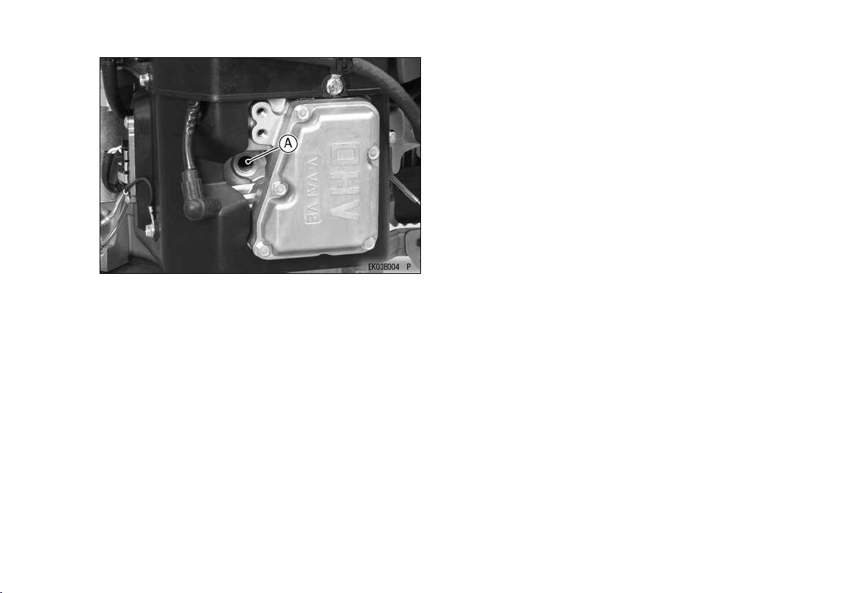
Engine Storage Procedure
When not operating your Kawasaki engine more
than 30 days, add fuel stabilizer to fuel tank and run
engine for 5 minutes then drain the fuel tank.
After drain the fuel tank, run the engine at low idle
until engine stalled.
WARNING
Gasoline is extremely ammable and can be
explosive under certain conditions.
Drain fuel before storing the equipment for
extended periods.
Drain gasoline in a well ventilated area away
from any source of ame or sparks, including
any appliances with a pilot light. Store
gasoline in an approved container in safe
location.
●Clean every part of the engine.
●Be sure that the engine switch or switch key is
positioned at “OFF” position.
●Close the fuel valve and remove the sediment
bowl.
●Put a pan under the fuel valve to receive the
drained gasoline and open the fuel valve to drain
the gasoline from fuel tank completely.
●Install the sediment bowl.
●Put a pan under the carburetor and loosen the
drain screw of the carburetor to drain the gasoline
completely.
●Tighten the drain screw.
A
A. Fuel Drain Screw
WARNING
Gasoline is a toxic substance. Dispose of
gasoline properly. Contact your local
authorities for approved disposal methods.
30 STORAGE
STORAGE
Fuel System Draining
Engines to be stored over 30 days should be com-
pletely drained of fuel to prevent gum deposits form-
ing on essential carburetor parts, fuel filter and fuel
tank.
WARNING
Gasoline is extremely flammable and can be
explosive under certain conditions.
Drain fuel before storing the equipment for
extended periods.
Drain fuel in a well-ventilated area away from
any source of flame or sparks, including any
appliances with a pilot lamp. Store fuel in an
approved container in safe location.
•
Clean every part of the engine.
Be sure that the engine switch or switch key is
positioned at “OFF”.
Close the fuel valve and remove the sediment
bowl.
Put a pan under the fuel valve to receive the
drained fuel, and open the fuel valve to drain the
fuel from fuel tank completely.
•
Install the sediment bowl and open the fuel valve.
•
To remove the fuel from the carburetor, run the
engine to use up the fuel in the carburetor.
•
Remove the spark plugs and pour approx. 1 ∼ 2
mL (0.06 ∼ 0.1 cu. in.) of engine oil through the
spark plug holes (A) and then screw the spark
plugs in after turning the engine a few times.
Slowly turn the engine until you feel compression
and then leave it there. This blocks the air inside
the cylinder and prevents rust inside the engine.
Wipe the body with oily cloth.
Wrap the engine w ith plastic sheeting and store it
in a dry place.
Change engine oil for next use after period of stor-
age (refer to “Oil Change” section in “MAINTE-
NANCE” chapter).
WARNING
Gasoline is a toxic substance. Dispose of
gasoline properly. Contact your local author-
ities for approved disposal methods.
32
STORAGE
30 STORAGE
STORAGE
Fuel System Draining
Engines to be stored over 30 days should be com-
pletely drained of fuel to prevent gum deposits form-
ing on essential carburetor parts, fuel filter and fuel
tank.
WARNING
Gasoline is extremely flammable and can be
explosive under certain conditions.
Drain fuel before storing the equipment for
extended periods.
Drain fuel in a well-ventilated area away from
any source of flame or sparks, including any
appliances with a pilot lamp. Store fuel in an
approved container in safe location.
•
Clean every part of the engine.
Be sure that the engine switch or switch key is
positioned at “OFF”.
Close the fuel valve and remove the sediment
bowl.
Put a pan under the fuel valve to receive the
drained fuel, and open the fuel valve to drain the
fuel from fuel tank completely.
•
Install the sediment bowl and open the fuel valve.
•
To remove the fuel from the carburetor, run the
engine to use up the fuel in the carburetor.
•
Remove the spark plugs and pour approx. 1 ∼ 2
mL (0.06 ∼ 0.1 cu. in.) of engine oil through the
spark plug holes (A) and then screw the spark
plugs in after turning the engine a few times.
Slowly turn the engine until you feel compression
and then leave it there. This blocks the air inside
the cylinder and prevents rust inside the engine.
Wipe the body with oily cloth.
Wrap the engine w ith plastic sheeting and store it
in a dry place.
Change engine oil for next use after period of stor-
age (refer to “Oil Change” section in “MAINTE-
NANCE” chapter).
WARNING
Gasoline is a toxic substance. Dispose of
gasoline properly. Contact your local author-
ities for approved disposal methods.
STORAGE 31
A. Spark Plug Hole
33
STORAGE
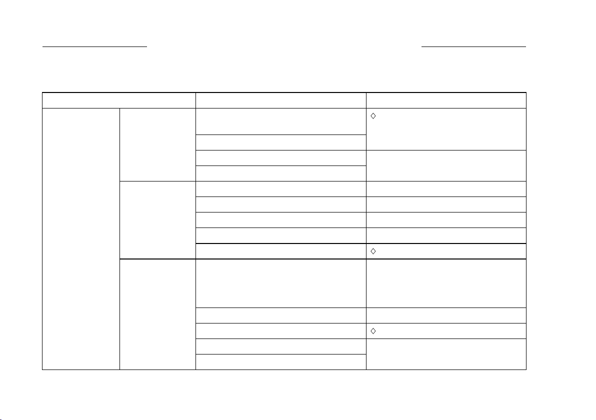
32 TROUBLESHOOTING GUIDE
TROUBLESHOOTING GUIDE
If the engine malfunctions, carefully examine the symptoms and the operating conditions, and use the table
below as a guide to troubleshooting.
Symptom Probably Cause
Remedy
Faulty pistons, cylinders, piston rings,
and head gaskets
Faulty valves
K
Loose spark plugs
Insufficient
compression
Loose cylinder head bolts
Tighten properly
No fuel in fuel tank Fill fuel tank
Fuel valve not in “ON” position Open fuel valve lever.
Blocked fuel filter or tube Change fuel filter or fuel tube
Blocked air vent in tank cap
Clean fuel tank cap
No fuel to
combustion
chamber
Faulty carburetor K
Over rich fuel/air mixture Open choke.
Rotate engine with spark plugs
removed to discharge excess fuel.
Clean spark plugs.
Clogged air cleaner Clean
Faulty carburetor K
Incorrect grade/type of fuel
Engine won’t
start or output is
low
Spark plugs
fouled by fuel
Water in fuel
Change fuel
34
TROUBLESHOOTING GUIDE
32 TROUBLESHOOTING GUIDE
TROUBLESHOOTING GUIDE
If the engine malfunctions, carefully examine the symptoms and the operating conditions, and use the table
below as a guide to troubleshooting.
Symptom Probably Cause
Remedy
Faulty pistons, cylinders, piston rings,
and head gaskets
Faulty valves
K
Loose spark plugs
Insufficient
compression
Loose cylinder head bolts
Tighten properly
No fuel in fuel tank Fill fuel tank
Fuel valve not in “ON” position Open fuel valve lever.
Blocked fuel filter or tube Change fuel filter or fuel tube
Blocked air vent in tank cap
Clean fuel tank cap
No fuel to
combustion
chamber
Faulty carburetor K
Over rich fuel/air mixture Open choke.
Rotate engine with spark plugs
removed to discharge excess fuel.
Clean spark plugs.
Clogged air cleaner Clean
Faulty carburetor K
Incorrect grade/type of fuel
Engine won’t
start or output is
low
Spark plugs
fouled by fuel
Water in fuel
Change fuel
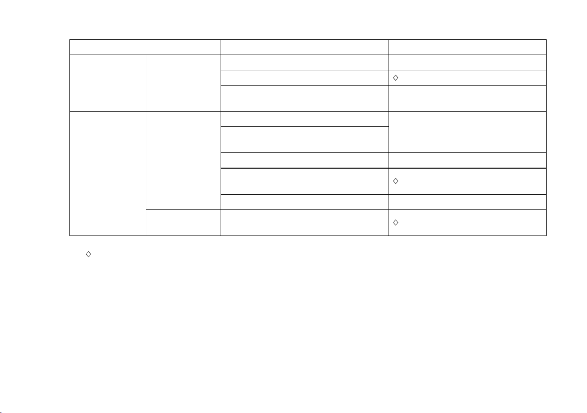
TROUBLESHOOTING GUIDE 33
Symptom Probably Cause Remedy
Faulty spark plugs Replace spark plugs
Faulty ignition coil K
No spark or
weak spark
Engine switch left in “OFF” position Turn engine switch to “START”
position (See M)
Clogged air cleaner
Air inlet screen or cooling air path
clogged with dirt
Clean
Insufficient engine oil
Replenish or c h ange oil
Carbon build-up in combustion
chamber
K
Engine
overheats
Poor ventilation around engine Select a better location
Low output
Engine speed
won’t increase
Faulty governor K
K: Service to be performed by an authorized Kawasaki dealer.
M: For Control Panel Switch Type, move the throttle lever on the equipment away from its low speed end
to turn the engine switch to “START” position.
Service to be performed by an authorized Kawasaki engine dealer or equally qualied service facility.
35
TROUBLESHOOTING GUIDE

34 ENVIRONMENTAL PROTECTION
ENVIRONMENTAL PROTECTION
To protect our environment, properly discard used batteries, engine oil, gasoline, coolant, or other compo-
nents that you might dispose of in the future.
Consult your authorized Kawasaki engine de aler or local environmental waste agency for their proper dis-
posal procedure.
Consult your authorized Kawasaki engine dealer or equally qualied service facility or local environmental
waste agency for their proper disposal procedure.
36
ENVIRONMENTAL PROTECTION
34 ENVIRONMENTAL PROTECTION
ENVIRONMENTAL PROTECTION
To protect our environment, properly discard used batteries, engine oil, gasoline, coolant, or other compo-
nents that you might dispose of in the future.
Consult your authorized Kawasaki engine de aler or local environmental waste agency for their proper dis-
posal procedure.
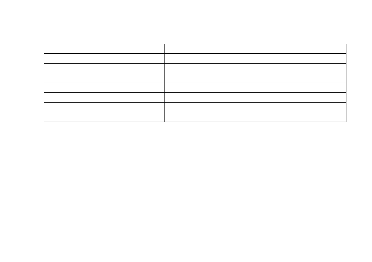
SPECIFICATIONS 35
SPECIFICATIONS
FR651V, FR691V, FR730V
Type
Air-cooled, 4-stroke OHV, V-twin cylinder, gasoline engine
Bore × Stroke 78 × 76 mm (3.07 × 2.99 in.)
Displacement
726 mL (44.3 cu.in)
Ignition System Solid-state ignition
Direction of Rotation Counterclockwise facing the PTO Shaft
Starting System
Electric starter
Dry Weight : kg (lbs) 40 (88.2)
NOTE
○
Specifications are subject to change without no-
tice.
○
Dry weight excludes that of fuel tank and muffler.
37
SPECIFICATIONS
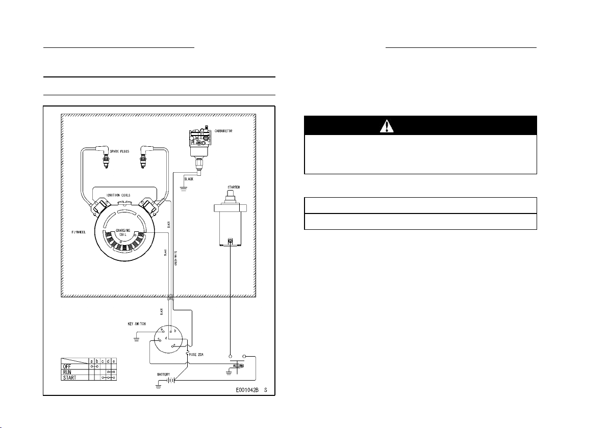
36 WIRING DIAGRAM
WIRING DIAGRAM
Wiring Diagram
NOTE
○
Portion Surrounded by hatching Shows Kawasaki
Procurement Parts.
WARNING
For electrical safety, always remove cable
from negative (–) side of battery before at-
tempting any repair or maintenance.
Battery Capacity Recommended
Battery Capacity
12 V 550 CCA Class
38
WIRING DIAGRAM
OWNER’S MANUAL
MANUAL DEL PROPIETARIO
Part No. 99920-2289-01
ESGB
Printed in Japan
FR651V
FR691V
FR730V
4-Stroke Air-Cooled V-Twin Gasoline Engine
Motor gasolina de 4 tiempos, V-gemelo y refrigerado por aire
The engine exhaust from this product
contains chemicals known to the
State of California to cause cancer,
birth defects or other reproductive
harm.
WARNING
Para realizar reparaciones u obtener asistencia
con la garantía, póngase en contacto con su
distribuidor autorizado de motores Kawasaki
local o instalación de mantenimiento con similar
cualificación,
correo electrónico:
teléfono gratuito 1-877-364-6404
El escape del motor de este producto
contiene productos químicos que,
según el Estado de California,
provocan cáncer, defectos de
nacimiento o afectan a la fecundidad.
ADVERTENCIA
For repair / warranty assistance please contact
your local authorized Kawasaki engine dealer
or equally qualified service facility,
email: [email protected] or
call toll-free 1-877-364-6404