
10’’ SLIDING COMPOUND MITER SAW
240-3689
For questions / comments, technical assistance or repair parts –
Please Call Toll Free: 1-866-858-2664. (M-F 8:30am-5:00pm Est.)
OPERATOR’S MANUAL
CAUTION:
To Reduce The Risk Of Injury, User Must Read And
Understand Operator’s Manual. Save These Instructions For Future
Reference.

TABLE OF CONTENTS
Safety Symbols ......................................................... Page 2
Safety Instructions ...................................................... Page 3
Overview/Specifications ................................................ Page 12
Assembly ............................................................ Page 14
Operation ............................................................ Page 15
Maintenance .......................................................... Page 26
Troubleshooting ....................................................... Page 29
Warranty ............................................................. Page 30
Page 2
SAFETY SYMBOLS
Some of these following symbols may be used on this tool. Please study them and learn their
meaning. Proper interpretation of these symbols will allow you to operate the tool better and
more safely.
Symbol
Name
Designation / Explanation
V Volts Voltage
A Amperes Current
Hz Hertz Frequency (cycles per second)
W Watts Power
∿
Alternating current Type of current
n
o
No-load speed Rotational speed at no load
RPM Revolutions per minute Unit of the speed
Class II construction Double insulated construction
Read the instruction
manual
To reduce the risk of injury, user must read
instruction manual
Warning symbol Never place hands near the cutting area.
WARNING:
To ensure safety and reliability, all repairs should be performed by a
qualied service technician.

Page 3
SAFETY INSTRUCTIONS
The purpose of safety symbols is to attract your attention to possible dangers. The safety
symbols, and the explanations with them, deserve your careful attention and understanding.
The symbol warnings do not, by themselves, eliminate any danger. The instructions and
warnings they give are no substitutes for proper accident prevention measures.
WARNING:
Be sure to read and understand all safety instructions in this manual,
including all safety alert symbols such as “DANGER”, “WARNING” and “CAUTION” before
using this tool. Failure to following all instructions listed below may result in electric
shock, re, and/or serious personal injury.
SYMBOL MEANING
SAFETY ALERT SYMBOL: Indicates DANGER, WARNING, OR CAUTION.
May be used in conjunction with other symbols or pictographs.
DANGER:
Indicates an imminently hazardous situation, which, if not avoided,
will result in death or serious injury.
WARNING:
Indicates a potentially hazardous situation, which, if not avoided,
could result in death or serious injury.
CAUTION:
Indicates a potentially hazardous situation, which, if not avoided, could
result in minor or moderate injury.
NOTICE: (Without Safety Alert Symbol) Indicates a situation that may result in property
damage.
SAVE THESE INSTRUCTIONS!

Page 4
WARNING:
Safety symbols in
this Instruction Manual are used to flag
possible dangers. The safety symbols
and their explanations require your full
understanding. The safety warnings do not,
by themselves, eliminate any danger, nor
are they substitutes for proper accident
prevention measures.
WARNING:
This Safety Alert
Symbol indicates caution, warning, or
danger. Failure to obey a safety warning
can result in serious injury to yourself or
others. To reduce the risk of injury, fire,
or electric shock, always follow the safety
precautions.
KNOW YOUR TOOL
To operate this tool, carefully read this
Instruction Manual and all labels affixed
to the miter saw before using. Keep this
instruction manual available for future
reference.
READ ALL INSTRUCTIONS
THOROUGHLY.
SAVE THESE INSTRUCTIONS.
GENERAL POWER TOOL SAFETY
WARNINGS
WARNING:
Read all safety
warnings, instructions, illustrations and
specications provided with this power tool.
Failure to follow all instructions listed below
may result in electric shock, fire and/or serious
injury.
SAVE ALL WARNINGS AND
INSTRUCTIONS FOR FUTURE
REFERENCE.
The term “power tool” in the warnings refers
to your mains-operated (corded) power tool
or battery-operated (cordless) power tool.
WORK AREA SAFETY
• Keep work area clean and well lit.
Cluttered or dark areas invite accidents.
• Do not operate power tools in
explosive atmospheres, such as in the
presence of ammable liquids, gases
or dust. Power tools create sparks
which may ignite the dust or fumes.
• Keep children and bystanders
away while operating a power tool.
Distractions can cause you to lose
control.
ELECTRICAL SAFETY
• Power tool plugs must match the
outlet. Never modify the plug in any
way. Do not use any adapter plugs
with earthed (grounded) power tools.
Unmodified plugs and matching outlets
will reduce risk of electric shock.
• Avoid body contact with earthed or
grounded surfaces, such as pipes,
radiators, ranges and refrigerators.
There is an increased risk of electric
shock if your body is earthed or
grounded.
• Do not expose power tools to rain
or wet conditions. Water entering a
power tool will increase the risk of
electric shock.
• Do not abuse the cord. Never use the
cord for carrying, pulling or unplugging
the power tool. Keep cord away from
heat, oil, sharp edges or moving parts.
Damaged or entangled cords increase
the risk of electric shock.
SAFETY INSTRUCTIONS

Page 5
• When operating a power tool
outdoors, use an extension cord
suitable for outdoor use. Use of a cord
suitable for outdoor use reduces the
risk of electric shock.
• If operating a power tool in a damp
location is unavoidable, use a
ground fault circuit interrupter (GFCI)
protected supply. Use of an GFCI
reduces the risk of electric shock.
PERSONAL SAFETY
• Stay alert, watch what you are
doing and use common sense when
operating a power tool. Do not use
a power tool while you are tired or
under the inuence of drugs, alcohol
or medication. A moment of inattention
while operating power tools may result
in serious personal injury.
• Use personal protective equipment.
Always wear eye protection. Protective
equipment such as a dust mask, non-
skid safety shoes, hard hat or hearing
protection used for appropriate
conditions will reduce personal injuries.
• Prevent unintentional starting. Ensure
the switch is in the off-position before
connecting to power source and/or
battery pack, picking up or carrying
the tool. Carrying power tools with
your finger on the switch or energizing
power tools that have the switch on
invites accidents.
• Remove any adjusting key or wrench
before turning the power tool on.
A wrench or a key left attached to a
rotating part of the power tool may
result in personal injury.
• Do not overreach. Keep proper
footing and balance at all times. This
enables better control of the power tool
in unexpected situations.
• Dress properly. Do not wear loose
clothing or jewelery. Keep your hair
and clothing away from moving parts.
Loose clothes, jewelery or long hair can
be caught in moving parts.
• If devices are provided for the
connection of dust extraction and
collection facilities, ensure these are
connected and properly used. Use of
dust collection can reduce dust-related
hazards.
• Do not let familiarity gained from
frequent use of tools allow you to
become complacent and ignore tool
safety principles. A careless action can
cause severe injury within a fraction of
a second.
POWER TOOL USE AND CARE
• Do not force the power tool. Use
the correct power tool for your
application. The correct power tool will
do the job better and safer at the rate
for which it was designed.
• Do not use the power tool if the switch
does not turn it on and off. Any power
tool that cannot be controlled with
the switch is dangerous and must be
repaired.
• Disconnect the plug from the power
source and/or remove the battery
pack, if detachable, from the power
tool before making any adjustments,
changing accessories, or storing
power tools. Such preventive safety
measures reduce the risk of starting the
power tool accidentally.
• Store idle power tools out of the reach
of children and do not allow persons
unfamiliar with the power tool or
these instructions to operate the
power tool. Power tools are dangerous
in the hands of untrained users.
• Maintain power tools and accessories.
Check for misalignment or binding of
moving parts, breakage of parts and
any other condition that may affect the
power tool’s operation. If damaged,
have the power tool repaired before
use. Many accidents are caused by
poorly maintained power tools.
SAFETY INSTRUCTIONS

Page 6
• Keep cutting tools sharp and clean.
Properly maintained cutting tools with
sharp cutting edges are less likely to
bind and are easier to control.
• Use the power tool, accessories and
tool bits etc. in accordance with these
instructions, taking into account the
working conditions and the work to
be performed. Use of the power tool
for operations different from those
intended could result in a hazardous
situation.
• Keep handles and grasping surfaces
dry, clean and free from oil and
grease. Slippery handles and grasping
surfaces do not allow for safe handling
and control of the tool in unexpected
situations.
SERVICE
• Have your power tool serviced by
a qualied repair person using only
identical replacement parts. This will
ensure that the safety of the power tool
is maintained.
SAFETY INSTRUCTIONS FOR
MITER SAWS
• Miter saws are intended to cut wood
or wood-like products, they cannot be
used with abrasive cut-off wheels for
cutting ferrous material such as bars,
rods, studs, etc. Abrasive dust causes
moving parts such as the lower guard
to jam. Sparks from abrasive cutting
will burn the lower guard, the kerf insert
and other plastic parts.
• Use clamps to support the workpiece
whenever possible. If supporting the
workpiece by hand, you must always
keep your hand at least 100 mm from
either side of the saw blade. Do not
use this saw to cut pieces that are
too small to be securely clamped or
held by hand. If your hand is placed
too close to the saw blade, there is
an increased risk of injury from blade
contact.
• The workpiece must be stationary
and clamped or held against both
the fence and the table. Do not feed
the workpiece into the blade or cut
“freehand” in any way. Unrestrained or
moving workpieces could be thrown at
high speeds, causing injury.
• Push the saw through the workpiece.
Do not pull the saw through the
workpiece. To make a cut, raise the
saw head and pull it out over the
workpiece without cutting, start the
motor, press the saw head down and
push the saw through the workpiece.
Cutting on the pull stroke is likely to
cause the saw blade to climb on top of
the workpiece and violently throw the
blade assembly towards the operator.
• Never cross your hand over the
intended line of cutting either in front
or behind the saw blade. Supporting
the workpiece “cross handed” i.e.
holding the workpiece to the right of
the saw blade with your left hand or
vice versa is very dangerous.
• Do not reach behind the fence with
either hand closer than 100 mm
from either side of the saw blade, to
remove wood scraps, or for any other
reason while the blade is spinning. The
proximity of the spinning saw blade to
your hand may not be obvious and you
may be seriously injured.
• Inspect your workpiece before
cutting. If the workpiece is bowed
or warped, clamp it with the outside
bowed face toward the fence. Always
make certain that there is no gap
between the workpiece, fence and
table along the line of the cut. Bent or
warped workpieces can twist or shift
and may cause binding on the spinning
saw blade while cutting. There should
be no nails or foreign objects in the
workpiece.
SAFETY INSTRUCTIONS

Page 7
• Do not use the saw until the table
is clear of all tools, wood scraps,
etc., except for the workpiece. Small
debris or loose pieces of wood or other
objects that contact the revolving blade
can be thrown with high speed.
• Cut only one workpiece at a time.
Stacked multiple workpieces cannot
be adequately clamped or braced and
may bind on the blade or shift during
cutting.
• Ensure the miter saw is mounted or
placed on a level, rm work surface
before use. A level and firm work
surface reduces the risk of the miter
saw becoming unstable.
• Plan your work. Every time you change
the bevel or miter angle setting,
make sure the adjustable fence is set
correctly to support the workpiece
and will not interfere with the blade or
the guarding system. Without turning
the tool “ON” and with no workpiece on
the table, move the saw blade through
a complete simulated cut to assure
there will be no interference or danger
of cutting the fence.
• Provide adequate support such as
table extensions, saw horses, etc. for
a workpiece that is wider or longer
than the table top. Workpieces longer
or wider than the miter saw table can
tip if not securely supported. If the cut-
off piece or workpiece tips, it can lift
the lower guard or be thrown by the
spinning blade.
• Do not use another person as a
substitute for a table extension or as
additional support. Unstable support
for the workpiece can cause the blade
to bind or the workpiece to shift during
the cutting operation pulling you and
the helper into the spinning blade.
• The cut-off piece must not be jammed
or pressed by any means against the
spinning saw blade. If confined, i.e.
using length stops, the cut-off piece
could get wedged against the blade
and thrown violently.
SAFETY INSTRUCTIONS
• Always use a clamp or a xture
designed to properly support round
material such as rods or tubing. Rods
have a tendency to roll while being cut,
causing the blade to “bite” and pull the
work with your hand into the blade.
• Let the blade reach full speed before
contacting the workpiece. This will
reduce the risk of the workpiece being
thrown.
• If the workpiece or blade becomes
jammed, turn the miter saw off.
Wait for all moving parts to stop and
disconnect the plug from the power
source and/or remove the battery
pack. Then work to free the jammed
material. Continued sawing with a
jammed workpiece could cause loss of
control or damage to the miter saw.
• After nishing the cut, release the
switch, hold the saw head down
and wait for the blade to stop before
removing the cut-off piece. Reaching
with your hand near the coasting blade
is dangerous.
• Hold the handle rmly when making
an incomplete cut or when releasing
the switch before the saw head is
completely in the down position. The
braking action of the saw may cause
the saw head to be suddenly pulled
downward, causing a risk of injury.
ADDITIONAL SAFETY RULES
FOR MITER SAW
• Do not operate this machine until it is
completely assembled and installed
according to the instructions. A
machine incorrectly assembled can
cause serious injury.
• Obtain advice from your supervisor,
instructor, or another qualied person
if you are not thoroughly familiar
with the operation of this machine.
Knowledge is safety.
• Make certain the blade rotates in the

Page 8
correct direction. The teeth on the
blade should point in the direction of
rotation as marked on the saw.
• Tighten all clamp handles, knobs and
levers prior to operation. Loose clamps
can cause parts or the workpiece to be
thrown at high speeds.
• Be sure all blade and blade clamps are
clean, recessed sides of blade clamps
are against blade and arbor screw is
tightened securely. Loose or improper
blade clamping may result in damage
to the saw and possible personal injury.
• Do not wedge anything against the
fan to hold the motor shaft. Damage
to tool and possible personal injury
may occur.
• Never cut ferrous metals (those with
any iron or steel content) or masonry.
Either of these can cause the carbide
tips to fly off the blade at high speeds
causing serious injury.
• Do not use abrasive wheels or blades.
The excessive heat and abrasive
particles generated by them may
damage the saw and cause personal
injury.
• Never have any part of your body in
line with the path of the saw blade.
Personal injury will occur.
• Never apply blade lubrication to a
running blade. Applying lubricant
could cause your hand to move into the
blade resulting in serious injury.
• Do not place either hand in the blade
area when the saw is connected to
the power source. Inadvertent blade
activation may result in serious injury.
• Never reach around or behind the saw
blade. A blade can cause serious injury.
• Do not reach underneath the saw
unless it is unplugged and turned off.
Contact with saw blade may cause
personal injury.
• Secure the machine to a stable
supporting surface. Vibration can
possibly cause the machine to slide,
walk, or tip over, causing serious injury.
SAFETY INSTRUCTIONS
• Use only blades of the correct size
and type specied for this tool to
prevent damage to the machine and/
or serious injury.
• Inspect blade for cracks or other
damage prior to operation. A cracked
or damaged blade can come apart and
pieces can be thrown at high speeds,
causing serious injury. Replace cracked
or damaged blades immediately.
• Clean the blade and blade clamps
prior to operation. Cleaning the blade
and blade clamps allows you to check
for any damage to the blade or blade
clamps. A cracked or damaged blade
or blade clamp can come apart and
pieces can be thrown at high speeds,
causing serious injury.
• Do not use warped blades. Check to
see if the blade runs true and is free
from vibration. A vibrating blade can
cause damage to the machine and/or
serious injury.
• Keep guard in place and in working
order.
• Always use the kerf plate and replace
this plate when damaged. Small chip
accumulation under the saw may
interfere with the saw blade or may
cause instability of workpiece when
cutting.
• Use only blade clamps specied for
this tool to prevent damage to the
machine and/or serious injury.
• Clean the motor air slots of chips
and sawdust. Clogged motor air slots
can cause the machine to overheat,
damaging the machine and possibly
causing a short which could cause
serious injury.
• Never lock the switch in the “ON”
position. Severe personal injury may
result.
• Never stand on tool. Serious injury
could occur if the tool is tipped or
if the cutting tool is unintentionally
contacted.

Page 9
SAFETY INSTRUCTIONS
• Never leave tool running unattended.
Turn power off. Don’t leave tool until it
comes to a complete stop.
• To reduce the risk of injury, return the
saw head to the full rear position after
each crosscut operation.
• Always make sure that the miter
table and head assembly (bevel
function) are locked in position
BEFORE operating your saw. Lock the
miter table by securely tightening the
miter locking handle. Lock the head
assembly (bevel function) by securely
tightening the bevel locking knob.
• Support long workpieces when
cutting to minimize the risk of blade
pinching or kickback. The saw may
slip, walk or slide while cutting long or
heavy boards.
• Avoid awkward operations and hand
positions where a sudden slip could
cause your hand to hit the blade.
Always make sure you have good
balance. Never operate your saw on
the floor or in a crouched position.
• Never use solvents to clean plastic
parts. Solvents could dissolve or
otherwise damage the material.
• Do not turn the motor switch on and
off rapidly. This could cause the blade
to loosen, which could create a hazard.
Should this ever occur, stand clear
and allow the saw blade to come to
a complete stop. Disconnect the saw
from the power source and tighten the
blade bolt securely.
• Never lift this tool by gripping the
switch handle or by the miter fence.
This may cause misalignment. Always
lock the head assembly in the “DOWN”
position and carry the saw by holding
the base or lift it using the carrying
handle/support bracket.
• Always check the tool for damaged
parts. Before further use of the tool,
a guard or other part that is damaged
should be carefully checked to
determine whether it will operate
properly and perform its intended
function. Check for misalignment or
binding of moving parts, broken parts
and any other condition that may
affect the tool’s operation. A guard
or other part that is damaged should
be properly repaired or replaced by a
qualified person.
• Use proper extension cord. Make
sure your extension cord is in good
condition. When using an extension
cord, be sure to use one heavy enough
to carry the current your product will
draw. An undersized cord will cause
a drop in line voltage resulting in
loss of power and overheating. The
following table shows the correct size
to use depending on cord length and
nameplate ampere rating. If in doubt,
use the next heavier gauge. The
smaller the gauge number, the heavier
the cord.
Recommended sizes of extension cords:
Tool’s
ampere
rating
Volts
Total length of cord in feet
Cord size in AWG. (minimum)
25’ 50’ 100’ 150’
0-6
120 V~
18 16 16 14
6-10 18 16 14 12
10-12 16 16 14 12
12-16 14 12 Not recommended
Page 10
SAFETY INSTRUCTIONS
• If the supply cord of this power tool
is damaged, it must be replaced
by a specially prepared supply
cord available through the service
organization.
• Save these instructions. Refer to
them frequently and use them to
instruct others who may use this tool. If
someone borrows this tool, make sure
he or she has these instructions also.
DOUBLE-INSULATED TOOLS
• To reduce the risk of electric shock,
double-insulated tools are equipped
with a polarized plug (one blade is
wider than the other). This plug will
fit into a polarized outlet only one way.
If the plug does not fit into the outlet
properly, reverse the plug. If it still does
not fit, contact a qualified electrician to
install a polarized outlet. Do not change
the plug in any way.
• Double insulation eliminates the need
for the three-wire grounded power
cord and grounded power supply
system. This compound miter saw is a
double-insulated tool.
Cover of Grounded
Outlet Box
GLOSSARY OF WOODWORKING
TERMS
1. Spindle: The revolving shaft on which a
blade or cutting tool is mounted.
2. Spindle Lock: Allows the user to stop
the blade from rotating while tightening
or loosening the blade screw during
blade replacement or removal.
3. Bevel Cut: A cutting operation made
with the blade at any angle other than
90° to the miter table.
4. Chamfer Cut: A cut that removes a
wedge from a block of wood so that
the end (or part of the end) is angled at
other than 90°.
5. Compound Miter Cut: A cut made using
both a miter angle and a bevel angle at
the same time.
6. Crosscut: A cutting operation made
across the grain of the workpiece.
7. Slide Rails: Guide the head assembly
when making a slide cut.
8. Head Assembly Locking pin: The
compound miter saw is equipped with a
locking pin that is used to lock the head
assembly in the down position.
9. Flange: A ring or collar on the end of
a spindle or arbor that permits other
objects, such as a blade, to be attached
to it.
10. Freehand Cut: Performing a cut without
using a fence, miter gauge, fixture, work
clamp, or other proper device to keep
the workpiece from twisting or moving
during the cut. Do not perform any
operation freehand. Use a clamp or vise
wherever possible.
11. Kerf: The material removed by the blade
in a through cut, or the slot produced by
the blade in a non-through or partial cut.
12. Kickback: A hazard that can occur when
the blade binds or stalls, throwing the
workpiece back toward the operator.
13. Miter Cut: A cutting operation made with
the blade at any angle other than 90° to
the fence.

Page 11
SAFETY INSTRUCTIONS
14. No-Hands Zone: The area between the
marked lines on the left and right side
of the miter-table base. This zone is
identified by No-Hands Zone symbols
inside the lines marked on the miter
table base.
15. Non-through Cut: Any cutting operation
where the blade does not extend
completely through the thickness of the
workpiece.
16. Revolutions Per Minute (RPM): The
number of turns completed by a
spinning object in one minute.
17. Saw Blade Path: The area over, under,
behind, or in front of the blade, as it
applies to the workpiece; the area that
will be or has been cut by the blade.
18. Set: The distance that the saw blade
tooth is bent (or set) outward from the
face of the blade.
19. Throat Plate: A plate inserted in the
Miter Saw’s table that allows for blade
clearance.
20. Through Sawing: Any cutting operation
where the blade extends completely
through the thickness of the workpiece.
21. Workpiece or Material: The item on
which the cutting operation is being
done. The surfaces of a workpiece are
commonly referred to as faces, ends,
and edges.
DANGER:
People with electronic
devices, such as pacemakers, should
consult their physician(s) before using this
product. Operation of electrical equipment
in close proximity to a heart pacemaker
could cause interference or failure of the
pacemaker.
WARNING:
• Some dust created by power sanding,
sawing, grinding, drilling, and other
construction activities contains
chemicals known to the state of
California to cause cancer, birth
defects, or other reproductive harm.
Some examples of these chemicals
are:
− Lead from lead-based paints
− Crystalline silica from bricks, cement,
and other masonry products
− Arsenic and chromium from chemically-
treated lumber
• Your risk from these exposures varies,
depending upon how often you do this
type of work. To reduce your exposure
to these chemicals:
− Work in a well-ventilated area.
− Work with approved safety equipment,
such as dust masks that are specially
designed to filter out microscopic
particles.
− Avoid prolonged contact with dust
from power sanding, sawing, grinding,
drilling, and other construction
activities. Wear protective clothing
and wash exposed areas with soap
and water. Allowing dust to get into
your mouth or eyes or to lie on the skin
may promote absorption of harmful
chemicals.
SAVE THESE INSTRUCTIONS!
Page 12
OVERVIEW
Switch
Lower Blade
Guard
Mounting
Hole
Table Insert
Miter Locking Knob
Depth Adjustment Screw
Lock-down Pin
Slide-Rail Lock Knob
Bevel Scale
Bevel Lock Knob
Miter Stop
Locking Lever
Miter Scale
Base
Table
Spindle Lock
Extension Bar
Lower Fence
Sliding Fence
Work Clamp
Dust Bag

Page 13
SPECIFICATIONS
Motor 120V~, 60Hz, 15A
Speed 5000 RPM (no load)
Blade 10" (25.4 cm) (40-tooth)
Arbor size 5/8" (15.9 mm)
Cutting capacity
3-1/2’’X12-3/8’’, miter 0°, bevel 0°
3-1/2’’X8-7/16’’, miter 45°, bevel 0°
1-9/16’’X12-3/8’’, miter 0°, bevel 45°
1-9/16’’X8-7/16’’, miter 45°, bevel 45°
Weight 36 lb. 5 oz.

Page 14
WARNING:
If any part is broken or
missing, DO NOT operate the tool until the
broken or missing part is replaced. Failure
to do so could result in possible serious
injury.
WARNING:
Do not attempt to
modify this tool or create accessories not
recommended for use with this tool. Any
such alteration or modication is misuse
and could result in a hazardous condition
leading to possible serious injury.
WARNING:
Your tool should
never be connected to the power source
when you are assembling parts, making
adjustments, cleaning, or when it is not in
use. Disconnecting the tool will prevent
accidental starting, which could cause
serious personal injury.
ASSEMBLY
CONTENTS
Sliding compound miter saw, miter lever,
work clamp, dust bag, 2 extension bars,
phillips screwdriver and instruction manual.
UNPACKING
1. Carefully remove the tool and any
accessories from the carton. Make sure
that all items listed in the packing list are
included.
2. Inspect the tool carefully to make sure
that no breakage or damage occurred
during shipping.
3. Do not discard the packing material
until you have carefully inspected and
satisfactorily operated the tool.
Page 15
INTENDED USE
This miter saw is designed for wood cutting
applications. DO NOT use under wet
conditions or in presence of flammable
liquids or gases. DO NOT let children come
into contact with the tool. Supervision is
required when inexperienced operators use
this tool.
BENCH MOUNTING (FIG.1)
FIG. 1
Mounting
Hole
This tool should be bolted with four bolts to a
level and stable surface using the mounting
holes provided in the tool’s base. This will
help prevent tipping and possible injury.
WARNING:
Ensure that the
tool will not move on the supporting
surface. Movement of the miter saw on
the supporting surface while cutting
may result in loss of control and serious
personal injury.
INSTALL THE WORK CLAMP
(FIG.2)
There are two mounting holes for the work
clamp. These are located just behind the
fence on the left and right side of the base.
1. Loosen the screw (1) counterclockwise.
2. Place the work clamp in the desired
mounting hole.
3. Tighten the screw (1) to lock the work
clamp.
4. Rotate the clamp knob clockwise to
clamp the workpiece and rotate the
knob counterclockwise to release the
pressure. Lock the screw (2) before
working.
FIG. 2
Screw(2)Screw(1)
Clamp
Knob
Work
Clamp
INSTALL/REMOVE THE SLIDING
FENCE (FIG.3)
FIG. 3
Lower
Fence
Locking
Screw
Slot
Sliding
Fence
1. Loosen the locking screw to clear the
slot on the lower fence.
2. Insert the sliding fence into the slot and
slide it to the desired position.
3. Tighten the locking screw securely.
4. To remove the sliding fence, just loosen
the locking screw and then slide the
fence out.
OPERATION
Page 16
INSTALL EXTENSION BARS
(FIG.4)
Extension bars have been provided for both
the left and the right side of the saw.
1. Remove the screw from the end of the
extension bar.
2. Insert the ends of extension bar into the
holes in the sides of the base.
3. Replace screw and tighten to secure the
extension bar in place.
4. Repeat for the other extension bar.
5. If you want to adjust the extension bar,
you can loosen the locking screw, push
or pull the extension bar to the desired
position, and then tighten the locking
screw.
FIG. 4a
Base
Extension
Bar
Locking
Screw
FIG. 4b
Screws
NOTICE: Remove the locking screws on
the base before installing the extension
bars.
WARNING:
Always use extension
bars to support a long workpiece so it
is level with the top surface of the main
table for an accurate cut and to prevent
dangerous loss of control.
INSTALL THE DUST BAG (FIG.5)
Align the dust bag with the dust port on
the miter saw and then insert the dust bag
onto the dust port. Close the zipper before
operating the miter saw. The dust port also
accepts a standard 1-1/4” (3.2 cm) vacuum
tube for dust collection.
NOTICE: Check bag frequently and empty
it before it gets full. To empty the dust
bag, remove it from the dust port. Open
the zipper on underside of bag and empty
the dust into waste container.
FIG. 5
Zipper
Dust Bag
Dust
Port
OPERATION
Page 17
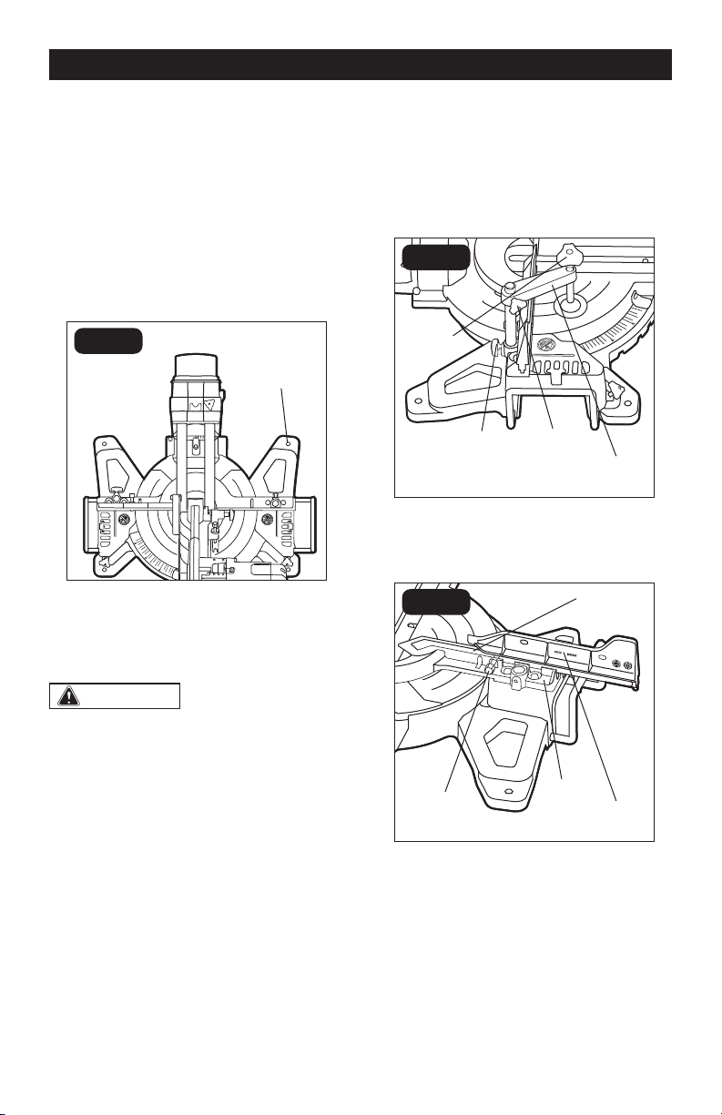
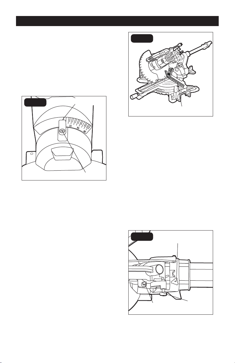
MITER SCALE (FIG.6)
FIG. 6a
Miter Lever
Hole
FIG. 6b
Miter-angle
Indicator
Screw
Detent Slot
Miter Stop
Locking
Lever
Miter
Locking
Knob
To install the miter lever:
The miter lever is put aside from the miter
saw during transport. Before operation,
align the miter lever with the hole on the
front of the miter saw, and then rotate the
miter lever clockwise to screw the lever onto
the miter saw.
To adjust miter angles:
The sliding compound miter saw scale can
be easily read, showing miter angles from 0°
to 45° to the left, and 0° to 45° to the right.
The miter saw table has nine common angle
settings with positive stops at 0°, 15°, 22.5°,
31.6° and 45°. These positive stops position
the blade at the desired angle quickly and
accurately.
1. Unlock the table by turning the miter
OPERATION
locking knob counterclockwise.
2. Move the table while lifting up on the
miter stop locking lever to align the
indicator to the desired degree.
3. If the desired angle is one of the nine
positive stops, release the miter stop
locking lever, make sure the lever snaps
into the detent slot, and then secure
by tightening the miter locking knob
clockwise.
4. If the desired angle is not one of the nine
positive stops, simply lock the table
into desired angle position by turning
the miter locking knob in the clockwise
direction.
Miter-angle indicator adjustment
This tool is carefully adjusted and aligned
at the factory, but rough handling may have
affected the alignment. If your tool is not
aligned properly, perform the following as
needed.
1. Move the table to the 0° positive stop.
2. Loosen the screw that holds the
indicator with a cross-head screwdriver.
3. Adjust the indicator to the 0° mark and
retighten the screw.
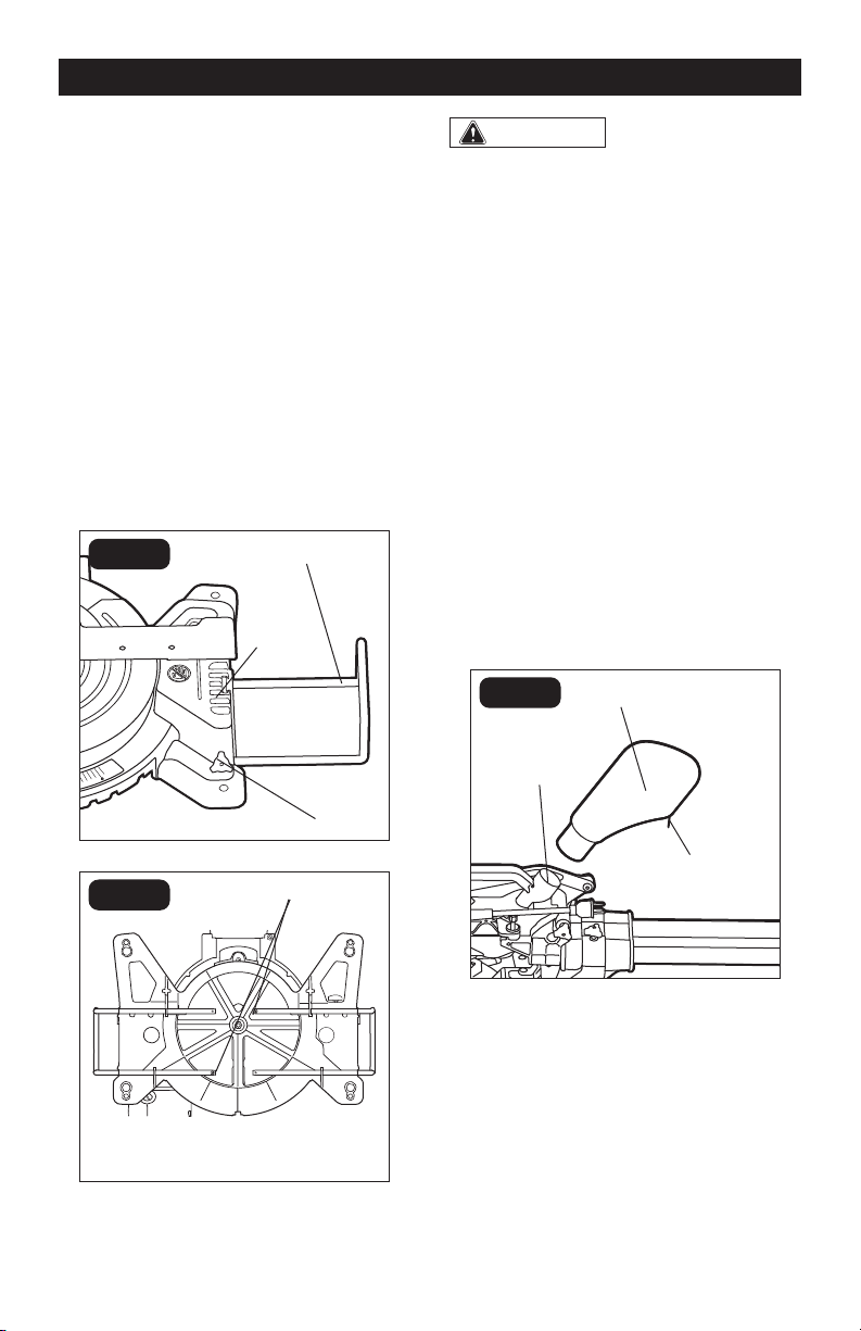
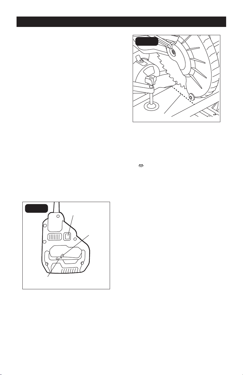
ADJUST THE FENCE
SQUARENESS (FIG.7)
FIG. 7a
Carpenter’s
Square
Page 18
FIG. 7b
Lower
Fence
Hex-head
Bolts
1. Unplug the saw.
2. Set the bevel and miter angles to 0°.
3. Lower and lock the saw arm in the
“DOWN” position.
4. Place the heel of a carpenter’s square
(available separately) against the blade
and the ruler of the square against the
fence (Fig.7a).
5. If the blade is not 90° to the fence,
completely unscrew the locking screw of
the sliding fence and remove the sliding
fence (refer to “INSTALL/REMOVE THE
SLIDING FENCE” section).
6. Loosen the four hex-head bolts (Fig.7b)
on both sides of the lower fence with a
5 mm hex wrench and rotate the lower
fence until the blade is square to the
lower fence. Retighten the hex-head
bolts. Remount the sliding fence.
NOTICE:
• Be sure to rest the square against the
body of the blade, and not against the
teeth of the blade.
• If the saw has not been used recently,
verify that the blade is square to the
fence, and readjust if necessary.
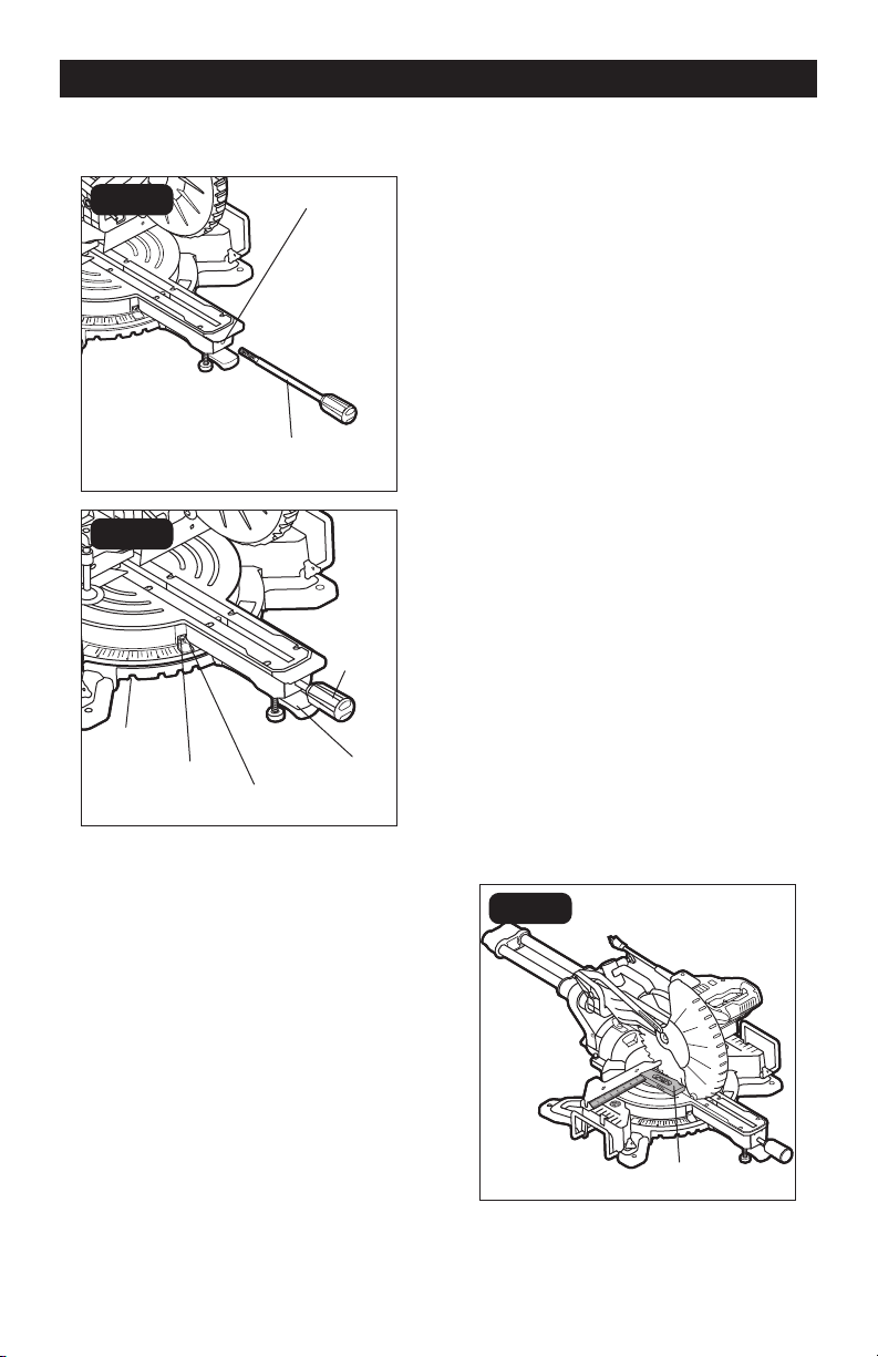
BEVEL STOP ADJUSTMENT
(FIG.8)
This tool is carefully adjusted and aligned
at the factory, but rough handling may have
affected the alignment. If your tool is not
aligned properly, perform the following as
needed.
90° (0°) bevel adjustment
FIG. 8a
Carpenter’s
Square
FIG. 8b
Nut
Bevel Lock
Knob
Hole
Bolt
1. Loosen bevel lock knob. Tilt the cutting
arm completely to the right. Tighten the
bevel lock knob.
2. Place a combination square on the
table with the ruler against the table and
the heel of the square against the saw
blade.
OPERATION
Page 19
3. If the blade is not 90° square with the
table, loosen the bevel lock knob,
put a 4 mm hex wrench into the hole
located in the left side end of the arm
holder, turn the hex screw clockwise
or counterclockwise to make the blade
square to the table.
4. Tighten bevel lock knob when alignment
is achieved.
90° bevel pointer adjustment
FIG. 8c
Screw
Bevel
Indicator
When the blade is exactly 90° to the table,
loosen the bevel indicator screw using
a cross-head screwdriver. Adjust bevel
indicator to the “0” mark on the bevel scale
and retighten the screw.
45° bevel adjustment
1. Loosen the bevel lock knob (FIG.8b) and
tilt the cutting head completely to the
left.
2. Using a combination square, check to
see whether the blade angle is 45° to the
table.
3. If the blade is not at 45° to the miter table,
tilt the pivot arm to the right, loosen the
nut (FIG.8b) on the bolt (FIG.8b) and use
a 5 mm hex wrench to adjust the bolt
depth in or out to increase or decrease
the bevel angle.
4. Tilt the cutting arm to the left to 45°
bevel and recheck for alignment.
5. Repeat steps until the blade is at 45° to
the miter table.
6. Tighten the bevel lock knob and nut
(FIG.8b) when alignment is achieved.
FIG. 8d
Combination
Square
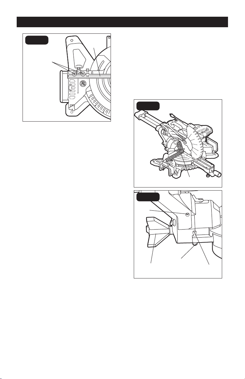
GUARD ACTUATION AND
CHECKING
The blade guard on your saw has been
designed to automatically raise when the arm
is brought down and to lower over the blade
when the arm is raised.
The guard can be raised by hand when
installing or removing saw blades or for
inspection of the saw. NEVER RAISE THE
BLADE GUARD MANUALLY UNLESS THE
SAW IS TURNED OFF.
UNLOCK AND LOCK THE
CUTTING HEAD (FIG.9)
FIG. 9
Lock-down
Pin
Slide-rail Lock
Knob
Depth Adjustment
Screw
To unlock: Press and lightly hold down the
cutting head. Pull out the lock-down pin to
release the cutting head. The cutting head
should freely move up.
OPERATION
Page 20
OPERATION
To lock: Place the cutting head at the
lowest position. Secure the position and
push the lock-down pin into the locking
position. Please note, if there is any cutting
depth setting, the lock-down pin may not
work. Release the cutting depth limitation
by rotating the depth adjustment screw
counterclockwise, and then lock the cutting
head.
UNLOCK THE SLIDE RAIL (FIG.9)
The slide-rail lock knob is located on
the upper side of the slide rail. Loosen
the slide rail by rotating the lock knob
counterclockwise, and then you can move
the slide rail freely. If you want to lock the
slide rail, just rotate the lock knob clockwise.
When transporting or storing the miter saw,
the slide rail should always be locked in
position.
LED WORKLIGHT (FIG.10)
FIG. 10a
Lock-off
Lever
Led Worklight
Switch
On/off Trigger
Switch
FIG. 10b
Blade
Shadow
Your miter saw has a LED worklight, located
in the upper guard for the saw blade.
1. Mark your workpiece with a pencil line
at the point to be cut.
2. Press the LED worklight switch to the
“ ” position to turn on the light. Align
your pencil line with the straight light
line.
3. Fully clamp your workpiece in place.
Follow all of the cutting instructions for
the type of cut to be performed.
4. Press the LED worklight switch to the
“OFF” position to turn off the light.
TRIGGER SWITCH (FIG.10a)
To turn the saw on, push the lock-off lever
to the left, then depress the on/off trigger
switch. To turn the tool off, release the trigger
switch. When the trigger switch is released,
the blade will be stopped within 10 seconds.
Page 21
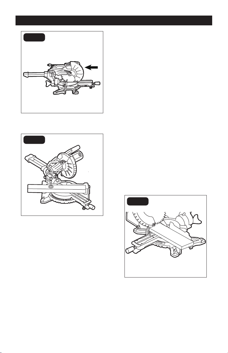
CHOP CUTS (FIG.11)
FIG. 11
Chop cuts are used mainly for narrow
pieces.
1. Unplug the saw.
2. Slide the head assembly to the rear as
far as it will go.
3. Tighten the slide-rail locking knob.
4. Plug the saw into an electrical socket.
5. Properly position the workpiece. Make
sure the workpiece is clamped firmly
against the table and the fence. Use a
clamping position that does not interfere
with the cutting operation.
6. Before turning the saw on, lower the
head assembly to make sure the clamp
clears the guard and head assembly.
7. Turn on the switch. Lower the head
assembly and make your cut.
8. Wait until blade comes to a complete
stop before returning the head assembly
to the raised position and or removing
workpiece.
SLIDE CUTS (FIG.12)
This type of cut is used mainly for wide
pieces.
1. Properly position workpiece. Make sure
workpiece is clamped firmly against
the table and the fence. Use clamping
position that does not interfere with
operation. Before switching tool on,
lower head assembly to make sure
clamp clears guard and head assembly.
2. Loosen the slide-rail lock knob.
3. Grasp the switch handle and pull the
head assembly away from the fence,
until the blade clears the workpiece
or to its maximum extension if blade
cannot clear the workpiece.
4. Turn on the switch. Always allow the
blade to reach full speed before cutting.
5. Lower the head assembly all the way
down, and cut through the edge of the
workpiece.
6. Push (but do not force) the head
assembly toward the fence all the way
to the rear position to complete the cut.
7. Wait until the blade comes to a complete
stop before returning the head assembly
to the raised position and/or removing
the workpiece.
WARNING:
NEVER pull the saw
toward you during a cut. The blade can
suddenly climb the workpiece causing
KICKBACK.
FIG. 12a
OPERATION
Page 22
OPERATION
FIG. 12b
MITER CUT (FIG.13)
FIG. 13
1. Loosen miter locking knob. While
holding the miter locking knob, lift miter
stop locking lever and move the saw to
the desired angle. Tighten miter locking
knob. Refer to “MITER SCALE” section
for instructions.
2. Properly position workpiece. Make sure
workpiece is clamped firmly against the
table. Use clamping position that does
not interfere with operation. Before
switching on, lower head assembly to
make sure clamp clears guard and head
assembly.
3. Follow procedures for either chop cuts
or slide cuts.
4. Wait until blade comes to a complete
stop before returning head assembly
to the raised position and/or removing
workpiece.
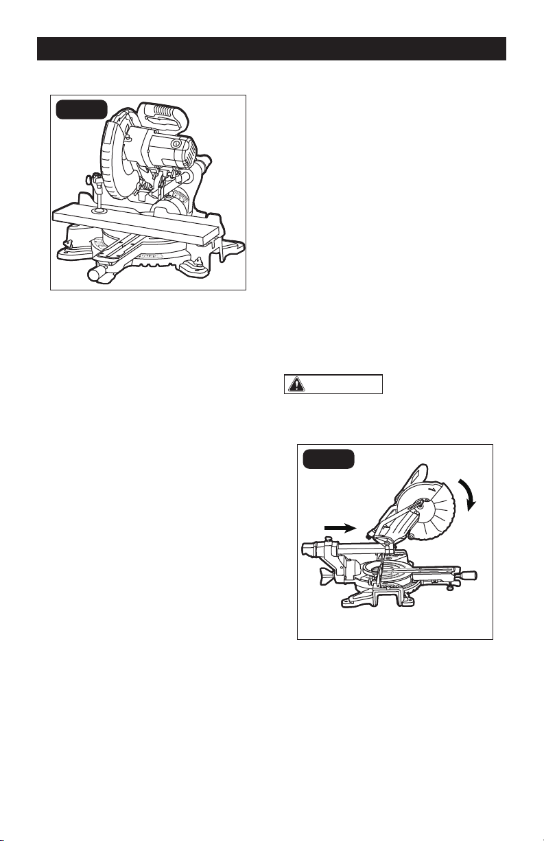
BEVEL CUT (FIG.14)
A bevel cut is a cut made across the grain
of the workpiece with the blade at an angle
to the workpiece. A straight bevel cut is
made with the miter table set at the 0°
position and the saw arm set at a bevel
angle between 0° and 45° left.
1. Pull out extension bars if the workpiece
is relatively long.
2. Loosen the bevel locking knob and tilt
the saw arm to the desired bevel angle,
as indicated on the bevel scale. The
blade can be positioned at any angle
from a 90° straight cut (0° on the scale)
to a 45° left.
3. Tighten the bevel locking knob to secure
the saw arm in position.
4. Follow procedures for either chop cuts
or slide cuts.
NOTICE: Be sure to move sliding fence
away from the blade to avoid cutting into
the fence when bevel cutting. The sliding
fence may need to be removed when
preforming extreme bevel cuts and most
compound cuts.
FIG. 14
Page 23
COMPOUND CUTS (FIG.15)
FIG. 15
A “compound cut” is a cross-cut made
with the blade both at a miter angle and at
a bevel angle. Because it may take several
tries to obtain the desired compound angle,
perform test cuts on scrap material before
making your cut.
1. If the cutting process is interfered by
the sliding fence, just remove the sliding
fence (refer to “INSTALL/REMOVE THE
SLIDING FENCE” section).
2. Properly position workpiece. Make sure
workpiece is clamped firmly against the
table or the fence.
3. Set miter and bevel angles according to
the instructions for miter and bevel cuts.
4. Follow the procedures for chop cuts or
slide cuts.
5. Wait until blade comes to a complete
stop before returning head assembly
to the raised position and/or removing
workpiece.
CUTTING GROOVES (FIG.16)
The depth-stop adjustment is a feature used
when cutting grooves in the workpiece. The
depth adjustment is used to limit the blade
depth. A groove should be cut as a slide cut.
1. Loosen the lock nut. Rotate the depth
adjustment screw to the desired cutting
depth, and retighten the lock nut.
2. Plug the saw into an electrical socket.
3. Cut the two outside edges of the groove.
4. After cutting a groove, turn off the saw
and wait for blade to stop.
5. To create the groove, use a wood chisel
or make multiple passes with the router
to remove the material between the
outside edges.
FIG. 16a
Depth-stop
Platform
Depth
Adjustment
Screw
Lock Nut
FIG. 16b
Workpiece
Outside
Grooves
Chisel Cut
OPERATION
Page 24
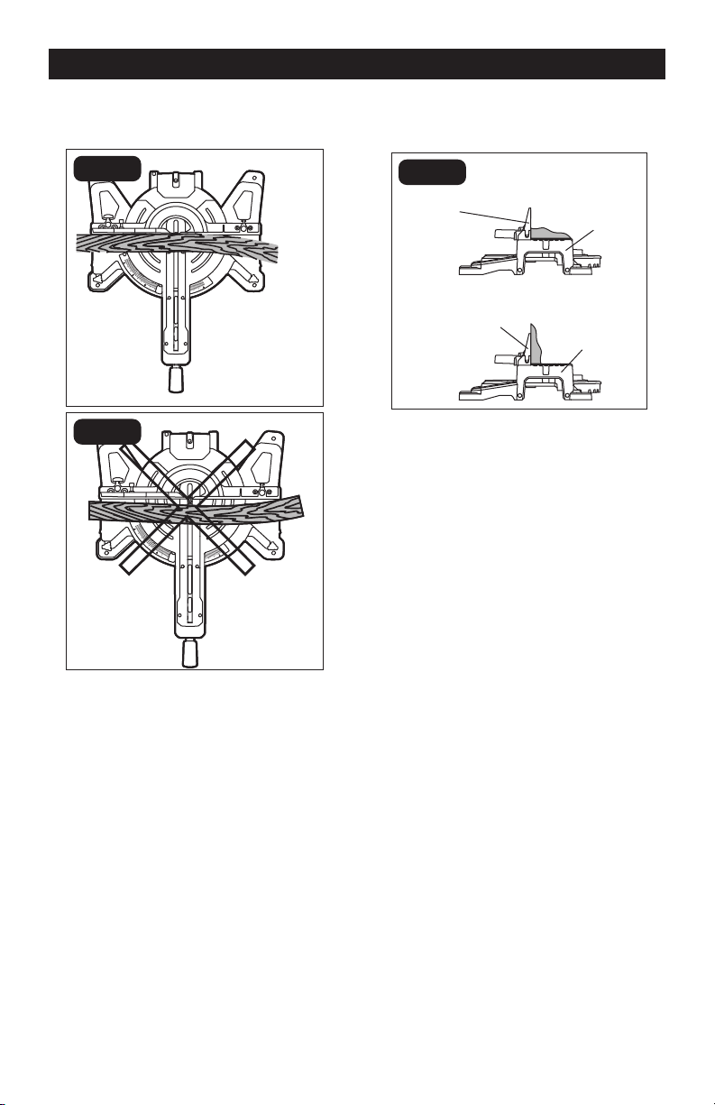
CUTTING WARPED MATERIAL
(FIG.17)
FIG. 17a
Right
Top View
FIG. 17b
Wrong
Top View
When cutting warped material, be certain
that the material to be cut is positioned on
the miter table with the convex side against
the fence (Fig.17a). If the warped material is
positioned the wrong way (Fig.17b), it will
pinch the blade near the end of the cut.
CUTTING BASE MOULDING
(FIG.18)
FIG. 18
Fence
Miter at 0°,
Bevel at 45°
Miter at 45°,
Bevel at 0°
Miter Saw
Fence
Miter Saw
Molding Lying Flat On
Miter Table (Before
Clamping)
Molding Standing Up Against
Fence (Before Clamping)
Base moldings and many other moldings
can be cut on a miter saw. The setup of
the saw depends on the base molding
characteristics and applications, as shown.
Perform practice cuts on scrap materials to
achieve best result.
1. Always make sure that the molding
rests firmly against the fence and table
(Fig.18). Use the work clamp provided or
use C-clamps (available separately), and
place tape on the area being clamped to
avoid marks on the workpiece.
2. Reduce splintering by taping the cut
area prior to making the cut. Mark the
cutting line directly on the tape.
3. Splintering typically happens due
to incorrect blade style, dull blade,
thinness of workpiece, or improperly
dried wood.
4. Place the workpiece flat on the miter
table with one edge securely against the
fence.
5. Align your pencil line with the straight
line from the worklight.
6. When cutting long workpieces, use
extension bars for extra support.
7. Carefully follow all instructions for
applicable miter, bevel or compound
cuts.
OPERATION
Page 25
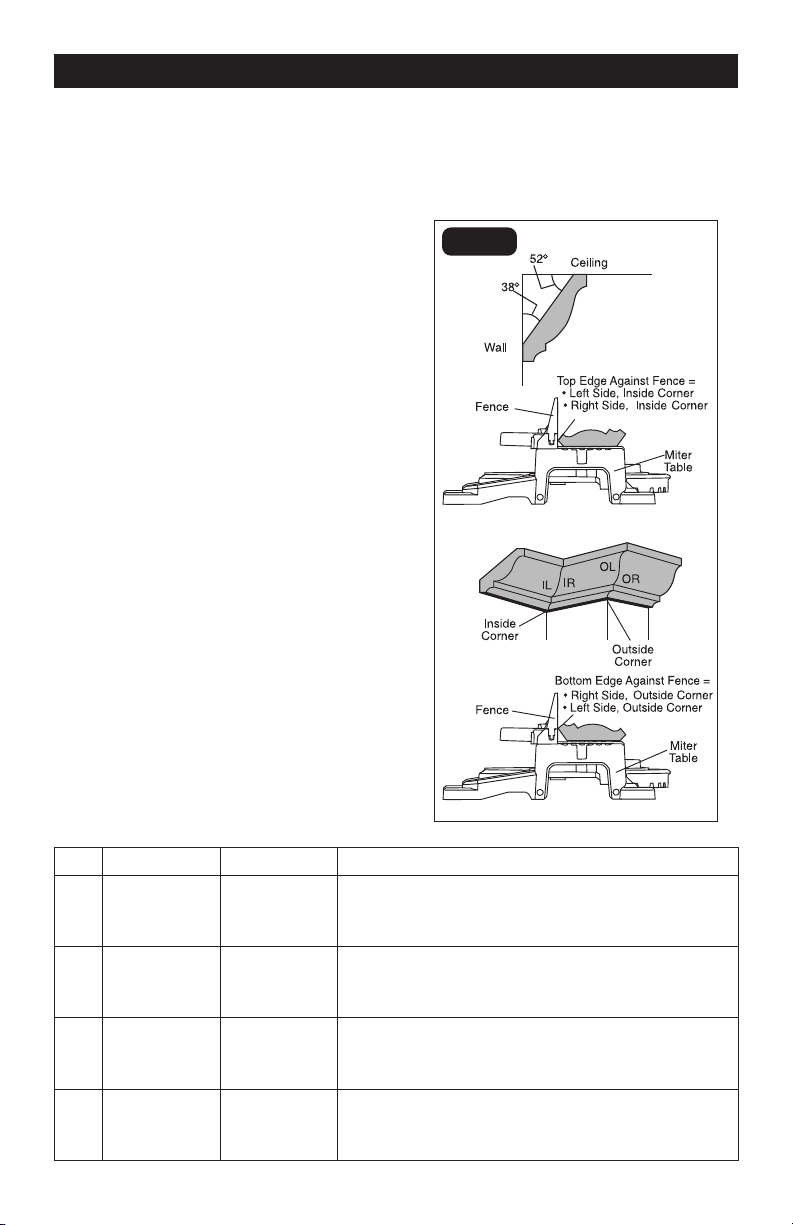
CUTTING CROWN MOULDING
(FIG.19)
Your miter saw is ideal for cutting crown
molding. To fit properly, crown molding
must be compound-mitered with extreme
accuracy. To fit flat against the ceiling and
wall, the sum of the angles of the crown
molding’s two connecting surfaces must
equal 90°.
When setting the bevel and miter angles for
compound miter cuts, remember that the
settings are interdependent; changing one
also changes the other.
Keep in mind that, because it is very easy
for the angles of crown molding to shift
slightly, all settings should be tested on
scrap molding. Also, most walls do not have
angles of precisely 90°; therefore, you will
need to fine-tune your settings.
When cutting crown molding, the bevel
angle should be set at 33.9°, and the miter
angle should be set at 31.6° either left or
right, depending upon the desired cut for
the application.
See the following table for correct angle
settings and correct positioning of the
crown molding on the miter table.
Crown molding has a high top rear spring
angle (the section that fits flat against the
ceiling) of 52° and a bottom rear spring
angle (the section that fits flat against the
wall) of 38°.
FIG. 19
OPERATION
Key Miter Setting Bevel Setting Type of cut
IL 31.6°Right 33.9° Inside corner - Left side
1. Position top of the molding against the fence.
2. LEFT side is finished piece.
IR 31.6° Left 33.9° Inside corner - Right side
1. Position bottom of the molding against the fence.
2. LEFT side is finished piece.
OL 31.6° Left 33.9° Outside corner - Left side
1. Position bottom of the molding against the fence.
2. RIGHT side is finished piece.
OR 31.6° Right 33.9° Outside corner - Right side
1. Position top of the molding against the fence.
2. RIGHT side is finished piece.
Page 26
WARNING:
When servicing, use
only identical replacement parts. Use of
any other parts may create a hazard or
cause product damage.
WARNING:
To avoid serious
personal injury, always unplug the power
from the product when cleaning or
performing any maintenance.
Periodic maintenance allows for long life
and trouble-free operation. A cleaning,
lubrication and maintenance schedule
should be maintained. As a common
preventive maintenance practice, follow
these recommended steps:
1. When work has been completed, clean
the tool to allow smooth functioning of
the tool over time.
2. Use clean damp cloths to wipe the tool.
3. Check the state of all electrical cables.
4. Keep the motor air openings free of oil,
grease and sawdust or woodchips, and
store the tool in a dry place.
5. Be certain that all moving parts are well
lubricated with silicone or light oil spray,
particularly after lengthy exposure to
damp and/or dirty conditions. Do not
use grease, because it tends to attract
and hold sawdust.
6. Check for loose screws, misalignment
or binding of moving parts, or any other
condition that may affect the operation.
7. If abnormal vibration or noise occurs,
turn the saw off immediately, and have
the problem corrected before further
use.
SAWDUST
Periodically, sawdust will accumulate
under the table and base. This could cause
difficulty in the movement of the table when
setting up a miter cut. Frequently blow out
or vacuum up the sawdust.
LOWER BLADE GUARD
Do not use the saw without the lower blade
guard.
The lower blade guard is attached to the
saw for your protection. Should the lower
guard become damaged, do not use the
saw until the damaged guard has been
replaced. Check regularly to make sure the
lower guard is working properly. Clean the
lower guard of any dust or buildup with a
damp cloth.
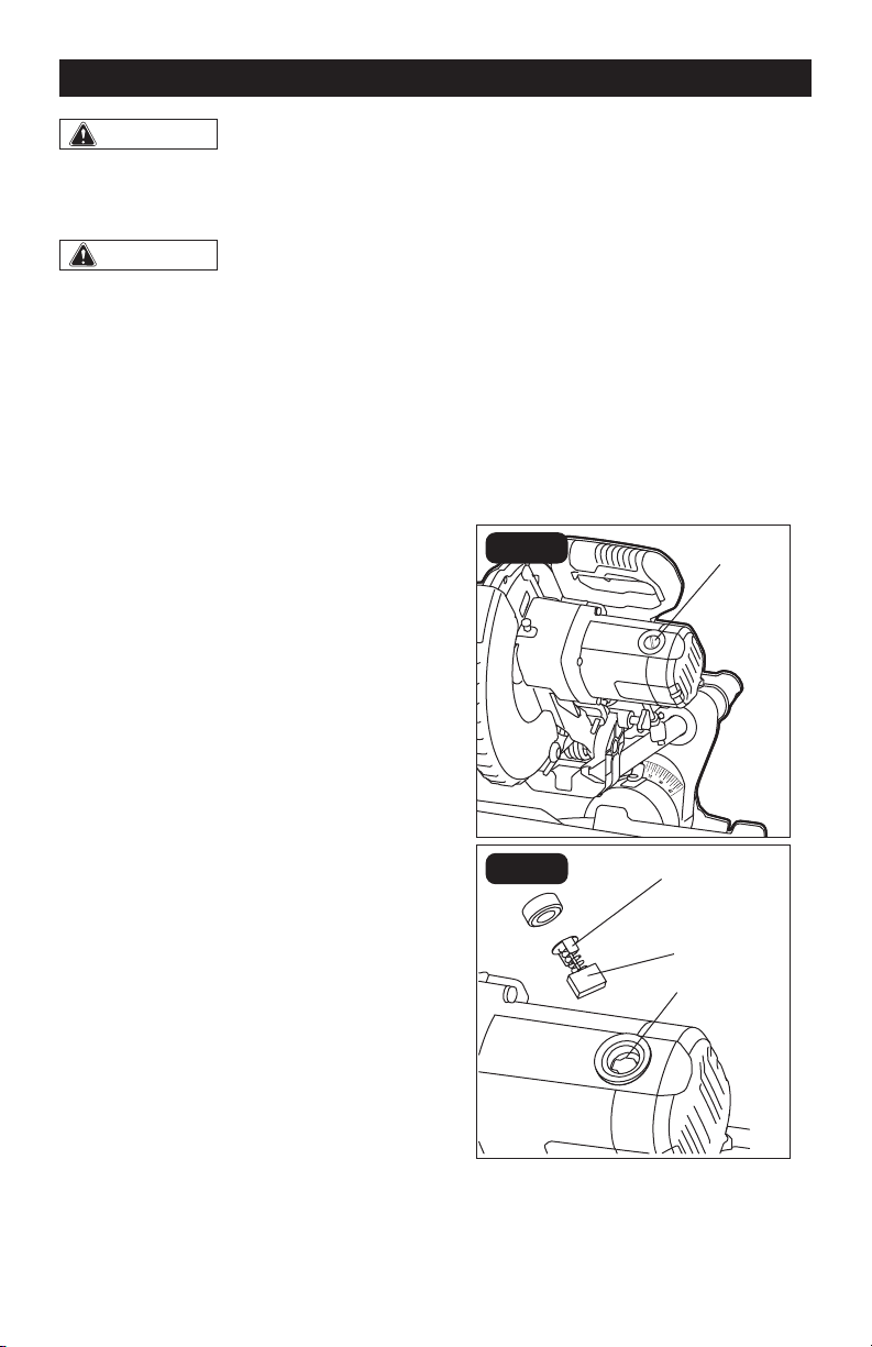
REPLACING CARBON BRUSHES
(FIG.20)
FIG. 20a
Plastic Cap
FIG. 20b
Carbon
Brush
Ears
Slot
The factory installed carbon brushes in the
motor assembly. Inspect them regularly.
MAINTENACE
Page 27
1. First unplug the saw before inspecting
or replacing brushes.
2. Replace both carbon brushes when
either has less than 1/4” (6 mm) of
carbon remaining, or if the spring or wire
is damaged or burned.
3. Using a slotted screwdriver, remove the
black plastic cap on each side of the
motor housing, and carefully withdraw
the spring-loaded brush assemblies.
Keep brushes clean and sliding freely in
their guide channels.
NOTICE: To reinstall the same brushes,
make sure the brushes go back in the same
way they came out. This will avoid a break-
in period.
4. Insert new brush assemblies into guide
channels, with the carbon part going in
first, being certain to fit the two metal
“ears” into their slots in the channel.
5. Remember to replace both end caps
after inspecting or servicing brushes.
Tighten the caps snugly, but do not
over-tighten.
6. The saw should be allowed to “RUN
IN” (run at no-load without a blade) for
5 minutes before use to seat the new
brushes properly.
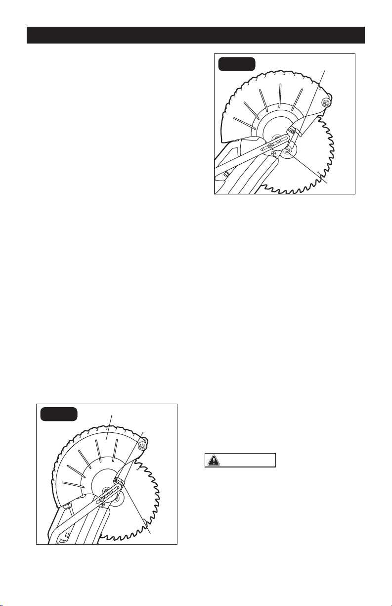
REMOVE THE BLADE (FIG.21)
FIG. 21a
Arbor Guard
Screw
Lower Blade Guard
Arbor
Guard
FIG. 21b
Outer Flange
Arbor
Screw
1. Unplug the tool.
2. Raise the saw head, lift and hold lower
blade guard to expose the arbor guard
screw.
3. Loosen the arbor guard screw with a
phillips screwdriver (included) to a point
that the arbor guard can be lifted.
4. Lift and hold the lower blade guard up,
and rotate the arbor guard to expose the
arbor screw.
5. Press and hold the spindle-lock button,
and rotate the blade at the same time
until it locks into position.
6. Use the blade phillips screwdriver
(included) to turn the arbor screw
clockwise, and then remove the arbor
screw.
7. Remove the outer flange and the blade.
Wipe the flanges and spindle to remove
any dust and debris.
INSTALL THE BLADE (FIG.22)
WARNING:
ONLY USE 10” (254
mm) SAW BLADES WITH 5/8” (15.9 mm)
ARBOR HOLES. SPEED RATING MUST BE
AT LEAST 5000 RPM.
1. Unplug the miter saw before changing/
installing the blade.
2. With the arm raised, and the lower blade
guard raised, place the blade onto the
arbor shaft. Match the arrow on the
blade with the arrow on the upper blade
MAINTENACE
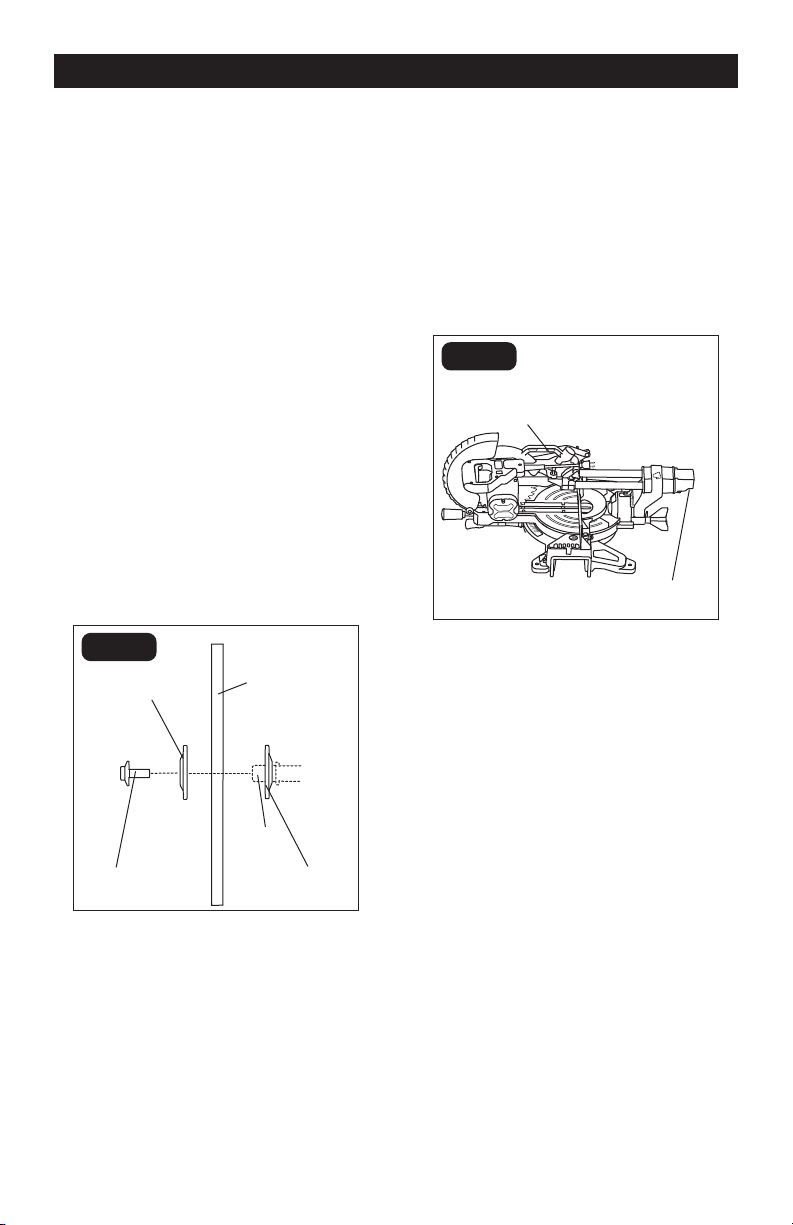
Page 28
guard. Make sure that the blade teeth
are pointing downward.
3. Place the outer flange against the blade
and on the arbor. Thread the blade bolt
onto the arbor in a counterclockwise
direction.
4. Place the phillips screwdriver into the
blade bolt.
5. Press the spindle-lock button, holding
it in firmly while turning the blade
counterclockwise. When spindle lock
engages, continue to press it in while
tightening the arbor screw securely.
6. Pull the arbor guard to its original
position until the slot in the arbor guard
engages with the arbor guard screw
(FIG.21a). While holding the lower blade
guard, tighten the arbor guard screw
with a phillips screwdriver (included).
7. Verify that the operation of the lower
blade guard does not bind or stick.
8. Be sure the spindle lock is released so
the blade turns freely before operating
FIG. 22
Outer Flange
Arbor
Shaft
Arbor
Screw
Inner
Flange
Saw
Blade
TRANSPORT THE SAW (FIG.23)
In order to conveniently carry the miter saw
from place to place, a lifting handle has been
included on the top of the saw and hand
indentation at the end cap of sliding rail.
NOTICE: When transporting the miter saw,
the slide rail and the saw head should
always be locked in position.
FIG. 23
Indentation
Lifting
Handle
MAINTENACE

Page 29
PROBLEM POSSIBLE CAUSE SOLUTION
Brake does not
stop blade within 10
seconds.
1. Motor brushes not sealed or
lightly sticking.
1. Inspect/clean/
replace brushes. See
MAINTENANCE section.
2. Motor brake overheated from
use of defective or wrong
size blade or rapid ON/OFF
cycling.
2. Use a recommended blade.
3. Arbor screw is loose. 3. Retighten the arbor screw.
Motor does not start. Brush is worn. Replace brushes. See
MAINTENANCE section.
Brush sparks
excessively when
switch is released.
Brush worn / damaged. Replace brushes. See
MAINTENANCE section.
Angle of cut is
inaccurate.
1. Miter table unlocked. 1. Use miter locking knob to
tighten the miter table.
2. Too much sawdust under
table.
2. Vacuum or blow out dust.
WEAR EYE PROTECTION!
Cutting arm cannot
fully raise or blade
guard cannot fully
close.
1. Sawdust buildup. 1. Clean and lubricate moving
parts.
2. Lock-down pin doesn’t
release.
2. Unlock the lock-down pin.
Blade binds, jams or
burns wood.
1. Improper operation. 1. See OPERATION section.
2. Dull blade. 2. Replace blade.
3. Improper blade. 3. Replace blade.
4. Warped blade. 4. Replace blade.
Saw vibrates or
shakes.
1. Saw blade damaged. 1. Replace blade.
2. Saw blade loosened. 2. Tighten arbor screw.
Light line projection is
hard to see.
1. Light in work area is too
bright.
1. Move the miter saw to the
work area with proper light.
2. Sawdust on the LED
worklight cap or lower blade
guard.
2. Clean the LED worklight cap
or lower blade guard with a
soft, dry brush.
TROUBLESHOOTING

Page 30
SAVE YOUR RECEIPTS
THIS WARRANTY IS VOID WITHOUT THEM
30-DAY MONEY BACK GUARANTEE:
This PERFORMAX
®
brand power tool carries our 30-Day Money Back Guarantee. If
you are not completely satisfied with your PERFORMAX
®
brand power tool for any
reason within thirty (30) days from the date of purchase, return the tool with your
original receipt to any MENARDS
®
retail store, and we will provide you a refund – no
questions asked.
2-YEAR LIMITED WARRANTY:
This PERFORMAX
®
brand power tool carries a 2-Year Limited Warranty to the original
purchaser. If, during normal use, this PERFORMAX® power tool breaks or fails due
to a defect in material or workmanship within two (2) years from the date of original
purchase, simply bring this tool with the original sales receipt back to your nearest
MENARDS
®
retail store. At its discretion, PERFORMAX
®
agrees to have the tool or
any defective part(s) repaired or replaced with the same or similar PERFORMAX®
product or part free of charge, within the stated warranty period, when returned by
the original purchaser with original sales receipt. Notwithstanding the foregoing,
this limited warranty does not cover any damage that has resulted from abuse or
misuse of the Merchandise. This warranty: (1) excludes expendable parts including
but not limited to blades, brushes, belts, bits, light bulbs, and/or batteries; (2) shall
be void if this tool is used for commercial and/or rental purposes; and (3) does not
cover any losses, injuries to persons/property or costs. This warranty does give
you specific legal rights and you may have other rights, which vary from state to
state. Be careful, tools are dangerous if improperly used or maintained. Seller’s
employees are not qualified to advise you on the use of this Merchandise. Any oral
representation(s) made will not be binding on seller or its employees. The rights
under this limited warranty are to the original purchaser of the Merchandise and
may not be transferred to any subsequent owner. This limited warranty is in lieu
of all warranties, expressed or implied including warranties or merchantability and
fitness for a particular purpose. Seller shall not be liable for any special, incidental,
or consequential damages. The sole exclusive remedy against the seller will be for
the replacement of any defects as provided herein, as long as the seller is willing or
able to replace this product or is willing to refund the purchase price as provided
above. For insurance purposes, seller is not allowed to demonstrate any of these
power tools for you.
For questions / comments, technical assistance or repair parts –
Please Call Toll Free at: 1-866-858-2664 (M-F 8:30am-5:00pm Est.)
10’’ Sliding Compound Miter Saw
WARRANTY

11/2019
© 2019 Menard, Inc., Eau Claire, WI 54703