240-3680
Owner's Manual
Voltage
Current rating
Blade Speed
Blade Diameter
Arbor Size
Positive Miter Stops
Miter Angle
Power Cord
Weight 21 lbs
10ft
47 degree Left/ 47 degree Right
0, 15, 22.5, 31.6 & 45 degree
5/8"
7-1/4" 24 tooth carbide tipped
5000 RPM (No-Load Speed)
9.5 Amps
120 VOLTS AC, 60Hz
Need Assistance ?
Call us on our toll free customer support line : 1-866-915-8626
Technical questions
Replacement parts
Parts missing from package
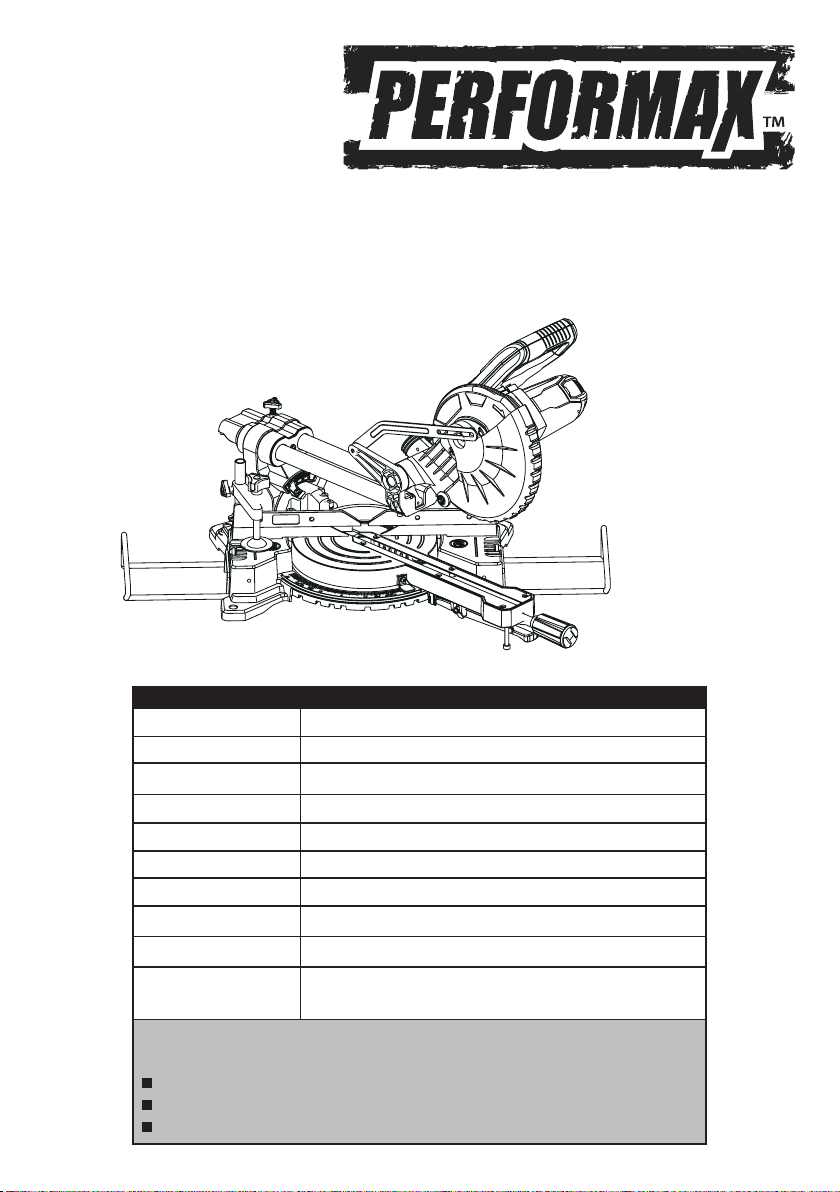
PRODUCT SPECIFICATIONS
7-1/4 " SLIDING
COMPOUND MITER SAW
Cutting Capacity
90° cross cut 2-3/8" x 11-1/2"
45° miter cut 2-3/8" x 7-7/8"
45° bevel cut 1-1/2" x 11-1/2"
45° miter/bevel cut 1-1/2"" x 7-5/8"

IMPORTANT SAFETY INSTRUCTIONS .......................
.......
Page 3
SAFETY PRECAUTIONS FOR COMPOUND MITER SAW
Page 4
FUNCTIONAL DESCRIPTION .....................................Page 5
OPERATING PROCEDURES .......................................Page 6
MAINTENANCE ........................................................Page 7
PARTS LIST .............................................................Page 11
ASSEMBLY DRAWING ..............................................Page 12
WARRANTY .............................................................Page 13
TABLE OF CONTENTS

Consider work area environment. Don't use power tools in damp, wet, or poorly lit locations.
Don’t expose tools to the rain. Keep the work area well lit. Don't use tools in the presence of
flammable gases or liquids.
Keep children and bystanders away. All children should be kept away from the work area.
Don’t let them handle machines, tools or extension cords. Bystanders can be a distraction and
can be injured.
Grounded tools must be plugged into an outlet that is properly installed and grounded, a
low-resistance path to carry electricity to the ground away from the operator, should the tool
malfunction electrically. Do not remove the grounding prong from the plug or alter the plug in
any way. If in doubt as to whether the outlet is properly grounded according to code, check with
a qualified electrician.
Observe proper precautions regarding double insulation. This tool is double insulated. It is
equipped with a polarized plug. One blade is wider than the other, so it will fit into a polarized
outlet only one way. If you have difficulty inserting the plug, try reversing it. If it still doesn't fit,
do not alter the plug; have a qualified electrician install a polarized outlet.
Guard against electric shock. Prevent body contact with grounded surfaces: pipes, radiators,
ranges, and refrigerator enclosures. When your body is grounded the risk of electric shock
increases. When working wherever “live” electrical wires may be encountered, try to ascertain
whether there is a danger of shock. Do not touch any metal parts of the tool while using it. Hold
the tool only by the plastic grip to prevent electric shock if you contact a live wire.
Do not misuse the cord. Never carry your tools by the cord or pull on the cord to unplug it.
Protect the cord from potential sources of damage: heat, oil & solvents, sharp edges, or moving
parts. Replace damaged cords immediately.
When working outdoors, use an outdoor-rated extension cord. An extension cord rated for
outdoor use must be marked “W-A" or “W”.
Do not expose electrical power tools to moisture. Rain or wet conditions can cause water to
enter the tool and lead to electric shock.
Ensure the extension cord you use is of sufficient gauge for its length.
3
IMPORTANT SAFETY INSTRUCTIONS
WARNING:
When using electric tools, machines or equipment, basic safety precautions should always
be followed to reduce the risk of fire, electric shock, and personal injury.
Read all instructions before using this tool!
Keep work area clean. Cluttered areas invite injuries.
Store idle equipment. Store equipment in a dry area to inhibit rust. Equipment also should be
in a high location or locked up to keep out of reach of children.
Recommended Minimum Wire Gauge for Extension Cords
Amps
from
Tool Nameplate
25’ length 50’ length 75’ length 100’ length 150’ length 200’ length
0-5 amps
5.1-8 amps
8.1-12 amps
12.1-15 amps
15.1-20 amps

4
SAFETY PRECAUTIONS FOR COMPOUND MITER SAW
Don't force the tool. It will do the job better and more safely at the rate for which it was intended.
Use the right tool. Don't force a small tool or attachment to do the work of a larger industrial
tool. Don't use a tool for a purpose for which it was not intended.
Dress properly. Don't wear loose clothing or jewelry; they can be caught in moving parts.
Protective, non-electrically conductive gloves, protective eyewear and non-skid footwear are
recommended. Wear protective hair covering to contain long hair and keep yourself from harm.
Use eye protection. Use a full-face mask if the work you're doing produces metal filings, dust or
wood chips. Goggles are acceptable in other situations. Wear a clean dust mask if the work
involves creating a lot of fine or coarse dust.
Secure work. Use clamps or a vise to hold the work, this frees both hands to operate the tool.
Dont overreach. Keep proper footing and balance at all times. Do not reach over or across
machines that are running.
Maintain tools. Keep tools sharp and clean for better and safer performance. Follow instructions
for lubricating and changing accessories.
For safe performance, keep handles dry, clean and free
from oil and grease.
Avoid unintentional starting. Be sure the switch is in the off position before plugging in.
Always check and make sure to remove any adjusting keys or wrenches before turning the
tool on. Left attached, these parts can fly off a moving part and result in injury.
Do not use the tool if it cannot be switched on or off. Have your tool repaired before using it.
Disconnect the plug from the power source before making any adjustments. Changing attachments
or accessories can be dangerous if the tool could accidentally start.
Stay alert. Watch what you are doing & use common sense. Don't operate any tool when you
are tired.
Check for damaged parts. Before using this tool, any part that is damaged should be carefully
checked to determine that it will operate properly and perform its intended function. Check for
alignment of moving parts, binding of moving parts, breakage of parts, mountings, and other
conditions that may affect its operation. Inspect screws and tighten any ones that are loose. Any
part that is damaged should be properly repaired or replaced by an authorized service center
unless otherwise indicated elsewhere in the instruction manual. Have defective switches replaced
by an authorized service center. Don't use the tool if switch does not turn it on and off properly.
Replacement parts. When servicing, use only identical replacement parts.
Service and repairs should be made by qualified repair technicians at an authorized repair
center. Improperly repaired tools could cause serious shock or injury.
Wood only. The saw is designed for woodcutting only.
Damaged or warped saw blades should not be used. They are out of balance and could cause
further damage to the saw and possible personal injury.
Use only with guard in place. The guard protects the operator from cutting debris as well as
from broken pieces of the blade, should it break in use.
Replace the table insert when worn. Excessive tear-out increases the likelihood of injury
from flying debris. When setting the saw at a new angle, check that the blade does not cut into
the table insert, rear fence, or another part of your saw.
Always use the blade wrench to tighten the saw blade onto the arbor.
Connect your miter saw to a dust collecting device if possible. If not, use the dust bag that
comes with the tool and empty it regularly.
Use a saw blade suited to the cutting job and material to be cut.
Always use table extensions and clamps to support the material when sawing long work pieces.
The material should be placed firmly against the fence and table. The turning of the saw
blade should force it down against the table and rearward against the fence during the cut.
Movement of the workpiece during the cut may cause the blade to jam and create a kickback.
When this happens, the cutting head may jump out of your hand or the workpiece may fly loose
and cause serious injury.
Do not start the saw with the blade in contact with any surface. This may cause the saw to
bounce or kickback violently and could cause injury.
If making a cut using one hand to hold the saw, ensure the free hand is clear of cutting area.
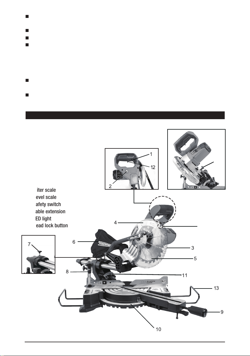
1. Trigger
2. LED light switch
3. Lower blade guard
4. Upper blade guard
5. Saw blade
6. Dust bag
7. Sliding lock knob
8. Hold-down clamp assembly
9. Miter locking handle
10. Miter scale
11. Bevel scale
12. Safety switch
13. Table extension
14. LED light
15. Head lock button
5
FUNCTIONAL DESCRIPTION
14
15

Mount the hold-down clamp on one side of fence. Insert shaft of the hold-down clamp into the
mounting hole and tighten the hold-down clamp retainer screw to affix the shaft of the hold-down
clamp.
Adjust position of the hold-down clamp bracket according to the workpiece thickness and
shape. Tighten the screw to fix the bracket in place.
Make sure that when the handle is lowered, beveled or angled in any position, no part of the
tool contacts the hold-down clamp.
■ Before use, release the head lock button and raise the handle.
■ Before turning on, confirm that the saw blade does not touch the work piece or the vise at
any position.
■
When cutting, press the handle down slowly. Do not force the handle, as this may cause damage
to your saw.
■ Before starting to cut, confirm that the saw blade has attained full speed. After cutting is
complete wait until the rotation of the blade stops completely before lifting the handle to its top
position.
■ For your safety, remove chips, small pieces, etc. from the table top before operation.
■ For best performance, always keep saw blade clean and sharp.
After unpacking, reading the instructions, attaching the machine to the workbench,
and checking that all attachments are correctly installed, you can use your saw. Be
sure to wear the appropriate protective equipment.
1. Check to ensure everything is correctly attached, screws are fastened, and all adjusting keys
and wrenches are removed.
2. Connect the saw to power.
3. Unlock the saw from its various storage and shipping positions.
4. Push forward the safety switch (#12 on page 5). Pressing the trigger switch (#1 on page 5)
will start the saw.
6
OPERATING PROCEDURES
WARNING:
For safe and accurate cuts, fix workpiece firmly into cutting position with hold-down damp,
otherwise the tool and workpiece may be damaged.
WARNING:
Before plugging In, confirm that the trigger is normal. If the locking button is not depressed,
do not pull the trigger with force as this may cause severe damage to the switch.
Clamping Workpiece:
Remember:
Start Up
Using Your Saw
Caution: Be sure the saw is disconnected from its power source before making any
repairs or performing maintenance!

To begin cutting, lower the cutting head. The lower blade guard opens automatically.
After cutting, allow the head to come back up. The guard will close automatically.
The saw will stop when you release the trigger switch in the handle.
■ Inspect the cord regularly and have it replaced by an authorized repair facility if it is
damaged.
■
Check the brushes occasionally (after about 50 hours of use) and replace if worn. The brushes
can be replaced by removing the motor brush cap.
The brushes and their springs could jump out of the holders- be careful not to lose them. Inspect
the brushes. If the contact surface is not smooth, or it is worn or heavily used, replace both
brushes. Insert the new brushes and springs in their holders and re-fasten the cap.
■ The plastic kerf plate table insert should be replaced if damaged to reduce the risk of chips
lodging in the slot and catching in the blade.
MAINTENANCE
Modes of Use
The head is locked in the upright position. To unlock the table rotation, unscrew the locking
handle and press on the miter detent spring lever with your thumb. Move the table rotation to
the left or right up to 47° left & 47° right. The miter detent spring lever, if released, will stop the
table at detents at 0°, 15°, 22.5°, 31.6°, & 45° left and right. Use the locking handle to lock the
table at the desired angle, especially those between the detents.
Miter Cut:
To unlock the head angle (bevel) adjustment, loosen the bevel lock handle at rear of the saw.
Lock it when the blade is tilted at the desired angle. The table rotation is locked at 0°.
Bevel Cut:
Unlock and move the table rotation to the left or right as in miter cuts above. Using the lever at
the back of the saw, unlock the head and bevel it to any position from 0° - 45° left, then lock it
in place.
Compound Cut:
The head is locked in the upright position. The table rotation is locked at 0°.
This is a good setting for simple 90° crosscuts.
Chop Cut:
7
Note: At extreme positions,
the
hold-down clamp should be moved to the right side
of the table to prevent interfering with the movement of the cutting head. Always
check before making the cut if there is any potential interference from the clamp or
any other part of the machine.
Note: Even though the angles are marked on the machine, it is always a good idea
to check them by making a trial cut. See Aligning Miter and Bevel, below.
■
■
■

8
■
Keep the vents clear of dust and debris. This will help prevent possible electrical shorts and ensure
proper cooling.
■
Keep the tool housing and handle dean and free of oil and grease by using mild soap and a damp
(not wet) cloth.
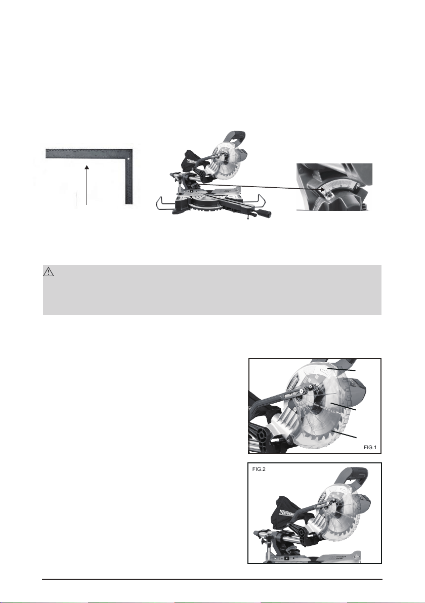
■ Set the bevel angle at 0 degrees.
■ Loosen the locking handle.
■ Depress the miter detent spring lever.
■ Turn the saw table so that the arrow in the kerf plate points to 0 degrees, then move the table
slightly clockwise and counter-clockwise and let the miter detent spring lever fit into the groove
( it doesn't matter if needle doesn't indicate 0 degrees ).
■ Loosen the four hex bolts behind the fence with the blade socket wrench.
■ Lower the saw head and lock it in place with the head lock button.
■ Make sure the Fence is perpendicular (at a 90° angle) to the Saw Blade,using carpenter
square.(can be purchased at any hardware store, and comes in various sizes.)
■ Tighten the hex bolts in the fence firmly.
■ Confirm that the arrow in the kerf plate points to 0 degrees. If not, loosen the two screws in
the bottom of the miter detent spring lever and adjust accordingly.
Miter Angle
A. Vertical stop: 0 degrees adjustment
■ Lower the saw head to its lowest position and lock it with the head lock button.
■ Loosen the bevel lock handle on the back of the saw.
■ Check that the blade is perpendicular to the table as measured, using a small carpenter
square If not:
1. Use an open-end wrench to loosen the hex lock nut and then turn the hex stop bolt at the
back right side of the table.
2. Turn the bolt counter-clockwise and the 0 point moves left, closing the angle. Turning it
clockwise moves the 0 point to the right, opening the angle.
3. When you have established the vertical stop correctly, tighten the lock nut down to hold the
setting.
4. Make sure that the needle points to 0 degrees on the scale. If not, loosen the screws and
adjust the needle.
B. Bevel stop: 45 degrees adjustment
■ Lower the saw head to ifs lowest position and lock it with the head lock button.
■ Loosen the bevel lock handle on the back of the saw.
■ Check that the blade is at 45 degrees to the table as measured, using a small carpenter
Bevel Angle
Miters and bevels have been set at the factory. However, use may affect settings. Please use the
following procedures when your tool needs adjustments.
Aligning Miter and Bevel
WARNING:
Prior to performing any assembly and/or adjustment procedures, make sure the Power Cord
of the Miter Saw is unplugged from its electrical outlet. Make sure the unit has compietety
cooled, and wear heavy-duty work gloves.
square. If not:
1. Use an open-end wrench to loosen the hex lock nut and then turn the hex stop bolt at the
back left side of the table.
2. Turn the bolt clockwise and the 45 degrees point moves left, opening the angle. Turning it
counter-clockwise moves the 45 degrees stop to the right, closing the angle.
3. When you have established the 45 degrees stop correctly, tighten the lock nut down to hold
the setting.
4. Make sure that the needle points to 45 degrees on the scale. If not, loosen the screws and
adjust the needle.
1. When replacing the saw blade, make sure the new saw blade has a diameter of 7-1/4", an
RPM rating of at least 6000, an arbor hole of 5/8" diameter.
2.
When mounting the new saw blade, the direction
arrows on the blade correspond with the arrow
on
the upper guard.
A. Upper blade guard
B. Lower blade guard
C. Saw teeth pointing down
(See Figure 1)
3. Put the saw in the upper position.
(See Figure 2)
Replacing Saw Blade
9
Bevel Scale
carpenter square
FIG.1
B
C
A
FIG.2
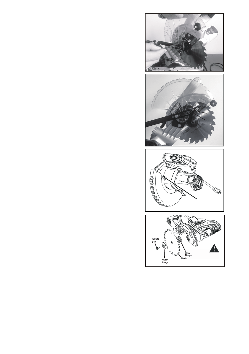
4. Raise the lower blade guard and use supplied
phillips screwdriver to loosen screw almost 7/32".
(See Figure 3 )
5.
The lower blade guard can be held in the up position
by the screw. Push the locating plate upward.
(See Figure 4 )
6.
Depress the spindle lock (F) to keep the saw blade
from turning.
(See Figure 5 )
7. Use the wrench to unscrew and remove the
spindle bolt.
NOTE: The Spindle bolt unscrews in a clockwise
direction. Then, remove the Outer Flange.
(See Figure 6 )
8. Install a New Blade
Make sure to match the direction arrows marked on the new blade with the direction arrows
marked on the upper blade guard. ( Saw teeth should always be pointing downward. )
Replace outer flange.
Tighten spindle bolt securely,using the blade wrench and tightening counterclockwise.
Rotate lower blade guard back into place,replace any screws that were removed, tighten the
screws that hold the upper and lower guard in place, by tightening in clockwise rotation.
Remove cross pin so the saw can be lowered into cutting position.
Disengage spindle lock.
10
F
screw
locating
plate
FIG.5
FIG.4
FIG.3
FIG.6

11
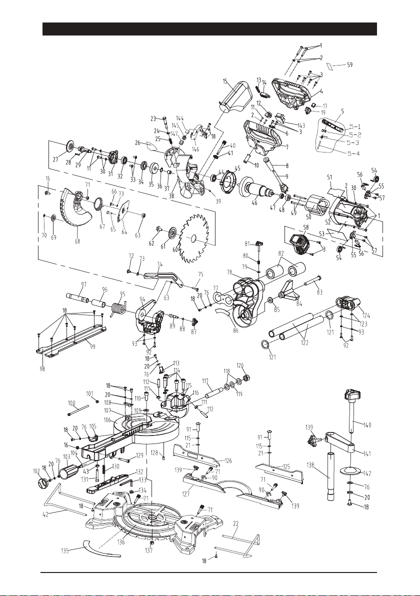
PARTS LIST
Please refer to the schematic drawing on page 12.
1
2
3
4
5
5-1
5-2
5-3
5-4
6
7
8
9
10
11
12
13
14
15
16
18
19
20
21
22
23
24
25
26
27
28
29
30
31
32
33
34
35
36
37
38
39
40
41
42
43
44
45
46
47
17
6
13
10
1
1
1
1
1
1
1
1
1
1
1
5
1
1
1
1
1
18
1
10
2
1
1
1
1
1
1
1
1
8
1
1
2
1
1
1
1
1
1
1
1
1
1
1
1
1
1
1
Cross head screws
Washer
Self -tapping screws
Upper handle
Switch trigger assembly
Switch trigger
Switch trigger key
Spring
Pin
Cord press plate
Lower handle
Cable sheath
Power cord
Inner wire sleeve
Screw
Terminal
Trigger spring
Micro-switch
Dust bag
Shouldder screws
48
49
50
51
52
53
54
55
56
57
58
59
60
61
62
63
64
65
66
67
1
2
1
1
1
1
2
2
2
4
1
1
1
1
1
2
1
1
1
1
Bearing sleeve
Tapping screw
Stator
Rating label
Motor housing
Warning label
Brush spring
Brush holder
Carbor Brush
Tapping screw
End cap
Warning label
Blade
Outter flange
Socket screws
Lock nut
Move guard support
Screws
Shouldder screws
Spring
99
100
101
102
103
104
105
106
107
108
109
110
111
112
113
114
115
116
117
118
1
1
1
1
1
1
1
1
1
1
1
1
2
2
1
4
6
1
1
2
Table insert (Rightt)
Socket screws
Hex nut
Handle cap
Mitre handle
Mitre angle lock rod
Mitre indicator
Turn table
Square nut
Lock plate
Washer
Hex screw
Hex nut
Set screws
Bevel indicator
Hex screw
Spring washer
Table connect block
Rotary shaft
Washer
Screws
LED Switch
Spring washer
Washer
Right extension bar
Spindle lock pin
C ring
69
70
71
72
73
74
75
1
1
4
1
1
1
1
Move guard wheel
Inner tooth washer
Knbo
Shouldder screws
Wave washer
Linkage
Screws
120
121
122
123
124
125
126
1
2
2
2
1
1
1
Locknut
Rubber ring
Guide bar
Washer
Slide end cap
Right sliding fence
Left sliding fence
spindle lock pin spring
Brand label
Inner flange
Flat key
Spindle
Spring washer
Gear box cover
Bearing
Screw
Spindle lock stop plate
Gear
Check ring
copper sleeve
Fix guard
Set screws
Depth adjuster
Knurled nut
Left extension bar
Nut
Bearing
Fan baffle
Armature
Bearing
76
77
78
79
80
81
82
83
84
85
86
87
88
89
90
91
92
93
94
95
96
97
98
1
1
1
1
1
1
2
1
1
1
1
1
1
1
2
2
4
4
1
1
1
1
1
Washer
Bearing cover
Bevel Arm
Washer
Spring
Knob
Linear bearing
Hex bolt
Bevel locker
Washer
Bevel scale
Lock pin knob
O-ring
Lock pin
E-ring
Half round socket screws
Half roud screws
Spring washer
Bracket
Big torsion spring
Spring sleeve
Pivot shaft
Table insert (Left)
127
128
129
130
131
132
133
134
135
136
137
138
139
140
141
142
143
144
145
146
147
1
1
1
1
1
1
1
1
1
1
1
1
3
1
1
1
1
1
1
1
1
Fence
Set screws
Screws
spring
Hex screw
Location push button
Hex key
Hex key store
MITER SCALE
Base
Lock nut
Support pole
Knob
Clamp screw knob
Clamp arm
Clamp
Transformer
LED lamp
Lamp shade
LED lamp cover
Lamp cover
LED Switch cover 68 1Move guard 119 1Wave washer
12
ASSEMBLY DRAWING

13
PERFORMAX
TM
7-1/4 " SLIDING COMPOUND MITER SAW
30-DAY MONEY BACK GUARANTEE:
This PERFORMAX
TM
brand power tool carries our 30-Day Money Back Guarantee. If you are
not completely satisfied with your PERFORMAX
TM
brand power tool for any reason within
thirty (30) days from the date of purchase, return the tool with your original receipt to any
MENARDS
®
retail store, and we will provide you a refund – no questions asked.
For questions / comments, technical assistance or repair parts –Please Call Toll Free at:
1-866-915-8626 (M-F 9am – 5pm).
Distributed by: Menard, Inc., Eau Claire, WI 54703
SAVE YOUR RECEIPTS. THIS WARRANTY IS VOID WITHOUT THEM.
2-YEAR LIMITED WARRANTY:
This PERFORMAX
TM
brand power tool carries a 2-Year Limited Warranty to the original
purchaser. If during normal use, this PERFORMAX
TM
power tool breaks or fails due to a defect
in material or workmanship within two (2) years from the date of original purchase, simply
bring this tool with the original sales receipt
back to your nearest MENARDS
®
retail store.
At its discretion, PERFORMAX
TM
agrees to have the tool or any defective part(s) repaired
or replaced with the same or similar PERFORMAX
TM
product or part free of charge, within
the stated warranty period, when returned by the original purchaser with original sales
receipt. Notwithstanding the foregoing, this limited warranty does not cover any damage
that has resulted from abuse or misuse of the Merchandise. This warranty: (1) excludes
expendable parts including but not limited to driver blades, O rings, blades, brushes, belts,
bits, light bulbs, and/or batteries; (2) shall be void if this tool is used for commercial and/
or rental purposes; and (3) does not cover any losses, injuries to persons/property or costs.
This warranty does give you specific legal rights and you may have other rights, which
vary from state to state. Be careful, tools are dangerous if improperly used or maintained.
Seller’s employees are not qualified to advise you on the use of this Merchandise. Any oral
representation(s) made will not be binding on seller or its employees. The rights under this
limited warranty are to the original purchaser of the Merchandise and may not be transferred
to any subsequent owner. This limited warranty is in lieu of all warranties, expressed or
implied including warranties or merchantability and fitness for a particular purpose. Seller
shall not be liable for any special,
incidental, or consequential damages. The sole exclusive
remedy against the seller will be for the replacement of any defects as provided herein, as
long as the seller is willing or able to replace this product or is willing to refund the purchase
price as provided above. For insurance purposes, seller is not allowed to demonstrate any of
these power tools for you.