COMPACT HIGH POWER 2-CHANNEL AMPLIFIER
Quick Start Guide
Features
• Compact High Power 2-Channel Amplier
• High Current Design
• 2x75 Watts @ 4 Ohms, 2x150 Watts @ 2 Ohms
• 1x300 Watts @ 4 Ohms, Bridged Mono
• 12 dB/Octave Linkwitz-Riley Alignment Crossover
• GTO™ Signal Sense (Great Turn On)
• 2 Line-Level RCA Inputs
• 2 Active Speaker-Level Inputs for OEM integration
• Filled with home-grown audio goodness
2
Quick Start Guide
Important Safety Instructions
1. Read these instructions.
2. Keep these instructions.
3. Heed all warnings.
4. Follow all instructions.
5. Do not use this apparatus near water.
6. Clean only with a dry cloth.
7. Do not block any ventilation openings. Install in accordance with the
manufacturer’s instructions.
8. Do not install near any heat sources such as muers, silencers, exhaust
pipes, or other apparatus (including ampliers) that produce heat.
9. WARNING: Improper installation may lead to permanent injury or death.
Installation of the apparatus must be done with great care by qualied
personnel, to prevent damage to fuel lines, power and other electrical
wiring, hydraulic brake lines, and other systems, that might compromise
vehicle safety.
10. Provide +12V and Ground wiring of sucient size to ensure adequate
current to the amplier. For the ACM-2.300 this means 8 gauge wire or
thicker.
11. Use rubber grommets to protect wiring whenever passing wires through
metal openings or bulkheads.
12. Only use attachments/accessories specied by the manufacturer.
13. Refer all servicing to qualied service personnel. Servicing is required
when the apparatus has been damaged in any way, such as the power in-
put terminals are damaged, liquid has been spilled or objects have fallen
into the apparatus, the apparatus has been exposed to rain or moisture,
does not operate normally, or has been dropped.
14. This apparatus shall not be exposed to dripping or splashing, and no
object lled with liquids, shall be placed on the apparatus.
15. Fuses shall be replaced only with the correct type and fuse value, and
only when the apparatus is powered o.
16. Exposure to high sound pressure levels may lead to permanent hearing
loss. Take every precaution to protect your hearing.
The lightning ash with arrowhead symbol within an equilateral
triangle is intended to alert the user to the presence of uninsulated
“dangerous voltage” within the product’s enclosure, that may be of
sucient magnitude to constitute a risk of electric shock to persons.
The exclamation point within an equilateral triangle is intended to
alert the user of the presence of important operating and mainte-
nance (servicing) instructions in the literature accompanying the
appliance.
Caution: to reduce the risk of electric shock, do
not disassemble the apparatus, other than to
remove the top panel to access the controls.
There are no user-serviceable parts inside. Refer
servicing to qualied personnel.
Recycling notice: If the time comes and this apparatus has fullled
its destiny, do not throw it out into the trash. It has to be carefully
recycled for the good of mankind, by a facility specially equipped
for the safe recycling of electronic apparatii. Please contact your
local or state recycling leaders for assistance in locating a suitable
nearby recycling facility. Or, contact us and we might be able to
repair it for you.
3
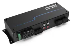
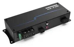
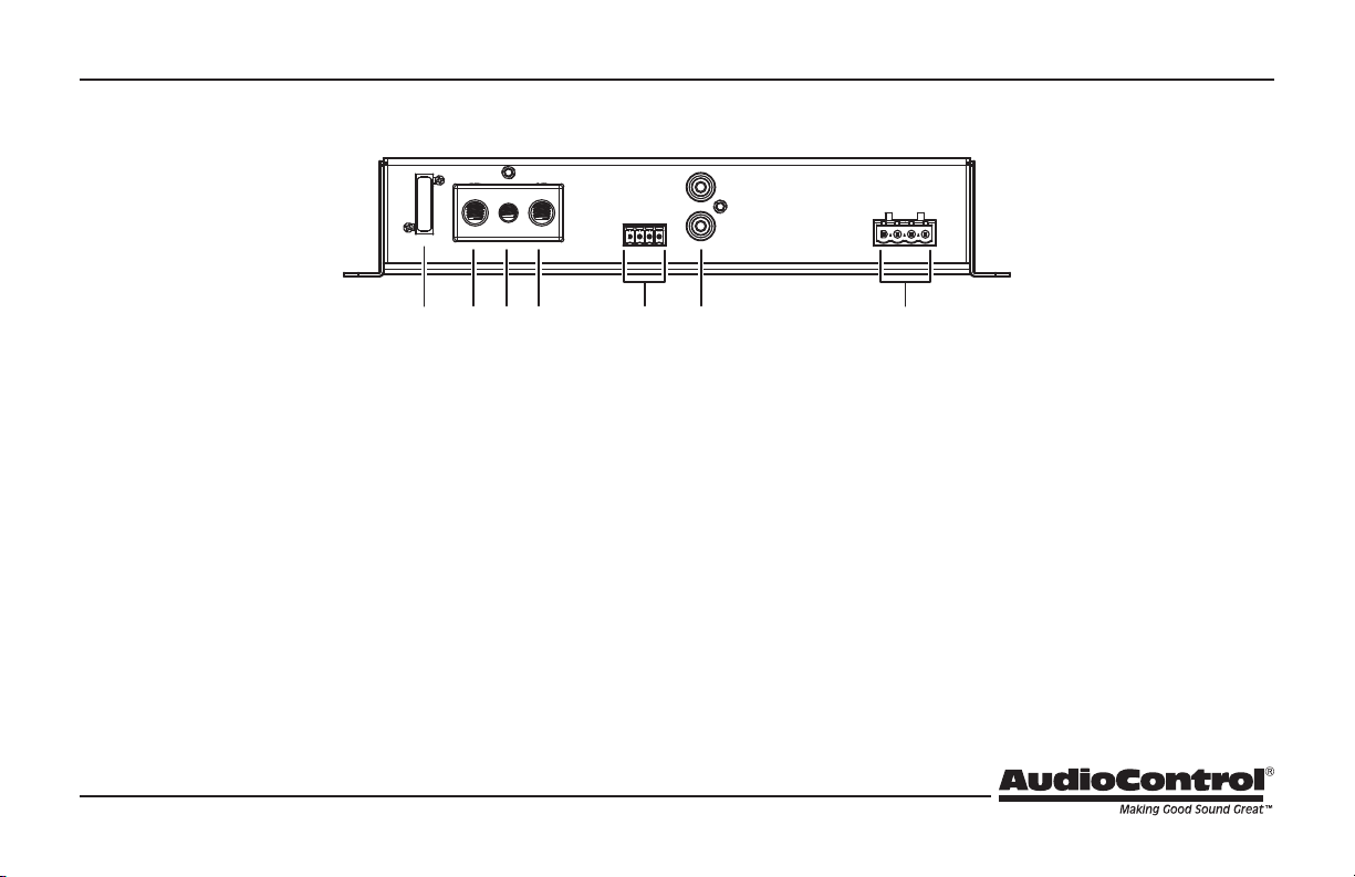
1. Fuse 30A – Replace the fuse only with the exact same style and
Ampere rating. Disconnect 12V power before changing or inspect-
ing the fuse.
2. Power Input Terminal +12V – This screw terminal connects to
the +12V battery binding post of the vehicle. Use quality insulated
wiring of the recommended wire gauge, such as wire gauge 8 or
thicker. Thinner wire may cause an overheating hazard due to the
large currents involved.
3. Remote Power Input Terminal – This screw terminal connects
to the 12V remote trigger output of some head units. When the
head unit is turned on, then the ACM-2.300 amplier will turn on.
Alternatively, you can use the GTO™ feature of the amplier so it
will turn on when an audio signal is detected at the speaker-level
or line-level inputs.
4. Power Input Terminal Ground – This screw terminal connects to
a good ground connection on the vehicle.
5. Speaker-Level Inputs – The ACM-2.300 amplier is supplied with
a standard 4-conductor plug that allows for easy installation and
removal. The speaker-level output from ampliers and factory
installed radios can connect here. Make sure that you follow
the plus and minus polarity markings on the ACM-2.300 and
match it to the polarity of the speaker wiring. Do not use the RCA
Line-level inputs if you are using the speaker-level inputs.
Connection Panel Features
1 2 3 4 5 6
7
4
Quick Start Guide
6. RCA Analog Line-Level Inputs – The line-level outputs from
the head unit or factory installed radios can connect here, so the
ACM-2.300 will receive the line-level audio signals. Do not use the
speaker-level inputs if you are using the RCA line-level inputs.
7. Speaker-Level Output Terminals – These 4 screw terminals
connect with speaker wire to your loudspeakers. Make sure that
the average combined speaker impedance does not dip below
2 Ohms per channel. Make sure that you follow the plus and
minus polarity markings on the ACM-2.300 and match it to the
polarity of your loudspeakers.
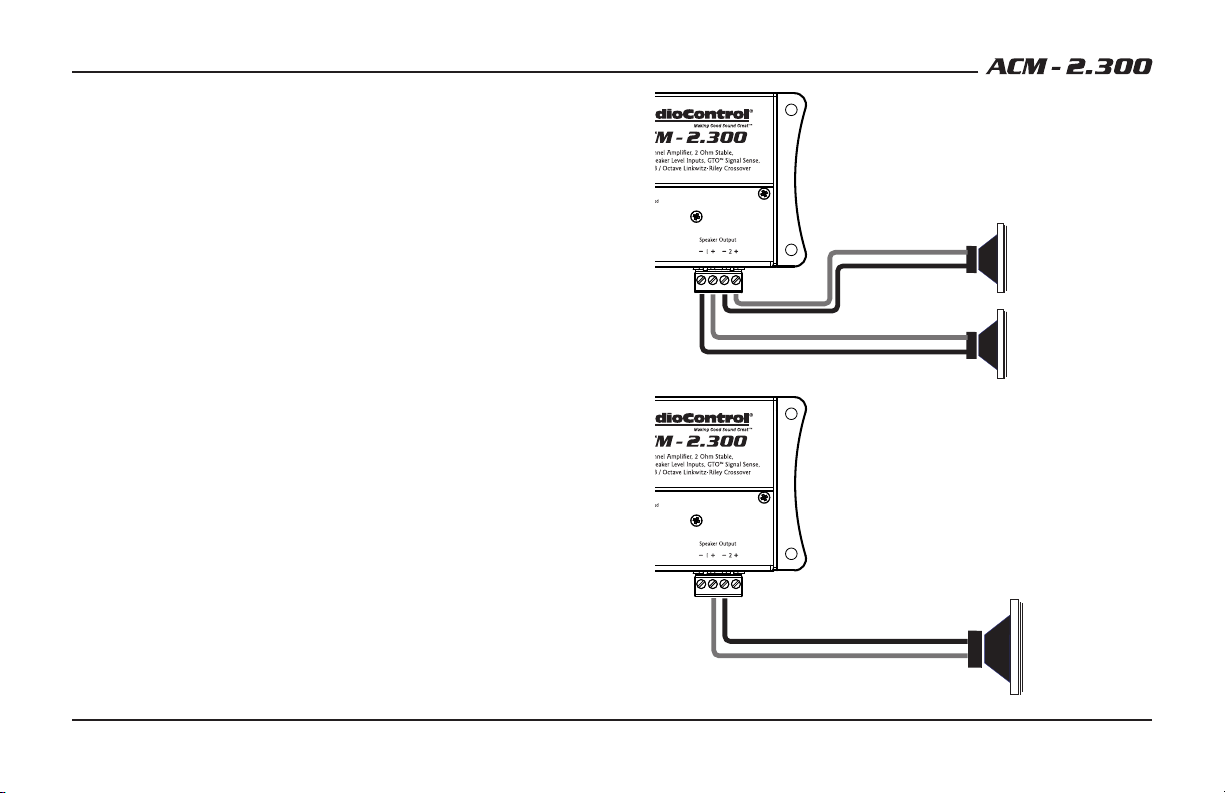
In Stereo operation, connect one loudspeaker to each channel as
shown. The minimum impedance is 2 Ohms per channel.
In Bridged Mono operation, connect one loudspeaker to the
inner 2 screw terminals ( Channel 1+ and Channel 2-) as shown.
The loudspeaker will receive the power from each channel, and
both channel inputs must be fed an input signal. The minimum
impedance is 4 Ohms.
Stereo Operation
2 Ohms Minimum per channel
+
+
Mono Operation
4 Ohms Minimum
+
+
5
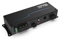
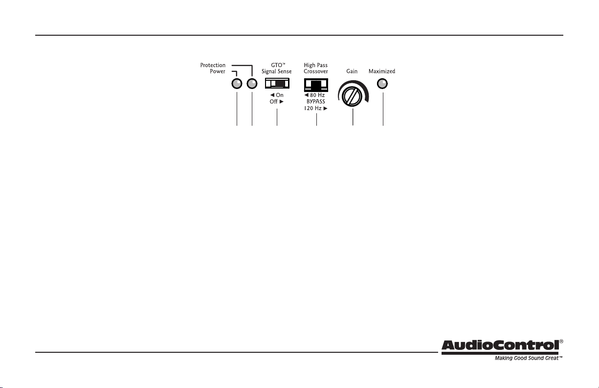
Control Panel Features
8 9 10 11
12
13
8. Power LED – If you have connected your battery power, vehicle
ground, and turn-on lead (or GTO™ signal sensing) correctly, then
this light should turn on to indicate the power is ON.
9. Protection LED – The ACM-2.300 amplier has built in diagnostic
codes to tell you exactly what is going wrong should the amplier
detect a problem. If the protection LED should come on, read the
ashing codes quickly before turning o the system and investi-
gating. (See the specs page for a list of diagnostic codes.)
10. GTO™ Signal Sense – In the ON position, the ACM-2.300 amplier
will turn on gracefully when it detects an incoming audio signal,
and it will turn o after a period of time when the audio signal
fades away to silence. In some situations, factory installed audio
systems may turn on or “wake up” due to convenience features
like door chimes, alarms, and cell phone signals that trigger the
source unit in the vehicle to come on. To prevent these from
turning your audio system on unexpectedly, you can bypass the
GTO™ circuit by moving the switch to the OFF position and use
a switched 12-volt signal connected to the Remote In terminal
instead.
11. High Pass Crossover Frequency – Since component speakers
(like woofers) are designed to reproduce certain frequency ranges,
a crossover allows you to match the speaker to the appropriate
frequency range. Most manufactures list a recommended cross-
over frequency as part of the speaker specications. Choosing
the correct crossover point will provide increased speaker
reliability and optimum sound quality. The ACM-2.300 amplier
has selectable 12 dB/Octave Linkwitz-Riley crossover points at
80 Hz, 120 Hz, and a “bypass” option. The amplier receives the
frequency range above the crossover point. Select the crossover
frequency on the ACM-2.300 amplier to best match the value
specied by your loudspeaker’s manufacturer. If you do not know
this value, select the position that suits your system best.

6
Quick Start Guide
12. Gain Control – This control allows you to adjust the overall vol-
ume output level, with counterclockwise decreasing the volume,
and clockwise increasing. The setting procedure is given on the
next page, and involves nerves of steel, a steady hand, grit, deter-
mination, and the thought that you are making the world a better
place.
13. Gain Maximized LED – This LED indicates when the ACM-2.300
amplier gain has been maximized for optimum performance.

7
Quick Start
Here are a few general steps to get your ACM-2.300 amplier up and
running:
1. Undo the +12V and Ground connections to the car battery
before making any connections to the amplier.
2. Pick a mounting location that will provide access to the controls
and connections, provide plenty of good ventilation, and also
protect the amplier from heat, moisture, and dirt.
3. The ACM-2.300 amplier needs to be securely mounted using
the four mounting holes located in each corner.
4. Before drilling any holes, take every precaution to prevent
any damage to fuel lines, power and other electrical wir-
ing, hydraulic brake lines, and other systems, that might compro-
mise vehicle safety.
5. When making connections, designate red RCA plugs as right,
and designate white, black, or grey plugs as left. This is a good
idea for consistency.
6. Use quality interconnect cables.
7. Connect the +12V input terminal of the unit to the +12V termi-
nal of the vehicle battery, using 8 to 4 AWG.
8. Connect the Ground terminal of the unit to the chassis of the
vehicle, using the same wire gauge as the +12V power wire.
9. Connect the remote power terminal of the unit to the remote
turn-on switch of your source unit. Alternatively, you can skip
this connection and use the GTO™ Signal sensing.
10. Connect your audio inputs to the unit – either speaker-level or
line-level RCA… not both.
11. Connect your loudspeakers (minimum impedance of 2 Ohms
stereo, or 4 Ohms bridged mono).
12. When all connections are made, reconnect the vehicle battery.
13. Adjust your gain setting to maximise your signal level.
14. Set the ACM-2.300 crossover to the frequency recommended by
the loudspeaker manufacturer.
15. Enjoy the drive!
8
Quick Start Guide
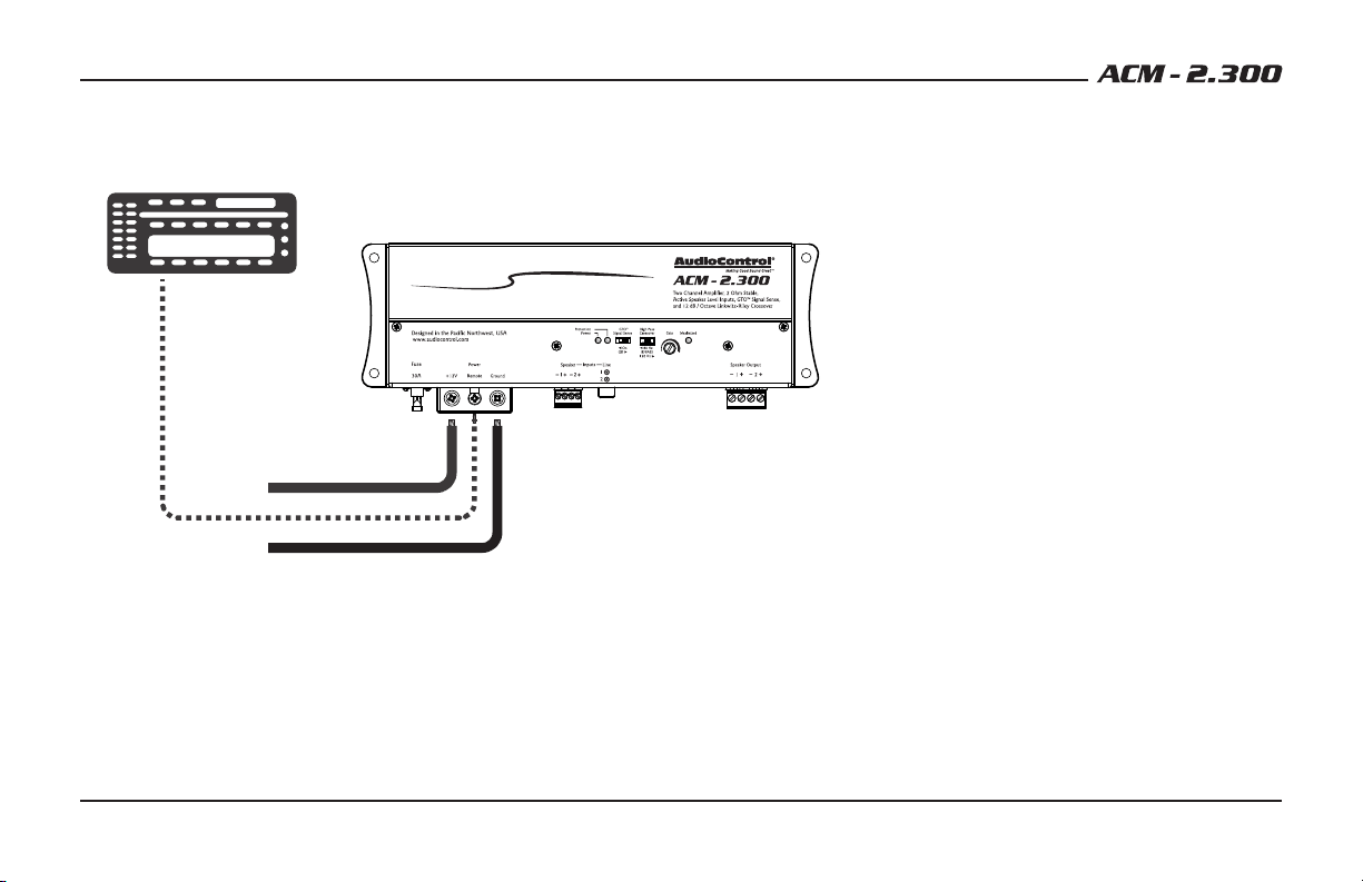
Power Connections
Ground
Head Unit
Remote Amplifier
+12V Trigger
+12V
In this example, the head unit has a +12V trigger
output that is connected to the ACM-2.300 remote
input terminal. When the head unit is turned on, it
will turn on the ACM-2.300 amplier.
Alternatively, the GTO™ signal sense feature can
be used to gently turn on the ACM-2.300 amplier
when an audio input signal is detected. (The con-
nection to the ACM-2.300 remote input terminal is
not required when using the GTO™ signal sense.)
9
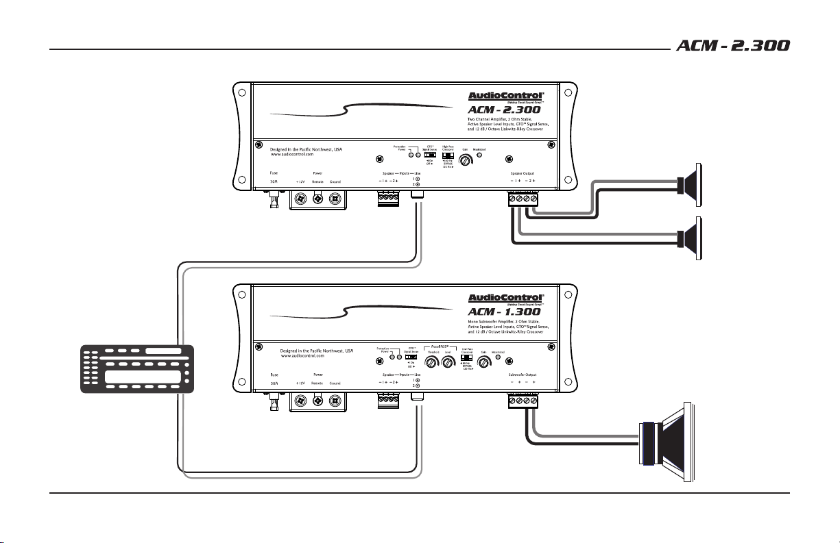
System #1: Using Speaker-Level Inputs
Factory
Radio
Speaker-level
outputs
Speaker-level
outputs
+
+
+
+
Subwoofer
Speaker-level output
80 Hz and above
Speaker-level output
80 Hz and below
ACM-1.300
Mono Subwoofer Amplifier
ACM-2.300
+
+
10
Quick Start Guide
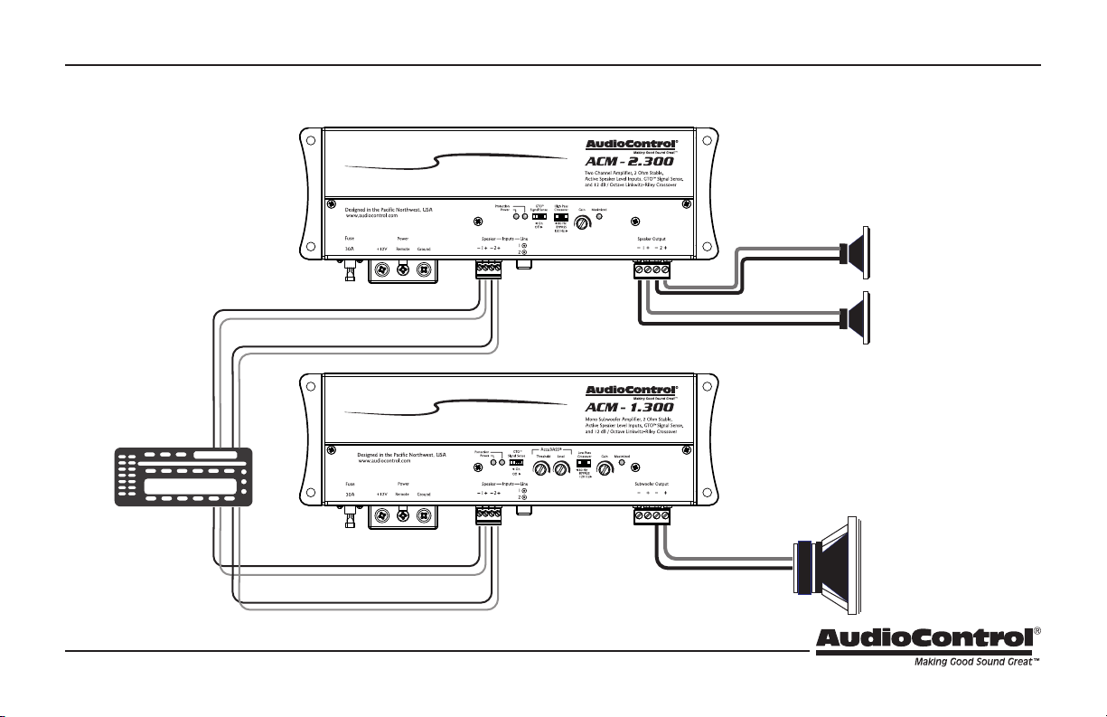
System #2: Using Line-Level Inputs
Aftermarket
Head Unit
Line-level
outputs
Line-level
outputs
+
+
L/R
L/R
Subwoofer
Speaker-level output
80 Hz and above
Speaker-level output
80 Hz and below
ACM-1.300
Mono Subwoofer Amplifier
ACM-2.300
+
+
11
Cover Plate Removal
The cover plate must be removed to gain access to
the controls, and then put back on again to protect
the controls from dust bunnies.
Removal Procedure
1. Locate the top four screws that hold the cover
plate in place.
2. Use a philips screwdriver to remove the four
screws.
3. Keep the cover plate and screws in a safe and
handy place, until you have nished adjusting
the controls to your immense satisfaction.
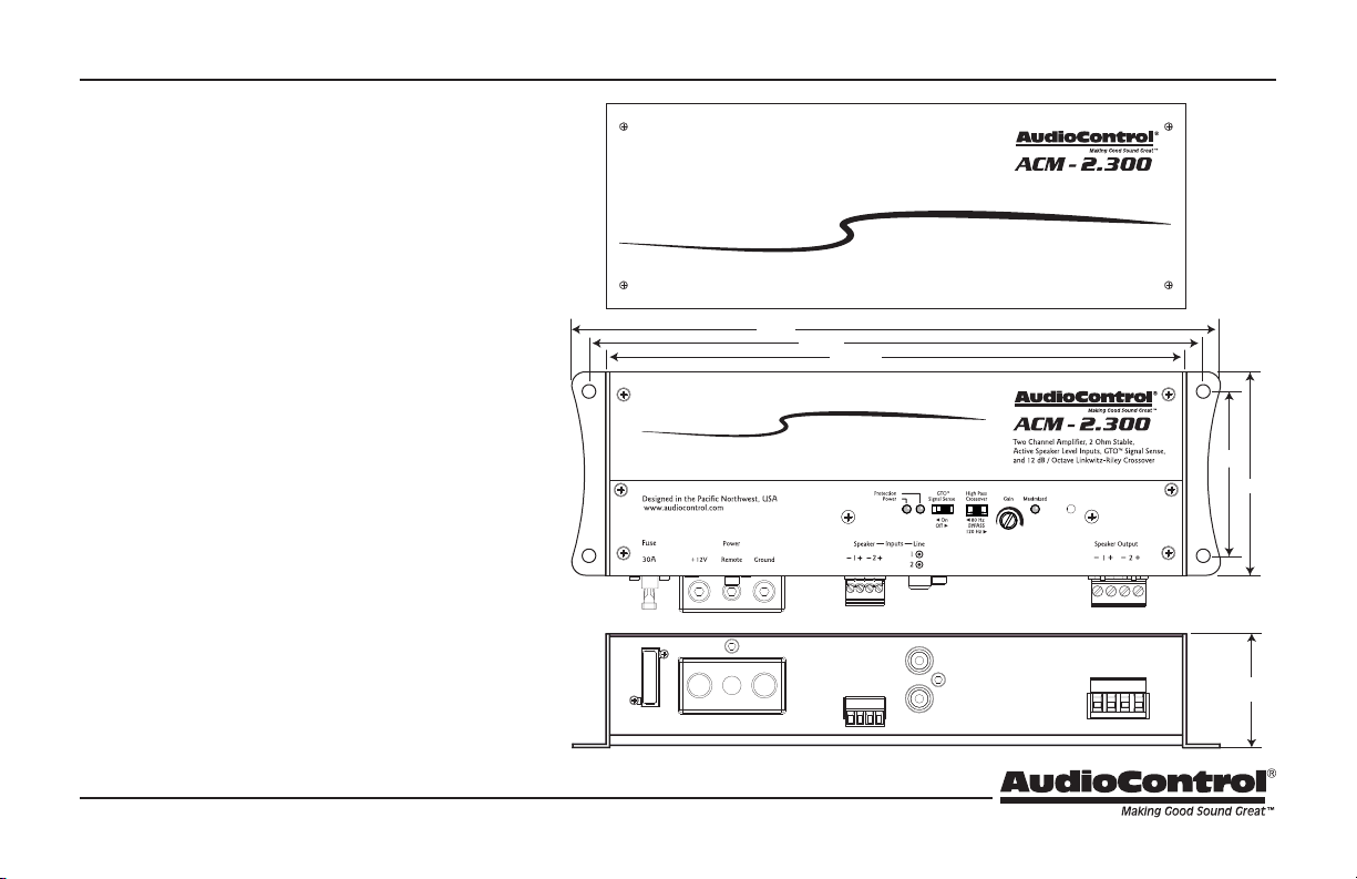
8.300”
8.910”
9.410”
2.97”
2.38”
1.75”
Quick Start Guide PN 914-018-0 Rev C
Specications
All specications are measured at 14.4 VDC (standard automotive voltage). As technology advances, AudioControl reserves the right to continuously
change our specications, like our Pacic Northwest weather, although we are working on changing that as well.
The ACM-2.300 Amplier
Power Output (RMS) ...........................2x75 Watts @ 4 Ohms
. . . . . . . . . . . . . . . . . . . . . . . . . . . . . . . . . . . . . . . . . . . . . . .2x150 Watts @ 2 Ohms
. . . . . . . . . . . . . . . . . . . . . . . . . . . . . . . . . . . . . . 1x300 Watts @ 4 Ohms Bridged
Frequency Response . . . . . . . . . . . . . . . . . . . . . . . . . . . . . . . . . . 10 Hz - 30 kHz
Total Harmonic Distortion + N . . . . . . . . . . . . . . . . . . . . . . . . . . . . . . . < 0.01%
S/N Ratio ........................... 102 dBa, Ref 50 Watts @ 4 Ohms
Power / Ground Wire Gauge ...................Between 8 and 4 AWG
Fuse Rating .............................................1 X 30 Amps
Crossover. . . . . . . . . .12dB/Octave Linkwitz-Riley, 80 Hz, 120 Hz, Bypass
Speaker-Level Inputs . . . . . . . . . . . . . . . . . . . . . . . . . . . . 2x, 40V (400W) max
Line-Level Inputs. . . . . . . . . . . . . . . . . . . . . . . . . . .2x, balanced RCA, 8V max
Weight .......................................................2.1 lbs
Dimensions ...............................9.41" W X 2.97" D X 1.75" H
©2018 AudioControl. All rights reserved.
Warranty
For details of the limited warranty for your ACM-2.300, please visit the follow-
ing page on our website: http://www.audiocontrol.com/warranty
Please keep your receipt in a safe place.
AudioControl
22410 70th Avenue West, Mountlake Terrace, WA 98043 USA,
Phone 425-775-8461, FAX 425-778-3166
e-mail: sound.great@audiocontrol.com
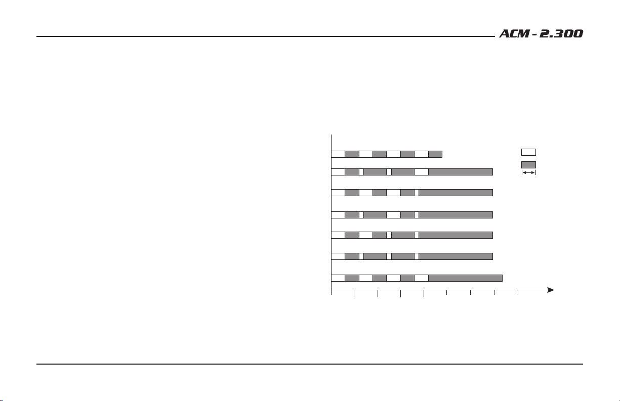
Protection Codes
The various codes ashed by the Protection LED will help you diagnose any
problems with your system.
Turn On Delay
KEY
LED ON
LED OFF
300 mS
Short Protec�on
DC Output Protec�on
Transformer Overtemp
Heatsink Overtemp
Overvoltage
Undervoltage
0 0.5 1.0 1.5 2.0 2.5
Time sec
3.0 3.5 4.0