LINSPT301228
LINSPT361228
Installation Instructions
Use and Care Information
Instructions d'installation
Utilisez et d'entretien
Instrucciones de instalación
Información de uso y cuidado
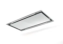
SELF SUPPORTING LINER

2
CONTENTS
Section Page
Important Safety Instructions
3
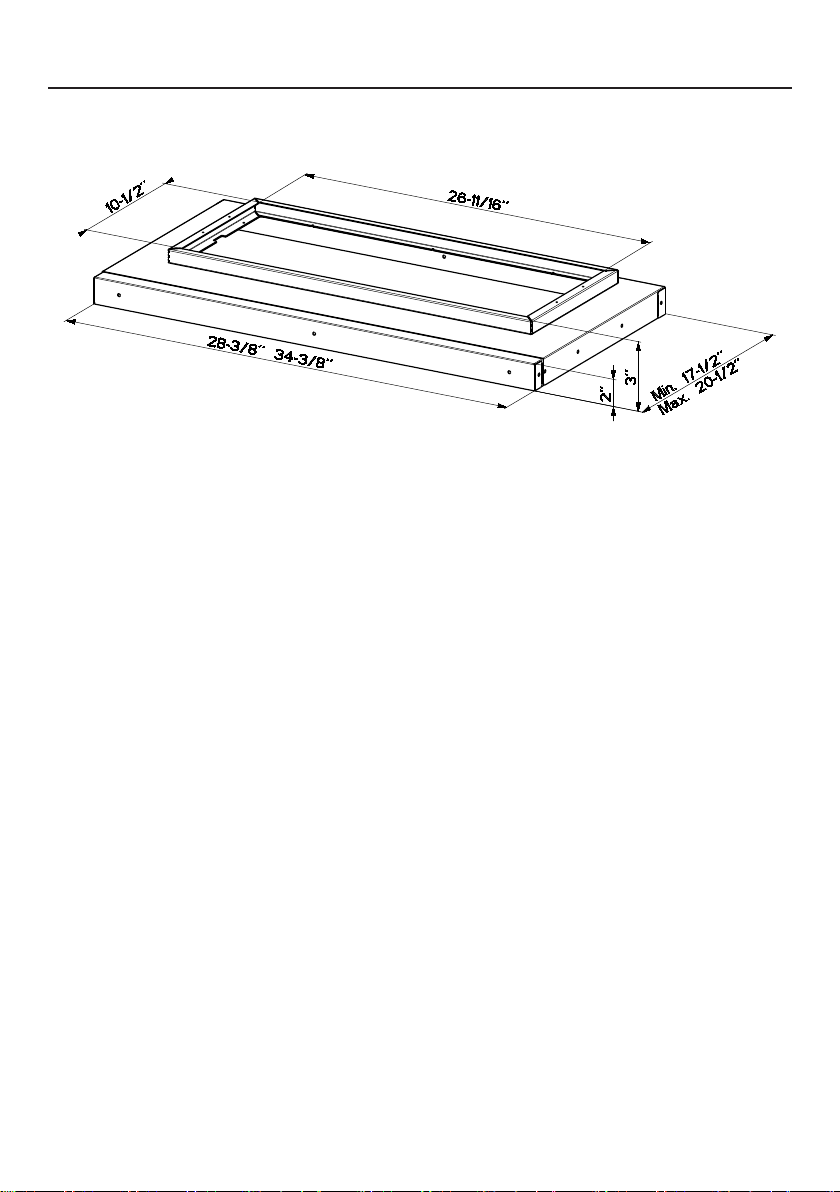
Liner Dimensions
4
Parts
4
Tools Needed
5
Preparing For Installing The Liner
6
Preparing The Cabinet Floor
7
Installing The Liner
8
Attaching The Front Trim
9
Installing The Range Hood
10

3
IMPORTANT SAFETY INSTRUCTIONS
READ AND SAVE THESE INSTRUCTIONS BEFORE YOU
START INSTALLING
Refer to Faber U&C Guides for Installation Instructions for your range hood
model.
Pre-Planning Your Installation - Important: The recommended height
to install this hood off the cooktop is a minimum of 24" over electric
cooking surfaces and a maximum of 30” over gas surfaces for maximum
effectiveness. Also consult the cooktop manufacturer’s recommendation.
4
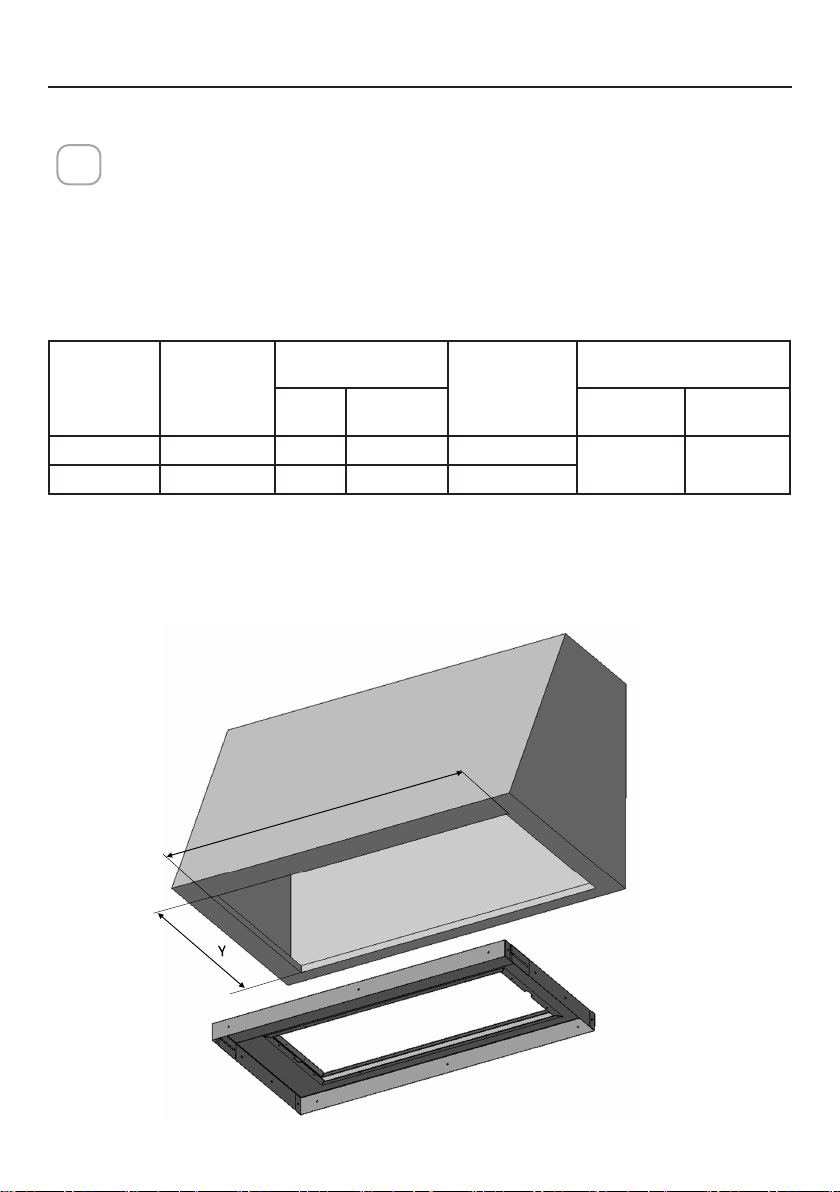
LINER DIMENSIONS
30" - 36"
DRAFT 29-OCT-2020 22:36
5
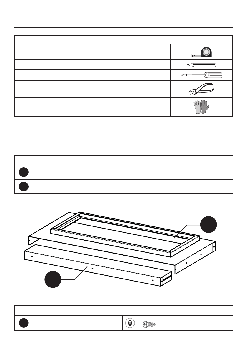
TOOLS NEEDED
TOOL
Tape Measure
Pencil
Phillips Screwdriver
Metal sheers
Work gloves
PARTS
REF. PART
QTY
A
Bottom lip of the metal liner 1
B
Front trim of the metal liner 1
REF
PART
G
Pozi Screws (1/8" x 5/8")
16
PARTS INCLUDED
A
B
6
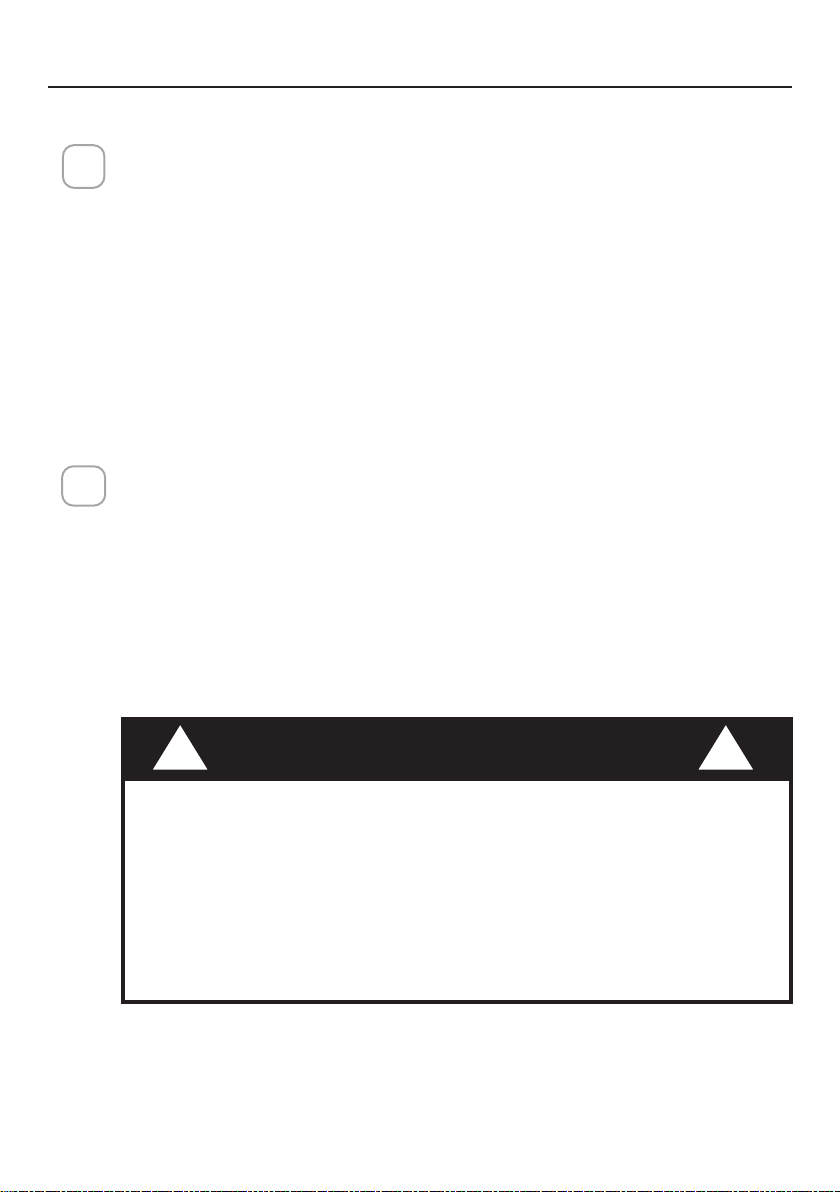
PREPARING FOR INSTALLING THE LINER
1
INSPECT THE RANGE HOOD AND THE LINER:
Fully inspect the range hood and the liner for damage before installation.
If there is damage please document and contact your retailer.
IF DAMAGED BY THE CUSTOMER, REPAIR OR REPLACEMENT IS THE
RESPONSIBILITY OF THE CUSTOMER.
IF THE UNIT IS DAMAGED BY INSTALLATION (OTHER THAN THE
CUSTOMER) REPAIR OR REPLACEMENT IS ARRANGED BETWEEN THE
CUSTOMER AND THE INSTALLER.
REMOVE THE FLOOR OF THE CABINET:
Remove the oor of the cabinet.
2.a
Make sure the surface you are securing your range hood to is capable of
holding the weight of the range hood. Review your hood's specication
to nd the exact weight of the range hood.
At a minimum your surface should be able to support 40lbs.
Failure to do so may cause personal injury or damage to the
cooking surface or counter. Wood blocking may need to be added to
the cabinet base.
WARNING
!
!
7
PREPARING THE CABINET FLOOR
Liner
Model
Wood Hood
Exterior
Width
LINER
Interior cabi-
net / Cut out
Width (x)
Interior cabinet depth /
Cut out (y)
Width Depth
Without
back panel
With back
panel *
LINSPT301228 30 inches 28 3/8'' 17 1/2'' - 20 1/2'' 28 1/2''
17 1/2'' - 20 1/2'' 17 1/8'' - 20 1/8''
LINSPT361228 36 inches 34 3/8'' 17 1/2'' - 20 1/2'' 34 1/2''
CUT OUT THE CABINET FLOOR:
In some applications, a cut-out may be needed on the cabinet floor. Use
figure below to determine the cut-out dimensions for your specific hood
application.
For less than 3/4" side walls additional trim may need to be added.
2.b
X
* Assumes back panel cabinet thickness of 3/8 "
8
3
4
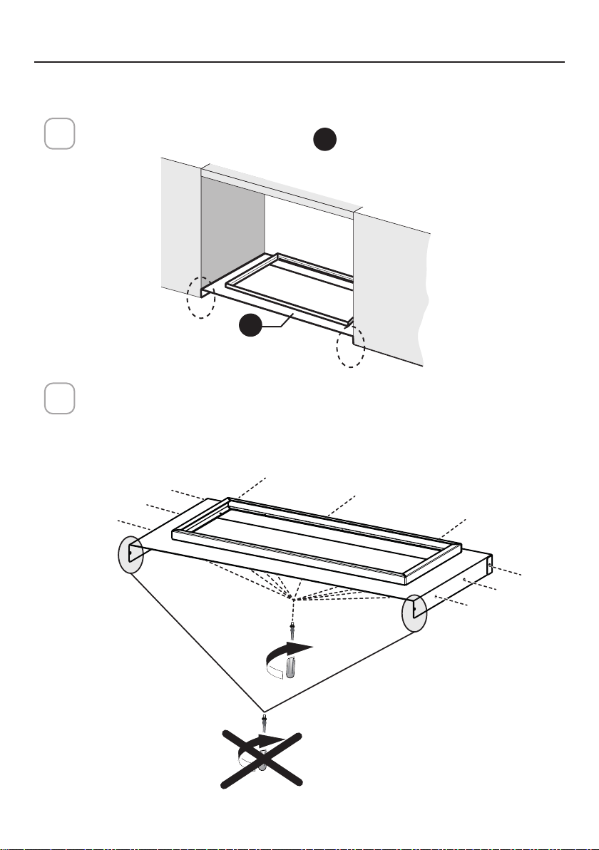
ALIGN THE LINER WITH THE CABINET FLOOR:
Align the bottom lip of the rear liner
A
with the bottom lip of the cabinet.
ATTACHING THE LINER:
Attach the back of the liner with 9 screws. 3 screws along the back, 3 on
each side.
Do not attach the screws on each side near the front trim.
These need to remain available to adjust the front part of the liner.
INSTALLING THE LINER
9x
A
9
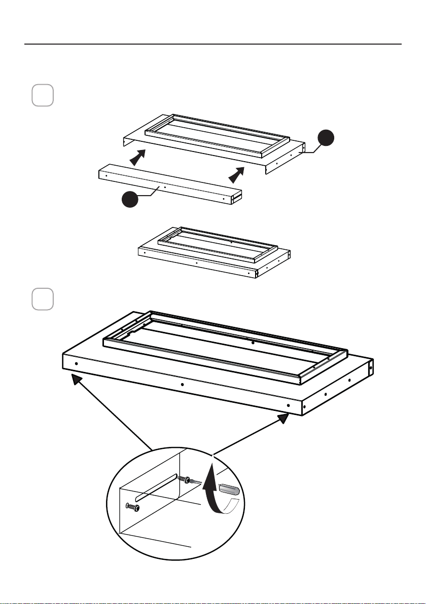
ATTACHING THE FRONT TRIM
Align the front trim to the installed portion of the liner. Use the guide
hole to locate the correct depth for the application.
Attach the front trim with 2 screws on each side of the trim.
5
6
A
B
10
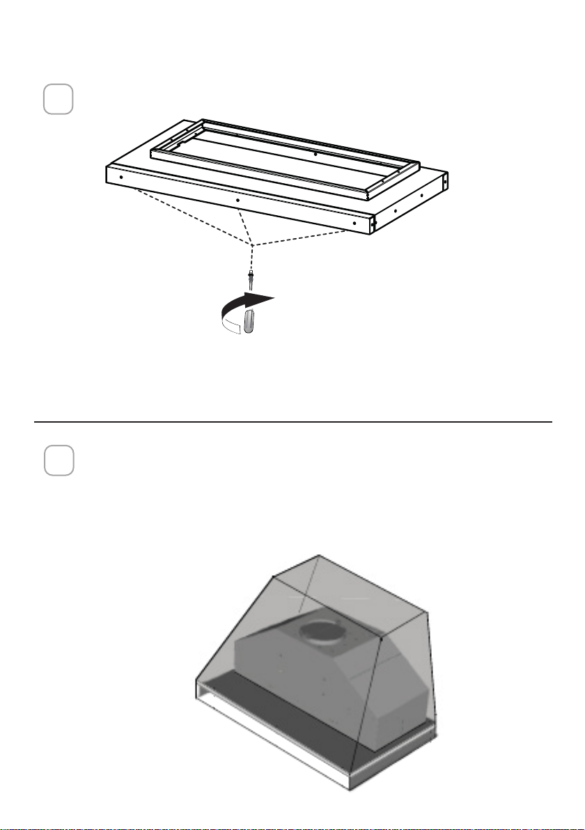
Follow the Installation Instructions for your range hood to install the range
hood to the liner.
NOTE: Inca Lux and Inca In-Light models will not need additional saftey
screws to secure the hood to the liner. For all inca model refer to the hood
installation manuals to finalize installation.
8
INSTALLING THE RANGE HOOD
Attach the front trim with 3 screws.
7
3x

11

12
TABLE DES MATIÈRES
Importantes consignes de sécurité
38
Dimensions de la hotte
42
Hauteur requise pour l’installation
43
Pièces
44
Outils requis
46
Méthode de ventilation
47
Préparation du montage de la hotte
49
Installation du support mural
54
Choisir la méthode de ventilation
55
Installation de la ventilation: option1 - canalisation vers l’arrière
56
Installation de la ventilation: option2 - ventilation vers le haut
60
Installation de la ventilation: option3 - avec recyclage sans canalisation
62
Installation du panneau
65
Branchement de alimentation domestique
66
Branchement électrique de la hotte
67
Utilisation des commandes
68
Télécommande (en option)
69
Nettoyage de l’acier inoxydable
69
Entretien des ltres
70
Remplacement des ampoules
71
Garantie
72

13
IMPORTANTES CONSIGNES DE SÉCURITÉ
VEUILLEZ LIRE ET CONSERVER LA PRÉSENTE NOTICE AVANT DE
COMMENCER L'INSTALLATION

14
CONTENIDO
Instrucciones de seguridad importantes
74
Dimensiones de la campana extractora
78
Requisitos de altura de instalación
79
Piezas
80
Herramientas necesarias
82
Método de ventilación
83
Preparación para montar la campana extractora
85
Instalación del soporte de pared
90
Elección del método de ventilación
91
Conexión de la ventilación: opción 1 - conducto trasero
92
Conexión de la ventilación: opción 2 - ventilación superior
96
Conexión de la ventilación: opción 3 - recirculación sin conducto
98
Instalación del panel de confort
101
Conexión de la alimentación de la casa
102
Conexiones eléctricas de la campana
103
Operación de los controles
104
Control remoto (opcional)
105
Limpieza del acero inoxidable
105
Cuidado de los ltros
106
Reemplazo de bombillas
107
Garantía
108

15
INSTRUCCIONES DE SEGURIDAD IMPORTANTES
LEA Y GUARDE ESTAS INSTRUCCIONES ANTES DE COMENZAR A
INSTALAR

991.0603.636_01 - 200220
D00005944_00