Loading ...
Loading ...
Loading ...
INSTALLATION
IAWARNING If your system can develop more than
Hazardous 100 PSI pressure, install a Sears No.
pressure 27220 relieve valve in system to pre-
vent possibility of tank blow-up.
NOTICE: All Captive Air® Tanks except Model 390.291352
are designed to operate in the vertical position.
The tank is shipped from the factory with a pre-charge of
air. This system DOES NOT require the use of any outside
air charging devices such as air volume controls on jet
pumps, or bleeder orifices on submersible pumps.
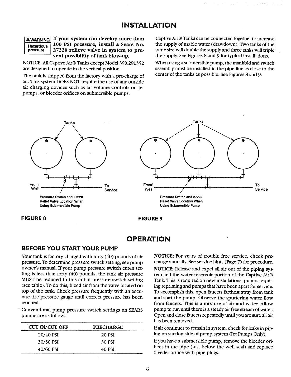
Captive Air® Tanks can be connected together to increase
the supply of usable water (drawdown). Two tanks of the
same size will double the supply and three tanks will triple
the supply. See Figures 8 and 9 for typical installations.
When using a submersible pump, the manifold and switch
assembly must be installed in the pipe line as close to the
center of the tanks as possible. See Figures 8 and 9.
Tanks
From To Froml
Well Service Well '
Pressure Switch and 27220
Relief Valve Location When
Using Submersible Pump
Tanks
I I I I I I
/
Pressure Switch end 27220
Relief Valve Location When
Using Submersible Pump
To
Service
FIGURE 8
FIGURE 9
OPERATION
BEFORE YOU START YOUR PUHP
Your tank is factory charged with forty (40) pounds of air
pressure. To determine pressure switch setting, see pump
owner's manual. If your pump pressure switch cut-in set-
ting is less than forty (40) pounds, the tank air pressure
MUST be reduced to this cut-in pressure switch setting
(see table). To do this, bleed air from the valve located on
top of the tank. Check pressure frequently with an accu-
rate tire pressure gauge until correct pressure has been
reached.
, Conventional pump pressure switch settings on SEARS
pumps are as follows:
CUT IN/CUT OFF PRECHARGE
20/40 PSI 20 PSI
30/50 PSI 30 PSI
40/60 PSI 40 PSI
NOTICE: For years of trouble free service, check pre-
charge annually. See service hints (Page 7) for procedure.
NOTICE: Release and expel all air out of the piping sys-
tem and the water reservoir portion of the Captive Air®
Tank. This is required on new installations, pumps requir-
ing repriming and pumps that have been apart for service.
To accomplish this, open faucets farthest away from tank
and start the pump. Observe the sputtering water flow
from faucets. This is a mixture of air and water. Allow
pump to run until there is a steady air free stream of water.
Open and close faucets repeatedly until you are sure all air
has been removed.
If air continues to remain in system, check for leaks in pip-
ing on suction side of pump system (Jet Pumps Only).
If you have a submersible pump, remove the bleeder 015-
rices in the pipe (just below the well seal) and replace
bleeder orifice with pipe plugs.
Loading ...
Loading ...
Loading ...