Loading ...
Loading ...
Loading ...
Freehand
Using the tool without holding the workpiece firmly
against the fence and table. This can let the workpiece
twist and kick back and must never be attempted.
Gum
A sticky, sap based residue from wood products.
Hold.Down/Push-Blocks
They are required for your own safety. They are used to
hold your wo_pieces against the table and fence when
planing, rabbeting or jointing.
infeed Table
The section of the jointer bed upon which the workpiece
is placed before being pushed into the cutter head.
Infeed table height is adjustable which allows the opera-
tor to select the depth of cut.
Jointing
The removal of wood along the edge of a board so as to
make that edge straight, smooth and square to the board
face which is against the fence.
Kickback
An uncontrolled grabbing and throwing of the workpiece
back toward the operator by the rotating cutter head.
Leading End
The end of the workpiece which is pushed intothe cutter
head first.
Ouffeed Table
The section of a jointer bed which supports the workpiece
after itpasses over the cutter head.
Planing
Removing wood from the widest surface or face of a
board so as to make itflat and smooth.
Rabbet
A notch cut into the edge ofworkpiece.
Resin
A sticky, sap based substance that has hardened.
Revolutions Per Minute (RPM)
The number of turns completed by a spinning object in
one minute.
Throw-Back
Throwing of pieces in a manner similar to a kickback.
Trailing End
The workpiece end last cut by the knives.
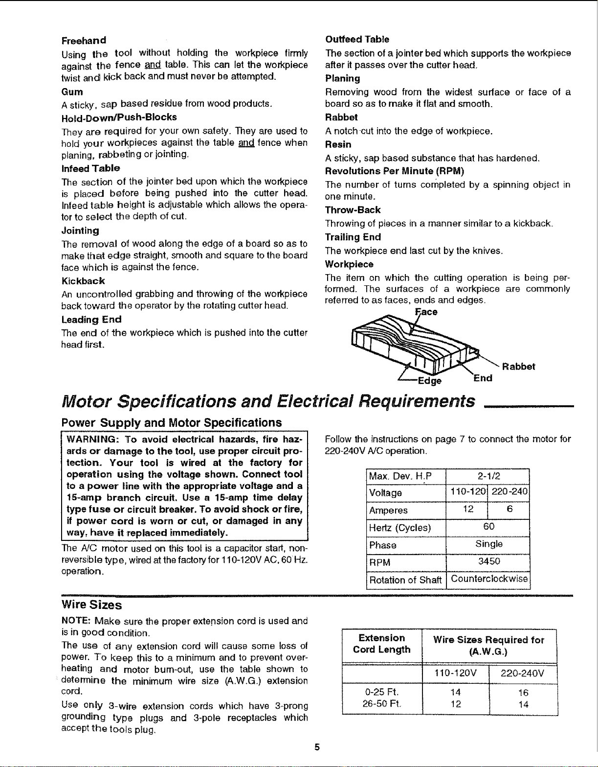
Workpiece
The item on which the cutting operation is being per-
formed. The surfaces of a workpiece are commonly
referred to as faces, ends and edges.
'Edge End
Motor Specifications and Electrical Requirements
Power Supply and Motor Specifications
WARNING: To avoid electrical hazards, fire haz-
ards or damage to the tool, use proper circuit pro-
tection. Your tool is wired at the factory for
operation using the voltage shown. Connect tool
to a power line with the appropriate voltage and a
15-amp branch circuit. Use a 15-amp time delay
type fuse or circuit breaker. To avoid shock or fire,
if power cord is worn or cut, or damaged in any
way, have it replaced immediately.
The A!© motor used on this tool is a capacitor start, non-
reversible typ e, wired at the factory for 110-120V AC, 60 Hz.
operation.
ii !nllllH Ul
Wire Sizes
Follow the instructions on page 7 to connect the motor for
220-240V A/C operation.
Max. Dev, H.P
Voltage
Amperes
Hertz (Cycles)
Phase
RPM
2-1/2
110"120 220-24-0
12 6
60
Single
3450
Rotation of Shaft Counterclockwise
NOTE: Make sure the proper extepsion cord is used and
is in good condition.
The use ot any extension cord will cause some toss o!
power. To keep this to a minimum and to prevent over-
heating and motor bum-out, use the tabte shown to
determine the minimum wire size (A.W.G.) extension
cord.
Use or_ty 3-wire extension cords which have 3_prong
grounding type plugs and 3-pole receptacles which
accept the tools ptug.
q
Extension
Wire Sizes Required for |
Cord Length (A.W.G.) /
........... , .......,.......... ,.... !
110-120V 220_240V
0-25 Ft, 14 16
26-50 Ft. 12 14
Loading ...
Loading ...
Loading ...