
Loading ...
Loading ...
Loading ...
12
ENGLISH
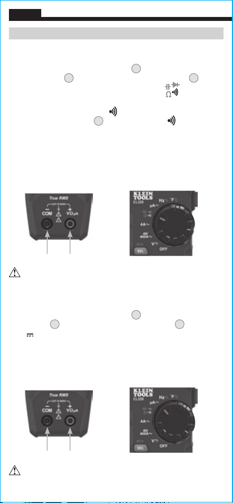
CONTINUITY
1. Insert RED test lead into VΩµA jack
5
, and BLACK test lead
into COM jack
4
, and rotate function selector switch
2
to the
Continuity/Resistance/Capacitance/Diode-Test
setting.
NOTE: The meter defaults to Continuity testing in this mode. Ensure
that the Continuity Testing icon is visible on the display. If not,
press the "SELECT" button
12
repeatedly until the icon is shown.
2. Remove power from circuit.
3. Test for continuity by connecting conductor or circuit with test
leads. If resistance is measured less than 10Ω, an audible signal
will sound and display will show a resistance value indicating
continuity. If circuit is open display will show "OL".
µA DC CURENT (LESS THAN 200 µA)
1. Insert RED test lead into VΩµA jack
5
, and BLACK test lead into
COM jack
4
, and rotate function selector switch
2
to the
µA
setting.
2. Remove power from circuit and open circuit at measurement point.
3. Connect test leads in series with the circuit.
4. Apply power to the circuit to take the measurement.
DO NOT attempt to measure continuity on a live circuit.
OPERATING INSTRUCTIONS
DO NOT attempt to measure more than 200 µA.
Red leadBlack lead
Red leadBlack lead
Loading ...
Loading ...
Loading ...