Loading ...
Loading ...
Loading ...
31-5000493 Rev. 4 13
2) Outside Air Damper Interface Instructions
Source a 4” diameter normally closed damper by others to regulate the supply of outdoor air. Install
damper as per manufacturers recommendations. To control the operation of the outdoor air damper with the
air handler, use this procedure to interface the two systems:
• Enable the function by setting the Duct unit SW1_6 dip switch to OFF.
• There is a 4” round (plastic) flange on the side of the air handler available for Outdoor Air inlet.
Remove the flange and center knock-out, rotate flange 180º and replace.
• Connect 4” round damper/duct to Air Handler Flange.
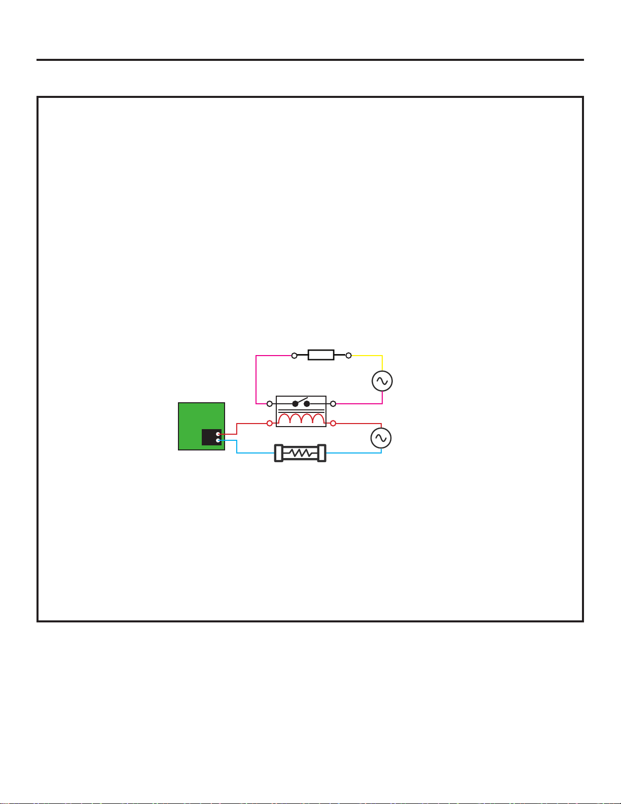
• Route the power supply to the Damper through a third party 24VAC relay dry contacts rated for the
Damper amp draw and voltage. Interupt power to the relay coil with the dry contacts on the board CN10
connector using the provided connector leads (Maximum 240VAC 3Amp). See schematic below for
reference.
NOTE: For continuous fan mode operation, SW3_1 should be set to ON and the SW1_6 should be OFF.
OUTSIDE AIR DAMPER
CN10
CIRCUIT
BOARD
RELAY
24VAC
IN-LINE FUSE 3A
DAMPER
POWER SUPPLY
DAMPER
The CN-10 contacts will OPEN under any of the following
conditions:
1. The DIP switch SW1_6 is set to ON.
2. The fan turns off.
3. The fresh air command is disabled by the I.R.
controller/wired controller.
4. The unit is disabled or turned off.
The CN-10 dry contacts will only CLOSE if all of these
conditions are met:
1. The unit has called for the fan to operate.
2. The DIP switch SW1_6 is set to OFF.
3. Fresh air command is enabled by the I.R. Controller/
Wired controller.
Optional Control Functions
Installation Instructions
Loading ...
Loading ...
Loading ...