Loading ...
Loading ...
Loading ...
31-5000493 Rev. 4 11
Step 2 - Mounting the Unit (Cont.)
I.
DIP Switch Settings
The DIP switch bank on the PCB need to be checked. Need
to make sure all switches are in the correct position including
a field-supplied external static pressure setting per the table
below.
SW3_1 Special fresh
Air (Canada
particular Area)
[1] ON Special Fresh
Air function
valid
Factory default
setting: OFF
OFF Special fresh
Air funtion
invalid
SW3_2 Reserved [2] ON Reserved Factory default
setting: OFF
OFF Reserved
SW3_3 Auxiliary
heater
[3] ON Auxiliary
heater
Function valid
Factory default
setting: OFF
OFF Auxiliary
heater
Function
invalid
SW3_4 Slim duct or
MESP DUCT
[4] ON MESP DUCT
(10 ESP level)
Factory default
setting: According
to model
OFF Slim DUCT (10
ESP level)
SW3_5
SW3_6
SW3_7
SW3_8
IDU address
for wired
controller
group
Control
application
[5] [6] [7] [8] IDU Address
OFF OFF OFF OFF 0# (main)
(Factory default
setting)
OFF OFF OFF ON 1# (subordinate)
OFF OFF ON OFF 2# (subordinate)
OFF OFF ON ON 3# (subordinate)
OFF ON OFF OFF 4# (subordinate)
OFF ON OFF ON 5# (subordinate)
OFF ON ON OFF 6# (subordinate)
OFF ON ON ON 7# (subordinate)
ON OFF OFF OFF 8# (subordinate)
ON OFF OFF ON 9# (subordinate)
ON OFF ON OFF 10# (subordinate)
ON OFF ON ON 11# (subordinate)
ON ON OFF
OFF 12# (subordinate)
ON ON OFF ON 13# (subordinate)
ON ON ON OFF 14# (subordinate)
ON ON ON ON 15# (subordinate)
SW1_1
SW1_2
SW1_3
Capacity
[1] [2] [3] Capacity
OFF OFF OFF 9000BTU/h
ON OFF OFF 12000BTU/h
OFF ON OFF 18000BTU/h
ON ON OFF 24000BTU/h
OFF OFF ON 30000BTU/h
ON OFF ON 36000BTU/h
OFF ON ON 42000BTU/h
ON ON ON 48000BTU/h
SW1_4 Room card OFF Room card invalid (factory
default)
ON Room card valid
SW1_5 Heat pump /
Cool only
OFF Heat pump (factory
default)
ON Cool only
SW1_6 Fresh air/E.A.O OFF Fresh air valid (factory
default)
ON External alarm output valid
SW1_7 Filter change
notice / IDU fan
behavior when
cooling set
temp reached
OFF No Filter change notice /
fan stop when set temp
reached (factory default)
ON Filter change notice / fan
stays on when set temp
reached
SW1_8 North America/
NON- North
America
OFF North America area (USA
& Canada) (factory default)
ON NON-North America
Installation Instructions
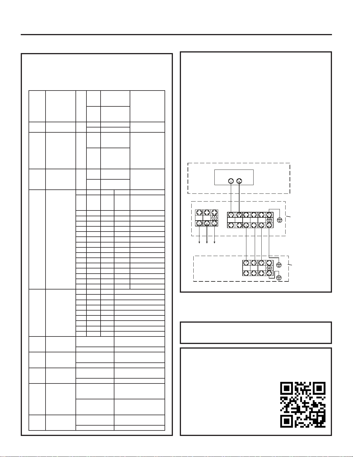
Step 3 - Electrical Connections
Step 4 - Leak Testing, Evacuation
and Wifi
Electrical Connections Indoor and Outdoor
Units
14/4 non-shielded stranded copper cable only.
Maintain 10 feet of distance from TV, radio or any
communication wiring.
NOTE: If cable connecting Indoor & Outdoor unit >
180ft (55m), the Indoor unit ground wire should be
separated from the cable.
NOTE: See the Wired Controller Operation and
Installation Manual for more information.
Refer to the outdoor section Installation
Manual for the recommended procedure.
Wifi Pairing
1. Download the “SmartHQ” app from Google Play
(Android) or the Apple app store (IOS).
After downloading the App:
2. Open the app.
3. Select “Sign In”.
4. Sign into your account or register
as a new user.
5. Select the “+” icon to add a new
device and follow the directions in
the app.
L1 L2
1 2 3
1 2 3
POWER SUPPLY
208/230V 60Hz
Outdoor unit
terminal blocks
Indoor unit
terminal block
MESP DUCT
C1C2
central controller
A
B
Loading ...
Loading ...
Loading ...