Loading ...
Loading ...
Loading ...
12 31-5000493 Rev. 4
Installation Instructions
The air handler supports the ability to (1) activate or deactivate auxiliary ducted heaters (by others) and to
(2) activate or deactivate external air dampers (by others) for drawing in outside air.
1) Auxiliary Heater Interface Instructions
Auxiliary ducted heaters should be sized to fit the supply plenum and avoid bypass air connections. Install
heater as per manufacturers recommendations. To control the operation of the auxiliary heaters with the air
handler, use this procedure to interface the two systems:
• Enable the function by setting the Duct unit SW3_3 dip switch to ON.
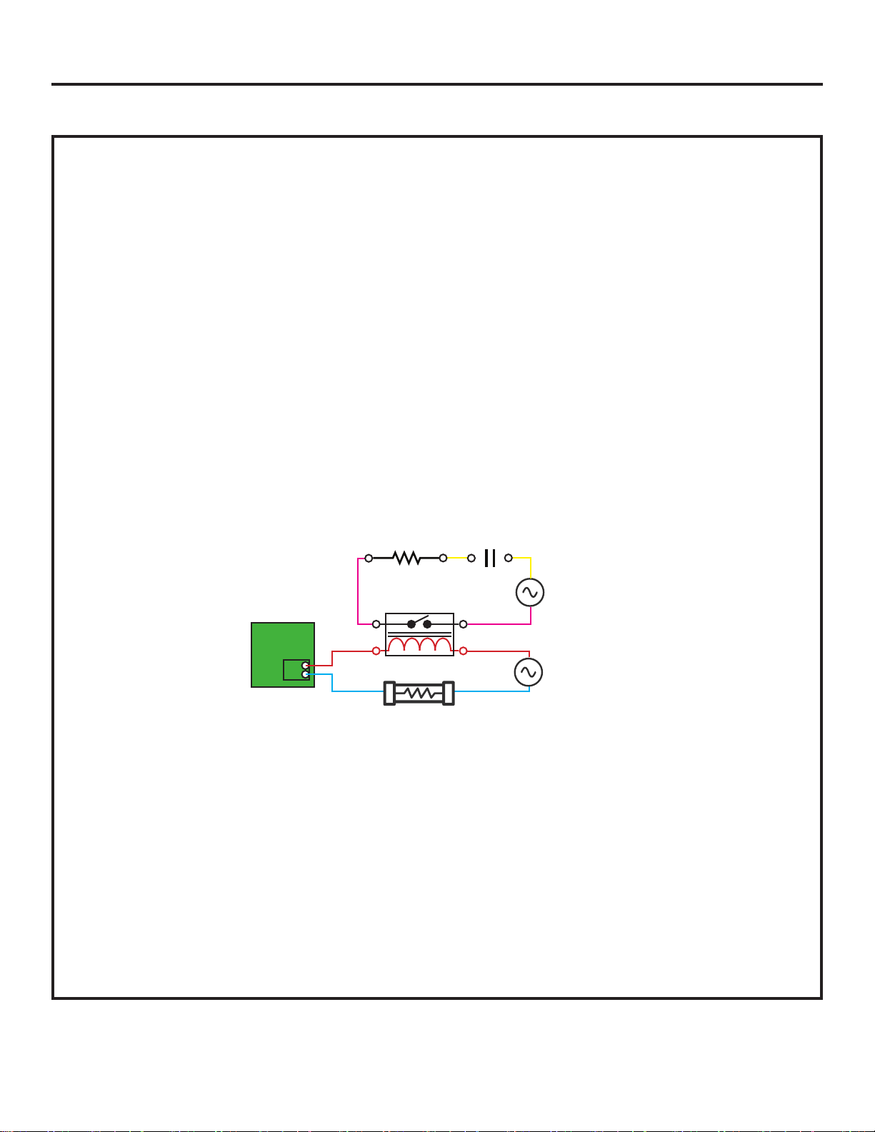
• Route the power to the auxiliary heater through a third party 24VAC relay normally-open contacts rated
for the amp draw and voltage of the heater. Interrupt power to the Relay coil with the dry contacts on the
board’s Green CN4 plug (Maximum 240VAC 3Amp). See the schematic below for reference.
WARNING: It is recommended to use the wired controller to set the Duct Static pressure and to ensure
adequate airflow for the total heat load (see page 10 section H). Failure to do this may overheat auxiliary
heaters.
NOTE: Use of a Differential Air Pressure switch for air flow proving with normally open contacts to interupt
supply power to the Auxiliary heater is recommended in the event of a fan failure.
AUX. HEATER
CN-4
CIRCUIT
BOARD
RELAY
24VAC
IN-LINE FUSE 3A
AUX. HEATER
POWER SUPPLY
HEATER
AIR PROVING
The CN-4 contacts will OPEN under any of the following
conditions:
1. Set point is achieved.
2. Temperature exceeds 26°C/78.7°F.
3. The indoor unit fan motor stops.
4. The mode is changed from Heat Mode.
5. The Indoor Coil sensor exceeds 45°C/113°F.
6. SW3_3 is set to off.
The CN-4 dry contacts will only CLOSE if all of these
conditions are met:
1. The unit has called for the fan to operate.
2. The indoor temperature is 3.6ºF/2ºC less than the
controller set point.
3. The outdoor unit has been running for 1 min or more
without reaching set point.
4. The room temperature is less than 77ºF / 25ºC.
5. The DIP switch SW3_3 is set to ON.
6. The system is running in heat mode or AUTO
heat mode.
7. The indoor unit gas pipe sensor is less than
113ºF / 45ºC.
Optional Control Functions
Loading ...
Loading ...
Loading ...