Loading ...
Loading ...
Loading ...
SERVICING - WARNING
Disconnect from electricity and gas before servicing. Check appliance is safe when you have nished.
8
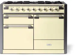
5. Removal Facia Assembly
Disconnect the appliance from the electricity Supply
Disconnect from the Gas Supply
a. Remove the (x9) Control Knobs
b. Remove the (x3) xing from the interface between
the Facia and the Hotplate
c. Remove the Hand Rail (1. To Remove the Handrail)
d. Remove the (x4) xings from the underside of the
Fascia, support the fascia during this operation.
e. There are (x4) signal lamps mounted to the rear of
the facia assembly, gently grip the end of the signal
lamp body and pull away from the red lens. The red
lens will remain on the facia panel – Repeat for the
other signal lamps.
f. Re- Assembly: Reassemble in the reverse order,
making sure all electrical connections broken are
returned to their normal operating state. Please refer
to the wiring diagram as required.
g. Check the electrical safety of the appliance by
carrying out the appropriate electrical safety
checks, earth bond and high Voltage Hi Pot tests.
6. Removal of the Gas Hotplate
Disconnect the appliance from the electricity Supply
Disconnect from the Gas Supply
a. Remove the Facia (5. Removal Facia Assembly)
b. Remove the (x5) burner caps, this gives access to the
brass Venturi.
c. Remove the (x5) brass Venturi from the centre of each
burner.
d. Remove the (x8) gas hotplate retaining screws.
e. Lift up each burner base and remove the spark (High
Tension) HT lead, take care not to lose the protective
sleeve.
f. Lift the Gas Hotplate away and position safely, you
now have access to:
• Spark Generator
• Appliance Controls
• Gas Taps
• Thermocouples – Flame Failure Device
• Appliance Wiring.
g. Re- Assembly: Reassemble in the reverse order,
making sure all electrical connections broken are
returned to their normal operating state. Please refer
to the wiring diagram as required.
h. Check the electrical safety of the appliance by
carrying out the appropriate electrical safety
checks, earth bond and high Voltage Hi Pot tests.
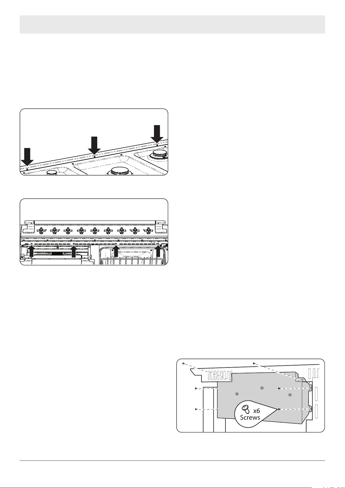
7. Removal of the Cooling Fan
Disconnect the appliance from the electricity Supply
Disconnect from the Gas Supply – Remove any
Safety Chains that may be present.
a. Access to the cooling fan assembly is from the rear of
the appliance.
• Place protective means on the floor to prevent
any damage to floor whilst moving the appliance
forward.
• Remove the (x6) securing screws from the Fan
assembly box.
Loading ...
Loading ...
Loading ...