Safety oAssembly oOperation o Adjustments oMaintenance oTroubleshooting o Parts Lists oWarranty
®
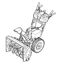
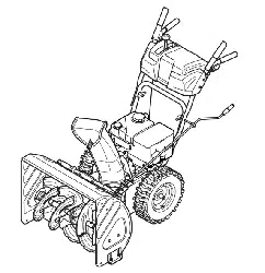
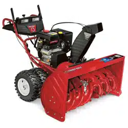
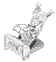
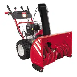
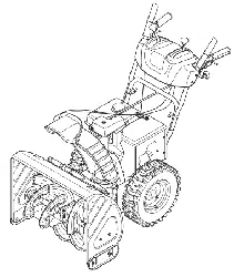
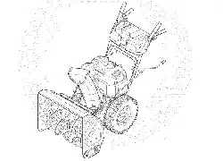
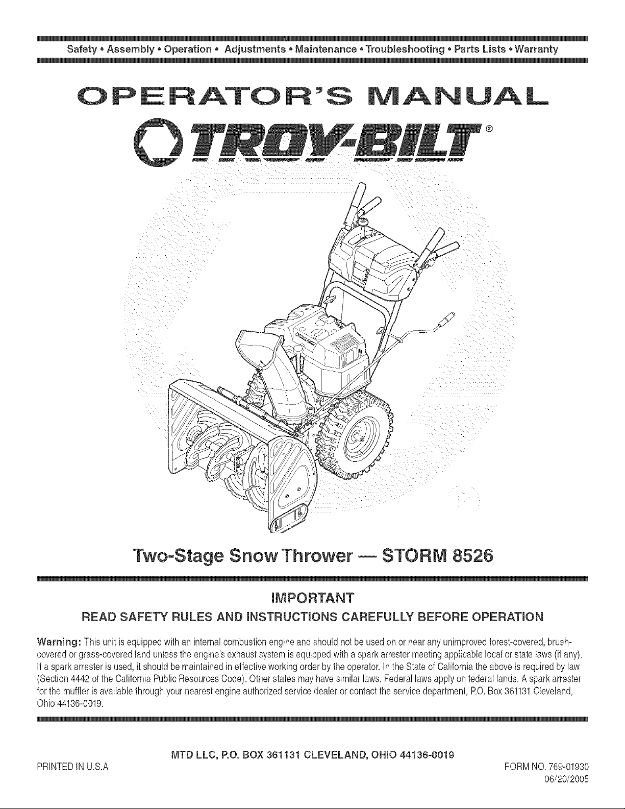
Two-Stage Snow Thrower -- STORM 8526
READ SAFETY RULES AND mNSTFIUCTmONS CAREFULLY BEFORE OPEFIATmON
Warning: This unitis equippedwithan internalcombustionengineandshouldnot beusedon or nearany unimprovedforest-covered,brush=
coveredor grass=coveredlandunlessthe engine'sexhaustsystemis equippedwitha sparkarrestermeetingapplicablelocalor state laws(if any),
If a sparkarresteris used,it shouldbemaintainedineffectiveworkingorderby the operator,Inthe Stateof Californiathe aboveis requiredbylaw
(Section4442of the CaliforniaPublicResourcesCode),Otherstatesmayhavesimilarlaws,Federallawsapplyonfederallands,A sparkarrester
for the muffleris availablethroughyournearestengineauthorizedservicedealeror contactthe servicedepartment,RO,Box361131Cleveland,
Ohio44136=0019,
PRINTEDIN U,S,A
MTD LLC, RO. BOX 361131 CLEVELAND, OHIO 44136-0019
FORMNO,769=01930
06/20/2005
This Operator's Manua_ is an important part of your new snow thrower, mtwHI help you assemble,
prepare and maintain the unit for best performance. P_ease read and understand what it says.
Table of Contents
Safety Labels ...................................................... 3
Safe Operation Practices ................................... 4
Setting Up Your Snow Thrower .......................... 6
Operating Your Snow Thrower ........................... 8
MakingAdjustments ......................................... 12
Maintaining Your Snow Thrower ...................... 14
Off°SeasonStorage ........................................... 18
TrouMe Shooting .............................................. 19
H_ustrated Parts List ......................................... 20
Warranty ............................................ Back Cover
Finding and Recording Model Number
BEFOREYOU STARTASSEMBLING
YOUR NEW EQUIPMENT,
please locate the model plate on the equipment and copy the
information to the sample model plate providedto the righL
Youcan locate the model plate by standing at the operating
position and looking down at the rear of the deck. This
information will be necessary to use the manufacturer's web
site and/or obtain assistance from the Customer Support
Department or an authorized service dealer.
0 TRD BILT° TRO¥-BmLTLc
P. O. 80X 361131
CLEVELAND, ON 44136
338-558-7228
Customer Support
P_ease do NOTreturn the unit to the retailer from which it was purchased,
without first contacting Customer Support.
if you have difficulty assembling this product or have any questions regardingthe controls,operation or maintenance of this unit,
you can seek help from the expert& Choose from the options below:
1, VisittroybHt.com for manyusefulsuggestions,Clickon Customer
Supportbuttonandyouwill get the optionsreproducedin thescreen
shotbelow,CIbk onthe appropriatebuttonandhelpis immediately
available,
3, Theengine manufacturer is responsiblefor all engine-relatedissues
withregardto performance,power-rating,specifications,warrantyand
service,Pleasereferto the enginemanufacturer'sOwner's/Operator's
Manual,packedseparatelywithyourunit,for moreinformation,
2, Phonea Customer Support Representative at 1(800)520-5520,
2
m
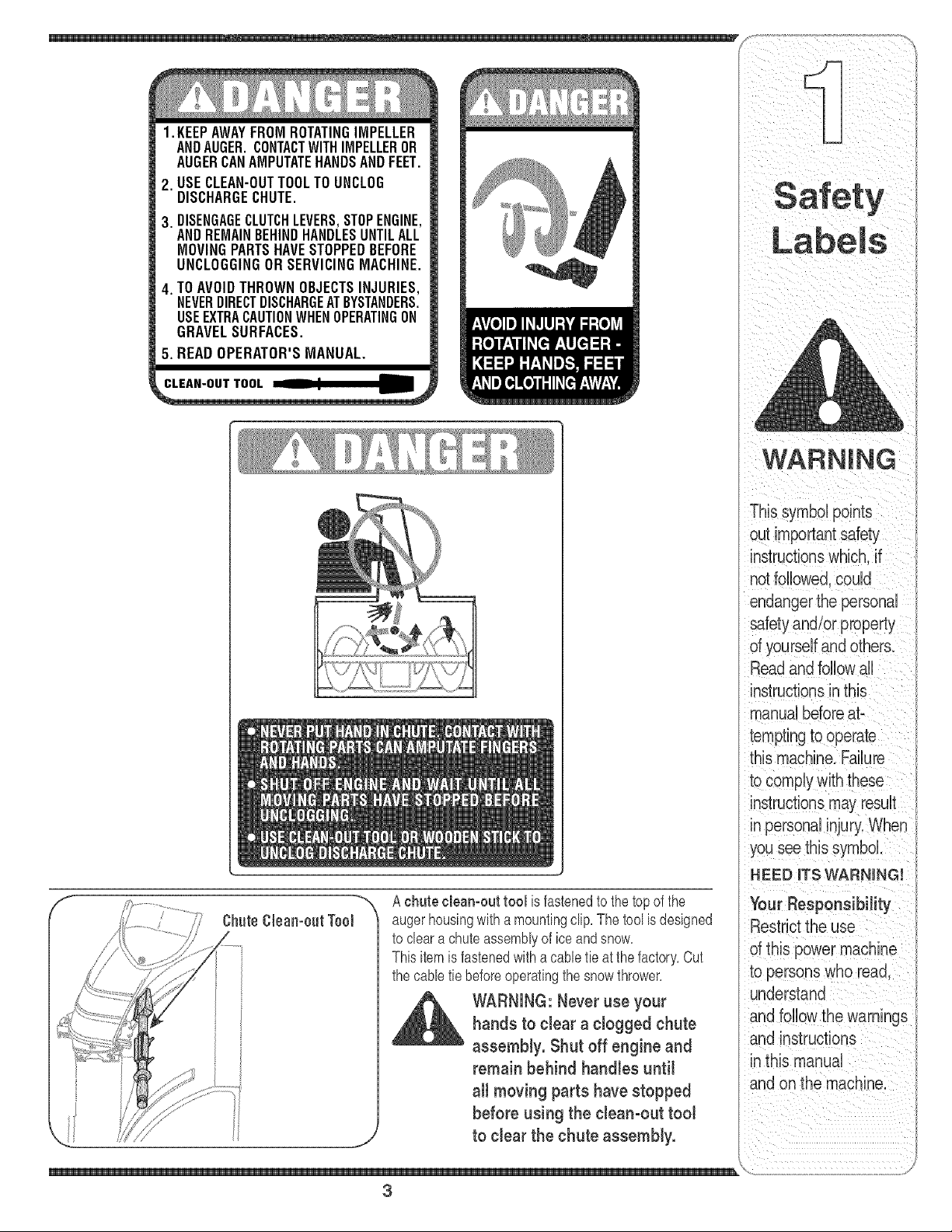
1. KEEPAWAYFROMROTATINGIMPELLER
ANDAUGER.CONTACTWITHIMPELLEROR
AUGERCANAMPUTATEHANDSANDFEET.
2. USECLEAN-OUTTOOLTO UNCLOG
DISCHARGECHUTE.
3. DISENGAGECLUTCHLEVERS,STOPENGINE,
ANDREMAINBEHINDHANDLESUNTILALL
MOVINGPARTSHAVESTOPPEDBEFORE
UNCLOGGINGORSERVICINGMACHINE.
4. TOAVOIDTHROWNOBJECTSINJURIES,
NEVERDIRECTDISCHARGEATBYSTANDERS.
USEEXTRACAUTIONWHENOPERATINGON
GRAVELSURFACES.
5. READOPERATOR'SMANUAL.
A chute cleamout tool is fastenedto the top of the
augerhousingwith a mountingclip, The tool is designed
to cleara chute assemblyof ice and snow,
This item is fastenedwith a cable tie at the factory,Cut
the cabletie beforeoperatingthe snowthrower,
WARNING:Never use your
hands to clear a clogged chute
assembly. Shut off engine and
remain behind handles until
all moving parts have stopped
before using the clean-out tool
to clear the chute assembly.
Your ResponsibiJity
Restrict the use
Of this power machine
to persons who read,
Undeistand
and fo!!ow the warn!ngs
and instructions
inthis manual
and on the roachne:
3
WARNING:EngineExhaust,someofitsconstituents,andcertainvehiclecompo_
nentscontainoremitchemicalsknownto StateofCaliforniatocausecancerand
birthdefectsorotherreproductiveharm.
DANGER:Thismachinewasbuilttobeoperatedaccordingtotherubsforsafeoperationinthis
manual.Aswithanytypeofpowerequipment,carelessnessorerroronthepartoftheoperatorcan
Sa.'_e resultinseriousinjury.Thismachineiscapableofamputatinghandsandfeetandthrowingobjects.
,, Failuretoobservethefollowingsafetyinstructionscouldresultin seriousinjuryordeath.
Operation Training Preparation
1. Read,understand,andfollowall instructionsonthe 1. Thoroughlyinspectthe areawherethe equipmentis to be
WARNING
sut importantsafety
endangerthe personal
safety and/or property
of yourself and others.
Read and follow all
manualbeforeat-
temptingto operate
this machine. Failure
in personalinjury,When
you see this symbol,
HEED iTS WARNING[
Your Responsibility
Restrictthe use
sf this powermachine
to persons who read.
understand
and follow the warnings
and instructions
in this manual
and on the machine.
machineandin themanual(s)beforeattemptingto
assembleand operate.Keepthis manualina safeplacefor
futureand regularreferenceandfor orderingreplacement
parts. 2.
2. Be familiarwith all controlsandtheir properoperation.
Knowhowto stopthe machineanddisengagethem quickly.
3. Neverallowchildrenunder14 yearsoldto operatethis
machine.Children14 yearsold and overshouldread and
understandtheoperationinstructionsand safetyrules in 3.
this manualandshouldbetrainedand supervisedby a
parent.
4. Neverallowadultsto operatethismachinewithoutproper
instruction.
5. Thrownobjectscancauseserious personalinjury.Plan 4.
yoursnow-throwingpattern to avoiddischargeof material
towardroads,bystandersandthe like.
6. Keepbystanders,helpers,petsandchildrenat least 75 feet 5.
from the machinewhile it is in operation.Stopmachineif
anyoneentersthe area. 6.
7. Exercisecautionto avoidslippingor falling,especially 7.
whenoperatinginreverse.
8.
9.
used. Removeall doormats,newspapers,sleds, boards,
wiresand otherforeignobjects,whichcould betripped over
or thrown bythe auger/impeller.
Alwayswear safetyglasses or eye shieldsduringoperation
andwhile performingan adjustmentor repairto protectyour
eyes.Thrownobjects which ricochetcan cause serious
injuryto the eyes.
Do not operatewithoutwearing adequatewinter outer
garments.Donot wearjewelry,long scarvesor other
looseclothing,whichcould becomeentangledin moving
parts. Wearfootwearwhich will improvefooting on slippery
surfaces.
Usea groundedthree-wireextensioncord andreceptacle
forall units with electricstart engines.
Adjustcollectorhousingheightto cleargravel orcrushed
rocksurfaces.
Disengageall control leversbeforestartingthe engine.
Neverattemptto makeany adjustmentswhile engine is
running,exceptwhere specificallyrecommendedinthe
operator'smanual.
Letengine andmachineadjustto outdoortemperature
beforestartingto clear snow.
Toavoid personalinjuryor propertydamageuse extreme
care in handlinggasoline.Gasolineis extremelyflammable
andthe vaporsare explosive.Seriouspersonalinjurycan
occurwhen gasoline is spilledon yourself or your clothes,
whichcan ignite.Washyour skinand changeclothes
immediately.
a. Useonly an approvedgasolinecontainer.
b. Extinguishall cigarettes,cigars, pipes andother sources
of ignition.
c. Neverfuel machineindoors.
d. Neverremovegas cap or add fuel whilethe engineis hot
or running.
e. Allowengineto coolat leasttwo minutes beforerefuel-
ing.
f. Neverover fill fuel tank. Filltank to no more than 1/2inch
belowbottom offiller neckto providespacefor fuel
expansion.
g. Replacegasolinecap andtighten securely.
h. If gasolineis spilled,wipe it off the engineand equip-
ment. Movemachineto another area.Wait 5 minutes
beforestartingthe engine.
Neverstore the machineorfuel containerinside where
thereis an openflame, sparkor pilot light (e.g.furnace,
waterheater,spaceheater,clothesdryeretc.).
Allowmachineto cool at least5 minutesbeforestoring.
4
Operation Maintenance & Storage
1. Donotputhandsorfeetnearrotatingparts, inthe 1. Nevertamper wkhsafety devices.Checktheir proper _) )
auger/impellerhousingor chuteassembly.Contactwith the operationregularly.Referto the maintenanceandadjust- t/
rotatingpartscan amputatehands andfeet. ment sectionsof this manual /
2. The auger/impellercontrol leveris a safetydevice.Never 2. Beforecleaning repairing or inspectingmachinedisen-
bypassits operation.Doingso makesthe machineunsafe gage all control levers andstop the engine.Wait until the
andmay causepersonalinjury.
3. The control leversmust operate easilyin both directions
andautomaticallyreturnto the disengagedpositionwhen
released.
4. Neveroperatewitha missingor damagedchuteassembly.
Keepall safetydevicesin placeandworking.
5. Neverrunan engineindoorsor in a poorlyventilatedarea.
Engineexhaustcontainscarbon monoxide,an odorlessand
deadlygas.
6. Do notoperatemachinewhile undertheinfluenceof alcohol
ordrugs.
7. Mufflerandengine becomehot and can causea burn. Do
nottouch.
8. Exerciseextremecautionwhenoperatingon orcrossing
gravelsurfaces.Stayalert for hidden hazardsortraffic.
9. Exercisecaution when changingdirectionandwhile operat-
ing on slopes.
10.Planyour snow-throwingpatternto avoiddischargetowards
windows,walls, cars etc. Thus, avoidingpossibleproperty
damageor personal injurycaused bya ricochet.
11.Neverdirect dischargeat children,bystandersand pets or
allow anyonein front of the machine.
12.Do not overloadmachinecapacity byattemptingto clear
snowat toofast of a rate.
13.Neveroperatethis machinewithoutgoodvisibility or light.
Alwaysbe sure of yourfooting and keepa firm hold on the
handles.Walk, never run.
14.Disengagepowerto the auger/impellerwhentransportingor
notin use.
15. Neveroperatemachineat hightransport speedson slippery
surfaces.Lookdown andbehind anduse care when
backingup.
16. Ifthe machine shouldstart to vibrate abnormally,stop the
engine,disconnectthe spark plugwire and groundit against
the engine.Inspectthoroughlyfor damage.Repairany
damagebeforestartingand operating.
17. Disengageall control levers andstop engine beforeyou
leavethe operatingposition (behindthe handles).Wait
untilthe auger/impellercomesto a completestop before
uncloggingthe chuteassembly,makingany adjustments,or
inspections.
18.Neverputyourhand in the dischargeor collectoropenings.
Alwaysuse the clean-outtool providedto unclogthe dis-
charge opening.Donot unclogchuteassemblywhileengine
is running.Shut off engine and remainbehind handlesuntil
all movingparts havestoppedbeforeunclogging.
19.Useonly attachmentsandaccessoriesapprovedbythe
manufacturer(e.g.wheel weights,tire chains,cabs etc.).
20.If situationsoccurwhichare not coveredin this manual,
use careand goodjudgment.Contactyour dealeror call
(800) 520-5520for assistanceandthe nameof your nearest
servicingdealer..
auger/impellercometo a completestop. Disconnectthe
sparkplugwire and groundagainstthe engineto prevent
unintendedstarting.
3. Checkbolts and screwsfor propertightness at frequent
intervalsto keepthe machine insafeworkingcondition.
Also,visually inspectmachinefor any damage.
4. Do notchangethe engine governorsettingor over-speed
theengine.The governorcontrolsthe maximumsafe
operatingspeed of theengine.
5. Snowthrowershaveplatesand skidshoesare subjectto
wearanddamage.Foryour safetyprotection,frequently
checkall componentsand replacewith originalequipment
manufacturer's(OEM) parts only."Use of partswhich do
not meettheoriginal equipmentspecificationsmayleadto
improperperformanceandcompromisesafety!"
8. Checkcontrols periodicallyto verify they engageand
disengageproperlyand adjust, if necessary.Referto the
adjustmentsection inthis operator'smanual for instructions.
7. Maintainor replace safetyandinstructionlabels, as neces-
sary.
8. Observeproper disposallaws and regulationsfor gas, oil,
etc. to protectthe environment.
9. Priorto storing,run machinea few minutesto clearsnow
from machineand preventfreezeup of auger/impeller.
10. Neverstore the machineorfuel containerinside where
thereis an openflame, sparkor pilot light such as a water
heater,furnace, clothesdryeretc.
11.Alwaysreferto the operator'smanualfor proper instructions
on off-seasonstorage,onment.
Do not modify engine
To avoidseriousinjuryor death,do not modifyengine inany
way'.Tamperingwiththe governorsettingcan leadto a runaway
engineandcauseit to operateat unsafespeeds.Nevertamper
withfactorysettingof enginegovernor.
Notice regarding Emissions
Engineswhich arecertifiedto complywithCaliforniaandfederal
EPAemissionregulationsforSORE(SmallOff Road Equipment)
arecertified to operateon regular unleadedgasoline,and may
includethe followingemissioncontrolsystems:EngineModifica-
tion (EM)andThreeWayCatalyst(TWO)if so equipped.
safety and/or property
ual before attempting to
Your Responsibility
Of this power machine
5
?S
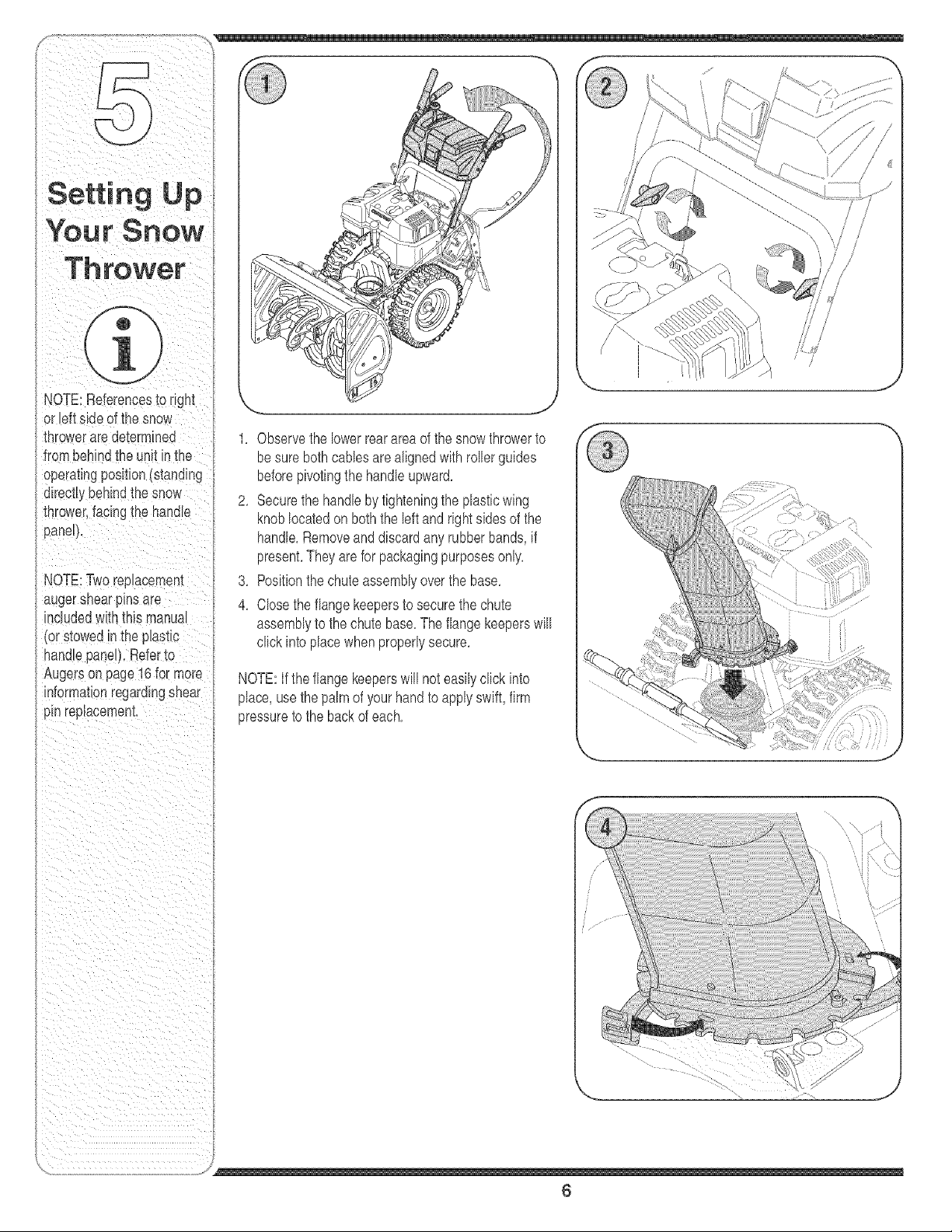
NOTE:References_ongm
or lett siaeof the snow
mrowerare ae[ermmea
tromoenmatne untin tne
operatingpos_on(stana_ng
directtybehindtne snow
thrower,facingtne nonage
paneH,
NOTE:Tworeptacemenl
augersnearpinsare
mcluaeawltn[nls manual
_orstowed nthe p_astLc
nanalepane), Referto
Augerson page16for more
mTorma_ronregardingshear
p_nreplacement,
J
1, Observethe lowerrearareaof the snowthrowerto
besure bothcablesare alignedwith rollerguides
beforepivotingthe handleupward,
2, Securethe handlebytighteningthe plasticwing
knoblocatedon boththe left and rightsidesof the
handle,Removeanddiscardany rubberbands,if
present,They are for packagingpurposesonly,
3, Positionthe chuteassemblyoverthe base,
4, Closethe flangekeepersto securethe chute
assemblyto the chutebase,Theflangekeeperswill
click intoplacewhenproperlysecure,
NOTE:Ifthe flangekeeperswill not easilyclick into
place,use thepalmof yourhandto applyswift,firm
pressureto the backof each,
,/
6
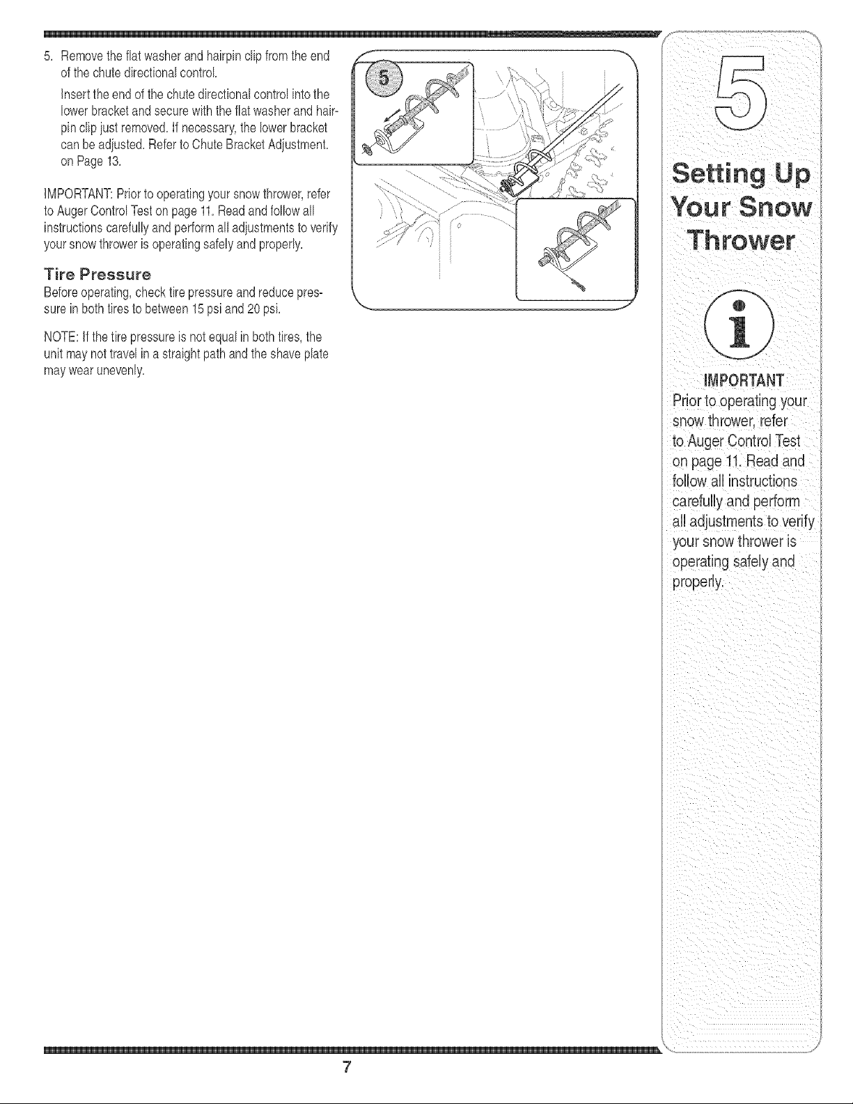
5, Removethe flat washerand hairpinclip from theend
of the chutedirectionalcontrol
insertthe endof the chute directionalcontrolintothe
lowerbracketandsecurewiththe flat washerand hair-
pinclipiust removed,If necessary',the lowerbracket
can beadiusted,Refer toChute BracketAdiustment,
on Page13,
iMPORTANT:Priorto operatingyoursnowthrower,refer
to AugerControlTeston page 11,Readand followall
instructionscarefullyandperformalladiustmentsto verify
yoursnowthroweris operatingsafelyand properly,
Tire Pressure
Beforeoperating,checktire pressureandreducepres-
sure in bothtires to between15psi and 20 psi,
NOTE:If thetire pressureis not equalin bothtires,the
unit maynottravelina straightpathand the shaveplate
maywearunevenly, iMPORTANT
Priorto operating your
snow thrower,refer
to Auger ControlTest
on page 11. Read and
follow all instructions
carefully and pertorm
all adoustmentsto verify
your snow thrower is
operating safely and
properly,
\
7
WARNING
Read, understand,
and follow aHinstruc-
tions and warnings
on the machine and
in this manual before
operating.
f
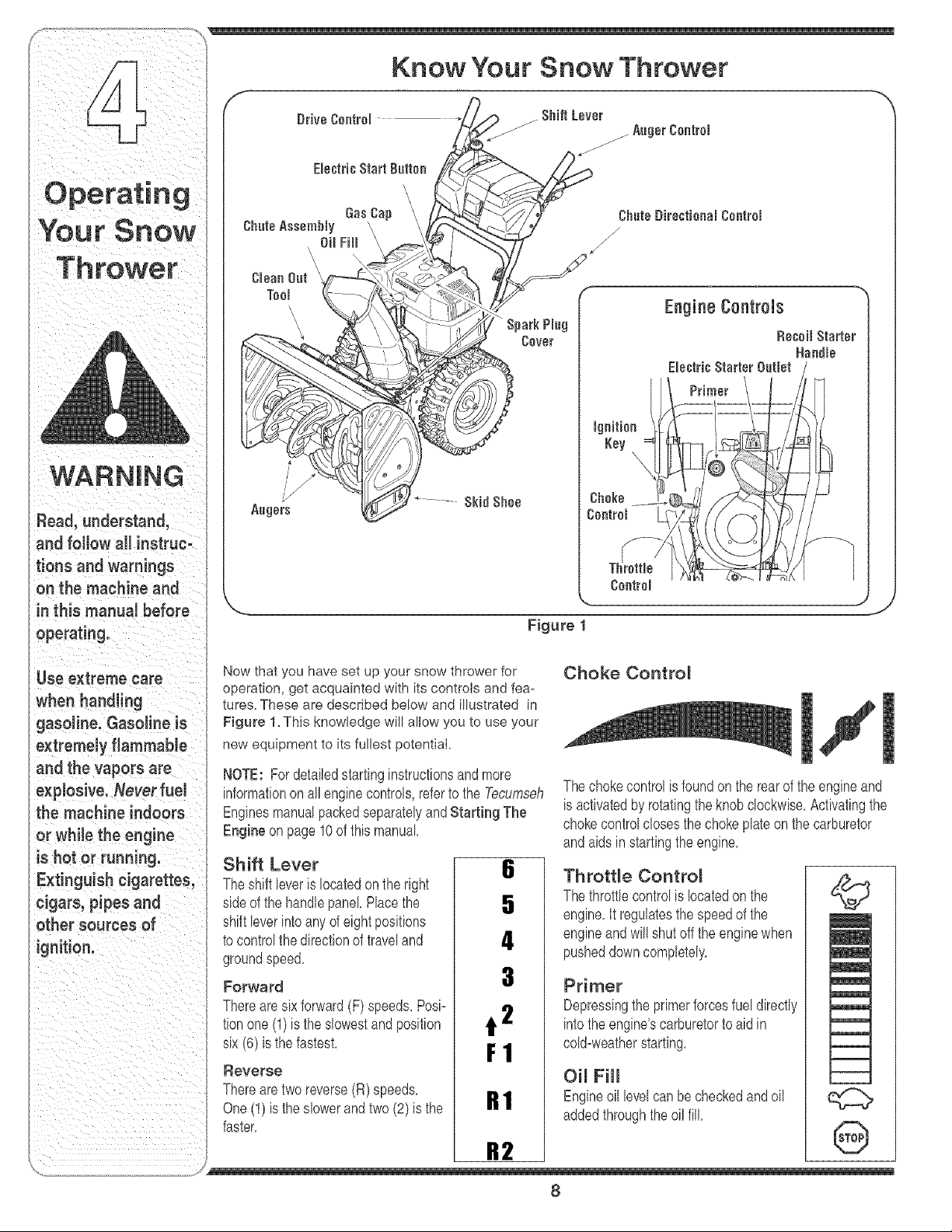
Know Your Snow Thrower
ShiftLever
/AugerControl
Choke
Controm
Engine Controls
Figure 1
Use extreme care
when handling
gasoline. Gasoline is
extremely flammable
and the vapors are
explosive. Never fuel
the machine indoors
or while the engine
is hot or running.
Extinguish cigarettes,
cigars, pipes and
)ther sources of
gnition.
Now that you have set up your snow thrower for
operation, get acquainted with its controls and fea-
tures. These are described be!ow and illustrated in
Figure 1. This knowledge will allow you to use your
new equipment to its fullest potential.
NOTE: Fordetailedstartinginstructionsandmore
informationon all enginecontrols,referto the Tecumseh
EnginesmanualpackedseparatelyandStarting The
Engine on page 10 of this manual
Shift Lever
Theshift leveris locatedonthe right
sideof the handlepanel Placethe
shift leverintoanyof eight positions
to controlthe directionof traveland
groundspeed.
Forward
Therearesixforward(F) speeds,Posi=
tionone (1) is the slowestand position
six (6) isthe fastest,
Reverse
Therearetworeverse(R) speeds,
One(1) is the slowerandtwo(2)is the
faster,
6
5
4
3
t 2
F1
R1
R2
Choke Contro_
Thechokecontrolis foundon the rearof the engineand
is activatedby rotatingthe knobclockwise.Activatingthe
chokecontrolclosesthe chokeplateon the carburetor
andaidsin startingthe engine.
Throttle Contro_
Thethrottlecontrolis locatedon the
engine,it regulatesthe speedof the
engineandwill shut off the enginewhen
pusheddowncompletely.
Primer
Depressingthe primerforcesfuel directly
intothe engine'scarburetorto aidin
cold=weatherstarting,
Oil Fill
Engineoil levelcan be checkedandoil
addedthroughthe oil fill.
©
!
!
@
/
8
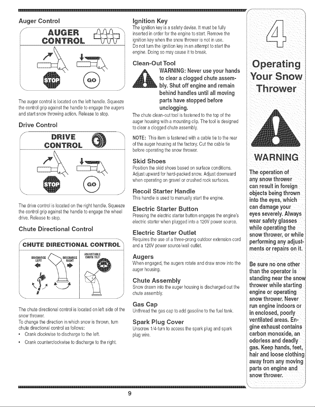
Auger Control
f
Theaugercontrolis locatedon the left handle,Squeeze
the controlgripagainstthe handleto engagetheaugers
andstartsnow throwingaction,Releaseto stop,
Drive Contro_
J
Y
Thedrivecontrolis locatedonthe right handle,Squeeze
the controlgripagainstthe handleto engagethewheel
drive,Releaseto stop,
Chute Directional ControJ
sCHUTE D_RECT_ONAL CONTROL _
ignition Key
The ignitionkeyis asafetydevise,It mustbefully
insertedin orderfor the engineto start,Removethe
ignitionkeywhenthesnowthroweris not in use,
Donot turnthe ignitionkeyinan attemptto startthe
engine,Doingso maycauseit to break,
CJean-Out TooJ
WARNING: Never use your hands
to clear a clogged chute assemo
bly. Shut off engine and remain
behind handles until all moving
parts have stopped before
unclogging.
The chutecleamouttool is fastenedto the topof the
augerhousingwith a mountingclip, Thetool is designed
to clear acloggedchuteassembly,
NOTE: Thisitemis fastenedwitha cane tie to the rear
of the augerhousingat thefactory,Cut the cane tie
beforeoperatingthe snow thrower,
Skid Shoes
Positionthe skidshoesbasedonsurfaceconditions,
Adiustupwardfor hard-packedsnow,Adiust downward
whenoperatingon gravelor crushedrocksurfaces,
Recoil Starter Handle
Thishandleis usedto manuallystart the engine,
Electric Starter Button
Pressingtheelectricstarterbuttonengagesthe engine's
electricstarterwhenpluggedintoa 120Vpowersource,
Electric Starter Outlet
Requiresthe useof a three-prongoutdoorextensioncord
anda 120Vpowersource/walloutlet,
BI$CHARGE
LEFT
#S
Thechutedirectionalcontrolis locatedonleftside of the
snowthrower,
Tochangethe directionin whichsnow is thrown,turn
chutedirectionalcontrolas follows:
*Crankclockwiseto dischargeto the left,
Crankcounterclockwiseto dischargeto the right,
Augers
Whenengaged,the augersrotateanddraw snowintothe
augerhousing,
Chute Assembly
Snowdrawnintothe augerhousingis dischargedoutthe
chuteassembly,
Gas Cap
Unthreadthe gas capto add gasolineto the fueltank,
Spark Plug Cover
Unscrew1/44urnto accessthe sparkplugandspark
plugwire,
9
Your Snow
WARNING
The operation of
any snow thrower
can result in foreign
objects being thrown
into the eyes, which
can damage your
eyes severely. Always
wear safety glasses
whiJe operating the
snow thrower, or while
performing any adjust-
ments or repairs on it.
Be sure no one other
than the operator is
standing near the sno_
thrower while starting
engine or operating
snow thrower. Never
run engine indoors or
in enclosed, poody
ventiJatedareas. En-
gine exhaust contains
carbon monoxide, an
odorless and deadly
gas. Keep hands,feet,
hair and loose dothim
away from any moving
parts on engine and
snow thrower.
WARNING
Read, understand,
and follow all instruc=
tions and warnings
on the machine and
in this manual before
operating.
Use extreme care
when handling
gasoline. Gasoline is
extremely flammable
and the vapors are
e×plosive. Never fuel
the machine indoors
or while the engine
is hot or running.
Extinguish cigarettes,
:igars, pipes and
other sources of
ignition.
if your home's wir-
ing system is not a
three-wire grounded
system, do not use
this electric starter
underanyconditions.
if your home
eJectdcal system
is grounded, but a
three-hoJe receptacle
isnot available, do
notuse yoursnow
thrower's electric
starter.
Gas & Oit Fill-Up
Servicethe enginewithgasolineand oil as instructedin
theTecumsehEnginesmanualpackedseparatelywith
yoursnowthrower,Readinstructionscarefully,
StartingThe Engine
1, Attachsparkplug wire tospark plug, Makecertainthe
metalloopon theend of the sparkplug wire(inside
the rubberboot)is fastenedsecurelyoverthe metal
tip onthe sparkplug,
2, Makecertainboththe augercontroland drivecontrol
areinthe disengaged(released)position,
3, Movethrottlecontrolupto FASTposition,Insert
ignitionkeyintoslot, Makesureit snaps intoplace,
Do notattemptto turn the key,
NOTE:The enginecannotstart unlessthe keyis
insertedintoignitionswitch,
Electric Starter
1, Determinethat your home'swiringis a three-wire
groundedsystem,Ask a licensedelectricianif you are
not certain,
WARNING: The optionat electric
starter is equipped with a
grounded three-wire power cord
and plug, and is designed to op-
erate on 120 volt AC household
current, it must be used with a
properly grounded three-prong
receptacle at all times to avoid
the possibility of electric shock.
Follow all instructions carefully
prior to operating the electric
starter.
if youhavea groundedthree-prongreceptacle,proceed
as follows:
1, Plugthe extensioncord intothe outlet locatedon the
engine'ssurface,Plugthe otherendof extensioncord
intoa three-prong120-volt,grounded,ACoutlet in a
wellwentilatedarea,
2, Rotatechokecontrolto FULLchoke position(fora
coldenginestart),
NOTE:If the engineis alreadywarm,placechokecontrol
in theOFF positioninsteadof FULL,
3, Pushthe primertwoor threetimesfor cold engine
start,makingsureto covervent hole in the centerof
the primerwhen pushing,
NOTE:DO NOTuseprimerto restarta warmengine
aftera shortshutdown,
4, Pushstarterbuttonto start engine,
5, Oncethe enginestarts,immediatelyreleasestarter
button,
6, As the enginewarms,slowlyrotatethe chokecontrol
to theOFFposition,Ifthe enginefalters,quicklyrotate
the chokecontrolbackto FULLandthenslowlyinto
the OFFpositionagain,
7, Whendisconnectingthe extensioncord,always
unplugtheend atthe three-prongwalloutlet before
unpluggingthe oppositeendfromthesnowthrower,
Recoil Starter
1, Rotatechokecontrolto FULLchokeposition(cold
enginestart),
NOTE:If the engineis alreadywarm,placechokecontrol
inthe OFFpositioninsteadof FULL,
2, Pushthe primertwoor threetimesfor coldengine
start, makingsure to coverventhole in the centerof
the primerwhenpushing,
NOTE:DO NOTuse primerto restarta warmengine
aftera short shutdown,
NOTE:Additionalprimingmaybe necessaryif the
temperatureis below15° Fahrenheit,
3, Graspthe recoilstarterhandleandslowlypull the
ropeout,At the pointwhereit becomesslightlyharder
to pullthe rope,slowlyallowthe ropeto recoil
4, Pullthe starterhandlewitha firm, rapidstroke,Do not
releasethe handleandallowit to snap back,Keepa
firm holdon the starterhandleand allowit to slowly
recoil
5, As the enginewarms,slowlyrotatethe chokecontrol
to theOFFposition,Ifthe enginefalters,quicklyrotate
the chokecontrolbackto theFULLpositionand then
slowly intothe OFFpositionagain,
NOTE:Allowthe engineto warmupfor afew minutes
afterstarting,The enginewill not developfullpoweruntil
it reachesoperatingtemperatures,
Stopping The Engine
Runenginefor a few minutesbeforestoppingto help dry
off any moistureon the engine,
To helppreventpossiblestarterfreeze=up,proceedas
follows:
E_ectric Starter
1, Connectextensioncord to the electdcstarteroutlet
on the engine,thento 120volt AC outlet,
2, Withthe enginerunning,pushthestarter buttonand
allow thestarterfor spin forseveralseconds,The
noisemadeby the starteris normal The engine's
starter is not beingharmed,
3, Whendisconnectingthe extensioncord,always
unplugtheend atthe three-prongwalloutlet before
unpluggingthe oppositeendfromthesnowthrower,
4, Movethrottlecontrolto STOPposition,
5, Removethe ignitionkey,
J
10

6. Wipeall snowand moisturefrom the areaaroundthe
engineas wellas the areain and aroundthedrive
controlandaugercontrol Also,engageand release
bothcontrolsseveraltimes.
NOTE: Keepthe keyin a safe place.The enginecannot
start withoutthe ignitionkey.
Recoil Starter
1. Withenginerunning,pull starterrope with a rapid,
continuousfull arm strokethreeor fourtimes. Pulling
the starterropewill producea loudclatteringsound,
whichis not harmfulto engine.
2. Movethrottlecontrolto STOPposition.
3. Removethe ignitionkey.
NOTE: Keepthe keyin a safe place.The enginecannot
start withoutthe ignitionkey.
4. Wipeall snowand moisturefrom the areaaroundthe
engineas wellas the areain and aroundthedrive
controlandaugercontrol Also,engageand release
bothcontrolsseveraltimes.
Chute Clean-Out TooJ
Thechutecleamouttoolis convenientlyfastenedto the
rearof the augerhousingwith a mountingclip.Should
snowand icebecomelodged in the chuteassembly
duringoperation,proceedas followsto safelycleanthe
chuteassemblyandchuteopening:
1. ReleaseboththeAugerControland the DriveControl
2. Stopthe engineby removingthe ignitionkey.
3. Removethe cleamouttool fromthe clip whichsecures
it to the rearof the augerhousing.
4. Usetheshovel=shapedendof thecleamouttool to
dislodgeandscoop anysnowand ice whichhas
formedinand nearthe chute assembly.
5. Refastenthe cleamouttool to the mountingclip on the
rearof the augerhousing,reinserttheignitionkeyand
startthe snowthrower'sengine.
6. Whilestandinginthe operator'sposition(behindthe
snowthrower),engagethe augercontrolfor a few
secondsto clearany remainingsnowand ice from the
chuteassembly.
To Engage Drive
1. Withthethrottlecontrolin the Fast(rabbit)position,
moveshift leverintooneof the six forward (F)
positionsor tworeverse(R) positions.Selecta speed
appropriatefor the snowconditionsand a paceyou're
comfortablewith.
2. Squeezethe auger controlagainstthe handleand the
augerswill turn.Releaseit and the augerswill stop.
3. Squeezethe drivecontrol againstthe handlethe snow
throwerwillmove.Releaseit and drivemotionwill
stop.
To Engage Augers
1. To engagethe augersand start throwingsnow,
squeezethe augercontrolagainstthe left handle.
Releaseto stopthe augers.
Auger Control Test
Performthe followingtestbeforeoperatingyour snow
throwerfor the first timeandat thestart of eachwinter.
Checkthe adiustmentof the augercontrolas follows:
1. When theauger controlis releasedand in the
disengaged"up"position,the cableshouldhavevery
littleslack.ItshouldNOTbetight.
2. In a well=ventilatedarea,start thesnowthrowerengine
as instructedonthe previouspage.Makesurethe
throttleis setin the FAST )osition.
3. While standingin the operator'sposition(behindthe
snowthrower),engagethe auger.
4. Allowtheaugerto remainengagedfor approximately
ten (10)secondsbeforereleasingtheauger control.
Repeatthis severaltimes.
5. With thethrottlecontrol in the FAST(rabbit)position
andthe augercontrolin thedisengaged"up"position,
walkto thefrontof the machine.
6. Confirmthatthe augerhas completelystopped
rotatingandshowsNO signsof motion.If the auger
showsANYsignsof rotating,immediatelyreturnto the
operator'spositionandshutoff the engine.Waitfor
ALLmovingpartsto stop beforere=adiusfingthe auger
control.
7. To readiustthecontrolcable, loosenthe upperhex nut
onthe augercable bracket.
8. Positionthe bracketupwardto providemoreslack (or
downwardto increasecabletension).SeeFigure2.
9. Retightenthe upper hexnut.
10.RepeatAuger Control Testto verifyproperadiust=
menthasbeenachieved.
\
\ \\
Figure 2
11
When selecting a
Dr!re Speed, use the
smowerSpeeds
you ate comfortable
and familiar with the
operation of the snow
WARNING
Never use your hands
to clean snow and
ice from the chute
assembly or auger
housing.
The muffler, engine
and surrounding
areas become hot
and can cause a
burn. Do not touch.
Making
Read, understand,
and follow all instruc-
tions and warnings
on the machine and
in this manuaJ before
_perating,
Never attempt to
make any adjust-
ments while the
engine is running,
except where speci=
fied in operator's
manual
Auger Controm
Referto AugerControlTeston Page11to adiustthe
augercontrol
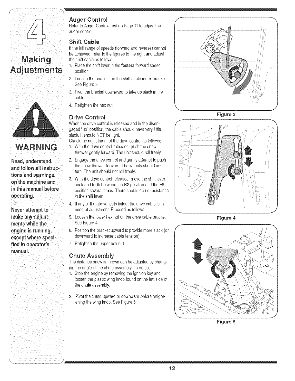
Shift Cable
if thefull rangeof speeds(forwardandreverse)cannot
beachieved,referto thefigures to the rightand adiust
theshift cableas follows:
1, Placethe shiftleverin the fastest forwardspeed
position,
2, Loosenthe hex nuton the shiftcable indexbracket,
SeeFigure3,
3, Pivotthe bracketdownwardto takeupslack in the
cable,
4, Retightenthe hexnut,
Drive Control
Whenthedrive controlis releasedandin the disen=
gaged"up"position,the cableshouldhaveverylittle
slack,ItshouldNOTbetight,
Checkthe adiustmentof the drivecontrolas folfows:
1, Withthe drivecontrolreleased,pushthe snow
throwergentlyforward,The unitshouldfelt freely,
2, Engagethedrivecontrolandgently attemptto push
the snowthrowerforward,The wheelsshouldnot
turn,The unit shouldnot roll freely,
3, With the drivecontrol released,movethe shift lever
backandforth betweenthe R2 positionand the F6
positionseveraltimes,Thereshouldbe noresistance
inthe shift lever,
4, if anyof the abovetestsfailed,the drivecabteis in
needof adiustment,Proceedas follows:
5, Loosenthe lowerhexnut onthe drivecable bracket,
SeeFigure4,
6, Positionthe bracketupwardto providemoreslack (or
downwardto increasecabletension),
7, Retightenthe upperhexnut,
Chute Assembly
Thedistancesnowis throwncan beadiustedby chang=
ingthe angleof thechuteassembly,Todo so:
1, Stopthe engineby removingthe ignitionkeyand
loosentheplasticwing knobfound onthe leftside of
the chuteassembly,
2, Pivotthe chuteupwardor downwardbeforeretight=
eningthe wing knob,SeeFigure5,
f
Figure 4
Figure 5
12
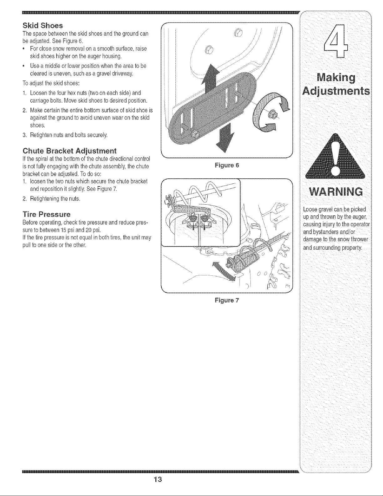
beadiusted,See Figure6,
Forclosesnowremovalona smoothsurface,raise
skidshoeshigheron the augerhousing,
• Usea middleor lowerpositionwhentheareato be
clearedis uneven,suchas agraveldriveway,
Toadiustthe skidshoes:
1, Loosenthe four hexnuts (two on eachside) and
carriagebolts,Moveskidshoesto desiredposition,
2, Makecertainthe entire bottomsurfaceof skidshoeis
againstthe groundto avoidunevenwearonthe skid
shoes,
3, Retightennutsand boltssecurely,
Chute Bracket Adjustment
If the spiralat the bottomof the chute directionalcontrol
is not fullyengagingwiththe chuteassembly,the chute
bracketcan beadiusted,Todoso:
1, loosenthe two nutswhich securethe chute bracket
andrepositionit slightly,SeeFigure7,
2, Refighteningthenuts,
Tire Pressure
Beforeoperating,checktire pressureand reducepres=
sureto between15psiand 20 psi,
if the tire pressureis not equalin bothtires,the unit may
pullto oneside or the other,
Figure6
Figure 7
13
Loosegravelcan be picked
uparia mrown bythe auger,
causing_n/uryto the operator
_ndbt sl:anaersana/or
]amageto [ne snowthrower
anasurrouna_ngproperty,
repairing,or nspeat.
disengageaH
controls and stop
moving parts have
cam toaco pl to
rubberfriction wheel
Engine
Referto the separateTecumsehEnginesmanual
packedwithyourunitfor all enginemaintenance,
Lubrication
Engine
Referto the separateTecumsehEnginesmanual
packedwithyourunitfor all enginelubricationinstruc-
tions,
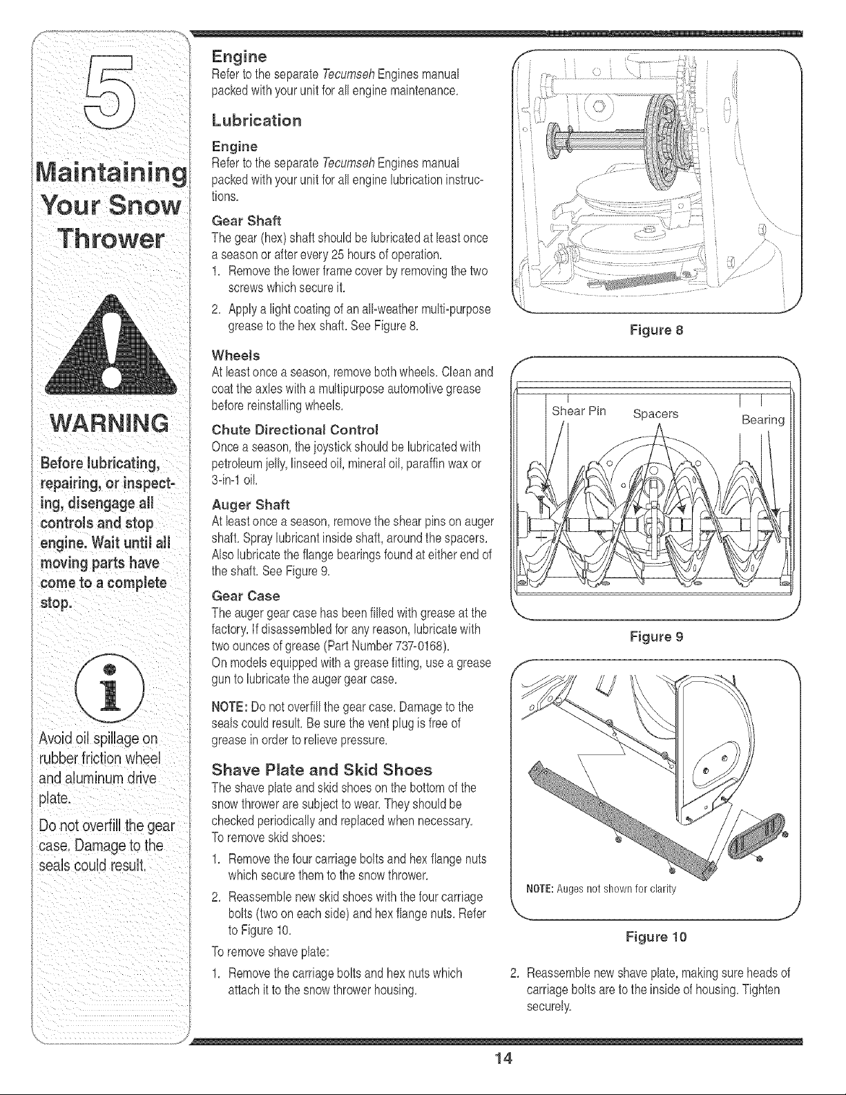
Gear Shaft
The gear(hex)shaft shouldbelubrbatedat bast once
a seasonor after every25 hoursof operation,
1, Removethelowerframecoverby removingthe two
screwswhichsecureit,
2, Applya lightcoatingof an aBweathermulti-purpose
greaseto the hex shaft,SeeFigure8,
WheeJe
At bast once a season,removeboth wheeB,Cleanand
coattheaxles with a multipurposeautomotivegrease
beforereinstallingwheels,
Chute Directional Control
Oncea season,theioystickshouldbe lubrbatedwith
petrobumielly,linseedoil, mineraloil, paraffinwaxor
3-in-1oil,
Auger Shaft
At leastonce a season,removethe shearpinson auger
shaft,Spraylubricantinsideshaft,aroundthe spacers,
ABelubricatethe flangebearingsfoundat eitherend of
the shaft,See Figure9,
Gear Case
The augergearcase has beenfilled with greaseat the
factory,If disassembledfor anyreason,lubricatewith
twoouncesof grease(PartNumber737_0168),
On modelsequippedwitha greasefitting, usea grease
gunto lubrbatethe auger gear case,
NOTE: Donot overfillthe gearcase, Damageto the
sealscould resuL Besurethe ventplugis freeof
greaseinorder to relievepressure,
Shave P_ate and Skid Shoes
The shaveplateandskid shoeson the bottomof the
snowthroweraresubiectto wear,Theyshouldbe
checkedperiodicallyandreplacedwhennecessary,
To removeskidshoes:
1, Removethefour carriageboltsandhexflangenuts
whichsecurethemto the snowthrower,
2, Reassemblenewskidshoeswiththefour carriage
bolts(two oneach side)andhexflangenuts, Refer
to Figure10,
To removeshaveplate:
1, Removethecarriageboltsand hexnutswhich
attachit to the snowthrowerhousing,
f
f
Figure 8
I
Shear Pin Spacers
\
\\
\
/
>
/
Figure 9
NOTE:Augesnot shownfor clarity
Figure 10
I T
Bearing
2, Reassemblenewshaveplate,makingsureheadsof
carriageboltsareto the insideof housing,Tighten
securely,
J
14
//
//
'_ ///
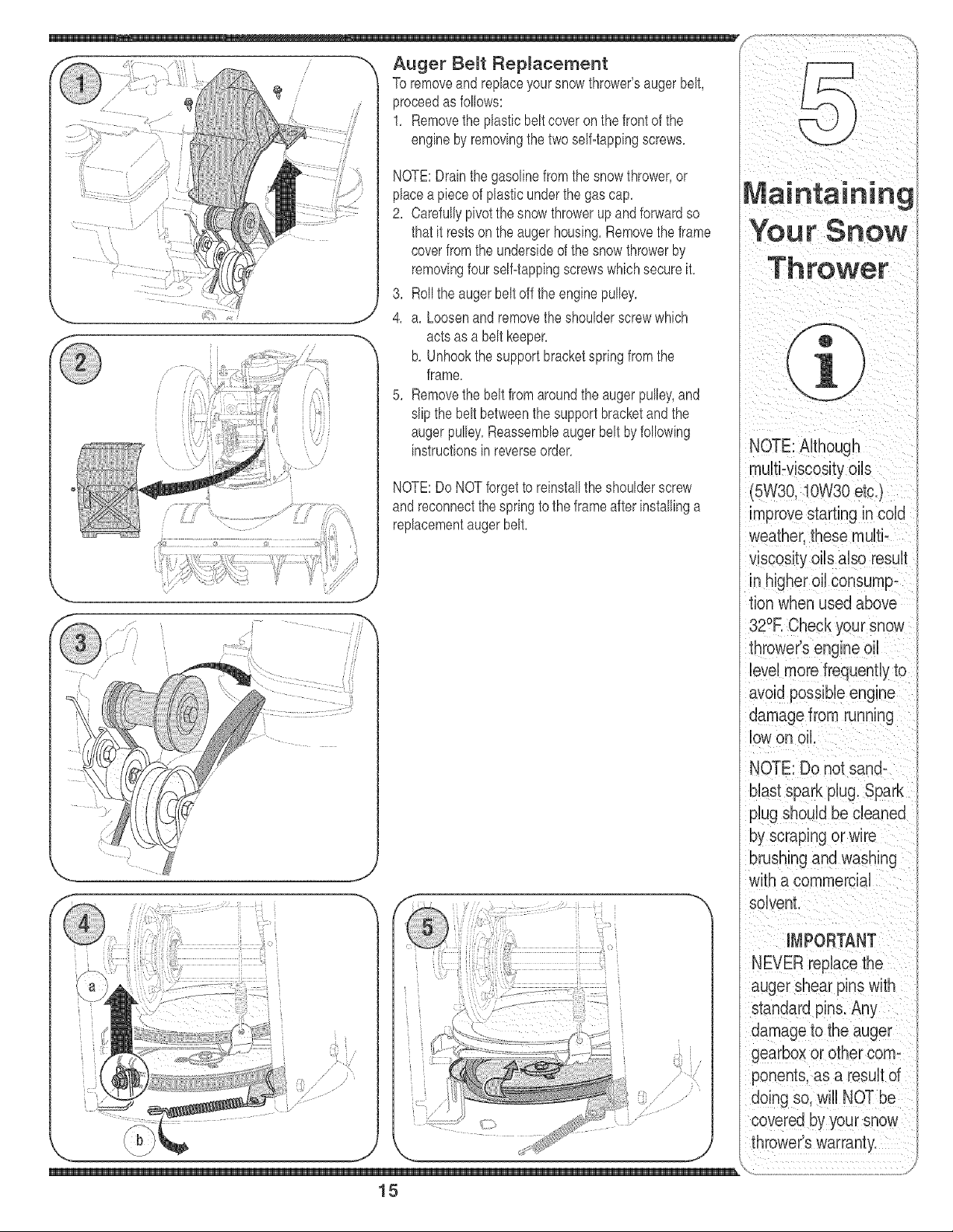
Auger Belt Replacement
To removeand replaceyoursnowthrower'saugerbelt,
proceedas follows:
1, Removethe plasticbelt coveronthe frontof the
engineby removingthe twoself-tappingscrews,
NOTE:Drainthe gasolinefromthe snowthrower,or
placea pieceof plasticunderthe gas cap,
2, Carefullypivotthe snowthrowerup andforwardso
thatit restsonthe augerhousing,Removethe frame
coverfromthe undersideof the snow throwerby
removingfourself=tappingscrewswhichsecureit,
3, Rollthe augerbeltoff the enginepulley,
4, a, Loosenandremovethe shoulderscrewwhich
actsas a belt keeper,
b, Unhookthe supportbracketspringfromthe
frame,
5, Removethe belt fromaroundthe augerpulley,and
slip the beltbetweenthesupportbracketand the
augerpulley,Reassembbaugerbeltby following
instructionsinreverseorder,
NOTE:Do NOTforgetto reinstallthe shoulderscrew
andreconnectthespringto the frameafter installinga
replacementaugerbelt,
tion when used above
321F,Check your snow
NEVERreplace
theaugershear
pinswithanything
otherthanOEM
PartNo.788-04124
replacementshear
todosowillNOTbe
coveredbyyoursnow
thrower'swarranty.
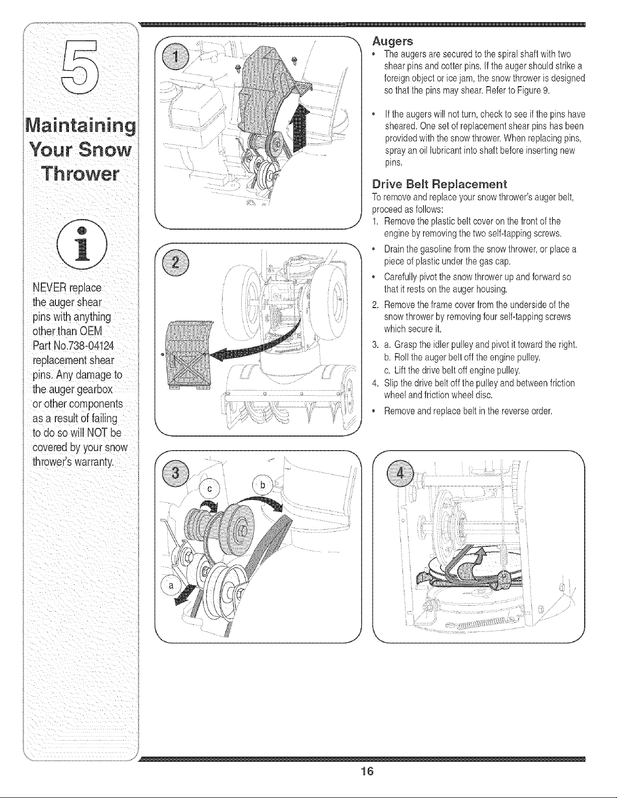
-_ Augers
, Theaugersaresecuredto thespiral shaftwithtwo
shearpinsandcotter pins,if the augershouldstrikea
foreignobjector icejam, the snowthroweris designed
so thatthe pinsmayshear,Referto Figure9,
• if theaugerswill notturn,checkto seeif the pinshave
sheared,Onesetof replacementshearpins has been
providedwiththesnowthrower,When replacingpins,
sprayan oil lubrbant intoshaft beforeinsertingnew
pins,
Drive Belt Replacement
To removeandreplaceyoursnow thrower'saugerbelt,
proceedas follows:
j 1, Removetheplasticbelt coveron thefront of the
engineby removingthe twoseBtappingscrews,
, Drainthe gasolinefromthesnowthrower,or placea
pieceof plasticunderthe gas cap,
, Carefullypivotthe snowthrowerup and forwardso
thatit restson the augerhousing,
2, Removetheframecoverfromthe undersideof the
snowthrowerby removingfourseBtappingscrews
whichsecureit,
3, a, Graspthe idlerpulby andpivotit towardthe right,
b, Rollthe augerbeltoff the enginepulley,
c, Liftthe drivebelt offenginepulby,
4, Slipthe drivebeltoff the pulleyand betweenfriction
wheelandfrictionwheeldisc,
Removeandreplacebelt inthe reverseorder,
i'\ •
i iii:iii
i'i
\
.........
:: ........... .......... t '_}; : ......
J
16
/
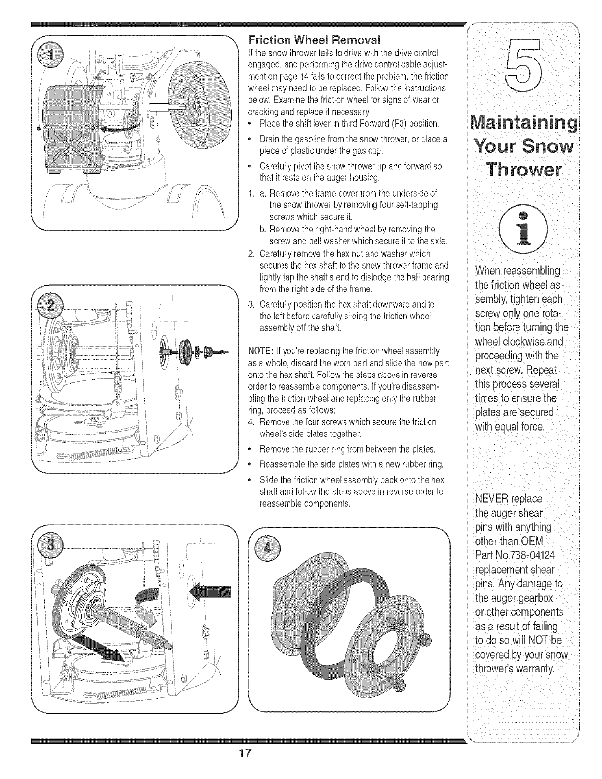
Friction Whee_ Remova_
if the snowthrowerfailsto drivewiththe drivecontrol
engaged,and performingthedrive controlcameadiust-
menton page 14fails to correctthe problem,the friction
wheelmayneedto bereplaced,Followthe instructions
below,Examinethe frictionwheelfor signsof wearor
crackingandreplaceif necessary
o Placetheshift bver in third Forward(F3) position,
o Drainthe gasolinefromthe snow thrower,or placea
pieceof plasticunderthe gas cap,
o Carefullypivotthe snowthrowerup andforwardso
thatit restsonthe augerhousing,
1, a, Removetheframecoverfromthe undersideof
the snowthrowerby removingfourself-tapping
screwswhichsecureit,
b, Removethe right-handwheelby removingthe
screwandbellwasherwhichsecureit to the axle,
2, Carefullyremovethe hexnut andwasherwhich
securesthe hexshaft to the snowthrowerframeand
lightlytap the shaft'sendto dislodgethe ballbearing
fromthe rightsideof the frame,
3, Carefullypositionthe hexshaftdownwardandto
the bft beforecarefullyslidingthefrictionwheel
assemblyoff theshaft,
NOTE: Ifyou'rereplacingthe frictionwheelassembly
as a whob, discardtheworn partand slide the newpart
ontothe hexshaft,Followthe stepsabovein reverse
orderto reassemblecomponents,If you'redisassem-
blingthefrictionwheeland replacingonly the rubber
ring, proceedas follows:
4, Removethe four screwswhichsecurethe friction
wheel'sside platestogether,
o Removethe rubberring from betweenthe plates,
o Reassemblethe side plateswitha newrubberring,
Slidethefrictionwheelassemblybackontothe hex
shaftandfollow thestepsabovein reverseorder to
reassembbcomponents,
When reassembling
the friction wheeHas-
sembHy,tighten each
screw only one rota-
tion beforeturning the
wheeHclockwise and
proceeding with the
next screw. Reoeat
this process several
times to ensure the
plates are secured
with equal force,
NEVER repuace
the auger shear
pins with anything
other than OEM
Part No.738-04124
replacementshear
pins. Any damage to
the auger gearbox
or other components
as a result of failing
to do so will NOT be
covered by your snow
thrower's warranty.
\
17
WARNING
Never store snow
thrower with fueJ
in tank indoors or
in poody ventilated
areas, where fuel
fumes may reach an
open flame, spark
or pilot light as on a
furnace, water heater,
clothes dryer or gas
appliance,
Drain fuel into an
approved container
outdoors, away from
any open flame. Be
certain engine is
cool. Do nol smoke.
Fuel left in engine
during warm weather
deteriorates and will
cause serious
starting problems.
Do not drain
carburetor ff
using fuel stabilizer.
Never use engine or
carburetor cleaning
products in the fuel
tank or permanent
damage may occur.
If thesnowthrowerwill not be usedfor 30 daysor longer,
orif it is the endof the snowseasonwhenthe lastpos=
sibilityof snowis gone,the equipmentneedsto be stored
properly.Followstorageinstructionsbelowto ensuretop
performancefromthe snowthrowerfor many moreyears.
Preparing Engine
WARNING: Never store snow
thrower with fuel in tank indoors
or in poorty ventilated areas,
where fuel fumes may reach an
open flame, spark or pilot tight
as on a furnace, water heater,
clothes dryer or gas appliance.
NOTE:It is importantto preventgum depositsfromform=
ingin essentialfuelsystempartsof the enginesuch as
thecarburetor,fuel filter,fuel hoseor tank duringstorage.
CAUTION:Alcoholblendedfuels(calledgasoholorusing
ethanolor methanol)can attractmoisturewhich leadsto
separationandformationof acids duringstorage.Acidic
gascan damagethe fuelsystemof anenginewhile in
storage.
To avoidengineproblems,the fuel systemshouldbe
emptiedbeforestoragefor30 days or longer.Follow
theseinstructionsto prepareyoursnow throwerfor
storage:
WARNING: Drain fuel into an ap-
proved container outdoors, away
from any open flame. Be certain
engine is cool. Do not smoke.
Fuel left in engine during warm
weather deteriorates and will
cause serious starting problems.
1. Removeall gasolinefrom the carburetorandthe fuel
tank to preventgumdepositsfromformingon these
partsand harmingthe engine.
2. Runthe engineuntilthe fuel tankis emptyand it stops
dueto lackof fuel.
3. Draincarburetorby pressingupwardon bowldrain,
locatedbelowthe carburetorcover(referto the
Tecumsehenginemanualfor moredetailedinstruc=
fion).
WARNING: Do not drain carbure-
tor if using fuel stabilizer. Never
use engine or carburetor cleaning
products in the fuel tank or
permanent damage may occur.
NOTE:Fuelstabilizer(suchas STA=BIL)is anaccept=
ablealternativein minimizingtheformationof fuel gum
depositsduringstorage.Add stabilizerto gasolinein fuel
tankor storagecontainer.Alwaysfollow mix ratiofoundon
stabilizercontainer.Runengineat least 10 minutesafter
addingstabilizerto allowit to reachthe carburetor.Do not
draincarburetorif usingfuelstabilizer.
4. Removethe spark plugand pourone (1)ounceof
engineoil throughthespark plug hole intothe cylinder.
Coversparkplughole with a rag and crankthe engine
severaltimesto distributethe oil. Replacesparkplug.
NOTE:Referto the Tecumsehenginemanualfor more
informationon preparingthe snowthrowerenginefor
storage.
Preparing Snow Thrower
1. Whenstoringthe snow throwerin an unventilatedor
metalstorageshed,care shouldbe takento rustproof
the equipment.Usinga lightoil or silicone,coatthe
equipment,especiallyany chains,springs,bearings
andcables.
2. Removeall dirt from exteriorof engineandequipment.
3. Followlubricationrecommendationson page12.
4. Storeequipmentina clean,dry area.
18
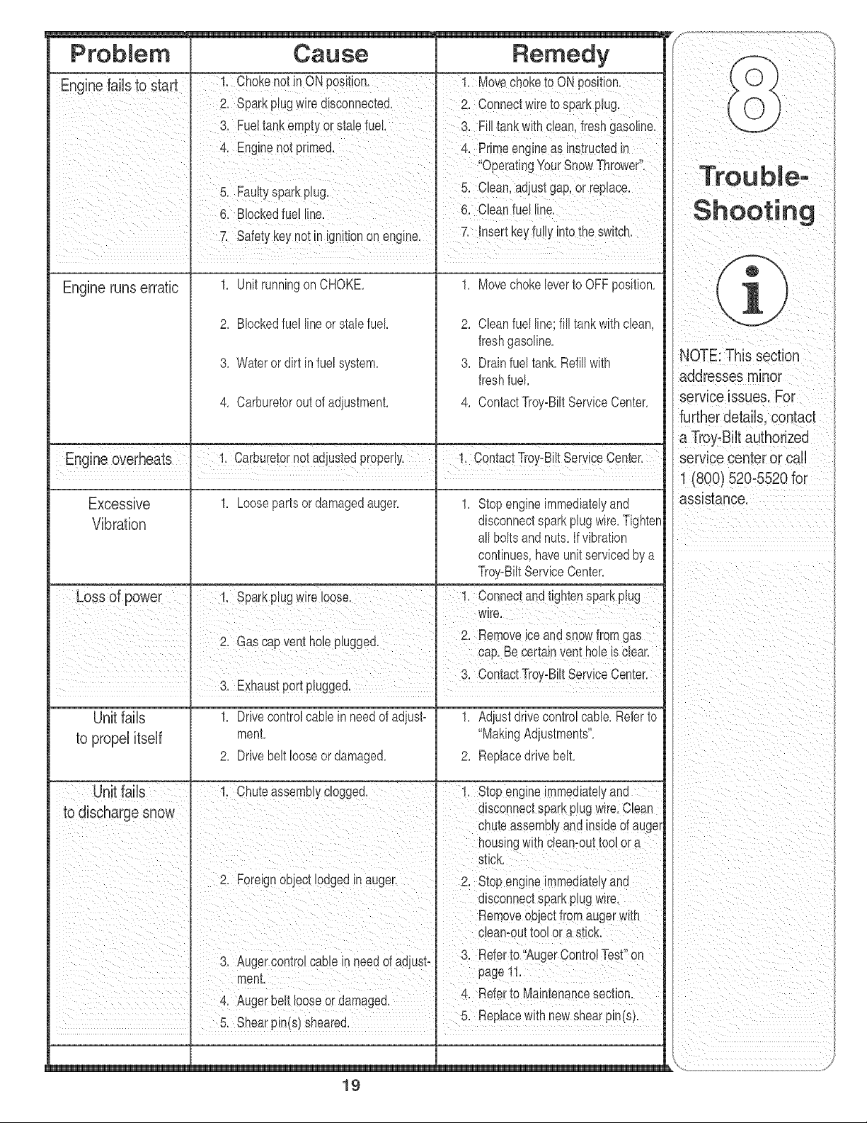
ProbHem Cause Remedy
Ermine faiUsto start !. Chokenot inON position. 1. Movechoketo ON position.
' 2. Sparkplugwire disconnected. 2. Connectwire to sparkplug.
3. Fueltankemptyor stalefuel. 3. Filltankwith clean,freshgasoline.
4. Enginenot primed. 4. Primeengneas instructedin
OperatingYourSnowThrower.
5. Fautyspark pug. 5. Clean adiustgap or replace.
6. Blockedfuel line. 6. Cleanfuel line.
7. Safetykeynotin ignitionon engine. 7. insertkeyfully intothe swtch.
1
Engine runs erratic 1. Unit runningon CHOKE. 1. Movechokeleverto OFFposition.
2. Blockedfuel lineor stab fuel 2. Cleanfuel line;fill tankwithclean,
freshgasoline.
3. Wateror dirt in fuel system. 3. Drainfuel tank.Refillwith
freshfuel.
4. Carburetoroutof adiustment. 4. ContactTroy-BiltServiceCenter.
Engne overheats 1 CarburetornotadjustedproperY 1 1 ContactTroy-Bt Servce Center
Excessive 1. Loosepartsor damagedauger. 1. Stopengineimmediatelyand
Vibration disconnectsparkplugwire.Tighten
all boltsandnuts.If vibration
continues,haveunitservicedby a
Troy_BiltServiceCenter.
3. Exhaustport plugged.
Unitfails
to propelitself
1. Drivecontrolcable in needof adjust-
ment.
2. Drivebelt looseor damaged.
B
1. Adiustdrivecontrolcable.Refer to
"MakingAdjustments".
2. Replacedrivebelt.
Removeobjectfromaugerwith
NOTE:This section
addresses minor
service issues. For
further details, contact
a Troy-Bilt authorized
service center or sail
1 (800) 520-5520 for
assistance.
19
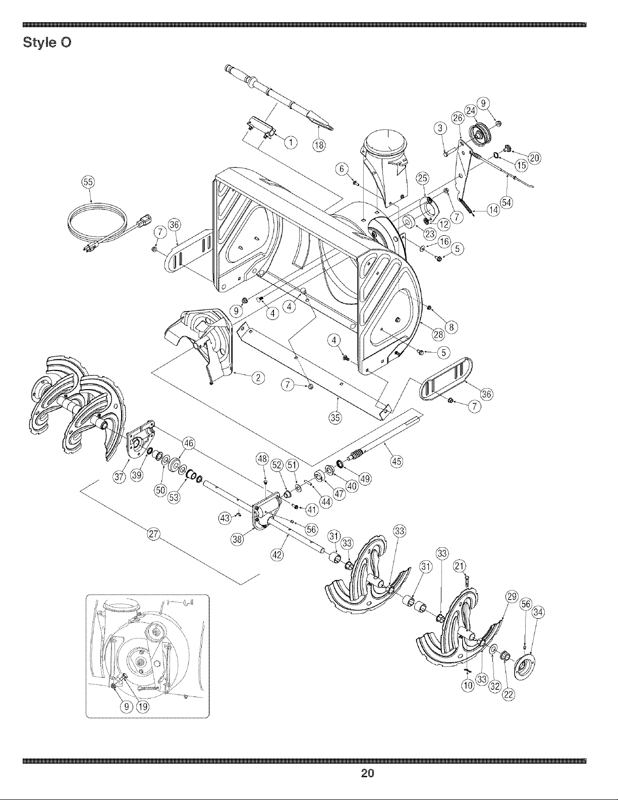
StyWe 0
20
, _i _i i_ G i _III
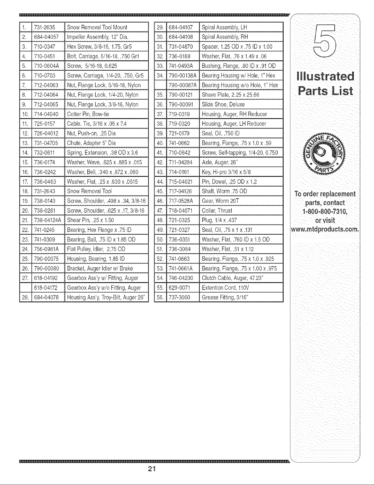
1, 731-2635 SnowRemovalToolMount 29, 684-04107 SpiralAssembly,LH
j2, 684-04057 JmpellerAssembly,12"Dia,
j 3, 710-0347 HexScrew,3/8q6, 1,75,Gr5
4, 710-0451 Bolt,Carriage,5/16q8, ,750Grl
5, 710-0604A Screw, 5/16q8, 0,625
6, 710_0703 Screw,Carriage,1/4_20,,750,Gr5
7, 712-04063 Nut,FlangeLock,5/16q8, Nylon
8, 712_04064 Nut,FlangeLock,1/4_20,Nylon
9, 712-04065 Nut,FlangeLock,3/8q6, Nylon
10, 714-04040 CotterPin,Bow-tie
11, 725-0157 Cable,Tie, 3/16x ,05x 7,4
12, 726_04012 Nut,Push-on,,25 Dia
13, 731-04705 Chute,Adapter5" Dia
14, 732-0611 Spring,Extension,,38OD x 3,6
15, 736-0174 Washer,Wave,,625x ,885x ,015
16, 736-0242 Washer,Bell,,340 x ,872x ,060
17, 736-0463 Washer,Flat,,25 x ,630x ,0515
18, 731-2643 SnowRemovaITool
19, 738-0143 Screw,Shoulder,,498x ,34,3/8q6
20, 738-0281 Screw,Shoulder,,625x ,17,3/8q6
21, 738-04124A ShearPin,,25 x 1,50
22, 741-0245 Bearing,Hex Flangex ,75ID
23, 741-0309 Bearing,Ball,,75 ID x 1,85OD
24, 756_0981A Flat Pulley,Idler, 2,75OD
25, 790-00075 Housing,Bearing,1,85ID
26, 790-00080 Bracket,AugerIdlerw/Brake
27, 618-04192 GearboxAss'yw/Fitting, Auger
618-04172 GearboxAss'yw/o Fitting,Auger
28, 684-04078 HousingAss'y,Troy-Bilt,Auger26"
30, 684-04108 SpiralAssembly,RH
31, 731-04870 Spacer,1,25ODx ,75IDx 1,00
32, 736-0188 Washer,Flat,,76x 1,49x ,06
33, 741_0493A Bushing,Flange,,80ID x ,91OD
34, 790-00138A BearingHousingw/Hob, l"Hex
790-00087A BearingHousingw/o Hob, 1"Hex
35, 790-00121 ShavePlate,2,25x 25,66
36, 790_00091 SlideShoe,Deluxe
37, 719-0319 Housing,Auger,RH Reducer
38, 719-0320 Housing,Auger,LH Reducer
39, 721-0179 Seal,Oil, ,750ID
40, 741-0662 Bearing,Flange,,75x 1,0x ,59
41, 710-0642 Screw,Self-tapping,1/4-20,0,750
42, 711-04284 Axle,Auger,26'
43, 714-0161 Key,Hi-pro3/16x 5/8
44, 715-04021 Pin, Dowel,,25 ODx 1,2
45, 717_04126 Shaft,Worm,75OD
46, 717-0528A Gear,Worm20T
47, 718-04071 Collar,Thrust
48, 721-0325 Plug, 1/4x ,437
49, 721-0327 Seal,Oil, ,75x 1 x ,131
50, 736_0351 Washer,Flat,,760ID x 1,50D
51, 736-3084 Washer,Flat,,51x 1,12
52, 741-0663 Bearing,Flange,,75x 1,0x ,925
53, 741-0661A Bearing,Flange,,75x 1,00x ,975
54, 746_04230 ClutchCable,Auger,47,23"
55, 629_0071 ExtentionCord,110V
56, 737-3000 GreaseFitting,3/16"
parts, contact
t'800_800-7310,
or Visit
Wwwlmtdpioducts:com:
\
21
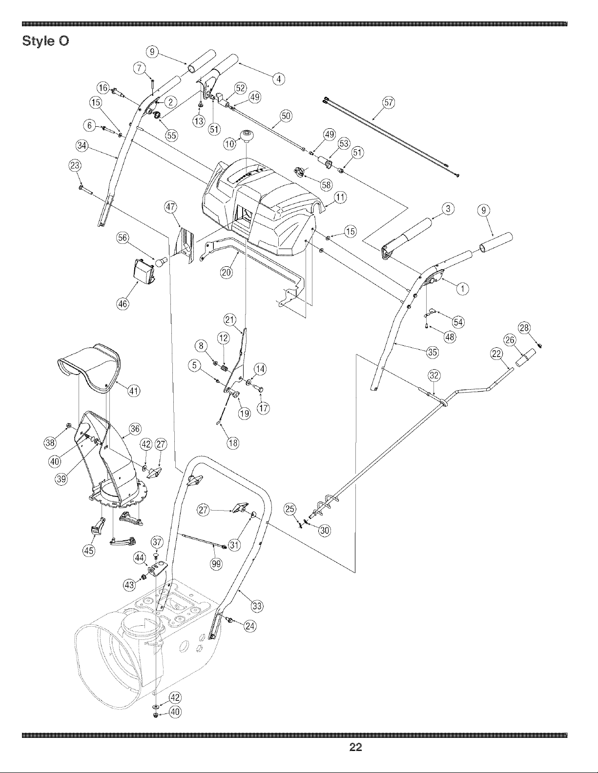
StyJe 0
-@
®
/
,,,,/"
22
, _i _i i_ iii_ i _III
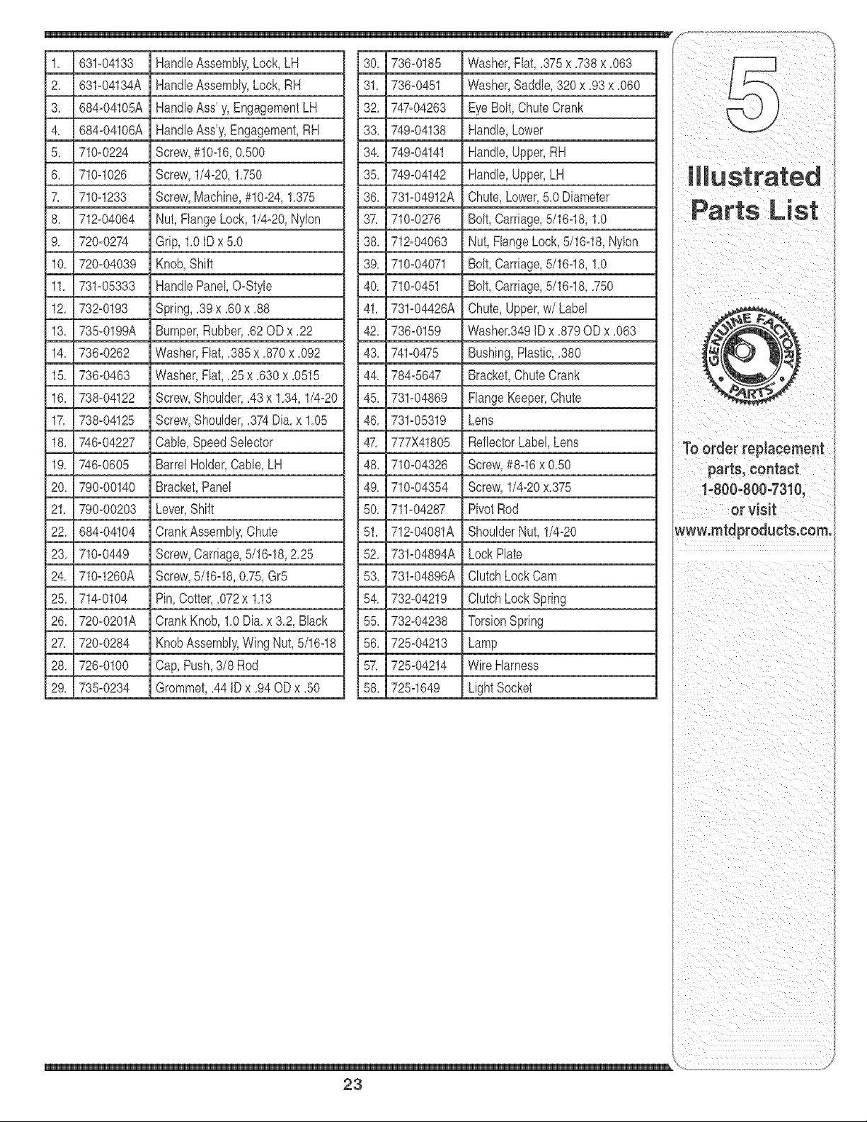
1, 631=04133 HandleAssembly,Lock, LH 30, 736=0185 Washer,Flat,,375x ,738x ,063
2, 631=04134A HandleAssembly,Lock, RH
3, 684=04105A HandleAss' y, EngagementLH
4, 684=04106A HandleAss'y,Engagement,RH
5, 710=0224 Screw,#1Od6,0,500
6, 710d026 Screw,1/4=20,1,750
7, 710q233 Screw,Machine,#10=24,1,375
8, 71b04064 Nut,FlangeLock,1/4=20,Nylon
9, 720=0274 Grip,1,0IDx5,0
10, 720=04039 Knob,Shift
11, 731=05333 HandlePanel,O=Style
12, 732=0193 Spring,,39 x ,60x ,88
13, 735=0199A Bumper,Rubber,,62 ODx ,22
14, 736=0262 Washer,Flat,,385 x ,870x ,092
15, 736=0463 Washer,Flat,,25x ,630x ,0515
16, 738=04122 Screw,Shoulder,,43 x 1,34,1/4=20
17, 738=04125 Screw,Shoulder,,374Dia,x 1,05
18, 746=04227 Cable,SpeedSelector
19, 748=0605 BarrelHolder,Cable,LH
20, 790=00140 Bracket,Panel
21, 790=00203 Lever,Shift
22, 684=04104 CrankAssembly,Chute
23, 710=0449 Screw,Carriage,5/16q8, 2,25
24, 710d260A Screw,5/16d8, 0,75,Gr5
25, 714=0104 Pin,Cotter,,072x 1,13
26, 720=0201A CrankKnob,1,0Dia, x 3,2, Black
27, 720=0284 KnobAssembly,WingNut, 5/16q8
28, 726=0100 Cap,Push,3/8 Rod
29, 735=0234 Grommet,,44 JDx ,94ODx ,50
31, 736=0451 Washer,Saddle,320 x ,93 x ,060
32, 747=04263 Eye Bolt,ChuteCrank
33, 749=04138 Handle,Lower
34, 749=04141 Handle,Upper,RH
35, 749=04142 Handle,Upper,LH
36, 731=04912A Chute,Lower,5,0Diameter
37, 710=0276 Bolt,Carriage,5/16d8, 1,0
38, 71b04063 Nut, FlangeLock,5/16d8, Nylon
39, 710=04071 Bolt,Carriage,5/16q8, 1,0
40, 710=0451 Bolt,Carriage,5/16q8, ,750
41, 731=04426A Chute,Upper,w/Label
42, 736=0159 Washer,349JDx ,879OD x ,063
43, 741=0475 Bushing,Plastic,,380
44, 784=5647 Bracket,ChuteCrank
45, 731=04869 FlangeKeeper,Chute
46, 731=05319 Lens
47, 777X41805 ReflectorLabel,Lens
48, 710=04326 Screw,#8d6 x 0,50
49, 710=04354 Screw,1/4=20x,375
50, 711=04287 PivotRod
51, 71bO4081A ShoulderNut, 1/4=20
52, 731=04894A LockPlate
53, 731=04896A ClutchLockCam
54, 73b04219 ClutchLockSpring
55, 73b04238 TorsionSpring
56, 725=04213 Lamp
57, 725=04214 WireHarness
58, 725q649 Light Socket
\
23
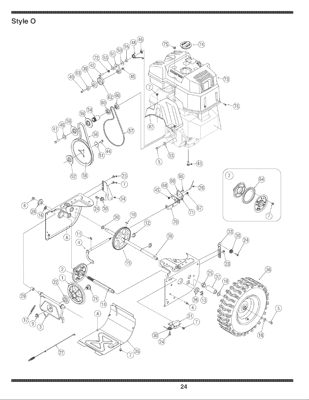
StyWe 0
@
\\
24

, _i _i i_ G i _III
1, 756-04177 Disc,FrictionWheel 39, 741-0919 Ball Bearing
2, 684-04153
3, 684-04154
4, 684-04156
5, 710-0627
6, 710-0788
7, 710-0896
8, 712-04085
9, 712-0413
10, 714-0126
11, 716-0104
12, 716-0136
13, 716-0231
14, 717-04209
15, 717-04230
16, 726-0221
17, 732-0264
18, 736-0242
19, 736-0287
20, 736-04161
21, 738-04164
22, 741-04098
23, 738-04184
24, 738-0924
25, 741-0245
26, 741_0563
27, 746-04229
28, 746_04230
29, 748_0190
30, 756_0625
31, 790-00096
32, 790_00180
33, 790_00206
34, 790-00207
35, 790_00226
36, SeeChart
37, 731-04873
38, 738-04188
FrictionWheelAssembly,5,50D
SupportBracket,FrictionWheel
ShiftAssembly,Rod
HexScrew,5/16-24,,750,Gr5
Screw,1/4-20,1,000
Screw,1/4-14x ,625
Nut,FlangeLock,3/8-18,Nylon
Nut,JamLock,5/8-18,Gr5, Nylon
Key,Hi Pro,3/16x 3/4 Dia,
E_ring,,500 Dia,
E-ring,Retaining, ,875Dia,
E-ring,,750Dia,
HexShaft,,8125,7-Tooth
Gear,80-Tooth
SpeedNut, ,500
ExtensionSpring
Washer,Bell,,340 x ,872x ,060
Washer,Flat,,793x 1,24x ,080
Washer,Flat,,75x 1,00x ,060
Pin,FrictionDisc
BallBearing,30x 55 x 13
Screw,Shoulder,,37 x ,105,1/4_20
Screw,1/4_28,,375
Bearing,RexFlangex ,75ID
Bearing,Ball, 17x 40 x 12
ClutchCable,Wheel,44,95"
ClutchCable,Auger,47,23"
Spacer,,508 IDx ,75 ODx ,68
Roller,Cable
FrontGuideBracket,AugerCable
Frame
GuideBracket,AugerCable
GuideBracket,DriveCable
Cover,Frame
WheelAssembly
Spacer,1,25x ,75x 3,0
Axle,,75x 22"
40, 710_0108 Rex Screw,1/4_20,1,25,Gr5
41, 710_0191 Rex Screw,3/8_24,1,25,Gr8
42, 710_0672 Hex Screw,5/16_24,1,25,Gr5
43, 710_0654A Screw,Seres,3/8_16,1,00
44, 710_1245B Rex Screw,5/16_24,,875,Gr8
45, 712_04064 Nut, FlangeLock, 1/4_20,Nylon
46, 726_04012 Nut, Push-on,,25 Dia,
47, 731_05353 Cover,Belt
48, 732_04308A Spring,Torsion,,850 ID x ,354
49, 736_0247 Washer,Flat,,406x 1,25x ,157
50, 736_0362 Washer,Flat,,330x 1,25x ,06
51, 736_0505 Washer,Flat,,34 x 1,50x ,150
52, 748_04053 Pulley,Adapter,,75Dia,
53, 748-04112 Spacer,Shoulder
54, 750_04303 Spacer,,875IDx 1,185OD
55, 750_04477 Spacer,,340x ,750x ,360
56, 754-04050 Belt,Auger Drive
57, 754_04088 Belt,WheelDrive
58, 756_04109 Pulley,AugerDrive,8,1x ,5
59, 756_04113 Pulley,Half,2,60D
60, 756_04179 Pulley,Half,1,50D
61, 790-00208 Idler Bracket,WheelDrive
62, 790_00230 Sleeve,BearingIdler
63, 750_04571 Spacer,Shoulder,,26 x ,79x ,538
64, 735_04054 Rubber,FrictionWheel,5,50D
65, 710_0751 Hex Screw,1/4_20,,620, Gr5
66, 732_04311 Spring,Torsion,,750ID x ,968
67, 738_04184 Screw,Shoulder,,37x ,105,1/4_20
68, 790-00156 Bracket,ShiftSpacer
69, 790-00217 PivotBracket,Speed Selector
70, 790_00218 ShiftBracket,SpeedSelector
71, 712_04063 Nut, FlangeLock,5/16_18,Nylon
72, 736-0119 Washer,Lock,5/16
73, 731_04049A EngineShroud,Troy-Bilt
74, 684_04011 Cap,SparkPlugAccess
75, 712-3004A Nut, FlangeLock,5/16-18,GR5
76, 710_04082 Screw,#10_16,,75
WheelAssembly Side WheelSize RimOnly Tire Only ValveOnly
634_04147A Left-Rand 15x 5 x 6 634_04151 734_04012 734_0255
634_04148A Right-Hand 15x 5 x 6 634_04151 734_04012 734_0255
parts, contact
t'800_800-7310,
or Visit
Wwwlmtdproducts:com:
\
25

26

27
MANUFACTURER'S LIMITED WARRANTY FOR
®
_ _ _ _ ,mSSW ,mZZZZZZ_ _
The limitedwarrantyset forthbelowis givenbyTroy-BiltLLCwithrespect
to newmerchandisepurchasedandusedin the UnitedStatesand/or its
territoriesandpossessions,andby MTDProductsLimitedwithrespectto
newmerchandisepurchasedandusedin Canadaand/or its territoriesand
possessions(eitherentityrespectively,"Troy-Bilt"),
"Troy-Bilt"warrantsthis product(excludingits normalwearparts as
describedbelow)againstdefectsin materialand workmanshipfor a period
of two(2) yearscommencingonthe dateof originalpurchaseand will, at
itsoption,repairor replace,free of charge,anypartfound to be defective
in materialsor workmanship,This limitedwarrantyshallonly applyif
thisproducthas beenoperatedand maintainedin accordancewith the
Operator'sManualfurnishedwiththe product,and hasnot beensubiectto
misuse,abuse,commercialuse,neglect,accident,impropermaintenance,
alteration,vandalism,theft,fire, water,or damagebecauseof other peril
or naturaldisaster,Damageresultingfromthe installationor useof any
part,accessoryorattachmentnotapprovedbyTroy-Biltfor use with
the product(s)coveredbythis manualwill voidyourwarrantyas to any
resultingdamage,
Normalwearpartsarewarrantedto befree fromdefectsinmaterialand
workmanshipfora periodof thirty (30)daysfromthedate of purchase,
Normalwearpartsinclude,butare notlimitedto itemssuchas: batteries,
belts,blades,bladeadapters,grass bags,rider deck wheels,seats,snow
throwerskidshoes,frictionwheels,shaveplates,augerspiral rubberand
tires,
HOWTO OBTAINSERVICE:Warrantyserviceis available,WITH
PROOFOF PURCHASE,throughyour localauthorizedservicedeabr,To
locatethe deabr inyourarea:
In the U.S.A.
CheckyourYellowPages,or contactTroy-BiltLLCat RO.Box361131,
Cleveland,Ohio 44136-0019,or call 1-866-840-6483or 1-330-558-7220,
or log on to our Web site at www.troybilt.com.
In Canada
ContactMTDProductsLimited,Kitchener,ON N2G4J1,or call 1-800-668-
1238or log on to ourWeb site at www.mtdcanada.com.
This limitedwarrantydoesnot providecoverageinthe followingcases:
a, The engineor componentparts thereof,These itemsmay
carrya separatemanufacturer'swarranty,Referto applicable
manufacturer'swarrantyfor termsandconditions,
b, Logsplitterpumps,valves,andcylindershavea separate
one-yearwarranty,
c. Routinemaintenanceitemssuch as lubricants,filters, blade
sharpening,tune-ups,brakeadiustments,clutch adiustments,
deckadiustments,and normaldeteriorationof the exteriorfinish
due to useor exposure,
d, Servicecompletedby someoneotherthan an authorizedservice
dealer,
e, Troy-Biltdoesnot extendanywarrantyfor productssold or
exportedoutsideof the UnitedStatesand/orCanada,and
their respectivepossessionsandterritories,exceptthosesold
throughTroy-Bilt'sauthorizedchannelsof exportdistribution,
f, Replacementpartsthatare notgenuineTroy-Biltparts,
g, Transportationchargesandservicecalls,
h, If Productsare usedcommercially,(Troy-Biltmayseparately
offerLimitedCommercialWarrantiesoncertainsebct products,
Askyourdealeror retailerfor detailsor contactTroy-BiltService
for moreinformation),
No implied warranty, including any implied warranty of merchant°
ability of fitness for a particular purpose, applies after the applicable
period of express written warranty above as to the parts as identi-
fied. No other express warranty, whether written or oral, except as
mentioned above, given by any person or entity, including a dealer or
retailer,with respect to any product, shall bind Troy-Bilt. During the
period of the warranty, the exclusive remedy is repair or replacement
of the product as set forth above.
The provisions as set forth in this warranty provide the sole and
exclusive remedyarising from the sale. TroyoBiltshall not be liable
for incidental or consequential loss or damage including, without
limitation, expenses incurred for substitute or replacement lawn care
services or for rental expenses to temporarily replace a warranted
product.
Somestatesdo not allowtheexclusionor limitationof incidentalor
consequentialdamages,or limitationson howlong an impliedwarranty
lasts,so the aboveexclusionsor limitationsmaynotapplyto you.
In noeventshall recoveryof any kind be greaterthanthe amountof the
purchasepriceof the productsold. Alteration of safety features of the
product shall void this warranty. Youassumethe riskandliabilityfor
loss,damage,or injuryto youand yourpropertyand/or to others and their
propertyarisingout of the misuseor inabilityto use the product.
This limitedwarrantyshall notextendto anyoneotherthanthe original
purchaseror to the personfor whomit waspurchasedas a gift.
HOWSTATELAW RELATESTO THISWARRANTY: Thislimitedwar-
rantygivesyouspecificlegal rights,and you mayalso haveother rights
whichvaryfromstateto state,
I[_tPORTANT:OwnermustpresentOriginalProofof Purchaseto obtain
warrantycoverage,
Troy-Bitt LLC, P.O. BOX 361131 CLEVELAND, OHIO 44136-0019; Phone: 1-866-840-6483, 1-330-558-7220
MTD Canada Limited - KITCHENER, ON N2G 4J1; Phone 1-800-668-1238