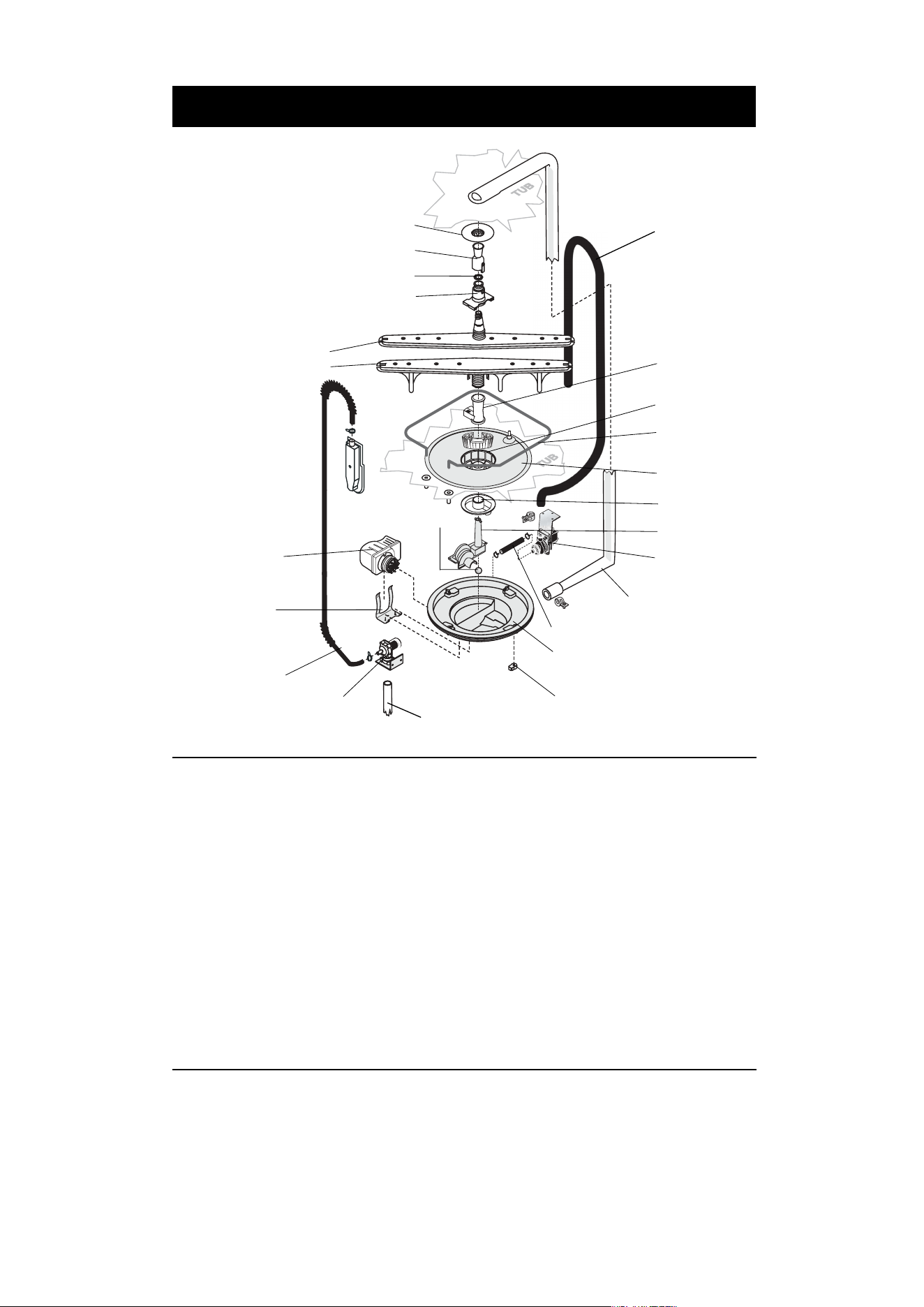
Exploded View of Wash System
900 Watt Heater
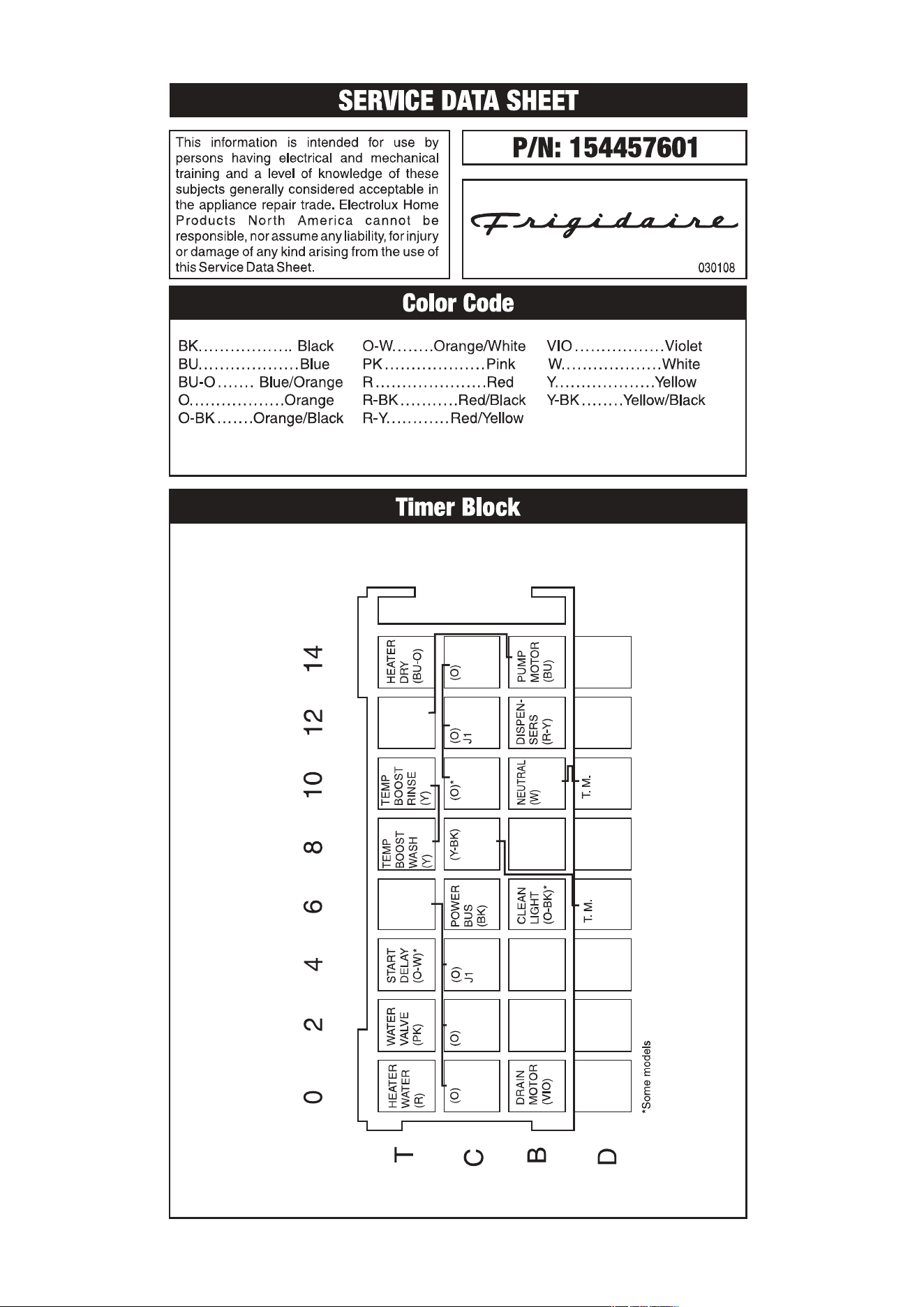
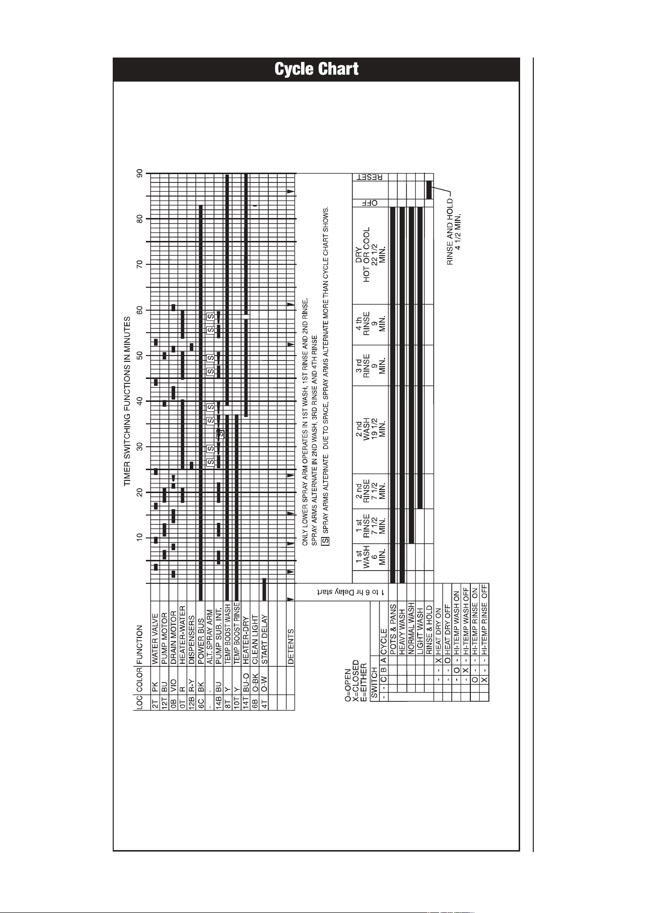
Refer to the cycle chart on the reverse side to
determine when the heater is on during the wash
cycle. The heater cycles ON and OFF for brief
periods during the drying cycle.
Voltage checks of the heater should be made
with the timer set in the main wash.
a worm gear clamp to the discharge end of the
drain pump.
The drain hose must have a loop at a
minimum
height of 32 inches
in order to insure proper
drainage.
The main pump can easily be removed by
disconnecting the upper spray arm supply tube
hose, the drain pump connector hose, the wiring
harness connections made at the circulation
motor and rotating the four sump retainers toward
the middle of the sump.
Pump Assembly
The pump assembly is driven by a synchronous
motor. Rotation is in the counterclockwise
direction at 3600 RPM. The motor drives a pump
which supplies 100 percent filtered water at a
rate to approximately 12 GPM to one spray arm
at a time. The spray arm’s operation is alternated
by small “pauses” of the motor during the wash
cycle.
Draining is accomplished by using a small
separate synchronous drain pump mounted to
the side of the sump. The drain pump is connected
to the main pump by a small rubber hose. The
drain check valve is located at the discharge end
of the drain pump. The drain hose is attached by
Nozzle
Funnel
Nut
Funnel Base
Center Spray Arm
Lower Spray Arm
Delivery Tube
Connector Hose and Clamps
Sump
Water Valve
Water Inlet Tube
Check Ball
Circulation Motor
Assembly
Motor Bracket
Incoming Water Supply
Drain Hose
(32" minimum
height)
Spray Arm
Support
Glass Trap
Heating
Element
Filter
Soil Director
Volute Cover
Drain Motor
Sump Retainers (4)
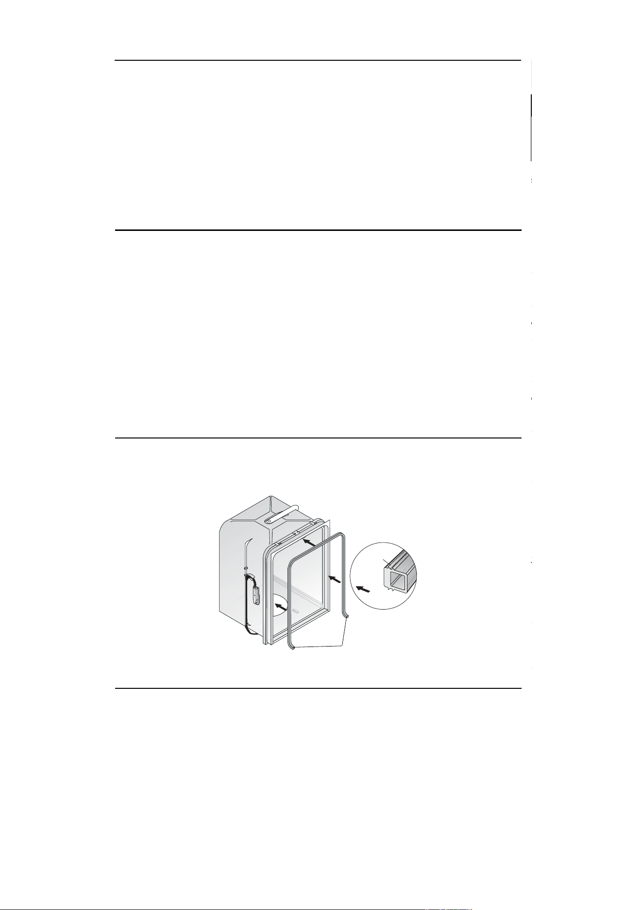
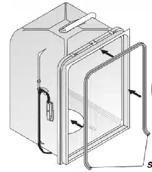
Tub and Door Seal
The door seal is pressed into the tub channel for
an interference fit. Center the gasket (marked on
back) at the tub top center and press in place
Product Specifications
Electrical
Rating .................................. 120 Volts, 60Hz
Separate Circuit..15 amp min.- 20 amp
max.
Motor (Amps) ........................................... 1.1
Heater Wattage ....................................... 900
Total Amps (load rated) ......................... 10.0
Temp Boost Wash ....................... 117°F±5°F
(47°C±3°C) [with outer door in place]
Temp Boost Rinse ................... 122°F (50°C)
Hi-Limit Thermostat ................ 200°F (93°C)
Water Supply
Suggested minimum incoming water
temperature ............................. 120°F (49°C)
Pressure (PSI) min./max. ................... 20/120
Connection (NPT) .....................................
3
/
8
"
Consumption (Normal Cycle) .......................
......... 6.0 U.S. gal., 5.0 Imp. gal., 22.7 liters
Water valve flow rate (U.S. GPM) .......... .83
Water recirculation rate (U.S. GPM)..............
.................................................... approx. 12
Water fill time ..................................... 87 sec.
Detergent and Rinse Aid Dispenser
The detergent and rinse aid dispenser is a one
piece component consisting of a molded
detergent cup and a built-in rinse aid dispenser.
The detergent cup has a spring loaded cover
and the rinse aid dispenser has a removable
cover.
Liquid rinse aid is added to the dispenser up to
the fill line indicator. The amount of rinse aid
released can be adjusted by turning the arrow
indicator from one, being the least amount, to
four, being the greatest amount.
To replace dispenser:
• shut off electricity to dishwasher,
• remove outer door panel assembly,
• disconnect wiring to the actuator,
• remove the six screws,
• remove the dispenser,
• replace and reinstall screws,
• rewire actuator.
Symptom
turned on (wait at least 90 seconds).
overload protector.
open.
Timer does not advance.
without stretching or bunching. The gasket takes
a short turn at the bottom of the tub channel
before ending at the channel end wall.
Tub
Interior
Mounting
Rib
Gasket Cross Section
Short Turn
Standard Dry Air Flow
The heated, moist air leaves the dishwasher
through the console vent causing drier air to be
drawn into the unit by way of intake vents located
at the bottom of the door. The water on the
dishes is evaporated into drier air and the venting
process continues. The heating element is turned
ON and OFF during the entire drying cycle.
Remedy
1. Replace fuse or reset breaker.
2. Repair or replace wire fasteners at
dishwasher junction box.
3. Replace timer.
4. Replace motor/impeller assembly.
5. Replace latch assembly.
6. Replace latch assembly.
7. Replace selector switch.
1. Replace motor assembly.
2. Rotate motor impeller.
1. Check voltage.
2. Replace motor/impeller assembly.
3. Clean and clear blockage.
1. Replace heater element.
2. Replace timer.
3. Repair or replace.
4. Replace thermostat.
1. Replace dispenser.
2. Replace timer.
3. Repair or replace.
4. Replace dispenser.
5. Replace dispenser.
1. Clear restrictions.
2. Replace timer.
3. Replace pump.
4. Check for blockage, clear.
5. Replace pump assembly.
1. Turn water supply on.
2. Replace water inlet fill valve.
3. Disassemble and clean screen.
4. Repair or replace.
5. Replace timer.
6. Repair or replace.
7. Clean float.
1. Replace timer.
2. Repair or replace timer.
3. Repair or adjust.
4. Replace or adjust position of
thermostat.
1. Repair to proper
32-inch minimum
height
.
2. Install air gap at counter top.
1. Instruct customer/user.
2. Instruct customer/user.
3. Instruct customer/user on proper
loading of dishes.
4. Incoming water temperature of 120°F
is required to properly dissolve
dishwashing detergents.
Trouble Shooting Tips
Check the Following
1. Fuse (blown or tripped).
2. 120 VAC supply wiring connection
faulty.
3. Timer (contacts open or defective)
4. Motor (inoperative).
5. Door switch (open contacts).
6. Door latch not making contact with
door switch.
7. Selector switch (open contacts).
1. Motor (bad bearings).
2. Motor stuck due to prolonged
non-use.
1. Improper voltage.
2. Motor windings shorted.
3. Glass or foreign items in pump.
1. Heater element (open).
2. Timer defective.
3. Wiring or terminal defective.
4. Hi-limit thermostat defective.
1. Latch mechanism defective.
2. Timer contact defective.
3. Wiring or terminal defective.
4. Broken spring(s).
5. Defective actuator.
1. Drain restricted.
2. Timer contact defective.
3. Defective drain pump.
4. Blocked impeller.
5. Open windings.
1. Water supply turned off.
2. Defective water inlet fill valve.
3. Check fill valve screen for
obstructions.
4. Defective float switch.
5. Timer contact defective.
6. Wiring defective.
7. Float stuck in “UP” position.
1. Timer motor (stalled or open.)
2. Check timer for power to timer
motor.
3. Timer shaft binding to or knob
interference with escutcheon.
4. TempBoost thermostat defective.
1. Drain hose (high) loop too low.
2. Drain line connected to a floor drain
not vented.
1. Detergent allowed to stand too long
in dispenser.
2. Dispenser wet when detergent was
added.
3. Detergent cover held closed or
blocked by large dishes.
4. Improper incoming water
temperature to properly dissolve
detergent.
5. See "Detergent cover will not
open."
Always disconnect the dishwasher from the electrical power source before adjusting or
replacing components.
Personal Injury Hazard
Symptom
Dishwasher will not operate when
turned on (wait at least 90 seconds).
Motor hums but will not start or run.
Motor trips out on internal thermal
overload protector.
Dishwasher runs but will not heat.
Detergent cover will not latch or
open.
Dishwasher will not pump out.
Dishwasher will not fill with water.
Timer does not advance.
Dishwasher water siphons out.
Detergent left in dispenser.
020822