
Owner's Manual
CRflFTSMflN
16.5 HP
ELECTRIC START
46" MOWER
AUTOMATIC
LAWN TRACTQ_t
Model No:
917.2-72021
L=Z•
• Safety
• Assembly
• Operation
• Maintenance
----*Repair Parts
CAUTION:
Read and follow all
Safety Rules and Instructions
before operating this equip-
ment.
For answers to your questions
about this product, Call:
1-800-659-5917
Sears Craftsman Help Line
5 am, 5 pm, Mon- Sat
Sears, Roebuck and Co., Hoffman Estates, IL 60179
Tum-_offblades when not mowing.
Stop engine before removing grass
catcher or unclogging chute.
Mow only in daylight or good artificial
light.
Do not operate the machine while under
the influence of alcohol or drugs.
Watch for traffic when operating near or
crossing roadways.
Use extra care when loading or unload-
ing the machine into a trailer or truck.
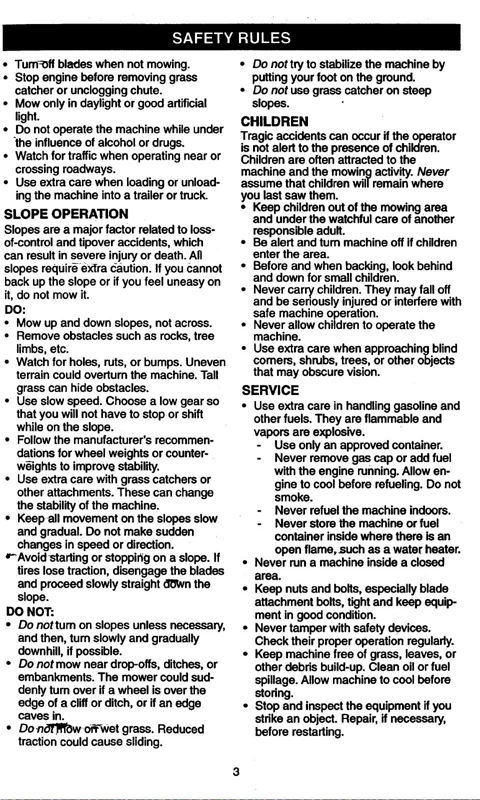
SLOPE OPERATION
Slopes are a major factor related to loss-
of-control and tipover accidents, which
can result in severe injury or death. All
slopes requir_ eXtra caution. If you Cannot
back up the slope or if you feel uneasy on
it, do not mow it.
DO:
• Mow up and down slopes, not across.
• Remove obstacles such as rocks, tree
limbs, etc.
• Watch for holes, ruts, or bumps. Uneven
terrain could overtum the machine. Tall
grass can hide obstacles.
• Use slow speed. Choose a low gear so
that you will not have to stop or shift
while on the slope.
• Follow the manufacturer's recommen-
dations for wheel weights or counter-
w_ights to improve stability.
• Use extra care with grass catchers or
other attachments. These can change
the stability of the machine.
• Keep all movement on the slopes slow
and gradual. Do not make sudden
changes in speed or direction.
_Avoidstarting or stoppidg on a slope. If
tires lose traction, disengage the blades
and proceed slowly straight o'0Wnthe
slope.
DO NOT:
• Do not tum on slopes unless necessary,
and then, turn slowly and gradually
downhill, if possible.
• Do not mow near drop,offs, ditches, or
embankments. The mower could sud-
denly turn over if a wheel is over the
edge of a cliff or ditch, or if an edge
caves in.
• Do_o3'R_worr--Wet grass. Reduced
traction could cause sliding.
• Do not try to stabilize the machine by
putting your foot on the ground.
• Do not use grass catcher on steep
slopes.
CHILDREN
Tragic accidents can occurifthe operator
is notalert to the presence of children.
Children are oftenattracted to the
machine and the mowingactivity.Never
assume that childrenwill remain where
you last saw them.
• Keep children outof the mowingarea
and underthe watchfulcare of another
responsible adult.
• Be alert and tum machine off if children
enter the area.
• Before and when backing, look behind
and down for small children.
• Never carry children. They may fall off
and be seriously injured or interfere with
safe machine operation.
• Never allow children to operate the
machine.
• Use extra care when approaching blind
comers, shrubs, trees, or other objects
that may obscure vision.
SERVICE
Use extra care in handlinggasoline and
other fuels. They are flammable and
vapors are explosive.
Use only an approvedcontainer.
Never remove gas cap oradd fuel
withthe engine running.Allow en-
gine to cool before refueling.Do not
smoke.
Never refuelthe machine indoors.
Never store the machine orfuel
container insidewhere there isan
open flame,such as a water heater.
Never run a machine insidea closed
area.
• Keep nuts and bolts, especially blade
attachment bolts, tight and keep equip,
ment in good condition.
• Never tamper with safety devices.
Check their proper operation regularly.
• Keep machine free of grass, leaves, or
other debds build-up. Clean oil or fuel
spillage. Allow machine to cool before
stodng.
• Stop and inspect the equipment if you
stdke an object. Repair, if necessary,
before restarting.
3
Never make adjustmentsor repairswith
the_qgine_running.
Grass catcher componentsare subject
to wear, damage, and deterioration,
whichcouldexpose moving partsor
allow objectsto be thrown. Frequently
check componentsand replace with
- manufacturer'srecommended parts,
when necessary.
• Be sure th6arOa is Clear of other people
before mowing. Stop machine if anyone
enters the area.
• Never carry passengers.
• Do not mow in reverse unless absolute-
ly necessary. Always look down and
behind before and while backing.
• Never carry children. They may fail off
and be seriously injured or interfere with
safe machine operation.
• Keep children out of the mowing area
and under the watchful care of another
responsible adult.
• Be alert and turn machine off if children
enter the area.
• Before and when-backing, look behind
and down for small children.
• Mower blades are sharp and can cut.
Wrap the blade(s) or wear gloves, and
use extra caution when servicing them.
• Check brake operation frequently.
Adjust and service as required.
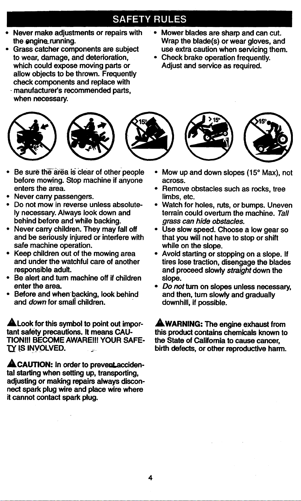
• Mow up and down slopes (15 ° Max), not
across.
• Remove obstacles such as rocks, tree
limbs, etc.
• Watch for holes, ruts, or bumps. Uneven
terrain could overtum the machine. Tall
grass can hide obstacles.
• Use slow speed. Choose a low gear so
that you will not have to stop or shift
while on the slope.
• Avoid starting or stopping on a slope. If
tires lose traction, disengage the blades
and proceed slowly straight down the
slope.
• Do not tum on slopes unless necessary,
and then, tum slowly and gradually
downhill, if possible.
• lLLookfor this symbol to point out impor-
tant safety precautions. It means CAU-
TION!!! BECOME AWAREI!! YOUR SAFE-
IS INVOLVED. _=.
ACAUTION: In orderto preveal,acciden-
tal starling when setting up, transporting,
adjustingormaking repairs always discon-
nect spark plugwire and place wire where
itcannot contactspark plug.
,AWARNING: The engine exhaust from
this product contains chemicals known to
the State of Califomia to cause cancer,
birth defects, or other reproductive harm.
4

PRODUCT SPECIFICATIONS
GASOLINE
CAPACITY
ANDTYPE.'-
OILTYPE
API-SF/SG/SH):
3.5 GALLONS
UNLEADED
REGULAR
SAE 10W-30
(above32°1)
SAE 5W-30
(below 32°1)
DIL CAPACITY: W/FILTER: 4.0 PINTS
W/O FILTER: 3.5 PINTS
SPARK PLUG: Champion RC12YC
(GAP: .040")
GROUND SPEED FORWARD: 0- 4.5
(MPH): REVERSE: 0- 2.0
TIRE PRESSURE: FRONT: 14 PSI
REAR: 10 PSI
CHARGING
SYSTEM: 15AMPS @ 3600 RPM
BA'I-I'ERY: AMP/HR: 30
MIN. CCA: 240
CASE SIZE: UlR
BLADE BOLT 27-35 FT. LBS.
TORQUE:
CONGRATULATIONS on your purchase
of a Craftsman Tractor. It has been
designed, engineered and manufactured
to give you the best possibledependability
and performance.
Shouldyou experience any problemyou
cannoteasily remedy,please contactyour
nearest Sears AuthorizedService Center.
We have competent, well-trainedtechni-
cians and the propertoolsto serviceor
repairthis tractor.
Please read and retain thismanual. The
---instructionswill enable you to assemble
and maintainyourtractor properly.Always
observethe "SAFETY RULES=_
MAINTENANCE AGREEMENT
kASears Maintenance Agreement is avail-,
able onthis product.Contact your nearest
Sears store for details.
CUSTOMER RESPONSIBILmES
• Read and observe the safety rules.
• Follow a regular schedule in maintain-
ing, caring for and using your tractor.
• Follow the instructions under =Mainte-
nance" and =Storage" sections of this
owner's manual.
,AWARNING: This tractor is equipped
with an intemal combustion engine and
should not be used on or near any unim-
proved forest-covered, brush-covered or
grass-covered land unless the engine's
exhaust system is equipped with a spark
arrester meeting applicable local or state
laws (if any). If a spark arrester is used, it
should be maintained in effective working
order by the operator.
In the state of Califomia the above is
required by law (Section 4442 of the
California Public Resources Code). Other
states may have similar laws. Federal
laws apply on federal lands. A spark
arrester for the muffler is available through
your nearest Sears Authorized Service
Center (See REPAIR PARTS section of
this manual).
5

Parts Bag contents shown full size
(1) Knob
(
(1) Washer
17/32 x 1-3/16 x 12 Gauge
(1) Shoulder
Bolt 5/16-18
(2) Washers
3/16 x 3/4 x 16 Gauge
(2) Weld
Nuts #10
(2) Screws #10 x 5/8
(2) Lock
Washers #10
(4) Retainer Springs (single loop)
(3) Retainer Spdngs (double loop)
6

Parts packed separately in carton
Seat
Video
Cassette
• Mulcher
Plate
Manual
I
Parts Bag
Steering
Wheel
m
(2) Shoulder
- Bolts
(2) Gauge Wheels
G
(2) Washers 3/8x 7/8 x 14 Gauge
Q(2) Center lock Nuts
Parts Bag. contents not shown full size
Hook (2) Keys
Assemblies
(2) rontUnk Assemblies
I=
'Slope Sheet
Steedng
wheel
Insert
Steering Sleeve
' , .i"
Stsedng Sleeve
Extension _:
7
You_newtractor has been assembledat thefactory withexceptionof thosepartsleft
unassembledfor shippingpurposes.Toensuresafeand properoperationofyour tractor
all parts and hardware you assemble mustbe tightened securely.Use the correcttools
as necessary to insureproper tightness.Review the video cassette before you begin.
TOOLS REQUIRED FOR
ASSEMBLY
" A socket wrench set will make assembly
easier. Standard wrench sizes you need
are listed below.
(1) 3/4" wrench
(2) 1/2" wrench
(1) Utility knife
(1) Pliers
(1) 314" Socket w/
drive rachet
(1) Phillips Screw-
driver
(1) Tire pressure gauge
IMPORTANT: Check for and remove any
staples in skid that may puncture tires
where tractor is to roll off skid.
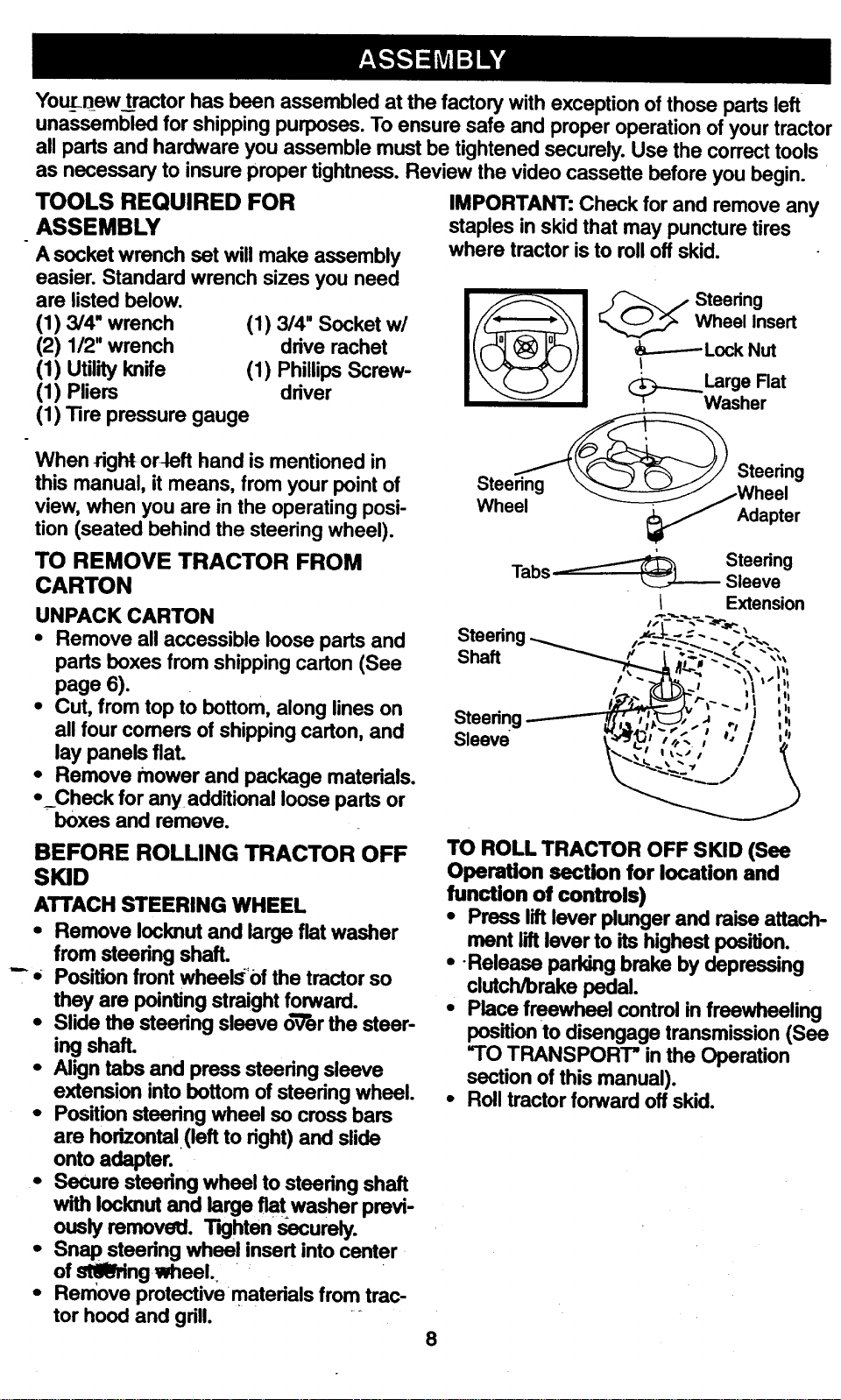
_ Wheel Insert
--..-----Lock Nut
_j..__ Large Flat
_. Washer
When right or-left hand is mentioned in
this manual, it means, from your point of
view, when you are in the operating posi-
tion (seated behind the steering wheel).
TO REMOVE TRACTOR FROM
CARTON
UNPACK CARTON
• Remove all accessible loose parts and
parts boxes from shipping carton (See
page 6).
• Cut, from top to bottom, along lines on
all four comers of shipping carton, and
lay panels flat.
• Remove mower and package materials.
• Check for anyadditional loose parts or
boxes and remove.
BEFORE ROLLING TRACTOR OFF
SKID
ATTACH STEERING WHEEL
• Remove Iocknut and large flat washer
from steedng shaft.
"" • Position front whee_'0f the tractor so
they are pointing straight forward.
• Slide the steering sleeve o-V'erthe steer-
ing shaft.
• Align tabs and press steedng sleeve
extension into bottom of steering wheel.
• Position steering wheel so cross bars
are horizontal (left to dght) and slide
onto adapter.
• Secure steedng wheel to steedng shaft
with Iocknut and large flat washer previ-
ously removetl. Tighten securely.
• Snap steedng wheel insert into center
of st,61_ng wheel.
• Remove protectivematedals from trac-
tor hood and grill.
Steering
Steering
Wheel Adapter
Tabs _ Steering
Sleeve
I Extension
I " - ,,.,_,. -- t_ I':l I
Steering------'-"TK,, ;1___-2;.-' . : ,',
s,eev / ','! ,:
\ "_._, - ..,, / \
TO ROLL TRACTOR OFF SKID (See
Operation section for location and
function of controls)
• Press liftlever plunger and raise attach-
ment liftlever to its highest position.
• -Release parking brake by depressing
clutch/brake pedal.
• Place freewheel control in freewheeling
position to disengage transmission (See
"TO TRANSPORT" in the Operation
section of this manual).
• Roll tractor forward off skid.
8
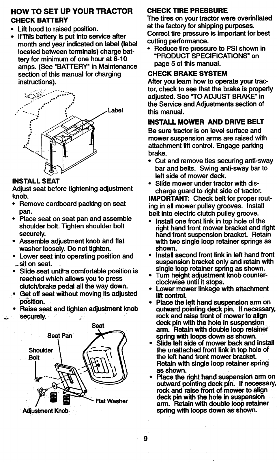
HOW TO SET UP YOUR TRACTOR
CHECK BATTERY
• Lift hoodto raisedposition.
• If-IW=sbatteryis putintoserviceafter
month andyear indicatedon label (label
locatedbetweenterminals)chargebat-
teryfor minimumof one hourat 6-10
amps.(See "BATTERY"in Maintenance
section ofthis manualfor charging
instructions).
.,'_ $==,=B •
oo $
/,
"" Label
INSTALL SEAT
Adjust seat before tightening adjustment
knob.
• Remove cardboard packing on seat
pan.
• Place seat on seat pan and assemble
shoulder bolt. Tighten shoulder bolt
securely.
• Assemble adjustment knob and flat
washer loosely. Do not tighten.
• Lower seat into operating position and
-.-siton seat.
• Slide seat untiPa comfortable position is
reached which allows you to press
clutch/brake pedal all the way down.
• Get off seat without moving its adjusted
Ix)sition.
• Raise seat and tighten adjustment knob
SeC_urely. _,.
Seat
Seat Pan
Shoulder
Bolt
Adjustment Knob
Flat Washer
CHECK TIRE PRESSURE
The tires on your tractor were ovednflated
at the factory for shipping purposes.
Correct tire pressure is important for best
cutting performance.
• Reduce tire pressure to PSI shown in
"PRODUCT SPECIFICATIONS" on
page 5 of this manual.
CHECK BRAKE SYSTEM
After you leam how to operate your trac-
tor, check to see that the brake is properly
adjusted. See =TO ADJUST BRAKE" in
the Service and Adjustments section of
this manual.
INSTALL MOWER AND DRIVE BELT
Be sure tractor is on level surface and
mower suspension arms are raised with
attachment lift control. Engage parking
brake.
• Cut and remove ties securing anti-sway
bar and belts. Swing anti-sway bar to
left side of mower deck.
• Slide mower under tractor with dis-
charge guard to right side of tractor.
IMPORTANT: Check belt for proper rout-
ing in all mower pulley grooves. Install
belt into electric clutch pulley groove.
• Install one front link in top hole of the
right hand front mower bracket and right
hand front suspension bracket. Retain
with two single loop retainer springs as
shown.
• Install second front link in left hand front
suspension bracket only and retain with
single loop retainer spnng as shown.
• Tum height adjustment knob counter-
clockwise until it stops.
• Lower mower linkage with attachment
lift control.
• Place the left hand suspension arm on
outward pointing deck pin. If necessary,
rock and raise front of mower to align
deck pin with the hole in suspension
arm. Retain with double loop retainer
spdng with loops down as shown.
• Slide left side of mower back and install
the unattached front link in top hole of
the left hand front mower bracket.
Retain with single loop retainer spring
as shown.
• Place the righthand suspensionarm on
outward pointing deck pin. if necess.,ary,
rockand raise front of mower toauign
deck pin with the hole in suspension
arm. Retain with double loop retainer
spring with loops down as shown.
9
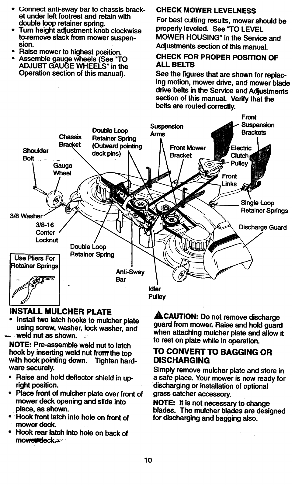
• Gonnect anti-sway bar to chassis brack-
et under leftfootrestand retainwith
double loop retainerspring.
•Tum heightadjustment knobclockwise
t_remove slack from mower suspen-
sion.
• Raise mower to highest position.
• Assemble gauge wheels (See "TO
ADJUST GAUGE WHEELS = in the
Operation section of this manual).
Double Loop
Chassis Retainer Spring
Bracket (Outward pointing
Shoulder deck pins)
Boat ÷ --- --_ .-- --
Gauge
Wheel
CHECK MOWER LEVELNESS
For best cutting results, mower should be
properly leveled. See "TO LEVEL
MOWER HOUSING" in the Service and
Adjustments section of this manual.
CHECK FOR PROPER PosmoN OF
ALL BELTS
See the figures that are shown for replac-
ing motion, mower drive, and mower blade
drive belts in the Service and Adjustments
section of this manual. Vedfy that the
belts are routed correctly.
Front
sus_ suspen_on
Arms Brackets
Front Mower Electric
Bracket Clutch
Front
3/8 Washer
3/8-16
Center
Locknut
Use Pliers For
Retainer Springs
Double Loop
Retainer Spring
Anti-Sway
Bar
INSTALL MULCHER PLATE
• Install two latch hooks to mulcher plate
using screw, washer, lock washer, and
.... weld nut as shown. _:-
NOTE: Pre-assemble weld nut to latch
hook byinserting weld nut from'the top
with hook pointing down. Tighten hard-
ware securely.
• Raise and hold deflector shield in up-
right position.
• Place front of mulcher plate over front of
mower deck opening and slide into
•place, as shown.
• _Hook front latch into hole on front of
mower deck. _
• Hook rear latch into hole on back of
mo__-
Single Loop
Retainer Springs
Discharge Guard
Idler
Pulley
ACAUTION: Do not remove discharge
guard from mower. Raise and hold guard
when attaching mulcher plate and allow it
to rest on plate while in operation.
TO CONVERT TO BAGGING OR
DISCHARGING
Simply remove mulcher plate and store in
a safe place. Your mower is now ready for
discharging or installation of optional
grass catcher accessory.
NOTE: It is not necessary to change
blades. The mulcher blades are designed
for discharging and bagging also.
10
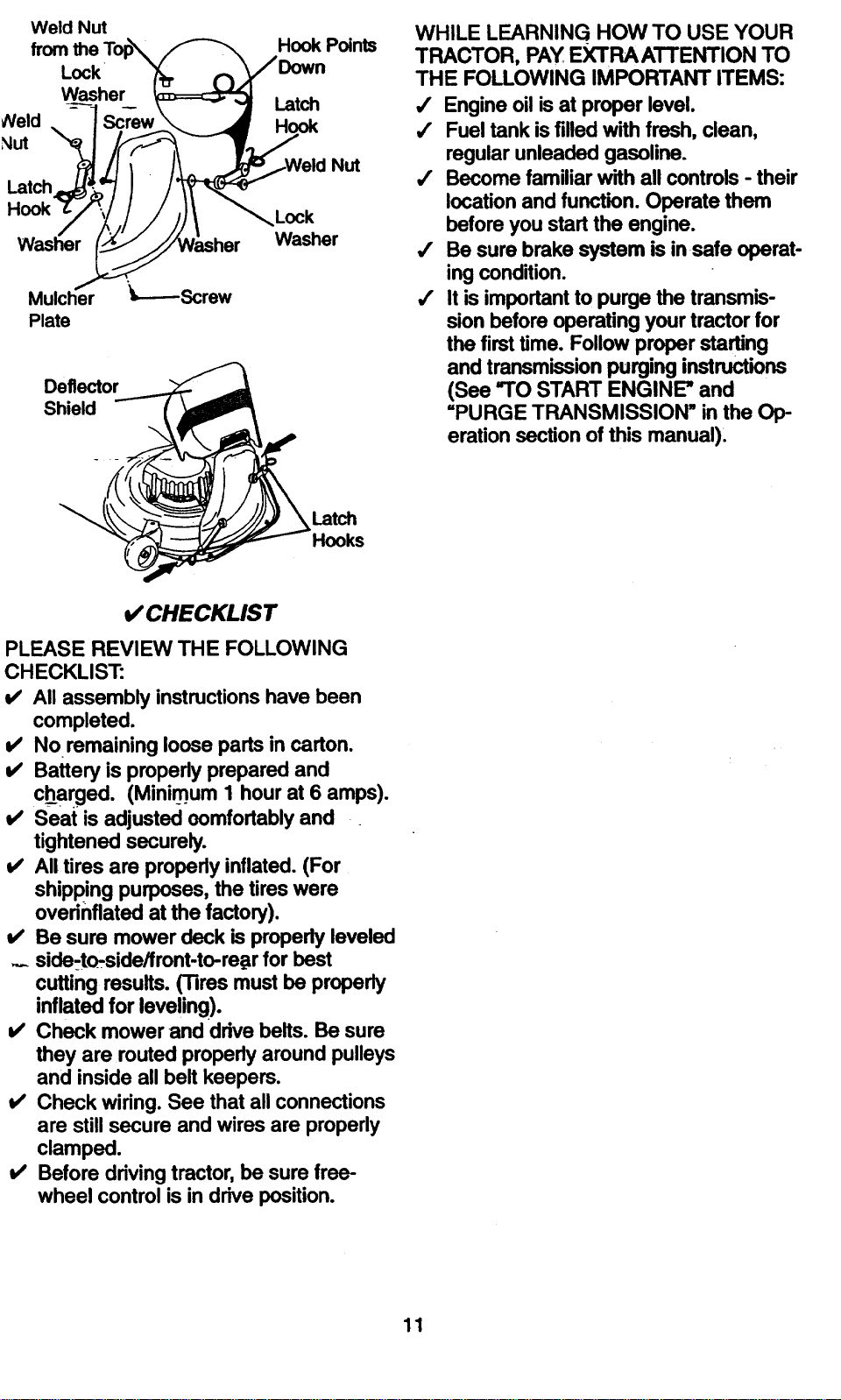
Weld Nut
from the Top_
Lock
Washer
Neld Screw
Nut
Mulcher
Plate
Deflector
Shield
Hook Points
Latch
Hook
Nut
Lock
Washer
WHILE LEARNING HOW TO USE YOUR
TRACTOR, PAY EXTRA ATTENTION TO
THE FOLLOWING IMPORTANT ITEMS:
,/ Engine oil is at proper level.
,/ Fuel tank is filled with fresh, clean,
regular unleaded gasoline.
,/ Become familiar with all controls - their
location and function. Operate them
before you start the engine.
,/ Be sure brake system is insafe operat-
ing condition.
,/ It is important to purge the transmis-
sion before operating your tractor for
the first time. Follow proper starting
and transmission purging instructions
(See "TO START ENGINE" and
=PURGE TRANSMISSION" in the Op-
eration section of this manual).
Latch
Hooks
I/CHECKLIST
PLEASE REVIEW THE FOLLOWING
CHECKLIST:
V' All assembly instructionshave been
completed.
v' No remaining loose partsin carton.
v' Battery is properlyprepared and
charged. (Minimum 1 hourat 6 amps).
v' Seat is adjusted ocmfortably and
tightened securely.
v' All tires are properlyinflated.(For
shippingpurposes, the tireswere
overinflatedat the factory).
i," Be sure mower deck is propedyleveled
... side-t_side/front-to-re_r for best
cutting results.(Tires mustbe properly
inflatedfor leveling).
v' Check mower and drive belts. Be sure
they are routed properlyaround pulleys
and inside all belt keepers.
v' Check wiring.See that all connections
are still secure and wires are properly
clamped.
v' Before drivingtractor,be sure free-
wheel control is in driveposition.
11
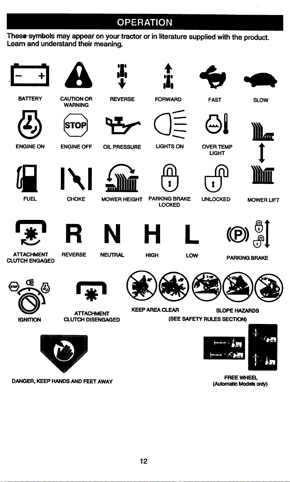
These-symbolsmay appearon your tractor or in literature supplied with the product.
Leam and understand their meaning.
BATTERY CAUTION OR REVERSE FORWARD FAST SLOW
WARNING
ENGINE ON ENGINE OFF OIL PRESSURE LIGHTS ON OVER TEMP
LIGHT
I
k
FUEL CHOKE MOWER HEIGHT PARKING BRAKE UNLOCKED MOWER LIFT
LOCKED
ATTACHMENT REVERSE
CLUTCH ENGAGED
N H L c®) I
NEUTRAL HIGH LOW
PARKING BRAKE
IGNmON
ATTACHMENT
CLUTCH DISENGAGED
KEEPAREACLEAR SLOPEHAZARDS
(SEE SAFETYRULESSECTION)
DANGER, KEEP HANDS AND FEET AWAY
FREE WHEEL
(AutomaticModels only)
12
KNOW YOUR TRACTOR
READ THIS OWNER'S MANUAL AND SAFETY RULES BEFORE OPERATING YOUR
TRACTOR-
Compare the illustrations with your tractor to familiarize yourself with the locations of
various controls and adjustments. Save this manual for future reference.
Throttle/Choke
Control
Clutch/Brake
Control_
Ignition
Switch
Light Switch
Position
Attachment
Clutch Switch
Lift Lever
Plunger
Height
Adjustment
Knob
Freewheel
Control
Attachment
Lift Lever
Brake
Motion
Control Lever
Speed
2MPH
1MPH
Our tractorsconformto the safety standardsof theAmerican
National Standards Institute.
ATTACHMENT CLUTCH SWITCH: Used
to engage the mower blades, e_,other at-
tachments mounted to your tractor.
LIGHT SWITCH: Tums the headlights on
and off.
THROTTLE/CHOKE CONTROL: Used to
control engine speed.
CLUTCH/BRAKE PEDAL: Used for
declutching and braking the tractor and
starting the engine.
FREEWHEEL CONTROL: Disengages
transmission for pushing or slowly towing
the _ae_l_wi -tb_tbeengine off.
HEIGHT'ADJUSTMENT KNOB: Used to
adjust the mower cutting height.
MOTION CONTROL LEVER: Selects the
speed and direction of the tractor.
ATTACHMENT LIFT LEVER: Used to
raise and lower the mower deck or other
attachments mounted to your tractor.
LIFT LEVER PLUNGER: Used to release
attachment lift lever when changing its
position.
IGNITION SWITCH: Used for starting and
stopping the engine.
AMMETER: Indicates battery charging (+)
ordischarging (-).
PARKING BRAKE: Locks clutch/brake
into the brake position.
13
The operationof any tractorcan result in foreignobjectsthrown into the
yes, whichcan result in severe eye damage.Alwayswear safety glasses
reye shields while operating your tractor or performing any adjustments or
repaers. We recommend a wide vision safety mask over spectacles, or stan-
dard safety glasses.
HOW TO USE YOUR TRACTOR
Yourtractoris equippedwith an operator
presence sensingswitch.When engine is
running,any attempt by the operator to
leave the seat withoutfirst settingthe
parking brake will shutoffthe engine.
TO SET PARKING BRAKE
• Depress clutch/brake pedal into full
=BRAKE" position and hold.
• Place parking brake lever in =EN-
GAGED" position and release pressure
from clutch/brake-pedal. Pedal should
remain in =BRAKE" position. Make sure
parking brake will hold tractor secure.
Throttle/ Push-In to Attachment Clutch
Choke =Disen< Switch Pull Out To
=Engage"
=Brake"
"Engaged"Pos_on
Pedal =Ddve" =Disengaged"
Position Position
STOPPING
=MOWER .BLADES -
.z:.
• To stop mower blades, move attach-
ment clutch switch to "DIS_AGED"
position.
GROUND DRIVE -
• To stop grounddrive, depress
clutch/brake pedal intofull =BRAKE"
position.
• Move motioncontrollever to neutral (N)
position.
IMPORTANT: The motioncontrollever
does not retum to neutral (N) position
when the clutch/brakepedal is depressed.
ENG1NE_. •-_-=_"
• Move throttle control to slow position.
NOTE: Failureto move throttlecontrolto
slow positionand allowingengine to idle
before stoppingmay cause engine to
=backfire".
•Tum ignition key to =OFF" position and
remove key. Always remove key when
leaving tractor to prevent unauthorized
use.
• Never use choke to stop engine.
IMPORTANT: Leaving the ignition switch
in any position other than =OFF" will cause
the battery to be discharged, (dead).
NOTE: Under certain conditions when
tractor is standing idle with the engine run-
ning, hot engine exhaust gases may
cause "browning" of grass. To eliminate
this possibility, always stop engine when
stopping tractor on grass areas.
A, CAUTION: Always stop tractor com-
pletely, as described above, before leaving
the operator's position; to empty grass
catcher, etc.
THROTTLE CONTROL
Always operate engine at full throttle.
• Operating engine at less than full throt-
tle reduces the battery charging rate.
• Full throttle offers the best bagging and
mower performance.
TO MOVE FORWARD AND BACKWARD
The direction and speed of movement is
controlled by the motion control lever.
• Start tractor with motion control lever in
neutral (N) position.
• Release parkin_ brake and clutch/brake
pedal.
• Slowly move motion control lever to
desired position.
NOTE: The effort to move the motion con-
trol lever will reduce after the first few
hours of use. This is normal.
TO ADJUST MOWER CUTTING HEIGHT
The cutting height is controlled by tuming
the height adjustment knob in desired
direction.
• Tum knob clockwise ((_) to raise cutting
height.
• Turn knob counterclockwise (,b) to
lower cutting height. "
The cutting height range is approximately
1-1/2" to 4". The heights are measured
from the ground to the blade tip with the
14
proximateand mayvary dependingupon
soilconditions, heightof grass andtypes
of grass being mowed.
• The average lawn should be cut to
ap-pr-oxir_ately2-1/2 inches during the
cool season and to over 3 inches during
hot months. For healthier and better
looking lawns, mow often and after
moderate growth.
• For best cutting performance, grass
over 6 inches in height should be
mowed twice. Make the first cut rela-
tively high; the second to desired
height.
TO ADJUST GAUGE WHEELS
Gauge wheels are properly adjusted
when they are slightly off the ground when
mower is at the desired cuffing height in
operating position. Gauge wheels then
keep the deck in proper position to help
prevents-c_rpi_g in-most terrain (_ondi-
tions.
• Adjust gauge wheels with tractor on a
flat level surface.
• Adjust mower to desired cutting height
(See =TO ADJUST MOWER CUTTING
HEIGHT" in the Operation section of
this manual).
• With mower in desired height of cut po-
sition, gauge wheels should be assem-
bled so they are slightly off the ground.
Install gauge wheel in appropriate hole
with shoulder bolt, 318 washer, and 3/8-
16 Iocknut and tighten securely.
• Repeat for opposite side installing
_gauge wheel insame adjustment hole.
Mounting ,,
Bracket
3/8-16
Locknut
3/SWasher
Shoulder Bolt
Gaug'_"Wheel
TO OPERATE MOWER
Your tractor is equipped with an operator
presence sensing switch. Any attempt by
the operator to leave the seat with the
engine running and the attachment clutch
engaged will shut off the engine.
• Select desired height of cut.
• Lower mower with attachment liftcon-
trol. __
- St_wew=blades by engaging attach-
ment' clutch control.
g_ge attachment clutch control.
AUTION: Do not operate the
Attachment Clutch
Switch Pull Out To
"Engage"
mower without either the entire grass
catcher, on mowers so equipped, or the
discharge guard in place.
Attachment Lift Lever
High PosiJJon
Push inTo
"Disengage"
Discharge
Guard
TO OPERATE ON HILLS
ACAUTION: Do not drive up or down
hills with slopes greater than 15° and do
not drive across any slope. Use the slope
guide provided at the back of this manual.
• Choose the slowest speed before start-
ing up or down hills.
• Avoid stopping or changing speed on
hills.
• If slowing is necessary, move throttle
control lever to slower position.
• If stopping is absolutely necessary,
push clutch/brake pedal quickly to brake
position and engage parking brake.
• Move motion control lever to neutral (N)
position.
IMPORTANT: The motion control lever
does not retum to neutral (N) position
when the clutch/brake pedal is depressed.
• To restart movement, slowly release
parking brake and clutch/brake pedal.
• Slowly move motion control lever to
slowest setting.
• Make all turns slowly.
TO TRANSPORT
When pushingor towingyour tractor,be
sure to disengagetransmissionby placing
freewheel controlin freewheeling position.
Freewheel controlis locatedat the rear
drawbar of tractor.
• Raise attachment liftto highestposition
withattachment liftcontrol.
• Pullfreewheel controlknobout and hold
in position by insertingretainerspring
intoforward holeof controlrod.
• Do not'pushor towtractor at morethan
two (2) MPH.
15
• IO reengage transmission, reverse
above procedure. "-
NOTE: To protect hood from damage when
transporting your tractor on a truck or a
trai[_7,_,besure hood is closed and secured
to tractor. Use an appropriate means of
tying hood to tractor (rope, cord, etc.).
TOWING CARTS AND OTHER ATTACH-
MENTS
Tow only the attachments that are recom-
mended by-and comply with specifications
of the manufacturer of your tractor. Use
common sense when towing. Too heavy of
a load, while on a slope, is dangerous.
Tires can lose traction with the ground and
cause you to lose control of your tractor.
BEFORE STARTING THE ENGINE
CHECK ENGINE OIL LEVEL
• The engine in your tractor has been
shipped, from the factory, already filled
with summer weight oil.
• Check engine oil with tractor on level
ground.
• Unthread and remove oil filicap/dip-
stick; wipe oil off. Reinsert the dipstick
into the tube and rest oil fill cap on the
-tube. Do not thread the cap onto the
tube. Remove and read oil level. If nec-
essary, add oil until =FULL" mark on
dipstick is reached. Do not overfill.
• For cold weather operation you should
change oil for easier starting (See =OIL
VISCOSITY CHART" in the Customer
Responsibilitiessectionof this manual).
o To change engine oil,-:seethe Customer
Responsibilitiessection in thismanual.
ADD GASOLINE
• Fill fuel tank. Use fresh, clean, regular
unleaded gasoline with a minimum of 87
octane. (Use of leaded gasoline will
increase carbon and lead oxide
deposits and reduce valve life). Do not
mix oil with gasoline. Purchase fuel in
quantities that can be used within 30
days to assure fuel freshness.
IMPORTANT: When operating in tempera-
tures bel_ow 32°F(0°C), use fresh, clean
winter g_'_e g_o|ine to help insUre good
cold weather starting.
16
_WARNING: Experience indicatesthat
alcoholblended fuels (called gasoholor
usingethanol ormethanol) can attract
moisturewhichleads to separation and
formation of acidsduringstorage. Acidic
gas can damage the fuel system of an
engine while instorage. To avoid engine
problems, the fuel system shouldbe emp-
tied before storage of 30 days or longer.
Drainthe gas tank, startthe engine and let
it run untilthe fuel linesand carburetorare
empty. Use fresh fuel next season. See
Storage Instructionsfor additional informa-
tion. Never use engine or carburetor
cleaner productsinthe fuel tank or perma-
nentdamage may occur.
_CAUT!ON: Fillto bottom of gas tank
filler neck. Do notoverfill.Wipe off any
spilledoil orfuel. Do notstore, spill or use
gasoline near an open flame.
TO START ENGINE
When startingthe engine for the first time
or ifthe engine has run out of fuel, itwill
take extra crankingtime to move fuel from
the tank to the engine.
• Be sure freewheel controlisin the
transmission engaged position.
• Sit on seat in operating position,
depress clutch/brake pedal and set
parkingbrake.
• Placemotion controllever in neutral (N)
position.
• Move attachment clutchto =DISEN-
GAGED" position.
• Move throttlecontrol to choke position.
NOTE: Beforestarting,read the warm and
cold startingproceduresbelow.
• Insertkey intoignitionand turn key
clockwiseto =START"positionand
release key as soon as engine starts.
Do not runstartercontinuouslyfor more
thanfifteen s.econdsper minute.If the
engine does notstart after several
attempts,move throttlecontrolto fast
position,wait a few minutesand try
again. If engine stilldoes notstart,
move the throttlecontrol back to the
choke positionand retry.
WARM WEATHER STARTING (50° F and
above)
• When engine starts,move the throttle
controlto the fast position.
• The attachmentsand ground drivecan
nowbe used, If theenginedoes not
acceptthe load, restartthe engine and
allow itto.warm upfor one minute using
the choke as described above.
UULU VVI"AI HI-FI _ IAI'I I IN(_ (, ,,_Uv F ana
below)
• When engine starts, allow engine to run
with the throttle control in the choke
positiop_until the engine runs roughly,
then move throttle control to fast posi-
tion. This may require an engine warm-
up period from several seconds to sev-
eral minutes, depending on the temper-
ature.
AUOTMATIC TRANSMISSION WARM UP
• Before driving the unit in cold weather,
the transmission should be warmed up
as follows:
• Be sure the tractor is on level ground.
• Place the motion control lever in neutral.
Release the parking brake and let the
clutch/brake slowly retum to operating
position.
• Allow one minute for transmission to
warmup: This can be done during the
engine warm up period.
• The attachments can also be used dur-
ing the engine warm-up period after the
transmission has been warmed up.
NOTE: At a high altitude (above 3000
feet) or in cold temperatures (below 32 F)
the carburetor fuel mixture may need to be
adjusted for best engine performance.
See =TO ADJUST CARBURETOR" in the
Service and Adjustments section of this
manual.
PURGE TRANSMISSION
,ACAUTION: Never engage or disen-
gage freewheel lever while the engine is
rGnning. °_
To ensure proper operationand perfor-
mance, it is recommended that the trans-
mission be purgedbefore operatingtractor
for the first time. This procedure will
remove any trapped air inside the trans-
missionwhichmay have developed during
shippingof your tractor.'
IMI_OHTANT: _Srlould your transmission
require removal for service or replace-
ment, it should be purged after reinstalla-
tion before operating the tractor.
• Place tractor safely on level surface with
engine off and parking brake set.
• Disengage transmission by placing free-
wheel control in freewheeling position
(See =TO TRANSPORT" in this section
of manual).
• Sitting in the tractor seat, start engine.
After the engine is running, move throt-
tle control to slow position. With motion
control lever in neutral (N) position,
slowly disengage clutch/brake pedal.
• Move motion control lever to full forward
position and hold for five (5) seconds.
Move lever to full reverse position and
hold for five (5) seconds. Repeat this
procedure three (3) times.
NOTE: During this procedure there will be
no movement of drive wheels. The air is
being removed from hydraulic drive sys-
tem.
• Move motion control lever to neutral (N)
position. Shut off engine and set parking
brake.
• Engage transmission by placing free-
wheel control in driving position (See
=TO TRANSPORT" in this section of
manual).
• Sitting in the tractor seat, start engine.
After the engine is running, move throt-
tle control to half (1/2) speed. With
motion control lever in neutral IN) posi-
tion, slowly disengage clutch/brake
pedal.
• Slowly move motion control lever for-
ward; after the tractor moves approxi-
mately five (5) feet, slowly move motion
control lever to reverse position. After
the tractor moves approximately five (5)
feet retum the motion control lever to
the neutral (N) position. Repeat this pro-
cedure with the motion control lever
three (3) times.
• Your tractor is now purged and ready for
normal operation.
17
MOWING TIPS
• Tirechainscannot beusedwhenthe
mower housingis attachedto tractor.
• Mower should be properly leveled for
best mowing performance. See "TO
LEVEL MOWER HOUSING" in the
Service and Adjustments section of this
manual.
• The left hand side of mower should be
used for trimming.
• Drive so that clippings are discharged
onto the area that has been cut. Have
the cut area to the right of the tractor.
This will result in a more even distribu-
lion of clippings and more uniform cut-
ling.
• When mowing large areas, start by turn-
ing to the right so that clippings will dis-
charge away from shrubs, fences, drive-
ways, et_. After one or two rour_ds,mow
in the opposite direction making left
hand turns until finished.
• If grass is extremely tall, it should be
mowed twice to reduce load and possi-
ble fire hazard from dried clippings.
Make first cut relatively high; the second
to the desired height.
• Do not mow grass when it is wet. Wet
grass will plug mower and leave unde-
sirable clumps. Allow grass to dry
before mowing.
• Always operate engine at full throttle
when mowing to assure better mowing
performance and proper discharge of
material. Regulate ground speed by se-
lecting a low enough gear to give the
mower the best cutting performance as
well as the quality of cut desired.
• When operating attachments, select a
ground speed that will suit the terrain
and give best performance of the at-
tachment being used.='.
MULCHING MOWING TIPS
IMPORTANT: For best performance, keep
mower housing free of built-up grass and
trash. Clean after each use.
• The special mulching blade will recur
the grass clippings many times and
reduce them in size so that as they fall
onto the lawn they will disperse into the
grass and not be noticed. Also, the
mulched grass will biodegrade quickly
to provide nutrients for the lawn. Always
mulch with your highest engine (blade)
speed as this will provide the best recut-
ting action of the blades.
• Avoid cutting your lawn when it is wet.
Wet grass tends to form clumps and
interferes w'dhthe mulching action. The
best lime to mow your lawn is the early
aftemoon. At this lime the grass has
dried and the newly cut area will not be
exposed to the direct sun.
• For best results, adjust the mower cut-
ting height so that the mower cuts off
only the top one-third of the grass
blades. For extremely heavy mulching,
reduce your width of cut on each pass
and mow slowly.
• Certain types of grass and grass condi-
tions may require that an area be
mulched a second time to completely
hide the clippings. When doing a sec-
ond cut, mow across or perpendicular to
the first cut path.
• Change your cutting pattern from week
to week. Mow north to south one week
then change to east to west the next
week. This will help prevent matting and
graining of the lawn.
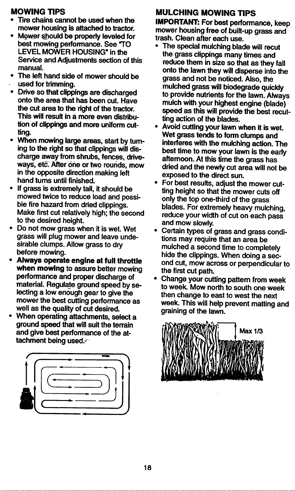
, ,." n Max 1/3
18
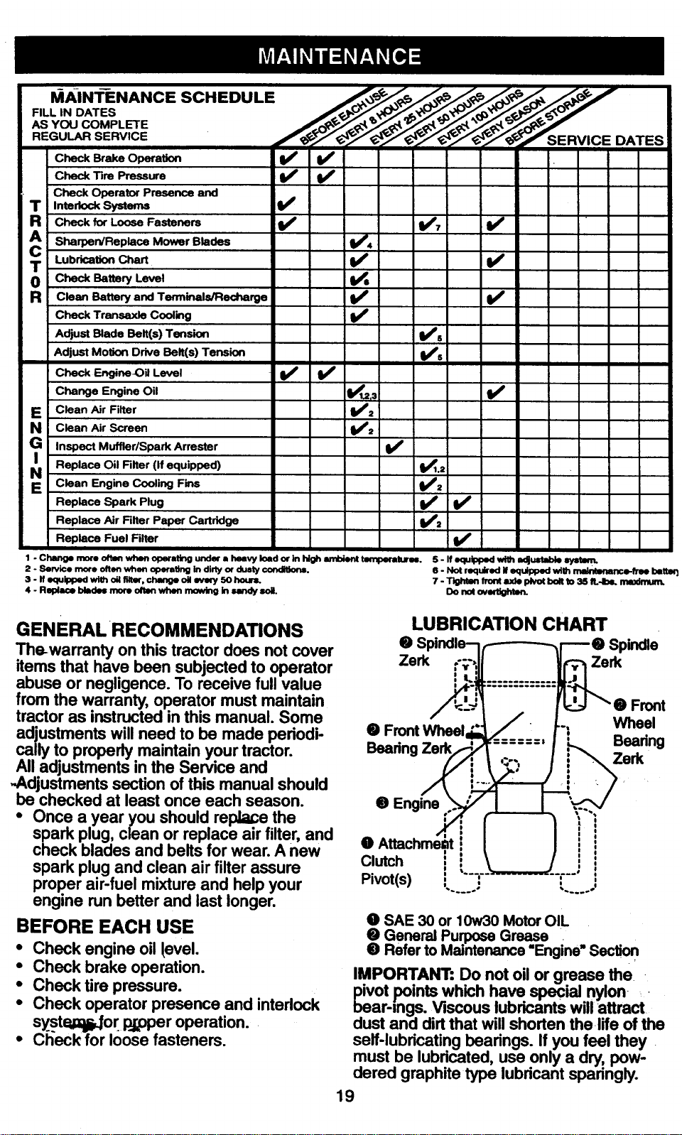
I_AiNTENANCE SCHEDULE . ,,_/._//__ _/"_,,___._"
AS YOU COMPLETE
checkB,_e op_a_on V' t/
Check Tire Pressure _ I1_
Check Operator Presence and
T IntedockSystem= !_
Check for Loose Fasteners V'
cA Sharpen/Replace Mower Blades
T Lubrication Chart
0 Check Battery Level
R clean Battery and Terminals/Recharge
Check Transaxle Cooling
Adjust Blade Belt(s) Tension
Adjust Motion Drive Belt(s) Tension
checkF_,._neO,Level V' V'
Change Engine Oil
E Clean Air Filter
N Clean Air Screen
e Inspect Muffler/Spark Arrester
Replace Oil Filter (If equipped)
NE Clean Engine Cooling Fins
Replace Spark Plug
Replace Air Filter Paper Cartridge
Replace Fuel Filter
V', v'
V',
v' v'
v',
v' v'
v'
v',
V'_., V'
V',
I/,
V'
V',
V" V'
V',
V'
1 - Change more often when operRting undm" a heavy load or ln high ambient tmnperatuT_. 5-ffequlppedwithadjustablelystmm.
2 - Sendce more often when operating in dkty or dusty co.Ink)hi. 6 - Not required If equipped wilh _rlce-free bettm3
3 - If equipped wire oil rdter, change oil eve_ 50 bourn. 7 - Tk;hten front a.,de pivot bon to 3S IL4bL mmdnun.
4 - Replace blades more orion when mowing In sandy soil. Do not ovmbghton.
GENERAL RECOMMENDATIONS
The-warranty on thistractordoes notcover
items that have been subjectedto operator
abuse or negligence.To receive full value
from the warranty, operator must maintain
tractoras instructedinthis manual. Some
adjustmentswill need to be made periodi-
callyto properlymaintain yourtractor.
Alladjustments in the Service and
-Adjustmentssection of this manual should
be checked at leastonce each season.
• Once a year you shouldreplace the
spark plug,clean or replace air filter,and
check blades and belts for wear.A new O
spark plugand clean air filterassure Clutch
properair-fuel mixture and help your Pivot(s)
engine run betterand last longer.
LUBRICATION CHART
• Spindle
Zerk Zerk
BEFORE EACH USE
• Check engine oil level.
• Check brake operation.
• Check tire pressure.
• Check operator presence and interlock
syst_or l_j_per operation.
• Ch'eck for I()ose fasteners.
• Front Wheel
Beadng
• Engine
Front
Wheel
Beadng
Zerk
O SAE 30 or 10w30 Motor OIL
O General Purpose Grease . "
@ Refer to Maintenance "Engine" Sectio n
IMPORTANT: Do not oil or grease the.
ivet points which have special nylon _
ear-rags. Viscous lubricants will attract
dust and dirt that will shorten the life of the
self-lubricating bearings. If you feel they
must be lubricated, use only a dry, pow-
dered graphite type lubricant sparingly.
19
TRACTOR
Alwaysobservesafetyruleswhenper-
forrningany maintenance.
BRAKE-OPERATION
Iftractor requiresmorethan six (6)feet
stopping distanceat highspeedin highest
gear,then brakemustbe adjusted.(See
=TO ADJUST BRAKE" in the Service and
Adjustments section of this manual).
TIRES
• Maintain proper air pressure in all tires
(See =PRODUCT SPECIFICATIONS"
on page 3 of this manual).
• Keep tires free of gasoline, oil, or insect
control chemicals which can harm rub-
ber.
• Avoid stumps, stones, deep ruts, sharp
objects and other hazards that may
cause tire damage.
NOTE: To _;e-aitire punctures and prevent
flat tires due to slow leaks, tire sealant
may be purchased from your local parts
dealer. Tire sealant also prevents tire dry
rot and corrosion.
OPERATOR PRESENCE SYSTEM
Be sure that operator presence and inter-
lock systems are working properly. Ifyour
tractor does not function as described
below, repair the problem immediately.
• The engine should not start unless the
clutch/brake pedal is fully depressed
and attachment clutch control is in the
disengaged position.
• When the engine is running,any
attempt by the operatortoleave the
s_-atwithoutfirstsettingthe parking
brake shouldshutoffthe engine.
• When the engine is running and the
attachment clutch is engaged, any
attempt by the operator to leave the
seat should shut off the engine.
• The attachment clutch should never
_operate unless the operator is in the
seat.
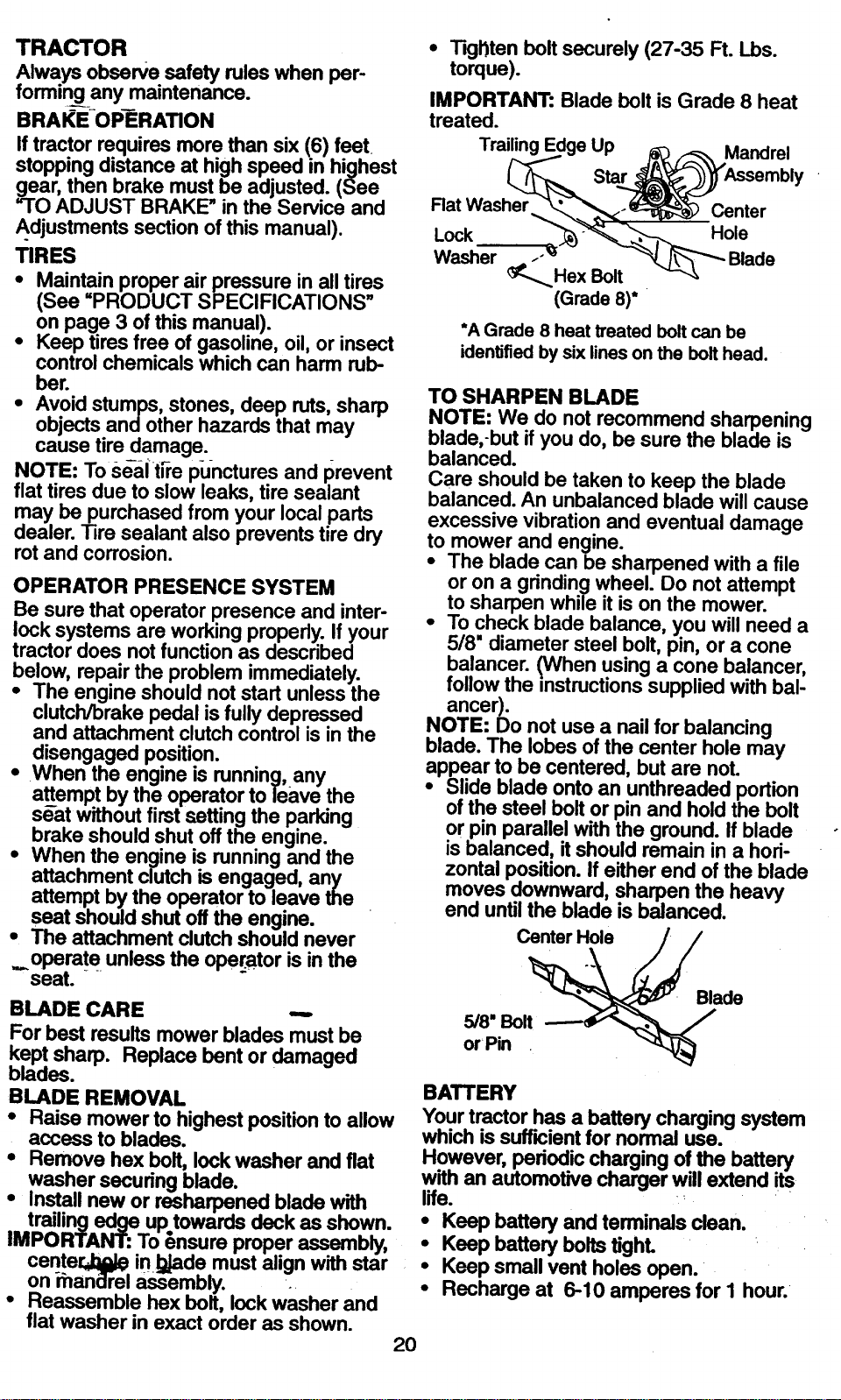
BLADE CARE --,
For best results mower blades must be
kept sharp. Replace bent or damaged
blades.
BLADE REMOVAL
• Raise mower to highest position to allow
access to blades.
• Remove hex bolt, lock washer and fiat
washer securing blade.
• Install new or resharpened blade with
trailing edge up towards deck as shown.
IMPORTANT: To _nsure proper assembly,
cente[J:ljlk_ in !_ade must align with star
on ihanclrel _embly. •
• Reassemble hex bolt, lock washer and
flat washer in exact order as shown.
2O
• Tkji'lten bolt securely (27-35 Ft. Lbs.
torque).
IMPORTANT: Blade bolt is Grade 8 heat
treated.
Trailing Up Mandrel
Star
Rat Washer Center
Lock Hole
Washer .-'_
_...... Hex Bolt
(Grade 8)*
*A Grade 8 heat treated bolt can be
identified by six lines on the bolt head.
TO SHARPEN BLADE
NOTE: We do not recommend sharpening
blade,-but if you do, be sure the blade is
balanced.
Care should be taken to keep the blade
balanced. An unbalanced blade will cause
excessive vibration and eventual damage
to mower and engine.
• The blade can be sharpened with a file
or on a grinding wheel. Do not attempt
to sharpen while it is on the mower.
• To check blade balance, you will need a
5/8" diameter steel bolt, pin, or a cone
balancer. (When using a cone balancer,
follow the instructions supplied with bal-
ancer).
NOTE: Do not use a nail for balancing
blade. The lobes of the center hole may
appear to be centered, but are not.
• Slide blade onto an unthreaded portion
of the steel bolt or pin and hold the bolt
or pin parallel with the ground. If blade
is•balanced, it should remain in a hori-
zontal position. If either end of the blade
moves downward, sharpen the heavy
end until the blade is balanced.
• Baede
5/8 Bolt ----_
orPin
BATTERY
Your tractor has a battery charging system
which is sufficient for normal use.
However, pedodic charging of the battery
with an automotive charger will extend its
life.
• Keep battery and terminals clean.
• Keep battery bolts tighL
• Keep small vent holes open.
• Recharge at 6-10 amperes for I hour.•
IU L/LI-/'_I_I D/'_I I r_..ri!/'_I_IU I r'l'llVlll_t/'_LO
Corrosion a_d dirt on the battery and ter-
minals can cause the battery to "leak"
power.
• Remove-terminal guard.
• Disconnect BLACK battery cable first
then RED battery cable and remove
battery from tractor.
• Rinse the battery with plain water and
dry.
-• Clean terminals and battery cable ends
with wire brush until bright.
• Coat terminals with grease or petroleum
jelly.
• Reinstall battery (See =REPLACING
BATTERY" in the SERVICE AND
ADJUSTMENTS section of this manu-
ai).
V-BELTS
Check V-belts for deterioration and wear
after 100-hours of operation and replace if
necessary. The belts are not adjustable.
Replace belts if they begin to slip from
wear.
TRANSAXLE COOLING
The transmission fan and cooling fins
should be kept clean to assure proper
cooling.
Do not attempt to clean fan or transmis-
sion while engine is running or while the
transmission is hot. ."
• Inspect cooling fan to be sure fan
blades are intact and clean.
• Inspect cooling fins for dirt, grass clip-
pings and other materials. To prevent
damage to seals, do not use com-
-pressed air or high pressure sprayer to
clean cooling fi6s.
TRANSAXLE PUMP FLUID
The transaxle was sealed at the factory
and fluid maintenance is not required for
the life of the transaxle. Should the
transaxle ever leak or require servicing,
,contactyour nearest authorized service
center.
ENGINE
LUBRICATION
Only use high quality detergent oil rated
with API service classification SF, SG, or
SH. Select the oil's SAE viscosity grade
according to your expected operating tem-
perature.
21
_.,||a,ge ,_e u. alter every ou ,ours or
operation or at least once a year ifthe
tractor is not used for 50 hours in one
year.
Check the crankcase oil level before start-
ing the engine and after each eight (8)
hours of operation. Tighten oil fill cap/dip-
stick securely each time you check the oil
level.
TO CHANGE ENGINE OIL
Determine temperature range expected
before oil change. All oil must meet API
service classification SF, SG, or SH.
• Be sure tractor is on level surface.
• Oil will drain more freely when warm.
• Catch oil in a suitable container.
• Remove oil fill cap/dipstick. Be careful
not to allow dirt to enter the engine
when changing oil.
• Remove drain plug.
• After oil has drained completely, replace
oil drain plug and tighten securely.
• Refill engine with oil through oil fill dip-
stick tube. Pour slowly. Do not overfill.
For approximate capacity see =PROD-
UCT SPECIFICATIONS" on page 5 of
this manual.
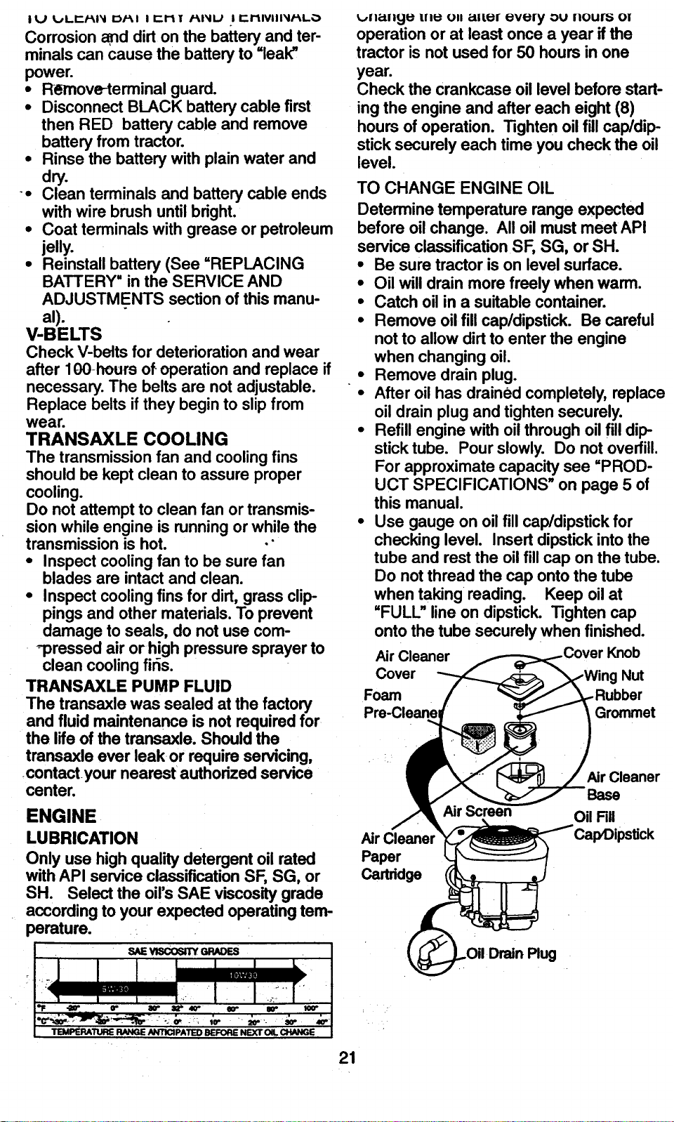
• Use gauge on oil fill cap/dipstick for
checking level. Insert dipstick into the
tube and rest the oil fill cap on the tube.
Do not thread the cap onto the tube
when taking reading. Keep oil at
"FULL" line on dipstick. Tighten cap
onto the tube securely when finished.
Air Cleaner Knob
Cover Nut
Foam ber
Pre-Cleanel Grommet
.&,Jr
Paper
Carlddge
Air Cleaner
Base
Oil nil
CLEAN AIR SCREEN
Air screen must be kept free of dirt and
chaff to prevent engine damage from over-
heatij__g. Clean with a wire brush or com-
pressed air to remove dirt and stubbom
dried gum fibers.
CLEAN AIR INTAKE/COOUNG AREAS
To insure proper cooling, make sure the
grass screen, cooling fins, and other
extemal surfaces of the engine are kept
clean at all times.
Every 100 hours of operation (more often
under extremely dusty,dirtyconditions),
remove the blower housingand other
coolingshrouds. Clean the coolingfins
and extemal surfacesas necessary.Make
sure the coolingshroudsare reinstalled.
NOTE: Operating the engine with a
blocked grass screen, dirty or plugged
cooling fins, and/or cooling shrouds re-
moved will_ause ehgine damage-due to
overheating.
AIR FILTER
Your engine will not run propedy using a
dirty air filter. Clean the foam pre-cleaner
after every 25 hours of operation or every
season. Service paper cartridge every
100 hours of operation or every season,
whichever occurs first.
Service air cleaner more often under dusty
conditions.
• Remove knob and cover.
• Remove wing nut and air cleaner from
base.
TO-SERVICE PRE-CLEANER
• Slide foam pre-creaner offcartridge.
• Wash itin liquiddetergent and water.
• Squeeze it dry ina clean cloth. Allowit
to dry.
• Saturate it in engine oil. Wrap it in
clean, absorbent clothand squeeze to
remove excess oil. ....
TO SERVICE CARTRIDGE
• Replace a dirty, bent, or da_'_ged car-
tddge.
•NOTE: Do not wash the paper cartridge
or use pressurized air, as this will damage
the cartridge.
• Reinstall the pre-cleaner (cleaned and
oiled) over the paper cartridge.
• Reassemble air cleaner, wing nut, cover
and tighten knob securely.
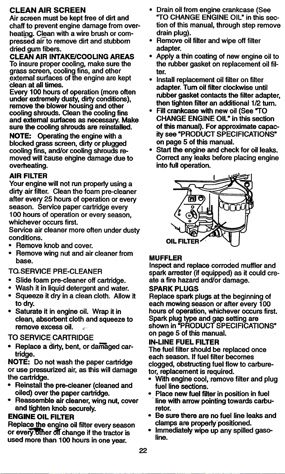
ENGINE OIL FILTER
Replace the enaine oil filter every season
or eve_:--_er _'change if the tractor is
used more than 100 hours in one year.
22
• Drain oil from engine crankcase (See
-TO CHANGE ENGINE OIL" in this sec-
tion of this manual, through step remove
drain plug).
• Remove oil filter and wipe off filter
adapter.
• Apply a thin coating of new engine oil to
the rubber gasket on replacement oil fil-
ter.
• Install replacement oil filter on filter
adapter. Tum oil filter clockwise until
rubber gasket contacts the filter adapter,
then tighten filter an additional 1/2 tum.
• Fill crankcase with new oil (See "TO
CHANGE ENGINE OIL" in this section
of this manual). For approximate capac-
ity see =PRODUCT SPECIFICATIONS"
on page 5 of this manual.
• Start the engine and check for oil leaks.
Correct any leaks before placing engine
into full operation.
OIL
MUFFLER
Inspect and replace corroded muffler and
spark arrester (if equipped) as it could cre-
ate a fire hazard and/or damage.
SPARK PLUGS
Replace spark plugs at the beginning of
each mowing season or after every 100
hours of operation, whichever occurs first.
Spark plug type and gap setting are
shown in =PRODUCT SPECIFICATIONS"
on page 5 of this manual.
IN-LINE FUEL FILTER
The fuel filter should be replaced once
each season. If fuel filter becomes
clogged, obstructing fuel flow to carbure-
tor, replacement is required.
• With engine cool, remove filter and plug
fuel line sections.
• Place new fuel filter in position in fuel
line with arrow pointing towards carbu-
retor.
• Be sure there are no fuel line leaks and
clamps are properlypositioned.
• Immediately wipe up any spilled gaso-
line.
CLEANING
• Clean engine, battery, seat, finish, etc.
of all foreign matter.
• Keep finished surfaces and wheels free
of all gasoline, oil, etc.
• Protect painted surfaces with automo-
tive type wax.
We do not recommend using a garden
hose to clean your tractor unless the elec-
trical system, muffler, air filter and carbure-
tor are covered to keep water out. Water
in engine can result in a shortened engine
life.
,_CAUTION: Before performing any service or adjustments:
• Depress clutch/brake pedal fully and set parking brake.
• Place motion control lever in neutral (N) position.
• Place attachment clutch in =DISENGAGED" position.
• Turn ignition key "OFF" and remove key.
• Make sure-the-blades and all moving parts have completely stopped.
• Disconnect spark plug wire from spark plug and place wire where it cannot come
in contact with plug.
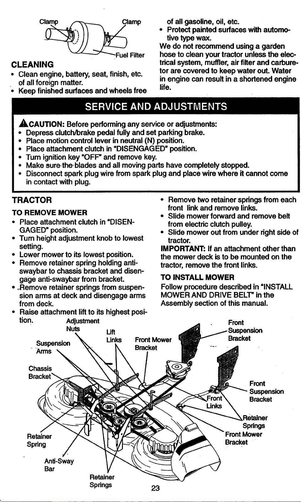
TRACTOR
TO REMOVE MOWER
• Place attachment clutch in =DISEN-
GAGED" position. •
• Turn height adjustment knob to lowest
setting.
• Lower mower to its lowest position.
• Remove retainer spring holding anti-
swaybar to chassis bracket and disen-
gage anti-swaybar from bracket.
• -Remove retainer springs from suspen-
sion arms at deck and disengage arms
from deck.
• Raise attachment lift to its highest posi-
tion. Adjustment
Nuts Uft
Suspension Unks FrontMower
Arms Bracket
• Remove two retainer springs from each
front link and remove links.
• Slide mower forward and remove belt
from electric clutch pulley.
Slide mower out from under right side of
tractor.
IMPORTANT: If an attachment other than
the mower deck is to be mounted on the
tractor, remove the front links.
TO INSTALL MOWER
Follow procedure described in =INSTALL
MOWER AND DRIVE BELT" in the
Assembly section of this manual.
Front
Bracket
Chassis
Bracket_
Front
Suspension
Bracket
Retainer
Spring
/
Anti-Sway
Bar
Retainer
Springs
23
Retainer
Spdngs
Front Mower
Bracket
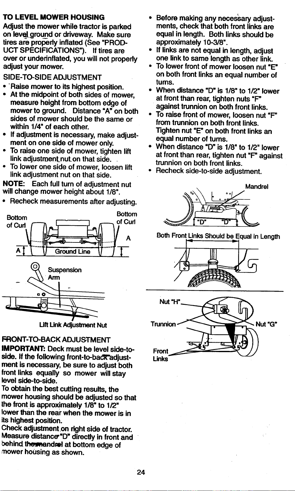
TO LEVEL MOWER HOUSING
Adjust the mower while tractor is parked
on leveLgrou_nd or driveway. Make sure
tires are properly inflated (See "PROD-
UCT SPECIFICATIONS"). If tires are
over or underinflated, you will not propedy
adjust your mower.
SIDE-TO-SIDE ADJUSTMENT
• Raise mower to its highest position.
• At the midpoint of both sides of mower,
measure height from bottom edge of
mower to ground. Distance =A"on both
sides of mower should be the same or
within 1/4" of each other.
• If adjustment is necessary, make adjust-
ment on one side of mower only.
• To raise one side of mower, tighten lift
link adjustment_nuLon that side.
• To lower one side of mower, loosen lift
link adjustment nut on that side.
NOTE: Each full turn of adjustment nut
will change mower height about 1/8".
• Recheck measurements after adjusting.
Bottom Bottom
of Curl _ I I _ of Curl
Suspension
Arm
• Before making any necessary adjust-
ments, check that both front links are
equal in length. Both links should be
approximately 10-3/8".
• If links are not equal in length, adjust
one link to same length as other link.
• To lower front of mower loosen nut "E"
on both front links an equal number of
tums.
• When distance "D" is 1/8" to 1/2" lower
at front than rear, tighten nuts =F"
against trunnion on both front links.
• To raise front of mower, loosen nut =_
from trunnion on both front links.
Tighten nut "_ on both front links an
equal number of tums.
• When distance =D" is 1/8" to 1/2" lower
at front than rear, tighten hut =F" against
trunnion on both front links.
• Recheck side-to-side adjustment.
Mandrel
Both FrontUnks Shouldbe Equalin Length
Nut "H"
Uft Link Adjustment Nut
FRONT-TO-BACK ADJUSTMENT
IMPORTANT: Deck must be level side-to-
side. ff the following front-to-badl_"adjust-
ment is necessary, be sure to adjust both
front links equally so mower will stay
level side-to-side.
To obtain the best cutting results, the
mower housing should be adjusted so that
the front is appro_mately 1/8" to 1/2"
lower than the rear when the mower is in
its highest position.
Check adjustment on right side of tractor.
Measure distance"D" directly in front and
behind _ndml at bottom edge of
mower housing as shown.
Trunnion Nut "(3"
Front
Links
24
TO REPLACE MOWER DRIVE BELT
MOWER DRIVE BELT REMOVAL
• Park tractor on a level surface. Engage
pa_'-r_g bTake.
• Remove screws from left hand mandrel
cover and remove cover.
• Roll belt over the top of left hand man-
drel pulley.
Removebelt from electric clutch pulley.
Remove belt from idler pulleys.
Remove any dirt or grass clippings
which may have accumulated around
mandrels and entire upper deck sur-
face.
• Check primary idler arm and two idlers
to see that they rotate freely.
• Be sure spdng is securely hooked to pri-
mary idler arm and belt in mower hous-
ing.
MOWER DRIVE BELT INSTALLATION
• Install belt in both idlers. Make sure belt
is in both belt keepers at the idlers as
shown.
• Install new belt onto electric clutch pul-
ley.
• Roll belt into upper groove of left hand
mandrel pulley.
• Carefully check belt routing making sure
belt is in the grooves correctly and
inside belt keepers.
• Reassemble left hand mandrel cover.
i-eft I:tand
Mandrel
Cover
Screws
Idler
Pulleys
Electric
Clutch
Mower
Drive Belt
Left
Mandrel
Pdmary
Idler Arm
Belt
Keepers
25

TO REPLACE MOWER BLADE DRIVE
BELT
Parkthe tractoron levelsurface. Engage
parkiagbrake.
• Remove mower drive belt (See "TO
REPLACE MOWER DRIVE BELT" in
this section of this manual).
• Remove mower (See "TO REMOVE
MOWER" in this section of this manual).
•- Remove four screws from right hand
mandrel cover and remove cover.
Unhook spring from bolt on mower
housing.
• Carefully roll belt off right hand mandrel
pulley.
• Remove belt from center mandrel pul-
ley, idler pulley, and left hand mandrel
pulley.
• Remove any dirt or grass which may
have accumulated around mandrels ano
entire upper deck surface.
Left Hand Mower Blade
Mandrel Ddve Belt
• Check secondary idler arm and idler to
see that they rotate freely.
• Be sure spring is hooked in secondary
idler arm and sway-bar bracket.
• Install new belt in lower groove of left
hand mandrel pulley, idler pulley, and
center mandrel pulley as shown.
• Roll belt over right hand mandrel pulley.
Make sure belt is in all grooves properly.
• Reconnect spring to belt in mower
housing and reinstall right hand mandrel
cover.
° Reinstall mower to tractor (See
"INSTALL MOWER AND DRIVE BELT"
in the Assembly section of this manual).
• Reassemble mower drive belt (See "TO
REPLACE MOWER DRIVE BELT" in
this section of this manual).
Center
Mandrel Idler
Pulley
Secondary
Idler Arm
Spring,
Bracket Screw
Right Hand
Mandrel
Cover
TO ADJUST BRAKE
Your tractor is equipped with an adjustable
brake system which is mounted on the
side of the transaxle.
If tractor requires more than six (6) feet
stopping distance at high .speed..in.hi_]h-
estgeaf, then brake mustbe aojustea.
• Depress clutch/brake pedal and engage
parking brake. --,
• Measure distance between brake oper-
ating arm and nut "A" on brake rod.
If distance is other than 1-9/16", loosen
jam nut and tum nut "A" until distance
becomes 1-9/16". Retighten jam nut
against nut "A'.
° Road test tractor for proper stopping
distance as stated above.. Readjust
necessary. If stopping aistance kssti,
greater than six (6) feet in highest gear,
further maintenance is necessary.
ContOur. rjg..arest authorized ser-
vice ce_'i_r/de]_artment.
With ParkingBrake "Engaged"
I"A"
Jam Nut
Am1
Do Not touch this nut. If further brake adjust-
ment is necessary contact your nearest autho-
dzed service center/department
26
TO REPLACE MOTIONDRIVEBELT
Parkthe tractor on levelsurface. Engage
parkingbrake. For assistance,there isa
belt_stallation guide decal on bottom
side of left footrest.
• Remove mower (See rl'O REMOVE
MOWER" in this section of this manual.)
• Disconnect clutch wire harness.
• Remove clutch Iocator.
• Remove belt from stationary idler and
clutching idler.
• Pull belt slack toward rear of tractor.
Carefully remove belt upwards from
transmission input pulley and over cool-
ing fan blades.
• Pull belt toward front of tractor and
remove downwards from around electric
clutch.
• Install newbelt by reversing above pro-
cedure.
Clutch Locator
Clutching
Idler
Idler Clutch
Wire Harness
Transmission
Input Pulley"
TO ADJUST MOTION CONTROL LEVER
The motion control lever has been preset
at the factory and adjustment should not
_. be necessary. _
If for any reason the motion control lever
will not hold its position while, at a selected
speed, it may be adjusted at the friction
pack located on the right side of transmis-
sion.
• Park tractor on level surface. Stop trac-
tor by tuming ignition key to "OFF" posi-
tion, and engage parking brake.
• Adjust motion control lever by tightening
adjustment Iocknut one half (1/2) tum.
NOTE: If for any reason the effort to
move the motion control lever becomes
too _siv_=a'everse the above adjust-
m_nt proceciure by loosening Iocknut 114
to 112turn.
Road test tractor after adjustment and
repeat procedure if necessary.
TRANSMISSION REMOVAl/REPLACE-
MENT
Should your transmissionrequire removal
for service or replacement, it shouldbe
purged after reinstallationand before
operating the tractor. See _'PURGE
TRANSMISSION" inthe Operation section
of this manual.
Adjustment
Locknut
TO ADJUST STEERING WHEEL ALIGN-
MENT
If steering wheel crossbars are not hori-
zontal (left to right) when wheels are posi-
tioned straight forward, remove steering
wheel and reassemble per instructions in
the Assembly section of this manual.
FRONT WHEEL TOE-IN/CAMBER
The front wheel toe-in and camber are not
adjustable on your tractor. If damage has
occurred to affect the front wheel toe-in or
camber, contact your nearest authorized
service center.
TO REMOVE WHEEL FOR REPAIRS
• Block up axle securely.
• Remove axle cover, retaining ring and
washers to allow wheel removal (rear
wheel contair_s a square key - Do not
lose):
• Repair tire and reassemble.
• On rear whei_ls only: align grooves in
rear wheel hub and axle. Insert square
key.
• Replace washers and snap retaining
ring securely in axle groove.
• Replace axle cover.
NOTE: To seal tire punctures and prevent
flat tires due to slow leaks, tire sealant
may be purchased from your local parts
dealer. Tire sealant also prevents tire dry
rot and corrosion.
27

Washers A
Retaining '_ ff__lJ
R'ng-_-_'____] I
AxleCover "_Square ey
(Rear Wheel Only)
TO START ENGINE THAT HAS A WEAK
BATTERY
ACAUTION: Lead-acid batteries gener-
ate explosive gases. Keep sparks, flame
and smoking materials away from batter-
ies. Always wear eye protection when
around batteries.
If your battery is too weak to start the
engine, it should be recharged. (See
"BATTERY" in the MAINTENANCE sec-
tion of this manual). _
If "jumper cables" are used for emergency
starting, follow this procedure:
IMPORTANT: Your tractor Is equiped with
a 12 volt negative grounded system. The
other vehical must also be a 12 volt nega-
tive grounded system. Do not use your
tractor battery to start other vehicals.
TO ATTACH JUMPER CABLES -
• Connect each end of the RED cable to
the POSITIVE (+) terminal of each bat-
tery, taking care not to short against
chassis.
• Connect one end of the BLACK cable to
the NEGATIVE (-) terminal of fully
charged battery.
, Connect the other end of the BLACK
cable to good CHASSIS GROUND,
away from fuel tank and battery.
I'O REMOVE CABLES, REVERSE
_)RDER -
• BLACK cable first from chassis and
then from the fully charged battery.
0 RED cable last from both batteries.
- ._ -. - .:=.
..H._lt_Panel
IEPLACING BATTERY
LCAUTION: Do not short battery termi-
als by allowing a wrench or any other
bject to contact beth terminals at the
ame time. Before connecting battery,
•_move-mlJlEfl:)rac_lbts, wristwatch
ands,rings,etc.
Positive terminal must be connected first
to prevent sparking from accidental
grounding.
• Lift hood to raised position.
• Remove terminal guard.
• Disconnect BLACK battery cable then
RED battery cable and carefully remove
battery from tractor.
• Install new battery with terminals in
same position as old battery.
• Reinstall terminal guard.
• First connect RED battery cable to posi-
tive (+) battery terminal with hex bolt
and keps nut as shown. Tighten secure-
l.ly
• (_onnectBLACK groundingcableto
negative(-)batteryterminalwith
remaininghex boltand keps nut.
Tightensecurely
• Close terminal access doors.
• Close hood.
Terminal keps Nut
Access
Door
: Hex Bolt
•,- Positive
• Cable
Terminal
Guard
(Black) Cable
TO REP!.ACE HEADLIGHT BULB
• Raise hood.
• Pull bulb holder out of the hole in the
backside of the grill.
• Replace bulb in holder and push bulb
holder securely back into the hole in the
backside of the grill.
• Close hood.
INTERLOCKS AND RELAYS
Loose or damaged wiring may. cause your
tractorto run poorly, stop running, or pre-
vent it from starting.- "
• Check widng. See electrical widng dia-
gram in the Repair Parts section of this
manual.
TO REPLACE FUSE
Replace with 30 amp automotive-type
plug-in fuse. The fuse holder is located
behind the dash.
TO REMOVE HOOD AND GRILL
ASSEMBLY
• Raise hood.
• Unsnap headlight wire connector.
• Stand Jnfront of tractor. Grasp hood at
sides, tilttoward engine and lift off of
tractor.
• To replace, reverse above procedure.
28
Hood
Headlight
Wire
Connector
ENGINE
Maintenance, repair, or replacement of the
emission control devices and systems,
which are being done at the customers
expense, may be performed by any non-
road engine repair establishment or indi-
vidual. Warranty repairs must be per-
formed by an authorized engine manufac-
turer's service outlet.
TO ADJUST "rHR_OTTLE CONTROL
CABLE
The throttle control has been preset at the
factory and adjustment should not be nec-
essary. Check adjustment as described
below before loosening cable. If adjust-
ment is necessary, proceed as follows:
• With engine not running, move throttle
control lever from slow to choke posi-
tion. Slowly move lever from choke to
fast position.
• Check to see if hole in throttle lever and
hole in speed control bracket are
aligned.
• If holes are not aligned, loosen cable
clamp screw and align the holes by
inserting a pencil or a 1/4" drill bit
-.- through bothholes.
Cable Clamp
Screw
Speed Control
Bracket
Lever
TO ADJUST CARBURETO'_
The carburetor has been preset at the fac-
tory and adjustment should not be neces-
sary. However, minor adjustment may be
required to compensate for differences in
fuel, temperature, altitude or load. Ifthe
carburetor does need adjustment, proceed
as follows:
In general, tuming the adjusting needles
In (clockwise) decreases the supply of fuel
to the engine giving a leaner fuel/air mix-
ture,Tuming the adjusting _needles out
(co_loekwise) increases the supply of
fuel t_>the engine giving a richer fuel/air
mixture.
3(5
29
IMPORTANT: Damage to the needles and
the seats in carburetormay result if nee-
dle is turned in too tight.
NOTE: The carburetor on this engine is
low emission. It is equipped with an idle
fuel adjusting needle with a limiter cap,
which allows some adjustment within the
limits allowed by the cap. Do not attempt
to remove the limiter cap. The limiter cap
cannot be removed without breaking the
adjusting needle.
• Be sure you have a clean air filter and
the throttle control cable is adjusted
properly (see above).
• Start engine and allow to warm for five
minutes. Make adjustments with engine
running and shift/motion control leverin
neutral (N) position.
• Idle soeed setting - With throttle control
lever in slow position, engine should
idle at 1750 RPM. If engine idles too
slow or fast, turn idle speed adjusting
screw in or out until correct idle is at-
tained.
• Idle fuel needle Setting - With throttle
control lever in slow position, turn idle
fuel adjustment needle in (clockwise)
until engine begins to die and then tum
out (counterclockwise) until engine runs
rough. Tum needle to a point midway
between those two positions.
• Recheck idle speed. Readjust if neces-
sary.
ACCELERATION TEST
• Move throttle control lever from slow to
fast position. If engine hesitates or dies,
tum idle fuel adjusting needle out (coun-
terclockwise) 118 tum. Repeat test and
continue to adjust, if necessary, until
• engine •accelerates smoothly.
High speed stop is factory adjusted. Do
not adjust - damage may result.
IMPORTANT: Never tamper with the
engine governor, which is factory set for
proper engine speed. Overspeeding the
engine above the factory high speed •set-
ting can be dangerous. If you think the
engine-govemed high speed needs
adjusting, contact your nearest AUTHO-
RIZED service center, which has proper
equipment and experience to make any
necessary adjustments.
IdleSpeed
Adjusting
Screw
Idle Fuel
Needle,
Immediately prepare yourtractorfor stor-
ageatthe-end of the season or if the trac-
tor will notbe used for 30 days or more.
ACAUTION: Never storethe tractorwith
gasoline in the tank insidea building
where fumes may reach an openflame or
spark. Allowthe engine to coolbefore stor-
ing inany enclosure.
TRACTOR
Remove mower from tractor for winter
storage. This willallow you to clean itthor-
oughly. Remove all dirt, grease, leaves,
etc. Store in a clean, dry area.
• Clean entire tractor (See =CLEANING"
in the Maintenance section of this man-
uali. ........
• Inspect and replace belts, if necessary
(See belt replacement instructions in the
Service and Adjustments section of this
manual).
• Lubricate as shown in the Maintenance
section of this manual.
• Be sure that all nuts, bolts and screws
are securely fastened. Inspect moving
parts for damage, breakage and wear.
Replace if necessary.
• Touch up all rusted or chipped paint sur-
faces; sand lightly before painting.
BATTERY
• Fully charge the battery for storage.
• After a period of time in storage, battery
nay require recharging.
• To help prevent corrosion and power
leakage during long periods of storage,
battery cables should be disconnected
and battery cleaned thoroughly (see
"TO CLEAN BATTERY AND TERMI-
NALS" in the Maintenance section of
this tnanual).
• After cleaning, leave cables disconnect-
ed and place cables where t'_'ey cannot
come in contact with battery terminals.
• If battery is removed from tractor for
storage, do not store battery directly on
concrete or damp surfaces.
ENGINE
FUEL SYSTEM
IMPORTANT: It is important to prevent
gum deposits from forming in essential
fuel system parts such as carburetor, fuel
filter,.f_e,_rtank during storage.
Also, experience indicates that alcohol
blended fuels (called gasohol or using
ethanol or methanol) can attract moisture
which leads to separation and formation of
acids during storage. Acidic gas can dam-
age the fuel system of an engine while in
storage.
• Drain the fuel tank.
• Start the engine and let it run until the
fuel lines and carburetor are empty.
• Never use engine or carburetor cleaner
products in the fuel tank or permanent
damage may occur.
• Use fresh fuel next season.
NOTE: Fuel stabilizer is an acceptable
altemative in minimizing the formation of
fuel gum deposits during storage. Add sta-
bilizer to gasoline in fuel tank or storage
container. Always follow the mix ratio
found on stabilizer container. Run engine
at least 10 minutes after adding stabilizer
to allow the stabilizer to reach the carbure-
tor. Do not drain the gas tank and carbure-
tor if using fuel stabilizer.
ENGINE OIL
Drain oil (with engine warm) and replace
with clean engine oil. (See "ENGINE" in
the Maintenance section of this manual).
CYUNDER(S)
• Remove spark plug(s).
• Pour one ounce of oil through spark plug
hole(s) into cylinder(s).
• Tum ignition key to "START" position for
a few seconds to distribute oil.
• Replace with new spark plug(s).
OTHER
• Do not store gasoline from one season
to another.
• Replace your gasoline can if it starts to
rust. Rust and/or dirt in your gasoline will
cause problems.
• If possible, store your tractor indoors
and cover it to give protection from dust
and dirt.
• Cover your tractor with a suitable protec-
•tive cover that does not retain moisture.
Do not use plastic. Plastic cannot
breathe, which allows condensation to
form and cause your tractor to rust.
IMPORTANT: Never cover tractor while
engine and exhaust areas are still warm.
3O
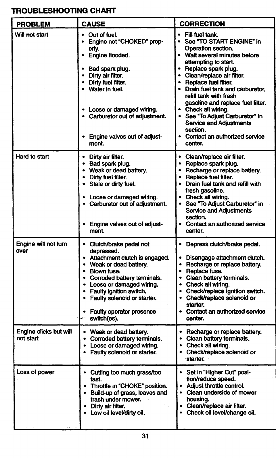
TROUBLESHOOTING CHART
PROBLEM
Will-not sta_
Hard to start
Engine will not turn
over
Engine clicks but will
not start
Loss of power
CAUSE
• Out of fuel.
• Engine not"CHOKED" prop-
• Engine flooded.
• Bad spark plug.
• Dirty air filter.
• Dirty fuel filter.
• Water in fuel.
• Loose or damaged wiring.
• Carburetor out of adjustment.
• Engine valves out of adjust-
ment.
• Dirty air filter.
• Bad spark plug.
• Weak or dead battery.
• Dirty fuel filter.
• Stale or dirty fuel.
• Loose or damaged wiring.
• Carburetor out of adjustment.
• Engine valves out of adjust-
ment.
• Clutch/brake pedal not
depressed.
• Attachment dutch is engaged.
• Weak or dead battery.
• Blown fuse.
• Corroded battery terminals.
• Loose or damaged wiring.
• Faulty ignition switch.
• Faulty solenoid or starter.
• Faulty operator presence
_ switch(es).
• Weak or dead battery.
• Corroded battery terminals.
• Loose or damaged wiring.
• Faulty solenoid or starter.
• Cuffing too much grass/too
fast.
* Throttle in "CHOKE" position.
• Build-up of grass, leaves and
trash under mower.
• Dirty air filter.
• Low oil level/dirty oil.
CORRECTION
• Fill fuel tank.
• See "TO START ENGINE" in
Operation section.
• Wait several minutes bafom
attempting to start.
• Replace spark plug.
• Clean/replace air filter.
• Replace fuel filter.
• " Drain fuel tank and carburetor,
refill tank with fresh
gasoline and replace fuel filter.
• Check all widng.
• See "To Adjust Carburetor" in
Service and Adjustments
section.
• Contact an authorized service
center.
• Clean/replace air filter.
• Replace spark plug.
• Recharge or replace battery.
• Replace fuel filter.
• Drain fuel tank and refill with
fresh gasoline.
• Check all wiring.
• See "To Adjust Carburetor" in
Service and Adjustments
section.
• Contact an authorized service
center.
• Depress dutch/brake pedal.
• Disengage attachment clutch.
• Recharge or replace battery.
• Replace fuse.
• Clean battery terminals.
• Check all wiring.
• Check/replace ignition switch.
• Check/replacesolenoidor
starter.
• Contact an authorized service
center.
• Recharge or replace battery.
• Clean battery terminals.
• Check all wiring.
• Check/replace solenoid or
starter.
• Set in "Higher Cut" posi-
tiordmduce speed.
• Adjust throttle control.
• Clean underside of mower
housing.
• ClearVreplace air filter.
• Check oil level/change oil.
31
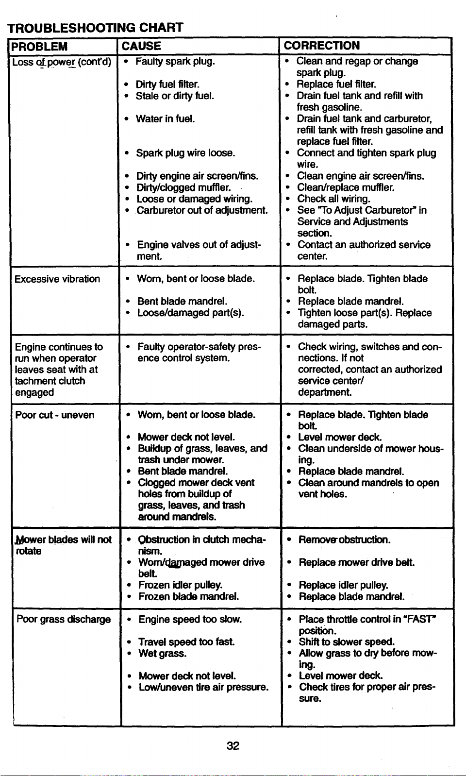
PROBLEM CORRECTION
I
!Loss o[power (cont'd)
TROUBLESHOOTING CHART
CAUSE
• Faulty spark plug.
Excessive vibration
Engine continues to
run when operator
leaves seat with at
tachment clutch
engaged
Poor cut - uneven
JL4ower_ades will not
rotate
Poor grass discharge
• Dirty fuel filter.
• Stale or dirty fuel.
• Water in fuel.
• Spark plug wire loose.
• Dirty engine air screen/fins.
• Dirty/clogged muffler.
• Loose or damaged wiring.
• Carburetor out of adjustment.
• Engine valves out of adjust-
ment
• Wom, bent or loose blade.
• Bent blade mandrel.
• Loose/damaged part(s).
• Faulty operator-safety pres-
ence control system.
•Wom, bent or loose blade.
, Mower deck not level.
• Buildup of grass, leaves, and
trash under mower.
• Bent blade mandrel.
• Clogged mower deck vent
holes from buildup of
grass, leaves, and trash
around mandrels.
• Obstru_on in dutch mecha-
nism.
• Wom/(_naged mower drive
belL
• Frozen idler pulley.
• Frozen blade mandrel.
• Engine speed too slow.
• Travel speed too fast.
• Wet grass.
• Mower deck not level.
• Low/uneven tire air pressure.
• Clean and regap or change
spark plug.
• Replace fuel filter.
• Drain fuel tank and refill with
fresh gasoline.
• Drain fuel tank and carburetor,
refill tank with fresh gasoline and
replace fuel filter.
• Connect and tighten spark plug
wire.
• Clean engine air screen/fins.
• Clean/replace muffler.
• Check all wiring.
• See "To Adjust Carburetor" in
Service and Adjustments
section.
• Contact an authorized service
center.
• Replace blade. Tighten blade
bolt.
• Replace blade mandrel.
• Tighten loose part(s). Replace
damaged parts.
Check wiring, switches and con-
nections. If not
corrected, contact an authorized
service center/
department.
• Replace blade. Tighten blade
bolt.
• Level mower deck.
• Clean underside of mower hous-
ing.
• Replace blade mandrel.
• Clean around mandrels to open
vent holes.
i
• Remover obstruction.
• Replace mower drive belt.
• Replace idler pulley.
• Replace blade mandrel.
• Place throttle control in "FAST"
pos on.
• Shift to slower speed.
• Allow grass to dry before mow-
ing.
• Level mower deck.
• Check tires for proper air pres-
sure.
32

'ROUBLESHOOTING CHART
PROBLEM
'oor grass discharge
:onrd)
4eadlight(s) not work
_g (if so equipped)
_attery will not charge
.oss of drive
!ngine_=backfires"
ihen turning engine
OFF"
CAUSE
• Wom, bentor looseblade.
• Buildup of grass, leaves and
trash under mower.
• Mower drive belt worn.
• Blades improperly installed.
• Improper blades used.
Clogged mower deck vent
holes from buildup of
grass, leaves, and trash
around mandrels.
• Switch is "OFF".
• Bulb(s) bumed out.
• Faulty light switch.
-,_ Loose or damaged wiring.
• Blown fuse.
• Bad battery cell(s).
• Poor cable connections.
• Faulty regulator (if so
equipped).
• Faulty alternator.
• Freewheel control in "disen-
gaged" position.
• Motion drive belt worn, dam-
aged or broken.
• Air trapped in transmission
during shipment
or servicing.
• Engine throttle control not set
at "SLOW" position for 30 sec-
onds before stopping engine.
CORRECTION
• Replace/sharpen blade. Tighten
blade bolt.
• Clean underside of mower
housing.
• Replace mower drive belt.
• Reinstall blades sharp edge
down.
• Replace with blades listed in
this manual.
• Clean around mandrels to open
vent holes.
• Turn switch "ON".
• Replace bulb(s).
• Check/replace light switch.
• Check wiringand connections.
• Replace fuse.
• Replace battery.
• Check/clean all connections.
• Replace regulator.
• Replace altemator.
• Place freewheel control in
"engaged" position.
• Replace motion drive belt.
• Purge transmission.
Move throttle control to "SLOW"
position and allow to idle for 30
seconds before stopping
engine.
33

34
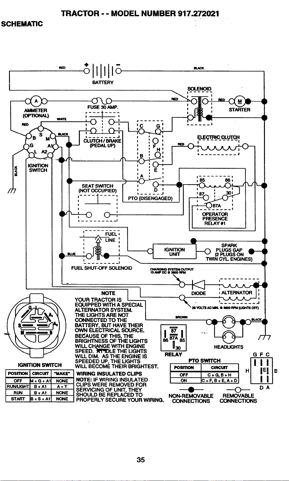
SCHEMATIC
TRACTOR - - MODEL NUMBER 917.272021
I
I
FUEL SHUT-OFF SOLENOID
NOTE [
YOUR TRACTOR IS
EQUIPPED WiTH A SPECIAL
ALTERNATOR SYSTEM.
IGNmON SWITCH
THE LIGHTS ARE NOT
CONNECTED TO THE
BATTERY, BUT HAVE THEIR
OWN ELECTRICAL SOURCE.
BE_:AUSE OF THIS, THE
BRIGHTNESS OF THE LIGHTS
WILL CI'I_NGE WITH ENGINE
SPEED. RRRDLE THE UGHTS
WILL DIM. AS THE ENGINE IS
SPEEDED UP, THE LIGHTS
BROWN
"":1
RELAY
HEADLIGHTS
WILL BECOME THEIR BRIGHTEST.
WIRING INSULATED CUPS
NOTE: IF WIRING INSULATED
i CLIPS WERE REMOVED FOR
SERVICING OF UNIT, THEY
SHOULD BE REPLACED TO
PROPERLY SECURE YOUR WIRING.
GFC
Fro SWITCH
i--I
OFF 'C+G,B+H I
ON C+F,B+E,A+D I
.9) (_ DA
NON-REMOVABLE REMOVABLE
CONNECTIONS CONNECTIONS
35
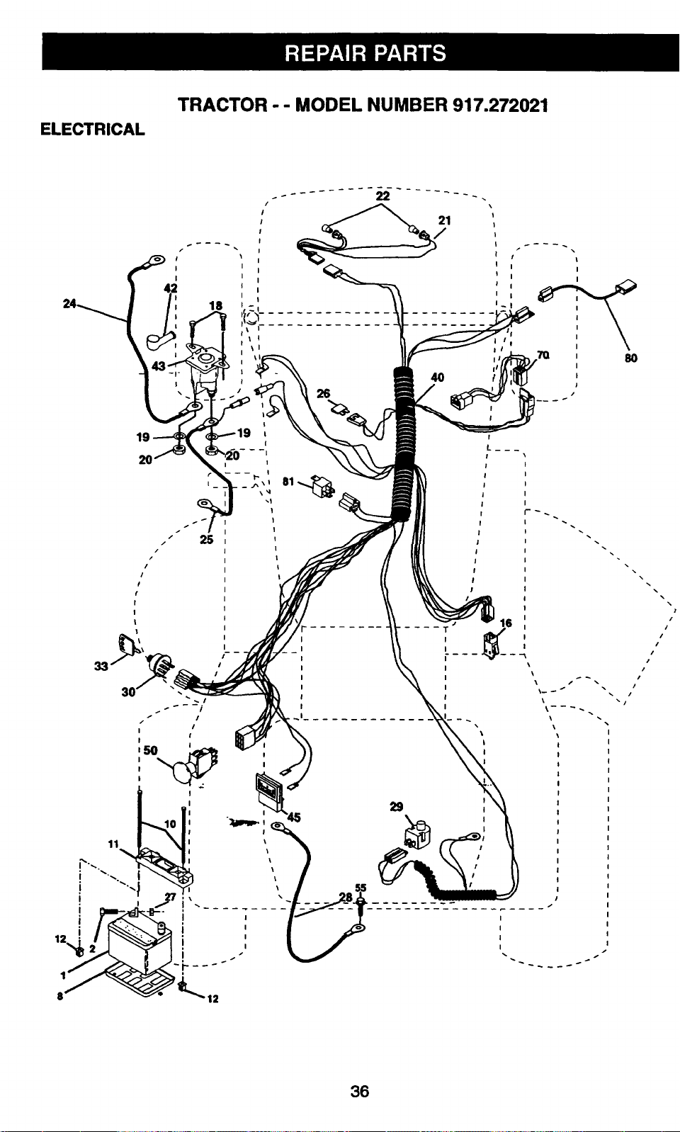
ELECTRICAL
TRACTOR - - MODEL NUMBER 917.272021
19
3O
!
I
16
\
\
t
I
\
\
I
I
i I
I
ii
36
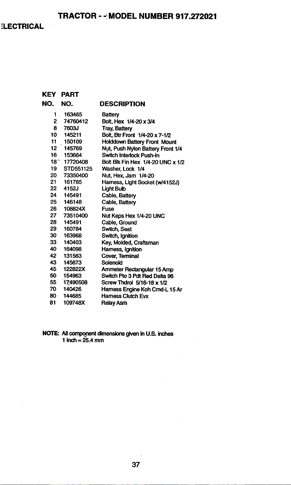
"LECTRICAL
TRACTOR - -_MODEL NUMBER 917.272021
KEY
NO.
PART
NO. DESCRIPTION
1 163465 Battery
2 74760412 Bolt, Hex 1/4-20x3/4
8 7603J Tray, Battery
10 145211 Bolt, Btr Front 114-20 x 7-1/2
11 150109 Holddown Battery Front Mount
12 145769 N.ut,Push Nylon Battery Front 1/4
16 153664 Switch Interlock Push-in
i8- 17720408 Bolt BIk Fin Hex 1/4-20 UNC x 1/2
19 STD551125 Washer, Lock 1/4
20 73350400 Nut, Hex, Jam 1/4-20
21 161785 Harness, LightSocket (w/4152J)
22 4152J LightBulb
24 145491 Cable, Battery
25 146148 Cable, Battery
26 108824X Fuse
27 73510400 Nut Keps Hex 1/4-20 UNC
28 145491 Cable, Ground
29 160784 Switch, Seat
30 163968 Switch, Ignition
33 140403 Key, Molded, Craftsman
40 164098 Harness, Ignition
42 131563 Cover, Terminal
43 145673 Solenoid
45 1_822X Ammeter Rectangular 15 Amp
50 154963 Switch Pto 3 Pdt Red Delta 96
55 17_490508 Screw Thdrol 5/16-18 x 1/2
70 140426 Hamess Engine Koh Cmd-L 15 Ar
80 144685 Hamess Clutch Evx
81 109748X RelayAsm
NOTE: All_t dimensionsgiveninU.S. inches
1 inch= 25.4 mm
37
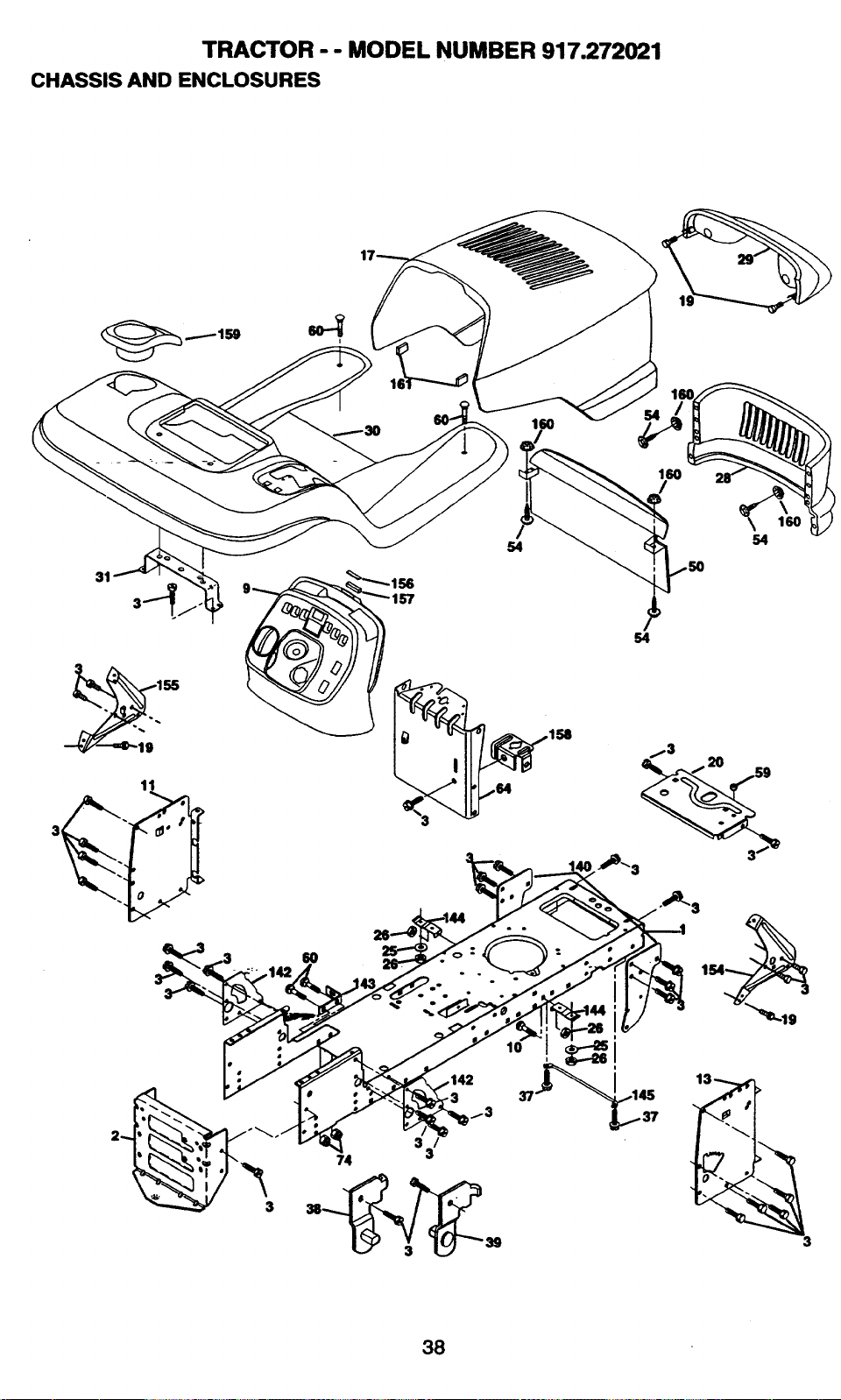
TRACTOR -- MODEL NUMBER 917.272021
CHASSIS AND ENCLOSURES
31
11
5O
<
150
I
180
I /
5O
54
158
_3
._"S 3--
i
3
3 /
74 3
38
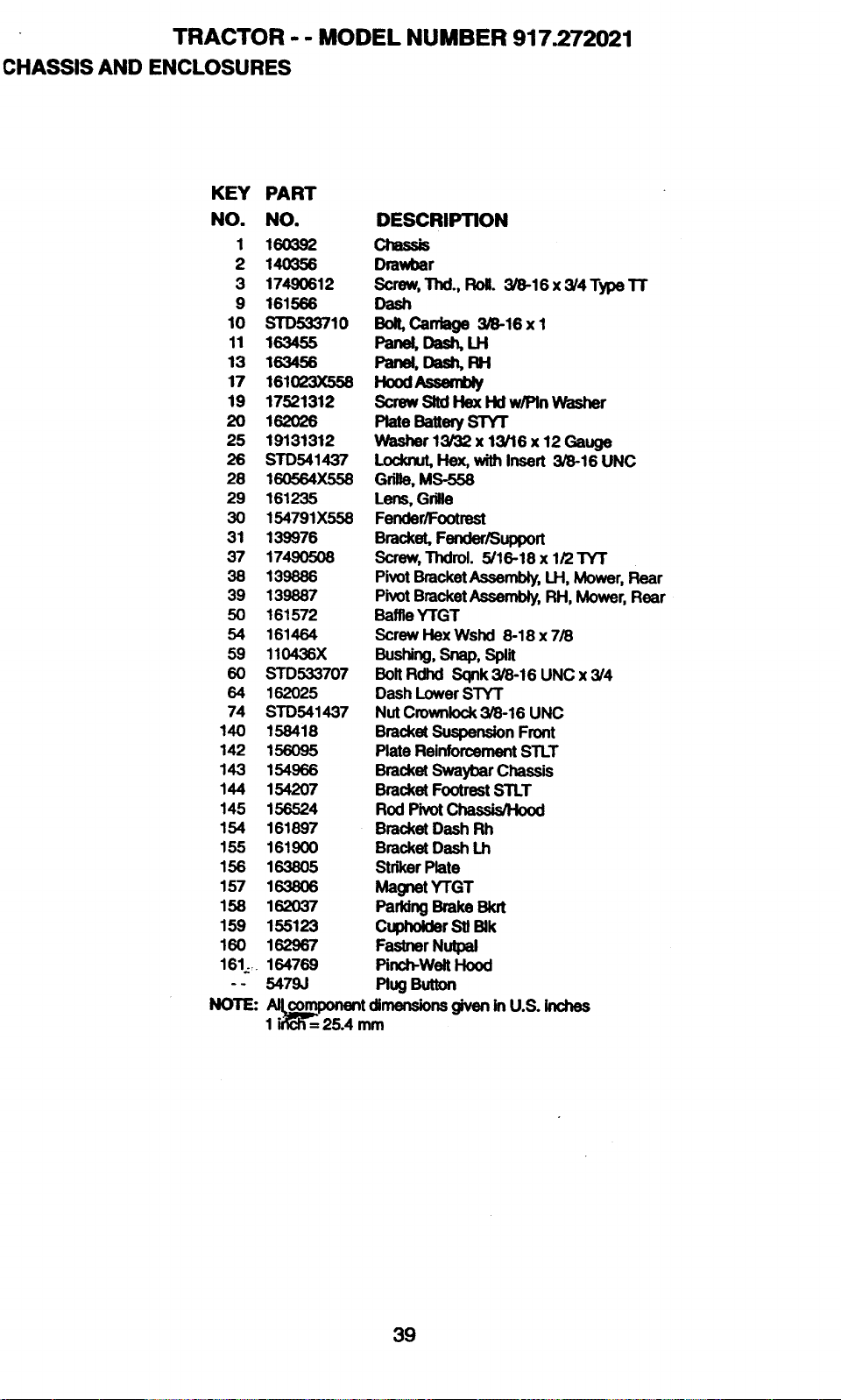
TRACTOR - - MODEL NUMBER 917.272021
CHASSIS AND ENCLOSURES
KEY PART
NO. NO.
1 160392
2 140356
3 17490612
9 161566
10 STD533710
11 163455
13 163456
17 161023X556
19 17521312
20 162026
25 19131312
26 STD541437
28 160564X558
29 161235
30 154791X556
31 139976
37 174905O8
38 139886
39 139887
50 161572
54 161464
59 110436X
60 STD533707
64 162025
74 STD541437
140 158418
142 156095
143 154966
144 154207
145 156524
154 161897
155 161900
156 1638O5
157 163806
156 162037
159 155123
160 162967
161_ 164769
- - 5479J
NOTE:
DESCRIPTION
Chassis
Drawbar
Screw, Thd., Roll. 3/8-16 x 3/4TypeTT
Dash
Bolt, Cardage 3/8-16 x 1
Panel,Dash,Ut
Panel,Das_ RH
HoodAsserr_
Screw Slid Flex I-Id w/Pin Washer
Plate Battery STY1"
Washer 13/32 x 13/16 x 12 Gauge
Locknut, Flex, with Insert 3/8-16 UNC
Grilla, MS-556
Lens, Grille
Fender/Footrest
Bracket, Fender/Support
Screw, Thdrol. 5/18-18 x 1/2 TYT
Pivot Bracket Assembly, LH, Mower, Rear
Pivot Bracket Assembly, RH, Mower, Rear
Baffle YTGT
Screw Hex Wshd 8-18x 7/8
Busing,Snap,Sp_
BoltRdhd Sqnk 3/8-16 UNC x3/4
Dash Lower STYT
Nut Crownlock 3/8-16 UNC
Bracket Suspension Front
Plate Reinforcement STLT
Bracket Swaybar Chassis
Bracket Footrest STLT
Rod Pivot Chassis/Hood
Bracket Dash Rh
Bracket Dash Lh
Striker Plate
Magnet YTGT
Paddng Brake Blot
Cuphok:larSU Bik
Fastner Nutl_
Pinch-Welt Hood
Plug Button
_mponent dimensionsgiveninu.s. k_ches
1 i_:h-= 25.4 mm
39
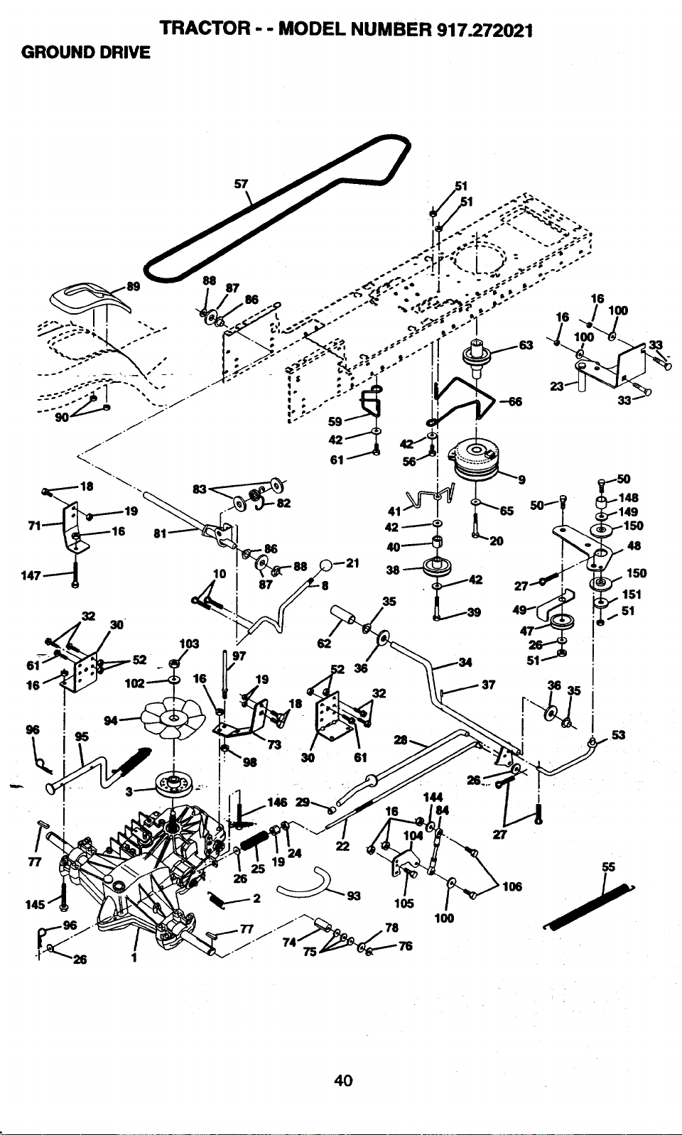
TRACTOR - - MODEL NUMBER 917.272021
GROUND DRIVE
i
77 9 24
22
_._-- 2 93 105
27
I06
55
100
53
48
150
151
51
40
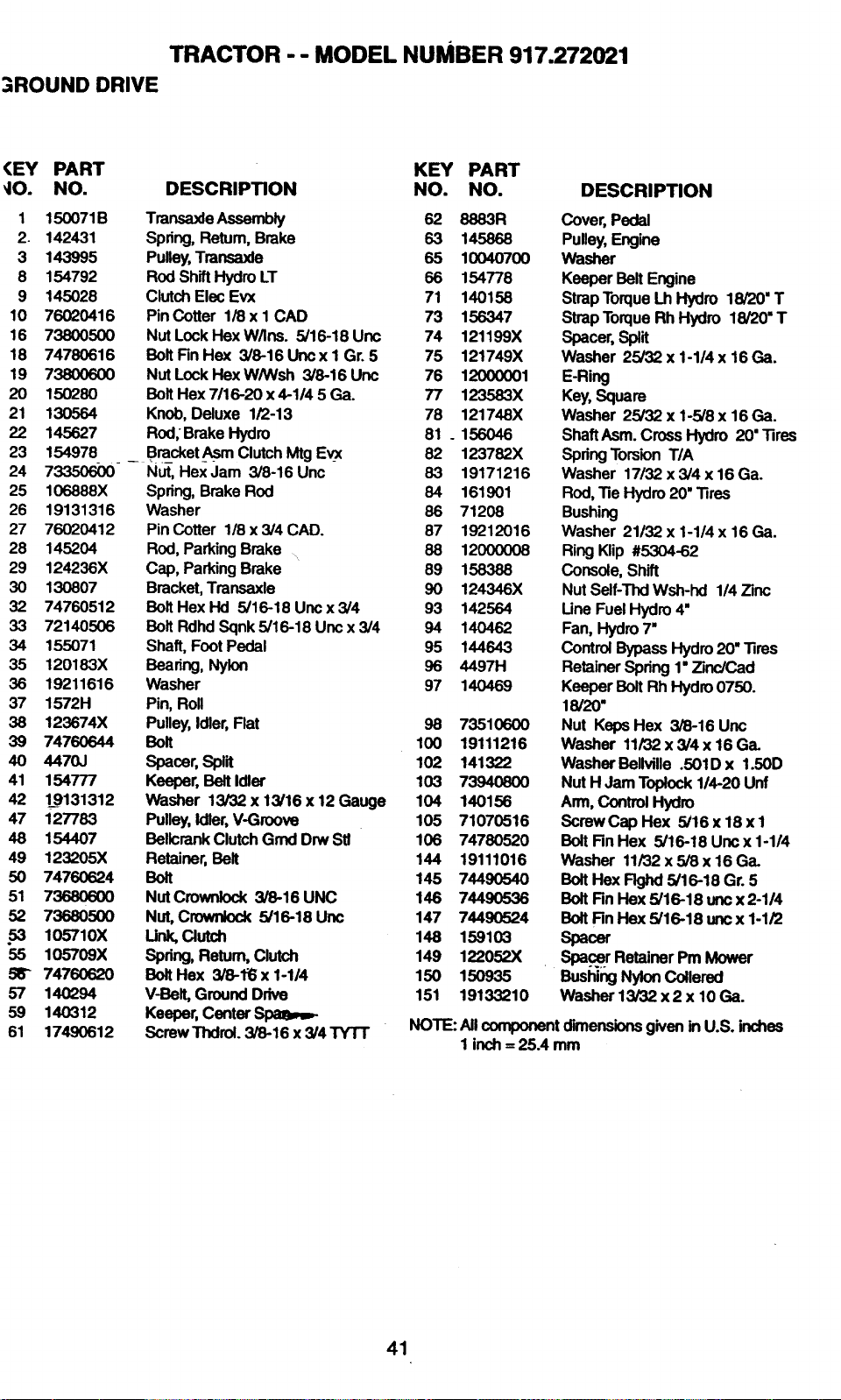
TRACTOR - - MODEL NUMBER 917.272021
. ROUND DRIVE
(EY PART KEY PART
_10. NO. DESCRIPTION NO. NO.
1
2.
3
8
9
10
16
18
19
20
21
22
23
24
25
26
27
28
29
3O
32
33
34
35
35
37
38
39
40
41
42
47
48
49
5O
51
52
.53
55
56"
57
59
61
150071B
142431
143995
154792
145028
76020416
73800500
74780616
738OO6OO
150280
130564
145627
TransaxleAssembly
Spring,Retum,Brake
Pulley,Transaxle
RodShiftHydroLT
ClutchElecEvx
PinCotter 1/8x I CAD
NutLockHexW/Ins. 5/16-18 Unc
BoltFinHex 3/8-16 Uncx I Gr.5
NutLockHexW/Wsh 3/8-16 Unc
BoltHex7116-20x 4-1145 Ga.
Knob,Deluxe 1/2-13
Rod,BrakeHydro
154978
73350600
106888X
19131316
76020412
145204
124236X
130807
74760512
72140506
155071
120183X
19211616
1572H
123674X
74760644
4470J
154777
1_9131312
127783
154407
123205X
74760624
73680600
73680500
105710X
105709X
74760620
140294
140312
17490612
__ Bra_cket_ Clutch Mtg Evx
NUt, Hex Jam 3/8-16 Unc
Spring, Brake Rod
Washer
Pin Cotter 1/8 x 3/4 CAD.
Rod, Parking Brake _,.
Cap, Parking Brake
Bracket, Transaxle
Bolt Hex Hd 5/16-18 Unc x3/4
Bolt Rdhd Sqnk 5/16-18 Unc x 3/4
Shaft, Foot Pedal
Bearing,Nyk_n
Washer
Pin, Roll
Pulley, Idler, Flat
Bolt
Spacer,Spilt
Keeper, Belt Idler
Washer 13/32 x 13/16 x 12 Gauge
Pulley, Idler, V-Groove
Bellcrank Clutch Grnd Drw Stl
Retainer, Belt
Bolt
Nut Crownlock 3/8-16 UNC
Nut, Crownlock 5/16-18 Unc
Unk,Clutch
Spring, Return, Clutch
BoltHex 3/8-1_ x 1-114
V-Bolt, Ground Drive
Keeper, Center
Screw Thdrol. 3/8-16 x 3/4 TYTT
DESCRIPTION
62 8883R
63 145868
65 10040700
66 154778
71 140158
73 156347
74 121199X
75 121749X
76 12000001
77 123583X
78 121748X
81 o 156046
82 123782X
63 19171216
84 161901
86 71208
87 19212016
88 12000008
89 158388
90 124346X
93 142564
94 14O462
95 144643
96 4497H
97 140469
98 73510600
100 19111216
102 141322
103 73940800
104 140156
105 71070516
106 74780520
144 19111016
145 74490540
146 74490536
147 74490524
148 159103
149 122052X
150 150935
151 19133210
Cover, Pedal
Pulley, Engine
Washer
Keeper Belt Engine
Strap Torque Lh Hydro 18/20" T
Strap Torque Rh Hydro 18/20" T
Spacer, Split
Washer 25/32 x 1-1/4 x 16 Ga.
E-Ring
Key, Square
Washer 25/32 x 1-5/8 x 16 Ga.
ShaftAsm. Cross Hydro 20" .Rres
Spring Torsion T/A
Washer 17132 x 3/4 x 16 Ga.
Rod, "ReHydro 20" "Rres
Bushing
Washer 21132 x 1-1/4 x 16 Ga.
Ring Klip #5304-62
Console, Shift
Nut Self-Thd Wsh-hd 1/4 Zinc
Une Fuel Hydro 4"
Fan, Hydro 7"
Control Bypass Hydro 20" "Rres
Retainer Spring 1" Zinc/Cad
Keeper Bolt Rh Hydro 0750.
18/20"
Nut Keps Hex 3/8-16 Unc
Washer 11/32 x 3/4 x 16 Ga.
Washer Beliville .501D x 1.50D
Nut H Jam Toplock 114-20 Unf
Arm, Control Hydro
ScrewCap Hex 5/16x 18xl
Bolt Rn Hex 5/16-18 Uncx 1-1/4
Washer 11/32 x 5/8 x 16 Ga.
BoltHex Flghd 5/16-18 Gr. 5
BoltRn Hex 5/16-18 uricx 2-114
BoltRn Hex 5/16-18 unc x 1-1/2
spacer
Spa.ce.r Retainer Pm Mower
Bushing Nylon Collered
Washer 13/32 x2 x 10Ga.
NOTE: All component dimensions given in U.S. inches
1 inch = 25A mm
41
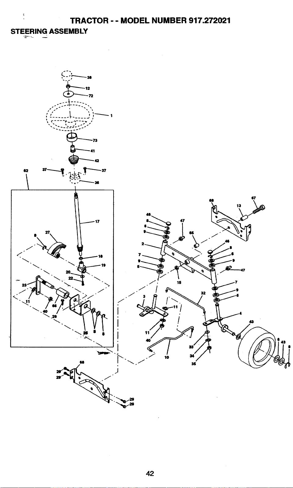
TRACTOR - - MODEL NUMBER 917.272021
STEERING ASSEMBLY
• i
47
68
13
67
4,1
42
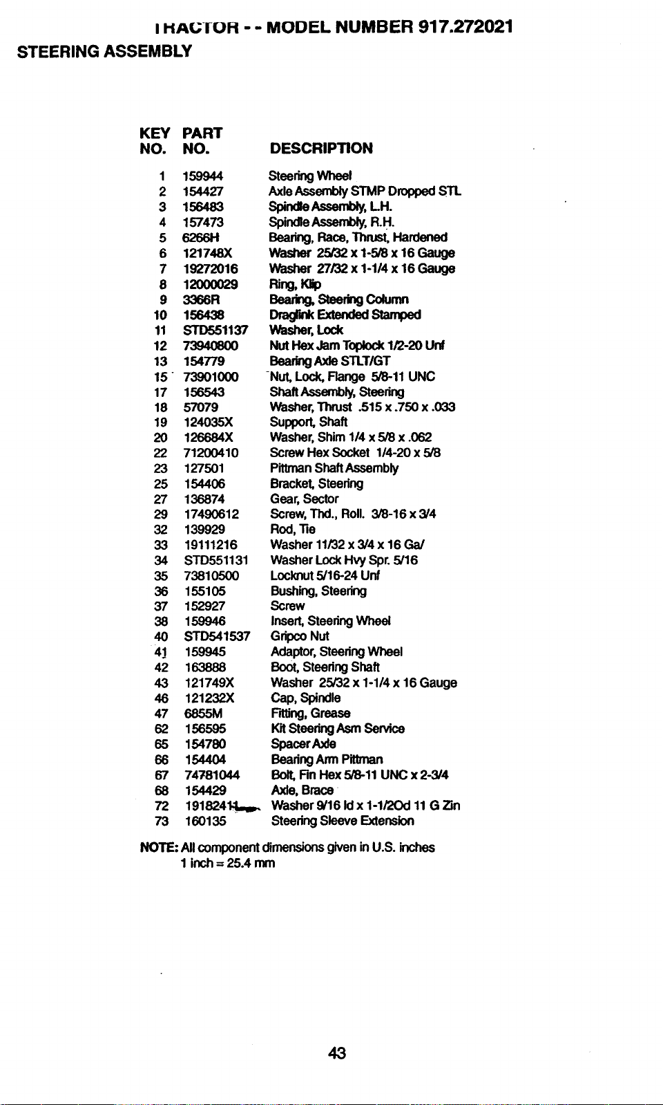
I HAIL;-IUH - - MODEL NUMBER 917.272021
STEERING ASSEMBLY
KEY PART
NO. NO. DESCRIPTION
1 159944
2 154427
3 156483
4 157473
5 62661-1
6 121748X
7 19272016
6 12000029
9 3366R
10 156438
11 STD551137
12 7"3940800
13 154779
15 739010(X)
17 156543
18 57079
19 124035X
20 126584X
22 71200410
23 127501
25 154406
27 136874
29 17490612
32 139929
33 19111216
34 STD551131
35 73810500
36 155105
37 152927
38 159946
40 STD541537
41 159945
42 163888
43 121749X
46 121232X
47 6855M
62 156595
65 154780
66 154404
67 74781044
68 154429
72 191824N.1_
73 160135
SteeringWheel
Axle Assembly STMP Dropped STL
Spindle Assembly, LH.
Spindle Assembly, R.H.
Bearing,Race,Thrust,Hardened
Washer 25/32 x 1-5/8 x 16 Gauge
Washer 27/32 x 1-1/4 x 16 Gauge
PJng,K_p
Bea_ Stee_ngCo_mn
Dragr._ExtendadStaraped
Washer, Lock
Nut Hex Jam Topk>ck1/2-20 Unf
Bearing Axle STLT/GT
-Nut, Lock, Flange 5/8-11 UNC
ShaftAssembly,Steedng
Washer, Thrust .515 x .750 x .033
Support, Shaft
Washer, Shim 1/4 x5/8 x .062
Screw Hex Socket 1/4-20 x 5/8
Pittrnan Shaft Assembly
Bracket, Steering
Gear, Sector
Screw, Thd., Roll. 3/8-16 x 3/4
Rod, "Re
Washer 11/32 x 3/4 x 16 Ga/
Washer Lock Hvy Spr. 5/16
Locknut 5/16-24 Unf
Bushing, Steering
Screw
Insert, Steering Wheel
Gdpco Nut
Adaptor, Steering Wheel
Boot, Steedng Shaft
Washer 25/32 x 1-1/4 x 16 Gauge
Cap, Spindle
F'_lJng,Grease
KitSteeringAsmSen/ice
Spacer Axle
Bearing Arm Pittman
Bolt, Rn Hex 5/8-11 UNC x 2-3/4
Axle, Brace
Washer 9/16 Id x 1-1/20d 11 G Zin
Steering Sleeve Extension
NOTE: AllcomponentdimensionsgiveninU.S. inches
1 inch= 25.4 mm
43
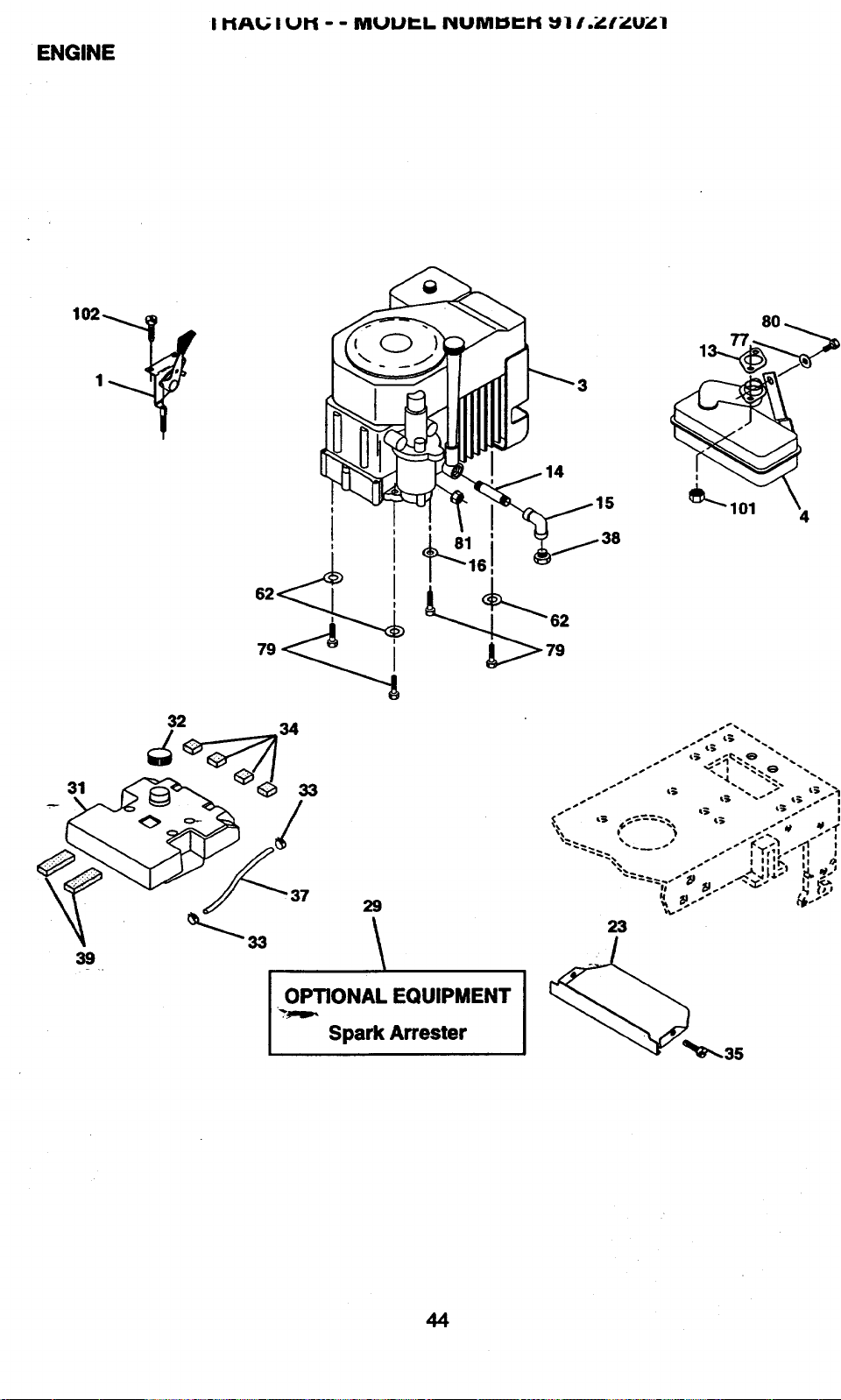
ENGINE
I hAL; I Ul'i - - MUUr-. II PIUMIDI"I-I _l I._..'r_.U_.l
14
8O
_L"_ 101 4
39
29
OPTIONAL EQUIPMENT
%.,mm,.
Spark Arrester
_ _ _" I Yr _l-J I I
23
44
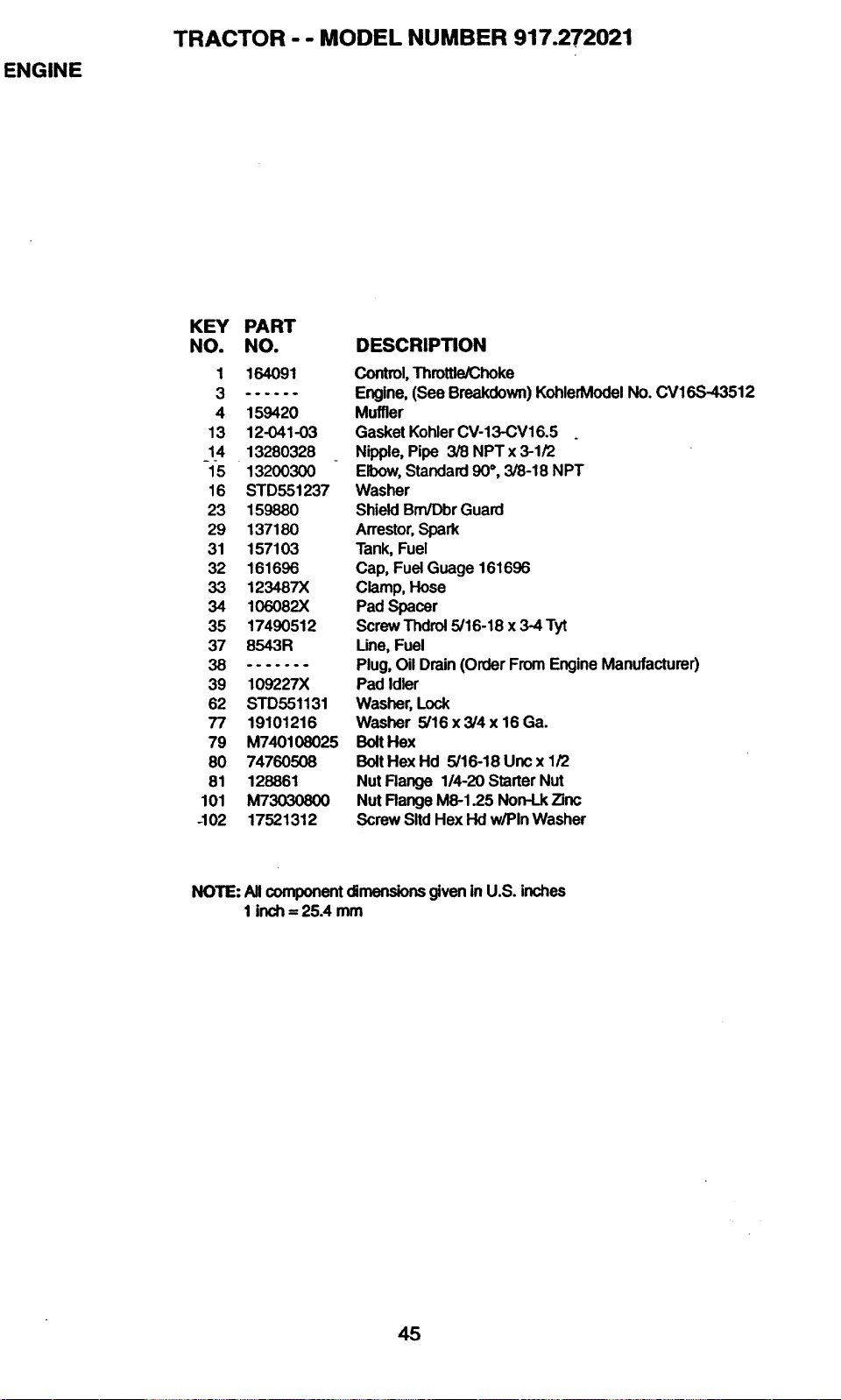
ENGINE
TRACTOR -- MODEL NUMBER 917.272021
KEY PART
NO. NO.
1 164091
......
4 159420
13 12-041-03
14 13280328
15 13200300
16 STD551237
23 159880
29 137180
31 157103
32 161696
33 123487X
34 106082X
35 17490512
37 8543R
8 .......
39 109227X
62 STD551131
77 19101216
79 M740108025
80 74760508
81 128861
101 M73030800
-102 17521312
DESCRIPTION
Control, Throttle/Choke
Engine, (See Breakdown) KohlerModel No. CV16S-43512
Muffler
Gasket Kohler CV-13-CV16.5
Nipple, Pipe 3/8 NPT x 3-1/2
Elbow, Standard 90°, 3/8-18 NPT
Washer
Shield Brn/Dbr Guard
Arrestor, Spark
Tank, Fuel
Cap, Fuel Guage 161696
Clamp, Hose
Pad Spacer
Screw Thdrol 5/16-18 x 3-4 Tyt
Une, Fuel
Plug, Oil Drain (Order From Engine Manufacturer)
Pad Idler
Washer, Lock
Washer 5/16 x 3/4 x 16 Ga.
Bolt Hex
Bolt Hex Hd 5/16-18 Unc x 1/2
Nut Range 1/4-20 Starter Nut
Nut Flange M8-1.25 Non-Lk Zinc
Screw Sltd Hex Hd w/Pin Washer
NOTE: AllcomponentdimensionsgNeninU.S. inches
1inch= 25A mm
45
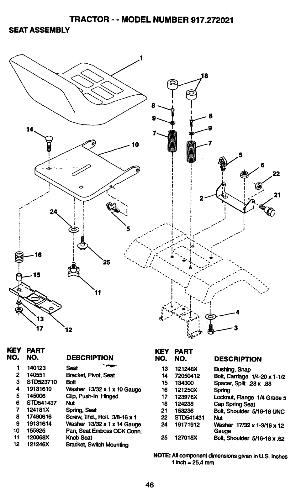
TRACTOR - - MODEL NUMBER 917.272021
SEAT ASSEMBLY
14
I
f
i
;
' I
16
12
18
ir
I
!
I °
°
I
i
I
i
I
°
I °
!
I ' I
0
I
i
5 6
I
21
KEY PART
NO. NO.
1 140123
2 140551
3 STD523710
4 19131610
5 145006
6 STD541437
7 124181X
8 17490616
9 19131614
10 155925
11 120068X
12 121246X
DESCRIPTION
Seat _"_'
Bracket,Pivot,Seat
Bolt
Washer 13/32x I x 10 Gauge
Clip,PusPPlnHinged
Nut
Spring,Seat
Screw,Thd.,Roll. 3/8-16 x 1
Washer 13/32x 1 x 14Gauge
Pan,Seat EmbossQCK Conn.
KnobSeat
Bracket,SwitchMounting
KEY PART
NO. NO. DESCRIPTION
13 121248X Bushing, Snap
14 72050412 Bolt, Carriage 1/4-20 x 1-1/2
15 134300 Spacer, Split .28 x .88
16 121250X Spring
17 123976X Locknut, Flange 1/4 Grade 5
18 124238 Cap Spring Seat
21 153238 Bolt, Shoulder 5/16-18 UNC
22 STD541431 Nut
24 19171912 Washer 17/32 x1-3/16 x12
Gauge
25 127018X Bolt, Shoulder 5/16-18 x.62
NOTE: NI component dimensions given in U.S. inches
1 inch = 25.4 mm
46

DECALS
TRACTOR - - MODEL NUMBER 917.272021
11
KEY PART
NO. NO.
1 164O94
2 106202X
3 163916
4 163917
5 164088
6 133644
7 163263
8 163203
9 163204
10 156439
11 142341
21 13 6
3
14
16
5
8
KEY PART
DESCRIPTION NO. NO.
Decal, Dash, Stealth 12 146046
Reflector Tail Light 13 164065
Decal, Hood, R.H. 14 160397
Decal, Hood, L.H. 16 138047
Decal Brake Clutch Stealth 20 149516
Decal, Customer Maintenance 21 163206
Decal Dash Pnl Kohler -- 138311
Decal, Deck Mower EZ - - 154515
Decal, Fender, Craftsman -- 154516
Decal, Fender Danger -- 165060
Decal, Drawbar Cntd Mvt Hyd Lt - - 165061
1
7
21
12
DESCRIPTION
Decal, V-Belt Drive Schematic
DacalStrgWhe_
Decal, V-Belt Schematic
Decal, Battery Diehard
Decal, Battery Dngr/Psn Eng
Decal, Fender Side
Decal, Lift Handle
Pad Footrest LH STLT
Pad Footrest RH STLT
Owner's Manual, English
Owners Manual, Spanish
WHEELS & TIRES
7
11
KEY PART
NO. NO. DESCRIPTION
1 59192 Valve Cap, Tire
2 65139 Stem, Valve
3 106222X Tire, Front
4 59904 Tube, Front'nre
(NotProvided,Sen4ceHemOrdy)
5 106732X427 Rim, Front
6 278H Fitting,Grease (Front Wheel Only)
7 9040H Bearing, Range (Front Wheel Only)
8 106108X427 Rim, Rear
9 122082X Tire, Rear
10 7152J Tube, RearTire
(NotProvided,SmvicettemOrdy)
11 104757X Cap, Axle
-- 144334 Sealant, Tire 10 oz.
No'rE:Alloompon_ d_a_ls gk'enInU.S._s
1 inch = 25.4 mm
47

, n_v evn - - Muur..L PlUMUI:.I"[ _] 7'.272021
LIFT ASSEMBLY
27
25 24
23
7
8
/
2O
48
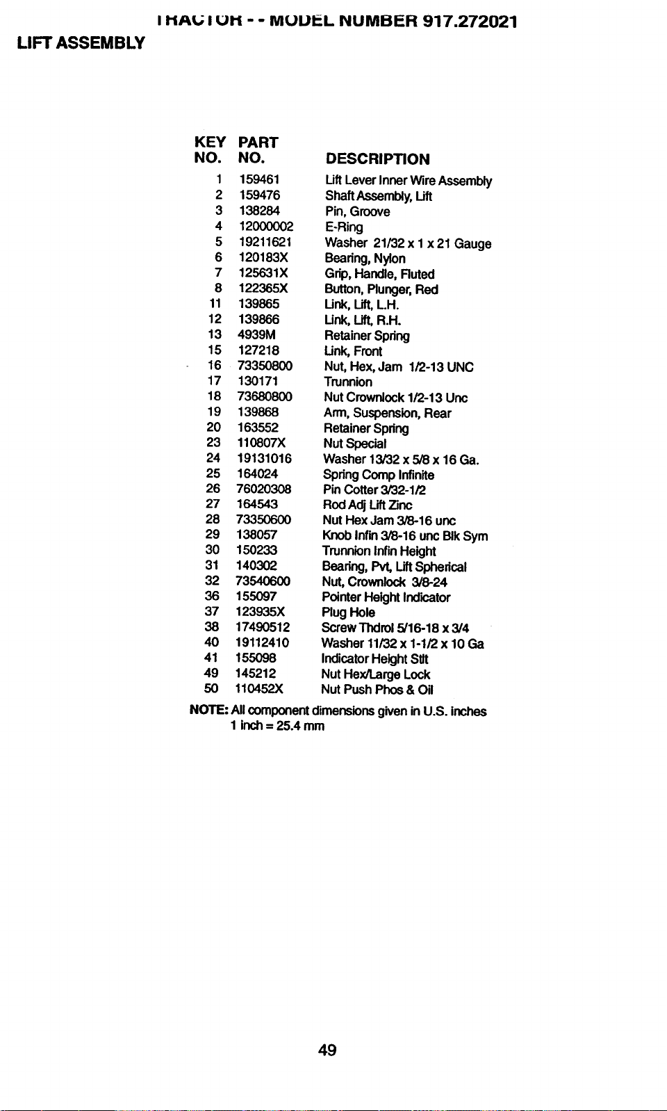
I HAt.; I UH - - MUU_L NUMBER 917.272021
LIFT ASSEMBLY
KEY PART
NO. NO. DESCRIPTION
1 159461 Lift Lever Inner Wire Assembly
2 159476 Shaft Assembly, Lift
3 138284 Pin, Groove
4 12000002 E-Ring
5 19211621 Washer 21/32 x I x 21 Gauge
6 120183X Bearing, Nylon
7 125631X Grip, Handle, Ruted
8 122365X Button, Plunger, Red
11 139865 Link, Lift, LH.
12 139866 Link, Lift, R.H.
13 4939M Retainer Spring
15 127218 Link, Front
16 73350800 Nut, Hex0Jam 1/2-13 UNC
17 130171 Trunnion
18 73680800 Nut Crownlock 1/2-13 Unc
19 139868 Arm, Suspension, Rear
20 163552 Retainer Spring
23 110807X NutSpecial
24 19131016 Washer 13/32 x 5/8 x 16 Ga.
25 164024 Spring Comp Infinite
26 76020308 Pin Cotter 3/32-1/2
27 164543 RodAdj LiftZinc
28 73350600 Nut Hex Jam 3/8-16 unc
29 138057 Knob Infin 3/8-16 unc BIk Sym
30 150233 Trunnion InfinHeight
31 140302 Bearing, Pvt' Lift Spherical
32 73540600 Nut, Crownlock 3/8-24
36 155097 Pointer Height Indicator
37 123935X Plug Hole
38 17490512 ScrewThdrol 5/16-18 x3/4
40 19112410 Washer 11/32 x 1-1/2 x 10 Ga
41 155098 Indicator Height stir
49 145212 Nut Hex/Large Lock
50 110452X Nut Push Phos & Oil
NOTE: AllcomponentdimensionsgiveninU.S. inches
1 inch= 25.4 mm
49
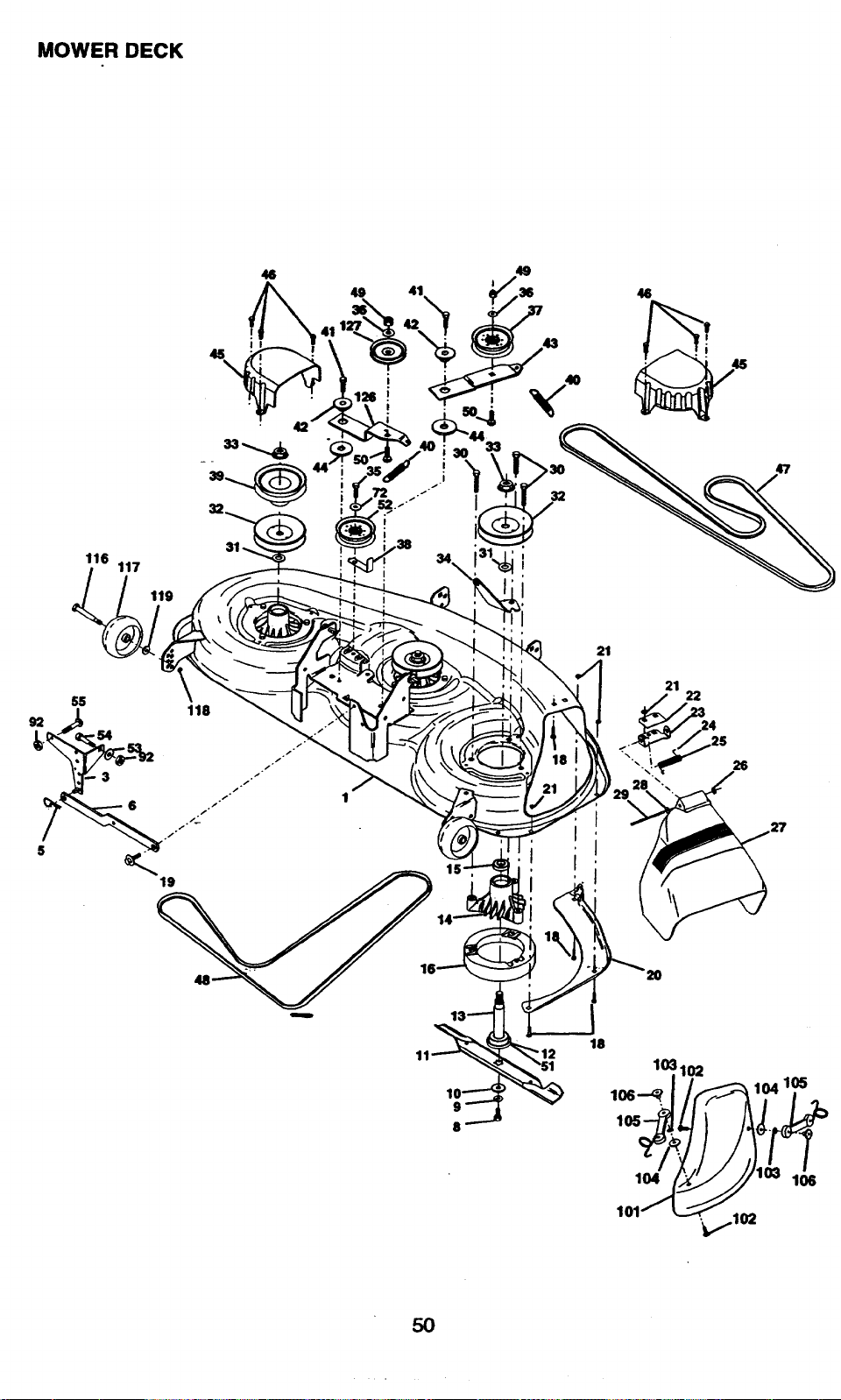
MOWER DECK
46
49
126 !
!
116
117
119
34
21
21
24
2S
26
9
8
18
103102
106--_
106
104
101
106
5O
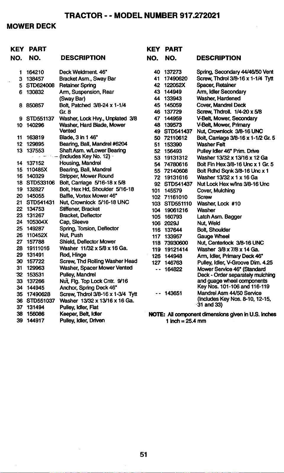
TRACTOR - - MODEL NUMBER 917.272021
MOWER DECK
KEY PART KEY PART
NO. NO. DESCRIPTION NO. NO. DESCRIPTION
1 164210 Deck WeldmenL 46" 40 137273
3 138457 Bracket Asm., Sway Bar 41 17490620
5 STD624008 Retainer Spring 42 122052X
6 130832 Arm, Suspension, Rear 43 144949
(Sway Bar) 44 133943
8 850857 Bolt, Patched 3/8-24 x 1-1/4 45 145059
Gr. 8 46 137729
9 STD551137 Washer, Lock Hvy., Unplated 3/8 47 144959
10 140296 Washer, Hard Blade, Mower 46 139573
Vented 49 STD541437
11 163819 Blade, 3 in I 46" 50 72110612
12 129895 Beadng, BaU,Mandrel#6204 51 153390
13 137553 Shaft Asm. w/Lower Bearing 52 156493
....... (Includes Key No. 12) - 53 19131312
14 137152 Housing, Mandrel 54 74780616
15 110485X Bearing, Ball, Mandrel 55 72140608
16 140329 Stripper, MowerRound 72 19131616
18 STD533103 Balt, Cardage 5/16.18x5/8 92 STD541437
19 132827 Bolt, Hex Hd, Shoulder 5/16-18 101 145579
20 145055 Baffle, Vortex Mower46" 102 71161010
21 STD541431 Nut, Crownlock 5/16-18 UNC 103 STD551110
22 134753 Stiffener, Bracket 104 19061216
23 131267 Bracket, Deflector 105 160793
24 105304X Cap, Sleeve 106 2029J
25 149287 Spring, Torsion, Deflector 116 137644
26 110452X Nut, Push 117 133957
27 157788 Shield, DeflectorMowar 118 73930600
28 19111016 Washer 11/32 x 5/8 x 16 Ga. 119 19121414
29 131491 Rod, Hinge 126 144948
30 157722 Screw, Thd Rolling Washer Head 127 146763
31 129963 Washer, Spacer Mower Vented - - 164822
32 153531 Pulley, Mandrel
33 137266 Nut, Fig. Top Lock Cntr. 9/16
34 144945 Anchor, Spring Deck 46"
35 17490628 Screw, Thdrol 3/8-16 x 1-3/4 Tytt - - 143651
36 STD551037 Washer 13/32 x 13/16 x 16 Ga.
37 131494 Pulley, Idler, Flat
38 156086 Keeper, Belt, Idler
39 144917 Pulley, Idler, Driven
Spring,Secondary44/46/50 Vent
Screw,Thdrol3/8-16 x 1-1/4 Tytt
Spacer,Retainer
Arm,IdlerSecondary
Washer,Hardened
Cover,MandrelDeck
Screw,Thdroll. 114-20x 5/8
V-Belt,Mower,Secondary
V-Belt,Mower,Primary
Nut,Crownlock3/8-16UNC
Bolt,Carriage3/8-16x 1-1/2Gr.5
WasherFelt
PulleyIdler46" Prim.Drive
Washer13/32 x 13/16x 12 Ga
BoltFinHex3/8-16Uncx I Gr.5
BoltRdhdSqnk3/8-16 Uncx 1
Washer13/32x 1 x 16 Ga
NutLockHexw/Ins3/8-16Unc
Cover,Mulching
Screw
Washer,Lock #10
Washer
LatchAsm.Bagger
Nut,Weld
Bolt,Shoulder
GaugeWheel
Nut,Centerlock3/8-16 UNC
Washer 3/8x 7/8x 14Ga.
Arm,Idler,PrimaryDeck46"
Pulley,Idler,V-GrooveDim.4.25
MowerService46"(Standard
Deck- Orderseparatelymulching
andguagewheelcomponents
KeyNos.101-106and 116-119
MandrelAsm44/50 Service
(includesKeyNos.8-10, 12-15,
•31 and 33)
NOTE: AllcomponentdimensionsgiveninU.S. Inches
1 inch= 25A mm
51
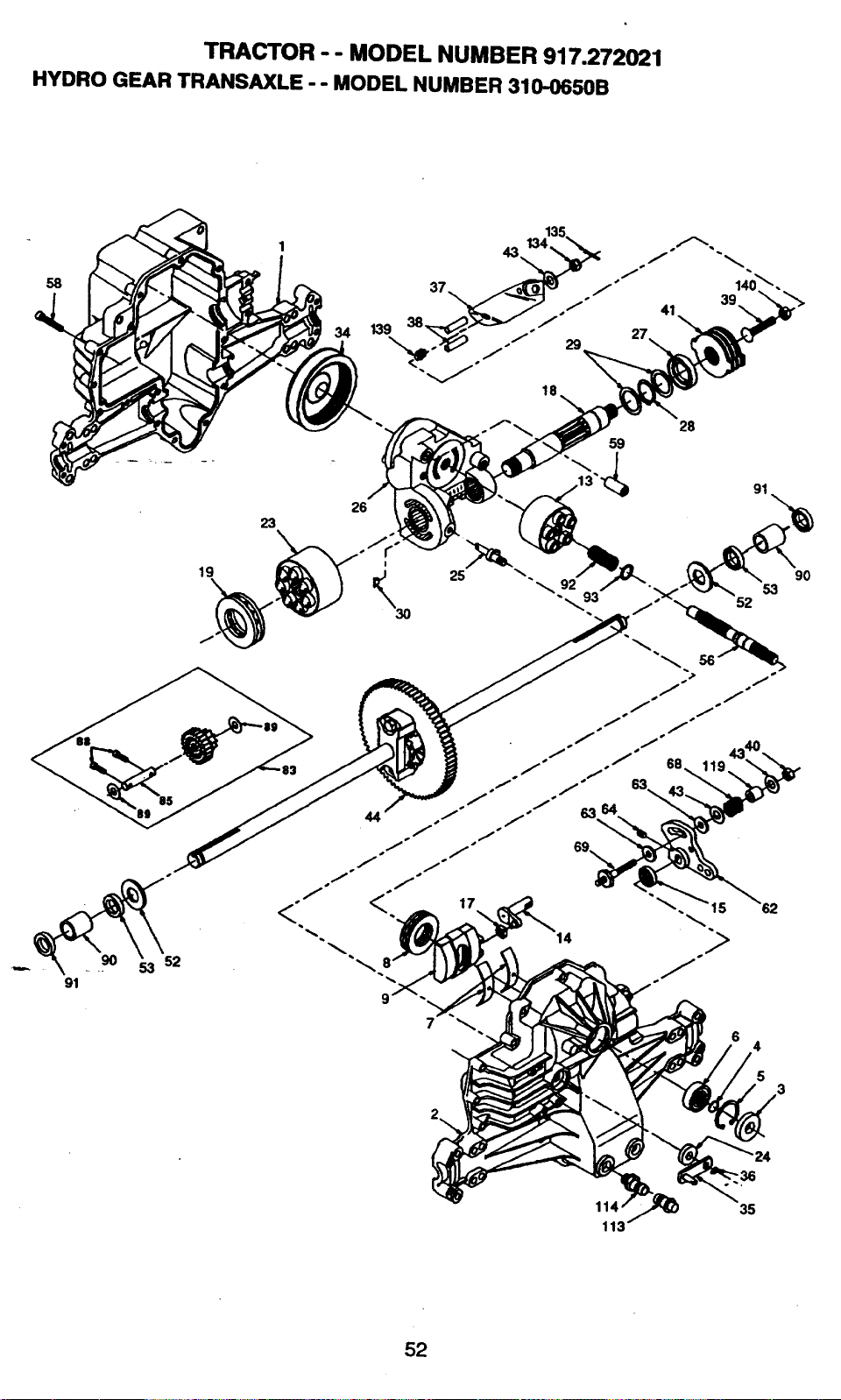
TRACTOR - - MODEL NUMBER 917.272021
HYDRO GEAR TRANSAXLE - - MODEL NUMBER 310-0650B
58
34 139
91
52
19
26
28
59
91
17
14
5
3
'36
35
113
52

TRACTOR - - MODEL NUMBER 917.272021
HYDRO GEAR TRANSAXLE - - MODEL NUMBER 310-0650B
KEY PART KEY PART
NO. NO. DESCRIPTION NO. NO.
1 142930 Housing, Lower 43 142884
2 142931 Assembly, Upper Housing 44 150829
3 142932 Seal, Up 52 142991
4 142928 Ring, Wire Retaining 53 142961
5 142933 Ring, Retaining 56 142963
6 142934 Bearing, Shaft Ball 56 142964
7 142935 Bearing, Cradle 59 142965
8 150771 Bearing, Thrust 30x52x13 62 142966
9 142937 Swashplate, Variable 63 142967
13 142938 Block, Cylinder Assembly 64 142920
14 142_93_9 Arm, Trunnion 68 142969
15 142940 Seal, Lip 69 144610
17 142941 Guide, Slot 83 142971
18 150772 Shaft, Motor 85 150806
19 150773 Bearing, Thrust 42x68x16 68 142973
23 142944 Block, Cylinder Assembly 89 142974
24 142945 Seal, Lip 10x25x7 90 142975
25 142946 Actuator, Bypass 91 142976
26 150774 Center Section Assembly Kit 92 142977
27 142948 Seal, Lip 26 x 42 x 8 93 142978
28 142949 Ring, Retaining 113 142917
29 142950 Washer 26x35x I 114 142918
30 150787 Plate, Bypass 119 142980
34 142951 Oil Rlter Element 134 144507
35 142952 Arm, Bypass 135 144608
38 142953 Ring, Retaining 139 150775
37 142954 Arm, Actuating 140 150776
38 142955 Pin, Actuating
39- 150777 Bolt 5/16-24 x 1-3/4 NOTE:
40 150778 Leclmut, Hex 5/16-24 UNJC
41 142956 Brake Rotor/Stator l_t
DESCRIPTION
Washer 7/16 x 7/8 x .060
DifferentialAssembly
Washer 3/4 x 1.5 x. 13
Seal .75 x 1.25 x 2.50
Shaft, Input
Bolt 1/4-20 x 1.38
Pin .50D x .43 ID x .750
Arm, Control
Puck, Dampener
Set Screw
Spring
Stud 5/16-24
Jackshaft Assembly
Jackshaft
Screw, Cap
Washer 7/16 x I x 1/2
Sleeve Bearing
Seal, Wiper
Spdng, Block
Washer, BlockThrust
Cap,VentAssembly
Fitting, O-Ring Assembly
Spacer
Nut, Castle 5/16-24
Pin, Cotter
sp_ng,Compres_n
Nut, Hex 5/16-24
AllcomponentdimensionsgiveninU.S.
inchesI inch= 25A mm
53
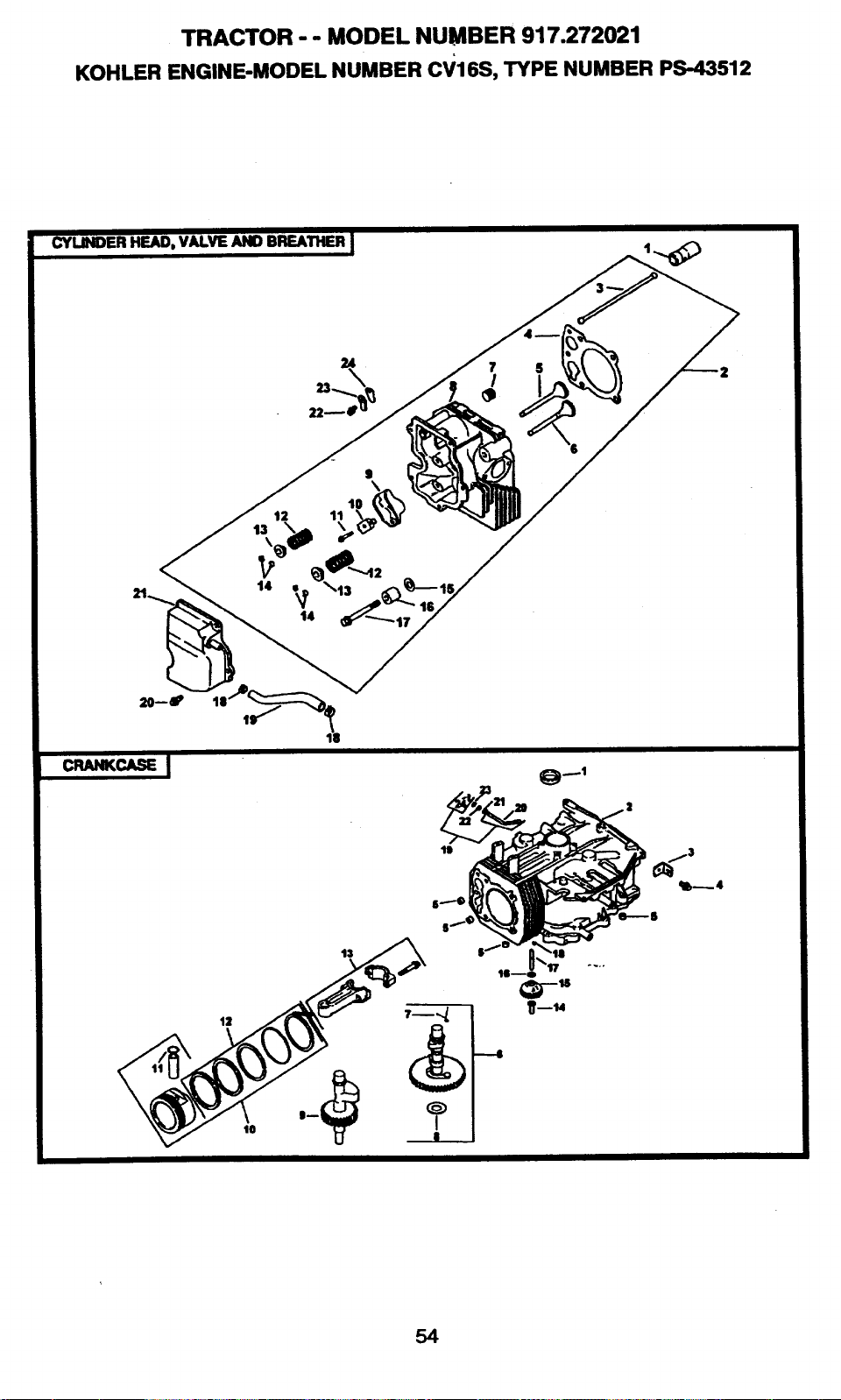
TRACTOR-- MODEL NUMBER 917.272021
KOHLER ENGINE-MODEL NUMBER cV16S, TYPE NUMBER PS-43512
CYLINDER HEAD, VALVE AND BREATHER I
7
/
t2 11
\
t4
12
lO
13
----4
e6_4
54
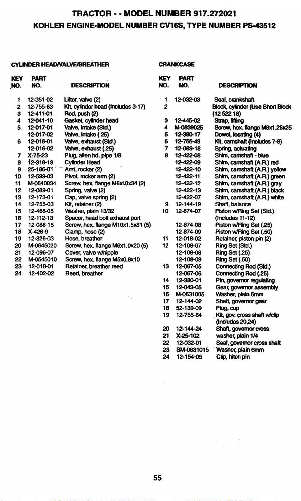
TRACTOR - - MODEL NUMBER 917.272021
KOHLER ENGINE-MODEL NUMBER CV16S, TYPE NUMBER PS-43512
CYUNDER HEAD/VALVE/BREATHER
KEY PART
.NO. NO.
CRANKCASE
1 12-351-02
2 12-755-63
3 12411-01
4 12-041-10
5 12-017-01
12-017-02
6 12-016-01
12-016-02
7 X-75-23
8 42-318-19
9
10 12-599-03
11 M-0640034
12 12-089-01
13 12-173-01
14 12-755-03
15 12-468-05
16 12-112-13
17 12-086-15
18 X-426-9
19 12-326-03
20 M-0645020
21 12-096-07
22 M-0545010
23 12-018-01
24 i2-402.O2
KEY PART
DESCRIPTION NO. NO.
Lifter,valve(2)
Kit, cylinder head (Includes 3-17)
Rod,push(2)
Gasket,cylinderhead
Vak,e,intake(Std.)
va_,e,_ake(.25")
Valve,exhaust (S_L)
yak,e,exhaust(25)
Plug, allen hd. pipe 1/8
CyUnderHead
25-186-O1.... Arn_,-rocker(2)
Pivot, rocker arm (2)
Screw, hex. flange M6xl.0x34 (2)
Spring,vaJve(2)
Cap,valvespring(2)
Kit, retainer (2)
Washer, plain 13/32
Spacer, head bolt exhaust port
Screw, hex. flange M10x1.5x81 (5)
Clamp, hose (2)
Hose, breather
Screw, hex. flange M6xl.0x20 (5)
Cover, valve w/nipple
Screw, hex. flange M5xO.8xlO
Retainer, breather reed
Reed, breather
1 12032-03
2
3 12-445-02
4 M-0839025
5 12-380-17
6 12-755-49
7 12-089-18
8 12-422-08
12-422-09
12-422-10
12-422-11
12-422-12
12-422-13
12-422-07
9 12-144-19
10 12-874-07
12-874-08
12-874-09
11 12-018-O2
12 12-108-07
12-108-08
12-108-09
13 12-067-05
12-067-06
14 12-380-01
15 12-043-05
16 M-0631005
17 12-144-02
18 52-139-09
19 12-755-64
20 12-144-24
21 X-25-102
22 12-032-01
23 SM-0631015
24 12-154-05
DEsca.qlo.
Seal,_
ak_, _ (UseShortBock
(12 522 18)
strap,rang
Screw,hex:ghangeMSxl_)x2S
Dow_k)caUng(4)
10t,camsh_ (includes 7-8)
sp_g, act.aung
Shim, camshaft - blue
Shim, cemshaft (A.R.) red
Shim,camshaft(A.R.)yellow
Shim, camshaft (A.R.) green
Shim,camshaft(A.R.)gray
Shim,camshaft (A.R.)black
Shim,camshaft (A.R.)white
Shaft, balance
Piston w/Ring Set (Sial.)
(Indudes 11-12)
Piston w/Ring Set (2.5)
Piston w/Ring Set (.50)
Retainer, piston pin (2)
Ring Set (Std.)
Ring Set (2.5)
Ring Set (.50)
connec_ngRod(SU.)
ConnectingRod(2.5)
Pin,governorregu_Ung
Gear,governorassembly
Washer,p_in6n_
Shaft, governor gear
Plug, cup
. Kit,gov.crossshaftw/clip
(indudes2024)
Shaft,govemorcross
washer,plain114
Seal,governorcrossshaft
Washer,p_ainSmm
cl_, hitchpin
55
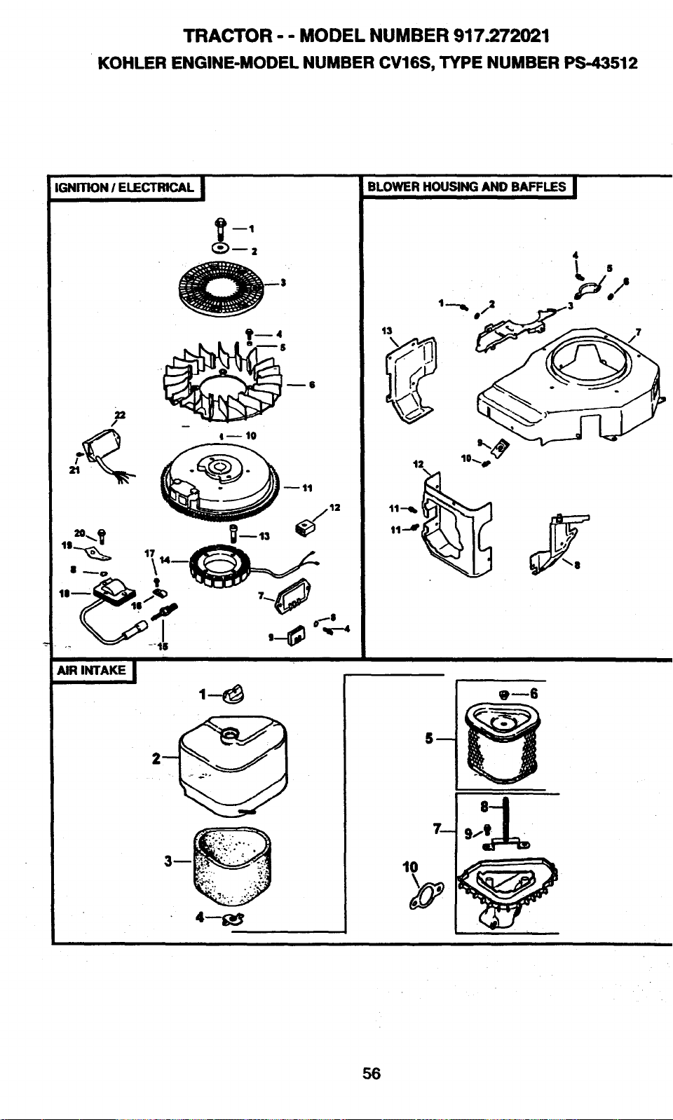
TRACTOR - - MODEL NUMBER 917.272021
KOHLER ENGINE-MODEL NUMBER CV16S, TYPE NUMBER PS-43512
IGNITION I ELECTRICAL
1+--4
AIR INTAKE I
4--1;_
BLOWER HOUSING AND BAFFLES I
13
1
---,.
9--6
56
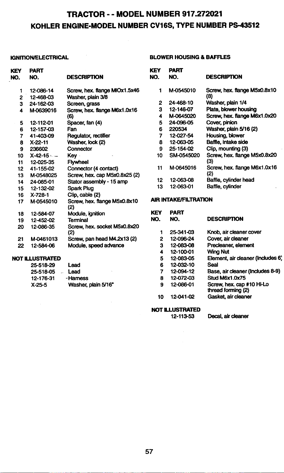
TRACTOR - - MODEL NUMBER 917.272021
KOHLER ENGINE-MODEL NUMBER CV16S, TYPE NUMBER PS-43512
IGNmON/ELECTRICAL
KEY PART
NO. NO. DESCRIPTION
1 12-086-14
2 12-468-03
3 24-162-03
4 M-0639016
5 12-112-01
6 12-157-03
7 41-403-09
8 X-22-11
9 236602
10 X-42-1-5 ....
11 12-025-35
12 41-155-02
13 M-0548025
14 24-085-O1
15 12-132-02
16 Xo728-1
17 M-0545010
18 12-584-07
19 12-452-02
20 12-086-35
21 M-0461013
22 12-584-06
Screw, hex. flange MIOx1.5x46
Washer, plain 3/8
Screen, grass
Screw, hex. flange M6x1.0x16
(6)
Spacer, fan (4)
Fan
.Regulator, rectifier
Washer, lock (2)
Connector
Key
Flywheel
Connector (4 contact)
Screw, hex. cap MSx0.8x25 (2)
Stator assembly - 15 amp
Spark Plug
Clip, cable (2)
Screw, hex. flange M5x0.8xl0
(2)
Module, ignition
Terminal
Screw, hex. socket M5x0.8x20
(2)
Screw, pan head M4.2x13 (2)
Module, speed advance
NOT ILLUSTRATED
25-518-29
25-518-05 --
12-176-31
X-25-5
Lead
Lead
-Harness
Washer, plain 5/16"
BLOWER HOUSING & BAFFLES
KEY PART
NO. NO. DESCRIPTION
1 M-0545010 Screw, hex. flange M5x0.8xl0
(s)
2 24-468-10 Washer, plain 1/4
3 12-146-07 Plate, blower housing
4 M-0645020 Screw, hex. flange M6xl.0x20
5 24-096-05 Cover, pinion
6 220534 Washer, plain 5/16 (2)
7 12-027-54 Housing, blower
8 12-063-05 Baffle, intake side
9 25-154-02 Clip, mounting (3)
10 SM-0545020 Screw, hex. flange M5x0.8x20
(3)
11 M-0645016 Screw, hex. flange M6x1.0x16
(2)
12 12-063-08 Baffle, cylinder head
13 12-063-01 Baffle, cylinder
AIR INTAKE/FILTRATION
KEY PART
NO. NO. DESCRIPTION
1 25-341-03 Knob, air cleaner cover
2 12-096-24 Cover, air cleaner
3 12-083-08 Precleaner, element
4 12-100-01 Wing Nut
5 12-083-05 Element, air cleaner (Includes 6',
6 12-032-10 Seal
7 12-094-12 Base, air cleaner (Includes 8-9)
8 12-072-03 Stud M6x1.0x75
9 12-086-01 Screw, hex. cap #10 Hi-Lo
thread forming (2)
10 12-041-02 Gasket, aircleaner
NOT ILLUSTRATED
12-113-53 Decal,aircleaner
57

TRACTOR - - MODEL NUMBER 917.272021
KOHLER ENGINE-MODEL NUMBER CV16S, TYPE NUMBER PS-43512
STARTING SYSTEM
7----- (_
ENGINECONTROLS
OIL PAN I LUBRICATION I
II ..--10
|
21
58
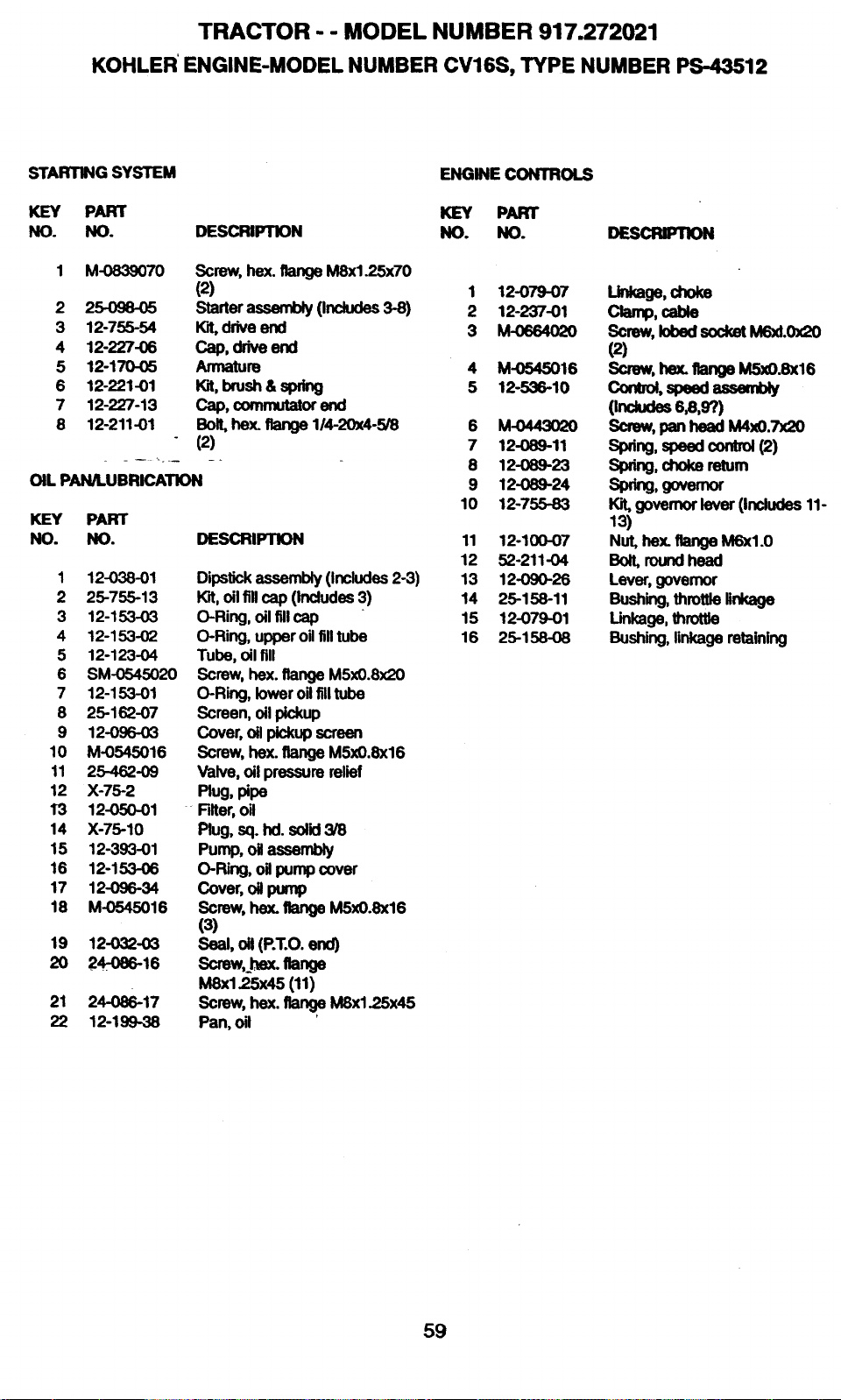
TRACTOR - - MODEL NUMBER 917.272021
KOHLER ENGINE-MODEL NUMBER CV16S, TYPE NUMBER PS-43512
STARTING SYSTEM ENGINE CONTROLS
KEY PART KEY PART
NO. NO. DESCRIPTION NO. NO. DESCRIPTION
1 M-0839070 Screw, he)(. flange M8x1.25x70
(2) 1 12-079-07
2 25-098-05 Starter assembly (Includes 3-8) 2 12-237-01
3 12-755-54 _ drive end 3 M-0664020
4 12-227-06 Cap, drive end
5 12-170-05 Armature 4 M-0545016
6 12-221-01 Wit,brush & spring 5 12-536-10
7 12-227-13 Cap, commu1_or end
e 12-211-01 Bolt, hex. flange 114-20x4-5/8 6 M-0443020
(2) 7 12-089-11
........ 8 12-089-23
OIL PAN/LUBRICATION 9 12-089-24
10 12-755-83
KEY PART
NO. NO. DESCRIPTION 11 12-100-07
12 52-211-04
1 12-038-01 Dipstick assembly (Includes 2-3) 13 12-090-26
2 25-755-13 Kit, oilfillcap (Includes 3) 14 25-158-11
3 12-153-O3 O-Ring, oil fill cap 15 12-079-01
4 12-153-02 O-Ring, upperoil fill tube 16 25-158-08
5 12-123-04 Tube, oil fill
6 SM-0545020 Screw, hex. flange M5x0.8x20
7 12-153-01 O-Ring, lower oil filltube
8 25-162-07 Screen, oil pickup
9 12-096-O3 Cover, oil pickup screen
10 M-0545016 Screw, hex. flange M5x0.8x16
11 25-462-09 Valve, oil pressure relief
12 X-75-2 Plug, pipe
13 12-050-01 +Filter,oil
14 X-75-10 Plug, sq. hd. solid 3/8
15 12-393-01 Pump, oil assembly
16 12-153-06 O-Ring, o'dpump cover
17 12-096-34 Cover, oil pump
18 M-0545016 Screw, hex. flange M5x0.8x16
(3)
19 12-032-03 Seal, oil (P.T.O. end)
2O 24-0e6-16 Screw,l_ex.flange
M8x125x45 (11)
21 24-086-17 Screw, hex. _ MSx1.25x45
22 12-199-38 Pan, oil
linkage,choke
Clamp,cable
Screw, lobed socket M6xL0x20
(2)
Screw, hex, flange M5xO.8x16
como_,speedassembay
(mdudes6_,97)
Screw, pan head M4xO.7x20
Sp_ng,speedcontr_(2)
Slxing,chokereturn
Spring,govemor
Kit, governor lever (Includes 11-
13)
Nut, bex. flange M6xl.0
Bolt,roundhead
Lever, governor
Bosh_g,throt,e,nkage
Linkage, throttle
Bushing, linkage retaining
59
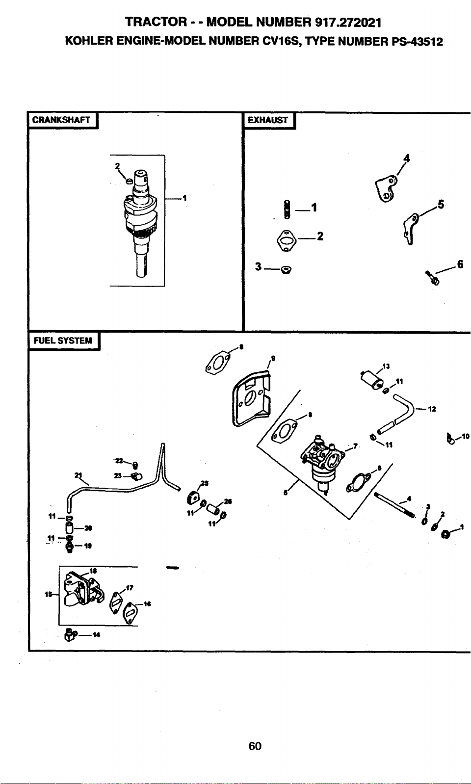
TRACTOR MODEL NUMBER 917.272021
KOHLER ENGINE'MODEL NUMBER CV16S, TYPE NUMBER PS 43512
CRANKSHAFT
¼
EXHAUST I
FUEL SYSTEM
/9
17_
3
,d
60
TRACTOR -- MODEL NUMBER 917.272021
KOHLER ENGINE-MODEL NUMBER CV16S, TYPE NUMBER PS-43512
FUEL SYSTEM
KEY PART
NO. NO.
1 M-0641060
2 X-25-63
3 X-22-11
4 M-0629122
5 12-853-83
6 12-041-02
7 12-053-83
8 12-041_'I .....
9 12-265-04
10 47-154-01
11 X-426-9
12 52-353-22
13 25-050-02
14 25-155-02
15 12-559-01
16 12-112-05
17 25-041-09
18 M-0645020
19 X-380-1
20 12-353-01
21 12-123-19
22 M-0545010
23 12-154-01
24 _ 12-431-01
25 12-313-01
26 12-353-10
NOT ILLUSTRATED
12-757-0_
12-757-03
12-041-01
12-041-0_
12-041-05
12-041-06
12-032-06
12-757-09
12-041-06
DESCRIPTION
Nut, hex. flange M6xl.0 (2)
Washer, plain 1/4
Washer, star 1/4
Stud M6x1.0x122 (2)
Kit,carburetorWgasket
(Includes 6,7,8 qty 1)
Gasket, air cleaner
Carburetor assembly
(For information only not
available separately)
Ga.sket,carburetor (2)
Deflector, heat
Clip, cable
Clamp, hose (6)
L;ne, fuel 12"
Filter, fuel
Connector, 90° hose
Kit, fuel pump w/gaskets
(Includes 16-18)
Spacer, fuel pump
Gasket, fuel pump (2)
Screw, hex. flange M6xl.0x20
(2)
Connector, straight hose
Line, fuel 1-1/4"
Line, metal fuel
Screw, hex. flange M5xO.SxlO
Clamp, fuel llne
Sleeve, insulalJng
Grommet, fuel line
Line, fuel 2-1/2"
Kit, float
Kit,carburetorrepair
Gasket, carburetor
Gasket, air.cleaner
Gasket,bowl
Gasket,bowl screa/.,
Seal, solenoid
K=t'sok_:_d
Gasket,bowl screw
CRANKSHAFT
KEY PART
NO. NO.
1 12-014-37
2 12-139-01
EXHAUST
KEY PART
NO. NO.
1 25-072-04
2 12-041-03
4 12-126-11
5 12-445-O6
6 M-0645025
12-522-18
12-755-82
DESCRIPTION
Cranksha_(Indudes2)
Plug,cup
DESCRIPTION
stud(2)
Gasket, exhaust manifold
Bracket, muffler
Strap, lifting
Screw, hex. flange M6xl.0x25
(2)
Short Block
Gasket Set
61
SUGGESTED GUIDE FOR SIGHTING SLOPES FOR SAFE OPERATION
SIGHTING _ _ ...CUT
GUIDE TH'_
ONLY RIDE UP AND DOWN HILL,
NOT ACROSS HILL
SIGHT AND HOLD THIS LEVEL WITH
SKY LINE OR TREE.
15° MAX.
I_ Operate your Tractor up and down the face of slopes (not I
I
greater than 15°), never across the face. Make turns gradu-
I
ally to prevent tipping or loss of control. Exercise extreme
caution when changing direction on slopes.

63

For the repair or replacement parts you need
delivered directly to your home
Call 7 am - 7 pm, 7 days a week
1-800-366-PART
(1-800-366-7278)
Para ordenar piezas con entrega a
domicilio - 1-800-659-7084
For in--house major brand repair service
Call 24 hours a day, 7 days a week
1-800-4-REPAIR
(1-8oo-473-7274)
Para pedir servicio de reparaci6n a
domicilio - 1-800-676-5811
For the location of a Sears Parts and
Repair Center in your area
Call 24 hours a day, 7 days a week
1-800-488-1222
For information on purchasing a Sears
Maintenance Agreement or to inquire
about an existing Agreement
-Call 9 am - 5 pm, Monday-Saturday
1-800-827-6655
mm
mm
mnmmmm
mmmmmm
When requesting service or ordering
parts, always provide the following
information:
• Product Type • Part Number
• Model Number • Part Description
SEARS
Amenca's Repair Speciansts
i65060 Rev. 2 7.20.98 TR/VB Printed in U.S.A.