
Loading ...
Loading ...
Loading ...
ENGLISH
22
Removing/Installing The Deck
WARNING: The muffler and any surrounding parts at the rear of the mower
may be extremely hot, and could cause serious burns. Use extreme caution when
near the muffler. Allow the muffler to fully cool before removing the belt from the
PTO pulley.
NOTE: Reverse this procedure to install the deck.
Remove the mower deck from the mower as follows:
1. Lower the deck to the ground. Capture the deck lift by placing the clevis pin behind
the lowest position.
2. Apply the parking brake. Remove ignition key and the spark plug cap.
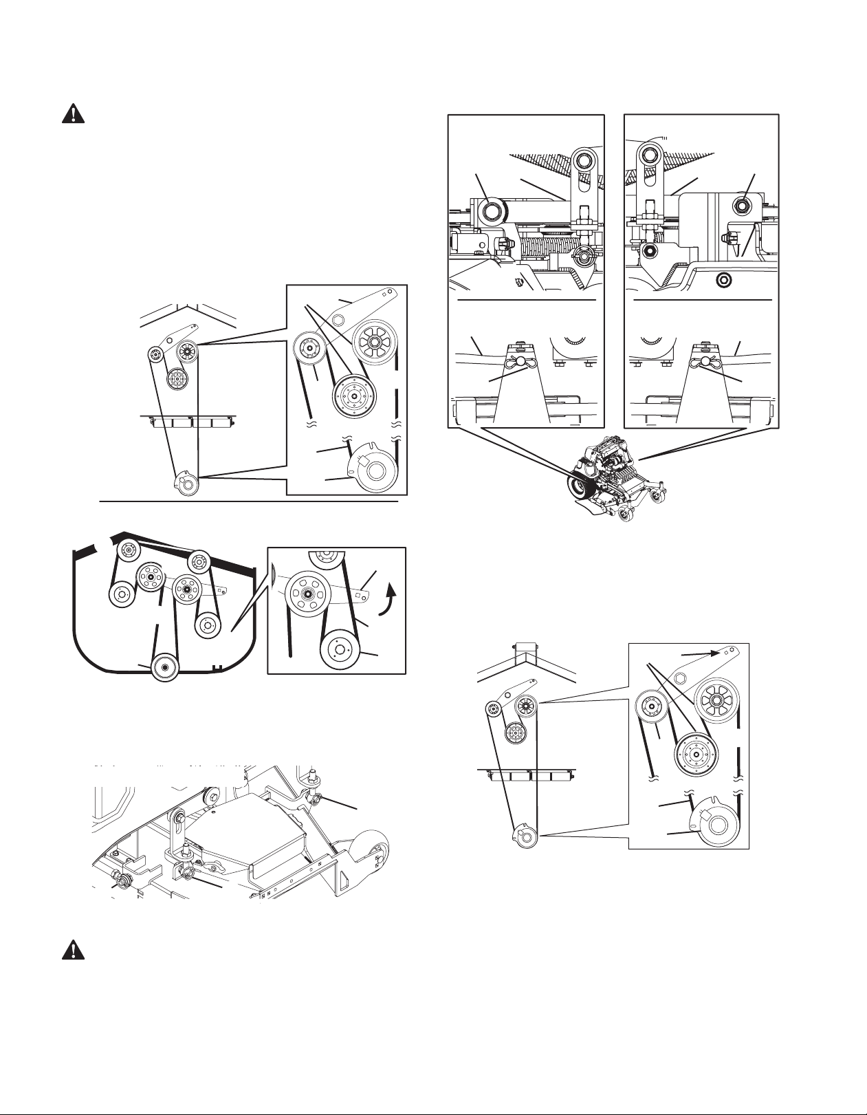
3. Using a 1⁄2” (12.7 mm) drive in the idler pulley bracket (a), turn the wrench towards
the front of the mower and slide the PTO belt (b) off the deck pulleys (c) and the PTO
clutch (d). See Figure 32.
48 and 54 Inch Decks
(b)
(c)
(c)
(a)
(d)
(b)
(d)
(a)
(b)
(c)
(c)
(c)
(c)
(c)
36 Inch Decks
(b)
(c)
(a)
Figure 32
4. Remove the four lynch pins (e) that secure the deck to the deck lift assembly. See
Figure 33.
5. Remove the lynch pin (f) securing the rear stabilizer bar to the rear, right side of the
deck. See Figure 33.
(f)
(e)
(e)
NOTE: Right side of mower deck shown
Figure 33
WARNING: The spring is under tension due to the weight of the deck. When
removing the lift linkage from the deck the tension of the springs will go
from the deck to the deck lift handle. Not capturing the deck height index
by placing the clevis pin behind the lowest position while removing the lift
linkage from the deck will cause it to snap back.
6. Remove the hex screws (g) flange lock nuts (h) securing the front deck control rods (i)
to the deck. See Figure 34.
(f)
(f)
(c, d)
(c, d)
(f)
(e)
(f)
(e)
48 and 54 Inch Decks 48 and 54 Inch Decks
36 Inch Decks 36 Inch Decks
Figure 34
7. Turn front wheels as if to make a pivot turn.
8. Shift the deck toward the right side of the mower and remove.
9. Reverse STEPS 1 - 8 to install the PTO belt and deck.
Replacing the PTO Belt - 48 and 54 Inch Decks Only
1. Remove the PTO belt (a) from the deck as instructed in STEPS 1 - 3 in Removing/
Installing The Deck on page 22.
(a)
(e)
(b)
(c)
(a)
(d)
Figure 35
2. Route the new PTO belt (a) around the PTO clutch (b) and PTO pulleys (c) as shown
in Figure 35.
3. After routing the belt around the PTO pulleys, use a 1⁄2” (12.7 mm) drive in the idler
pulley bracket (d) and turn towards the right of the mower to finish routing the belt
around the idler pulley (e).
PRODUCT CARE, cont'd
Loading ...
Loading ...
Loading ...