iCRRFTSMRNq
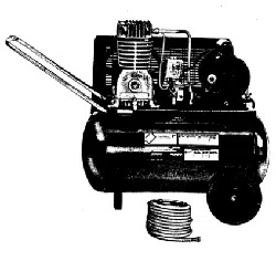
Oil Lubricated
Two Stage
Stationary
AIR COMPRESSOR
Model No.
919.167802
• Safety Guidelines
• Assembly
• Operation
• Maintenance
• Service and Adjustments
• Troubleshooting
• Repair Parts
CAUTION: Read the Safety Guidelines and
All Instructions Carefully Before Operating.
Sears, Roebuck and Co., Hoffman Estates, IL 60179 U.S.A.
Visit our Craftsman website: www.sears.com/craftsman
D30092 Rev0 9/26/03
WARRANTY ................................................ 2
SPECIFICATION CHART ..................................... 3
SAFETY GUIDELINES ...................................... 3-8
GLOSSARY ................................................ 9
ACCESSORIES ............................................. 9
DUTY CYCLE .............................................. 9
ASSEMBLY ............................................... 10
INSTALLATION .......................................... 11-13
OPERATION ............................................ 14-16
MAINTENANCE ......................................... 17-20
SERVICE AND ADJUSTMENTS ............................ 21-22
STORAGE ................................................ 22
TROUBLESHOOTING GUIDE .............................. 23-26
REPAIR PARTS ......................................... 27-31
ESPAI_IOL .............................................. 32-56
NOTES/NOTAS ......................................... 57-58
REPAIR PROTECTION AGREEMENTS ......................... 59
HOW TO ORDER REPAIR PARTS ...................... back cover
ltl__1;| ;[_I_ hi"
FULL ONE YEAR WARRANTY AIR COMPRESSOR
If this CRAFTSMAN Air Compressor fails due to a defect in material or
workmanship within one year from the date of purchase, Sears will at its
option repair or replace it free of charge. Contact your nearest Sears Service
Center (1-800-4-MY-HOME ®)to arrange for repair, or return the Air
Compressor to the place of purchase for replacement.
If this Air Compressor is used for commercial or rental purposes, this warrant
applies for only ninety days from the date of purchase.
This warranty gives you specific legal rights and you may have other rights
which vary from state to state.
Sears, Roebuck and Co., Dept. 817WA, Hoffman Estates, IL 60179
D30092 2=ENG
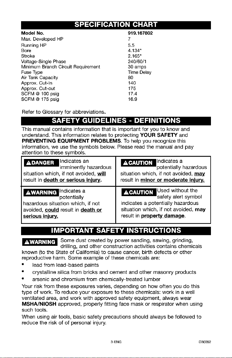
Model No. 919,167802
Max. Developed HP 7
Running HP 5.5
Sore 4.134"
Stroke 2.165"
Voltage-Single Phase 240/60/1
Minimum Branch Circuit Requirement 30 amps
Fuse Type Time Delay
Air Tank Capacity 80
Approx. Cut-In 140
Approx. Cut-out 175
SCFM @ 100 psig 17.4
SCFM @ 175 psig 16.9
Refer to Glossary for abbreviations.
This manual contains information that is important for you to know and
understand. This information relates to protecting YOUR SAFETY and
PREVENTING EQUIPMENT PROBLEMS. To help you recognize this
information, we use the symbols below. Please read the manual and pay
attention to these symbols.
I_'_J_ Indicates an
imminently hazardous
situation which, if not avoided, will
result in death or serious injury.
I_'_J_'_'_ Indicates a
potentially
hazardous situation which, if not
avoided, could result in death or
serious injury.
_'_1'_J_ Indicates a
potentially hazardous
situation which, if not avoided,
result in minor or moderate injury.
_T_'_Used without the
safety alert symbol
indicates a potentially hazardous
situation which, if not avoided, may
result in property damaae.
Ih_l_o]-'tnq.+1+id_"Y.4_l_,_'d_[IP.[-:-]ljt,ttl_o,]njl[o_]P.[-.+
_Some dust created by power sanding, sawing, grinding,
drilling, and other construction activities contains chemicals
known (to the State of California) to cause cancer, birth defects or other
reproductive harm. Some example of these chemicals are:
• lead from lead-based paints
• crystalline silica from bricks and cement and other masonry products
• arsenic and chromium from chemically-treated lumber
Your risk from these exposures varies, depending on how often you do this
type of work. To reduce your exposure to these chemicals: work in a well
ventilated area, and work with approved safety equipment, always wear
MSHA/NIOSR approved, properly fitting face mask or respirator when using
such tools.
When using air tools, basic safety precautions should always be followed to
reduce the risk of of personal injury.
3-ENG [330092
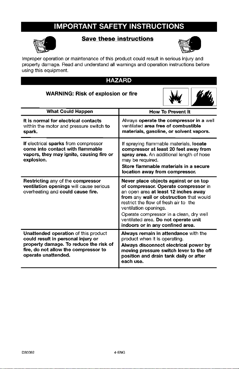
Save these instructions
improper operation or maintenance of this product could result in serious injury and
property damage. Read and understand all warnings and operation instructions before
using this equipment.
:r:_rJ:_;!m
WARNING: Risk of explosion or fire
What Could Happen How To Prevent It
tt is normal for electrical contacts Always operate the compressor in a well
within the motor and pressure switch to ventilated area free of combustible
spark, materials, gasoline, or solvent vapors.
tf electrical sparks from compressor if spraying flammable materials, locate
come into contact with flammable compressor at least 20 feet away from
vapors, they may ignite, causing fire or spray area. An additional length of hose
explosion, may be required.
Store flammable materials in a secure
location away from compressor.
Restricting any of the compressor
ventilation openings will cause serious
overheating and could cause fire.
Unattended operation of this product
could result in personal injury or
property damage. To reduce the risk of
fire, do not allow the compressor to
operate unattended.
Never place objects against or on top
of compressor. Operate compressor in
an open area at least 12 inches away
from any wall or obstruction that would
restrict the flow of fresh air to the
ventilation openings.
Operate compressor in a clean, dry well
ventilated area. Do not operate unit
indoors or in any confined area.
Always remain in attendance with the
product when it is operating.
Always disconnect electrical power by
moving pressure switch lever to the off
position and drain tank daily or after
each use.
D30092 4=ENG
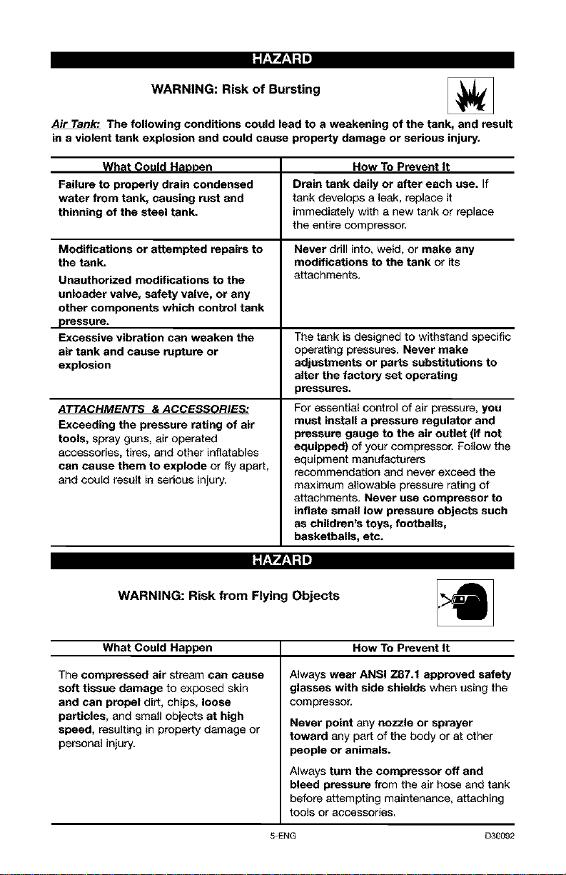
WARNING: Risk of Bursting
Air Tank', The following conditions could lead to a weakening of the tank, and result
in a violent tank explosion and could cause property damage or serious injury.
What Could Haopen How To Prevent It
Failure to properly drain condensed Drain tank daily or after each use. If
water from tank, causing rust and tank develops a leak, replace it
thinning of the steel tank. immediately with a new tank or replace
the entire compressor,
Modifications or attempted repairs to Never drill into, weld, or make any
the tank. modifications to the tank or its
Unauthorized modifications to the attachments.
unloader valve, safety valve, or any
other components which control tank
pressure.
Excessive vibration can weaken the The tank is designed to withstand specific
air tank and cause rupture or operating pressures. Never make
explosion adjustments or parts substitutions to
alter the factory set operating
pressures.
ATTACHMENTS & ACCESSORIES:
Exceeding the pressure rating of air
tools, spray guns, air operated
accessories, tires, and other inflatables
can cause them to explode or fly apart,
and could result in serious injury.
For essential control of air pressure, you
must install a pressure regulator and
pressure gauge to the air outlet (if not
equipped) of your compressor. Follow the
equipment manufacturers
recommendation and never exceed the
maximum allowable pressure rating of
attachments. Never use compressor to
inflate small low pressure objects such
as children's toys, footballs,
basketballs, etc.
-"f.,_'_f.,1"1=
WARNING: Risk from Flying Objects
What Could Happen How ToPrevent It
The compressed air stream can cause
soft tissue damage to exposed skin
and can propel dirt, chips, loose
particles, and small objects at high
speed, resulting in property damage or
personal injury.
Always wear ANSI Z87.f approved safety
glasses with side shields when using the
compressor,
Never point any nozzle or sprayer
toward any part of the body or at other
people or animals.
Always turn the compressor off end
bleed pressure from the air hose and tank
before attempting maintenance, attaching
tOOlS or accessories,
5-ENG D30092
:f:1"4_;ll
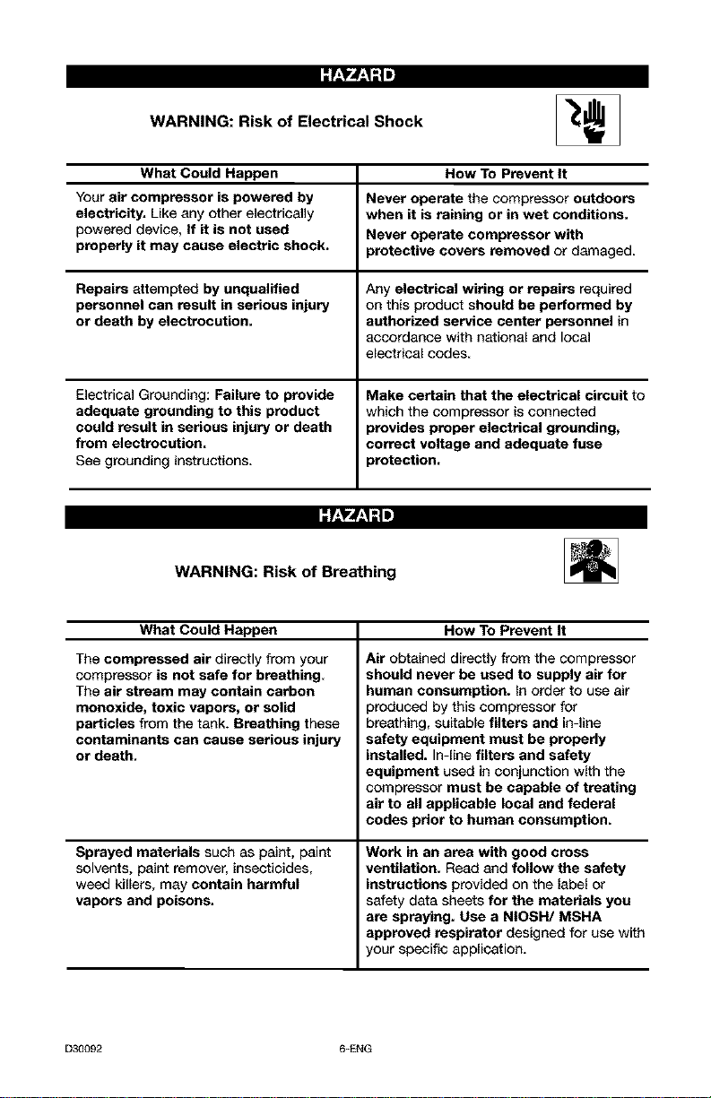
WARNING: Risk of Electrical Shock _J
What Could Happen
Your air compressor is powered by
electricity. Like any other electrically
powered device, If it is not used
properly it may cause electric shock.
Repairs attempted by unqualified
personnel can result in serious injury
or death by electrocution.
Electrical Grounding: Failure to provide
adequate grounding to this product
could result in serious injury or death
from electrocution.
See grounding instructions,
How To Prevent It
Never operate the compressor outdoors
when it is raining or in wet conditions.
Never operate compressor with
protective covers removed or damaged.
Any electrical wiring or repairs required
on this product should be performed by
authorized service center personnel in
accordance with national and local
electrical codes,
Make certain that the electrical circuit to
which the compressor is connected
provides proper electrical grounding,
correct voltage and adequate fuse
protection.
WARNING: Risk of Breathing
What Could Happen How To Prevent It
The compressed air directly from your
compressor is not safe for breathing.
The air stream may contain carbon
monoxide, toxic vapors, or solid
particles from the tank. Breathing these
contaminants can cause serious injury
or death.
Sprayed materials such as paint, paint
solvents, paint remover, insecticides,
weed killers, may contain harmful
vapors and poisons,
Air obtained directly from the compressor
should never be used to supply air for
human consumption, in order to use air
produced by this compressor for
breathing, suitable filters and in-line
safety equipment must be properly
installed. In-line filters and safety
equipment used in conjunction with the
compressor must be capable of treating
air to all applicable local and federal
codes prior to human consumption.
Work in an area with good cross
ventilation. Read and follow the safety
instructions provided on the label or
safety data sheets for the materials you
are spraying. Use a NtOSH/MSHA
approved respirator designed for use with
your specific application.
D30092 6=ENG
f-'_J-'1_ i
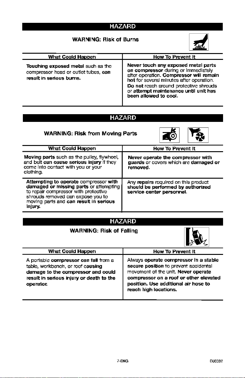
WARNING: Risk of Burns
What Gould Happen
Touching exposed metal such _ the
oompre_r hcsd or outlet tubes, _an
result in serious bums.
How To Prevent It
Never touch any exposed metal parts
on compressor during or immedistely
sft_r operation. Gompressor will remain
hot for scvcml minutes a_er operation,
Do net r_sch sreund protective shrouds
or attempt mairrtenance unbl unit has
been allowed to cool,
;F-'YJ-'I:,]J
WARNING: Risk from Moving Parts _T)
What Could Happen How To Prevent It
Moving parts such a_ the pulley, flywheel, Never operate the compressor with
and belt can cause serious injury if they guards or covers which a_ damaged or
come into _,ontact with you or your removed,
el_hing.
Attempting to operate compressor with Any repairs r_quired on this product
damaged or missing parts or _cm_ing should be performed by authorized
to r_pair compressor with profeutivc service center personnel,
shrouds removed c_n expose you to
moving parts and can result in serious
injury.
;F_,yJ_,_!:,]J
WARNING: Risk of Falling
What Gould Happen
A portable compressor can fall _m a
table, workbench, or roof causing
damage to the compressor and could
result in serious injury or death to the
operator.
How To Prevent It
Always operate compressor in a stable
secure posibon to prevent accidental
movement of the unit. Never operate
compressor On a roof or ether elevated
position. Use additional air hose to
reach high locations.
7-ENG L33_92
;7-'_rJ-q:t J
;7-'_r.L'_!:t J
WARNING: Risk of Unsafe Operation
What Could Rappen How To Prevent It
Unsafe operation of your air compressor
could lead to serious injury or death to
you or others.
Renew and understand all instructions
and warnings in this manual,
Become familiar with the operation and
controls of the air _mprsssor,
Keep operating area clear of all persons,
pets, and obstacles,
Keep children away _m the air
compressor at all itrnes,
Do not operate the product when
fatigued or under the influence of
alcohol or drugs. Stay alert at all times.
Never defeat the safely faatures of this
preduct.
Equip area of operation with a fire
extinguisher.
DO not operate machine with missing,
broken, or unauthorized parts.
SAVE THESE INSTRUCTIONS
:I_2 _ENG
Become familiar with these terms
before operating the unit.
CFM Cubicfest per minute.
SCFM: Standard cubic feet per
minute; a unit of measure of air
delivery.
PSIG: Pounds per square inch
gauge; a unit of measure of pressure.
Code Certification: Products that
bear one or more of the following
marks: UL, CUL, ETL, CETL, have
been evaluated by OSHA certified
independent safety laboratories and
meet the applicable Underwriters
Laboratories Standards for Safety,
Cut*In Pressure: While the motor is
off, air tank pressure drops as you
continue to use your accessory.
When the tank pressure drops to a
certain low level the motor will restart
automatically. Tr_e low pressure at
which the motor automatically
restarts is called "cut-in" pressure,
Cut-Out Pressure: When an air
compressor is turned on and begins
to run, air pressure in the air tank
begins to build, It builds to a certain
high pressure before the motor
automatically shuts off - protecting
your air tank from pressure higher
than its capacity. The high pressure
at which the motor shuts Off is called
"cut -out" preesure.
Branch Circuit: Circuit carrying
electricity from electrical panel to
outlet,
To Lock Out Power: Place a lock on
the line power switch SOno one else
can turn on the powe_
Troisunit is capable of powering the following Accessories. The accessories are
available through the current Power and Hand Tool Catalog or full-line Sears
stores.
Accessories
• In Line Filter
• Tire Air Chuck
• Quick Connector Sets (various
sizes)
• Air Pressure Regulators
• Oil Fog Lubricators
• Air Hose: 1/4", 5/16", or 3/8" OR
1/2" inside diameter in various
lengths
Troisair compressor pump is capable
of running continuously. However, to
prolong the life of your air
compressor, it is recommended that a
50%-75% average duty cycle be
maintained; that is, the air
compressor pump should not run
more than 30-45 minutes in any given
hour.
_-ENG L3_92
Contents of Carton
1 - Air Compressor
1 - Parts bag containing:
1 - Operator's Manual
1 - Parts Manual
4 - 5/8" Washers
Tools Required for Assembly
1 - g/16" socket or open end wrench
1 - electric drill
iI=l,t'
Multi-Viscosity
motor oils, like
10W 80, should not be used in an air
compressor. They leave carbon
deposits on critical components,
thus reducing performance and
compressor life. Use air compressor
oil only..
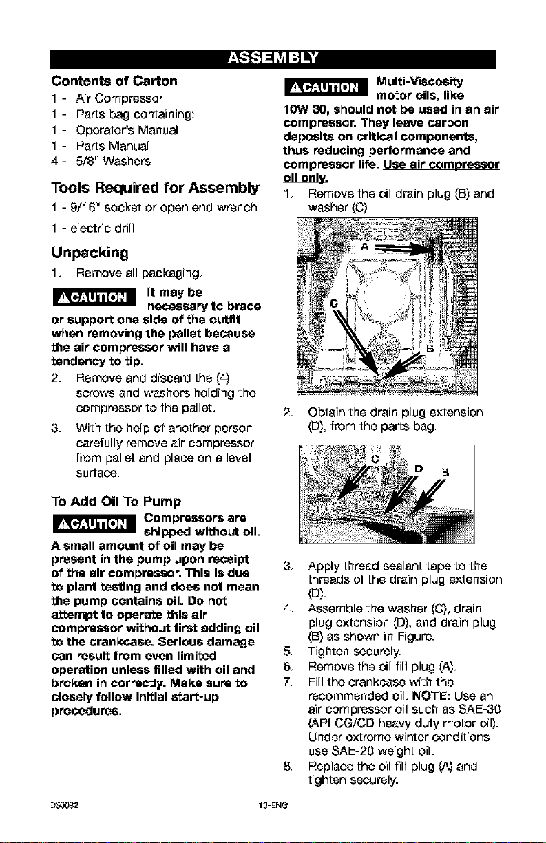
1, Remove the oil drain plug (B) and
washer (C).
Unpacking
1. Remove all packaging,
It may be
necessary to brace
or support one side of the outfit
when removing the pallet because
the air compressor will have a
tendency to tip.
2. Remove and discard the (4)
screws and washers holding the
compressor to the pallet.
3. With the help of another person
carefully remove air compressor
from pallet and place on a level
surface,
To Add Oil To Pump
_ Compressore are
shipped without oil.
A small amount of oil may be
present in the pump upon receipt
of the air compressor. This is due
to plant testing and does not mean
the pump contains oil. Do not
attempt to operate this air
compressor without first adding oil
to the crankcase. Serious damage
can result from even limited
operation unless filled with oil and
broken in correctly. Make sure to
closely follow initial start*up
procedures.
2, Obtain the drain plug extension
([3), from the parts bag,
3, Apply thread sealant tape to the
threads of the drain plug extension
4, Assemble the washer (C), drain
plug extension (D), and drain plug
(B) as shown in Figure.
5, Tighten securely.
6, Remove the oil fill plug (A),
7, Fill the crankcase with the
recommended oil. NOTE: Use an
air compressor oil such as SAE-30
(API CG/CD heavy duty motor oil).
Under extreme winter conditions
use SAE-20 weight oil.
8, Replace the oil fill plug (A) and
tighten securely.
--)_2 1,q-ENG
HOW TO SET UP YOUR UNIT
Location of the Air Compressor
• Locate the air compressor in a
clean, dry, and well ventilated
area,
• Locate the air compressor at
least 12" away from the wall or
other obetruc'tions that will
interfere with the flow of air.
• Locate the air compressor as
close to the main power supply
as possible to avoid using long
lengths of electrical wiring.
NOTE: Long lengths of electrical
wiring could cause power loss to
the motor.
• Tr_eair filter must be kept clear
of obetruc'tions which could
reduce air flow to the air
compressor.
Anchoring of the Air
Compressor
Excessive Vibration
can weaken the air
tank and cause an explosion. The
compressor must be properly
mounted.
Tr_eair compressor MUST be bolted
to a solid, level surface.
Hardware needed:
4 - Concrete anchors (not supplied)
4 - 3/8" Lag screw to fit concrete
anchors (not supplied)
4 - 5/8" Washer shims (found in
parts bag, if needed)
1, Place the air compressor on on a
solid, level surface,
2, Mark the surfaes using the holes
in the air compressor feet as a
template,
3, Drill holes in the surface for the
concrete anchors. Install
concrete anchors.
4, Une-up holes in surface with
holes in air compressor feet.
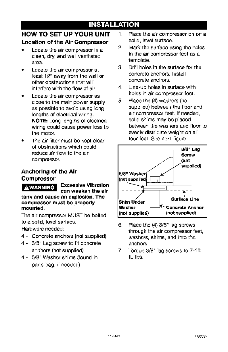
5, Place the (4) washers (not
supplied) between the floor and
air compressor feet, If needed,
solid shims may be placed
between the washers and floor to
evenly distribute weight on all
four feet, See next figure.
3/8' Lag
_rew
(net
--_--
Surface Line
ShimUnder
Washer Concrete Anchor
[notsupplied) (not supplied)
6, Place the (4) 3/8" lag screws
through the air compressor feet,
washers, shims, and into the
anchors,
7, Torque 3/8" lag screws to 7-10
fL-Ibs,
11-ENG L33CC9_2
Wiring Instructions
_Risk of elec_ical
shock. Improper
electrical grounding can result in
electrical shock. The wiring should
be done by a qualified electrician
to comply with national and local
electrical codes.
A qualified electrician needs to knows
the following before wiring:
1. Tr_eamperage rating of the
electrical box should be
adequate, Refer to the product
specifications, found in the front
of this manual, for this
information.
2. Tr_esupply line should have the
same electrical charac'tedsfice
(voltage, cycle, phase) as the
motor. Refer to the motor
nameplate, on side of motor, for
this information,
NOTE: Tr_ewiring must be the same
as the motor nameplate voltage plus
or minus 10%. Refer to local codes
for recommended wire sizes, correct
wire size, and maximum wire run;
undersize wire causes high amp draw
and overheafing to the moto_
Risk of electrical
shock. Electrical
wiring must be located away _om
hot surfaces such as manifold
assembly, compressor outlet tubes,
heads, or cylinders.
GROUNDING INSTRUCTIONS
Trois product should be connected to
a metallic, permanent wiring system,
or an equipment-grounding terminal
or lead on the product and comply
with national and local electrical
codes.
Refer to the product specification
found in the front of this manual for
the voltage and minimum branch
circuit requirements,
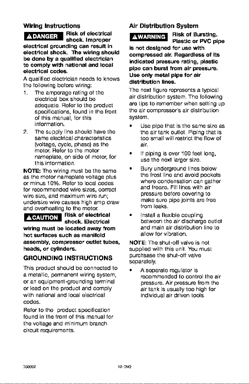
Air Distribution System
Risk of Bursting.
Plastic or PVC pipe
is not designed for use with
compressed air. Regardless of its
indicated pressure rating, plastic
pipe can burst _om air pressure.
Use only metal pipe for air
distribution lines.
The next figure represents a typical
air distribution system, The following
are tips to remember when setting up
the air eompressor's air distribution
system.
Use pipe that is the same size as
the air tank outlet, l=iping that is
too small will restrict the flow of
air.
• If piping is over 100 feet long,
use the next larger size,
Bury underground lines below
the frost line and avoid pockets
where condensation can gather
and freeze. Fill lines with air
pressure before covering to
make sure pipe joints are free
from leaks.
Install a flexible coupling
between the air discharge outlet
and main air distribution line to
allow for vibration.
NOTE: The shut-off valve is not
supplied with this unit, You must
purehsase the shut-off valve
separately.
A separate regulator is
recommended to control the air
pressure. Air pressure from the
air tank is usually too high for
individual air driven tools,
--I_2 12-ENG
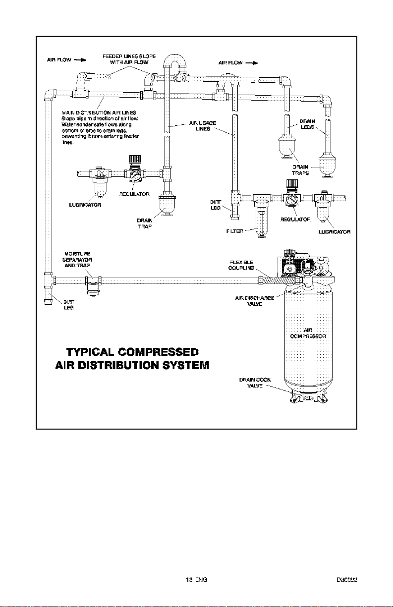
LEG
TYPICAL COMPRESSED
AIR DISTRIBUTION SYSTEM
AIR
CCM PRE,_OR
I_Al_J _CK _
VALVE _
13-ENG L33_92
Know Your Air Compressor
READ THIS OWNER'S MANUAL AND SAFETY RULES BEFORE OPERATING
YOUR UNI_ Compare the illustrations with your unit to familiarize yourself with
the location of various controls and adjustments. Save this manual for future
reference,
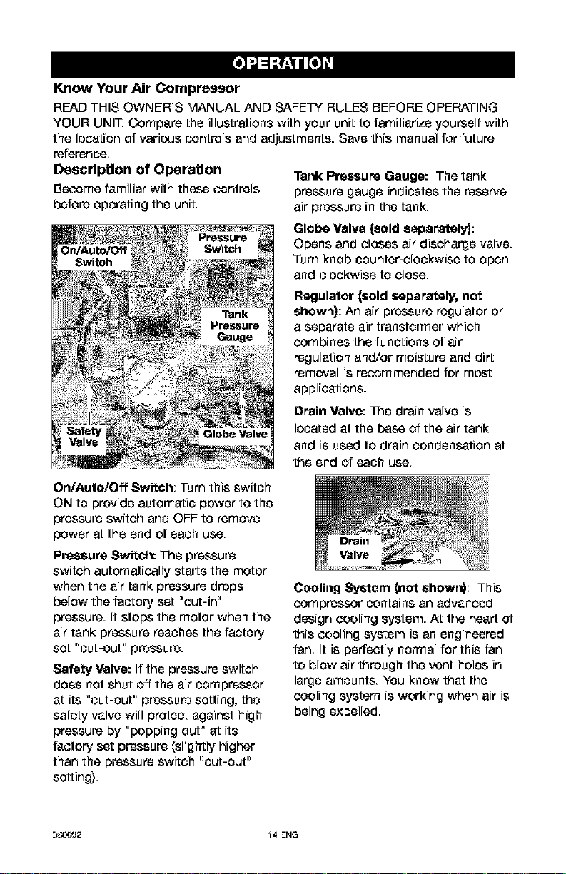
Description Of Operation
Become familiar with these controls
before operating the unit.
Tank Pressure Gauge: The tank
pressure gauge indicates the reserve
air pressure in the tank,
Glebe Valve (sold separately):
Opens and closes air discharge valve.
Turn knob counter-clockwise to open
and clockwise to close,
Regulator (sold separe_ely, not
shown):/_ air pressure regulator or
a separate air transformer which
combines the functions of air
regulation and/or moisture and dirt
removal is recommended for most
applications.
Drain Valve: Tr_e drain valve is
located at the base of the air tank
and is used to drain condensation at
the end of each use,
On/Auto/Off Switch; Turn this switch
ON to provide automatic power to the
pressure switch and OFF to remove
power at the end of each use,
Pressure Switch: The pressure
switch automatically starts the motor
when the air tank pressure drops
below the factory set "cut-in"
pressure, It stops the motor when the
air tank pressure reaches the factory
set "cut-out" pressure.
Safety Valve: If the pressure switch
does not shut off the air compressor
at its "cut-out" pressure setting, the
safety valve will protect against high
pressure by "popping out" at its
factory set pressure (slightly higher
than the pressure switch "cut-out"
setting).
Cooling System (not shown); This
compressor contains an advanced
design cooling system. At the head 04
this cooling system is an engineered
fan, It is perfectly normal for this fan
to blow air through the vent holes in
large amounts. You know that the
cooling system is working when air is
being expelled,
--)_,YJ£2 14-ENG
Air Compressor Pump (not shown):
Compresses air into the air tank.
Working air is not available until the
compressor has raised the air tank
pressure above that required at the
air outlet.
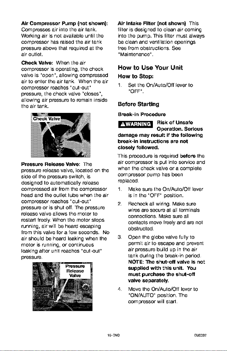
Check Valve: When the air
compressor is operating, the check
valve is "open", allowing compressed
air to enter the air tank, When the air
compressor reaches "cut-out"
pressure, the check valve "closes",
allowing air pressure to remain inside
the air tank.
Pressure Release Valve: The
pressure release valve, located on the
side of the pressure switch, is
designed to automatically release
compressed air from the compressor
head and the outlet tube when the air
compressor reaches "out-out"
pressure or is shut off, Tr_epressure
release valve allows the motor to
restart freely. When the motor stops
running, air will be heard escaping
from this valve for a few seconds, No
air should be heard leaking when the
motor is running, or continuous
leaking after unit reaches "out-out"
pressure,
Air Intake Filter (not shown) This
filter is designed to clean air coming
into the pump. Troisfilter must always
be clean and ventilation openings
free from obstructions, See
"Maintenance'.
How to Use Your Unit
How to Stop:
1, Set the 0n/Auto/0ff lever to
_,OFF_,.
Before Starting
Break*in Procedure
Risk of Unsafe
Operation. Serious
damage may result if the following
break*in instructions are not
closely followed.
This procedure is required before the
air compressor is put into service and
when the check valve or a complete
compressor pump has been
replaced,
1, Make sure the On/Auto/Off lever
is in the "OFF" position.
2, Recheck all wiring, Make sure
wires are secure at all terminals
connections, Make sure all
contacts move freely and are not
obstructed,
3, Open the globe valve fully to
permit air to escape and prevent
air pressure build up in the air
tank during the braak-in period,
NOTE: The shut*off valve is net
supplied with this unit. You
must purchase the shut-off
valve separately.
4, Move the 0n/Auto/Off lever to
"0N/AUT0" position, The
compressor will start,
15-ENG D_CC9_2
5. Run the cornpressor for 20
minutes, Make sure the globe
valve is open and there is
minimal air pressure build-up in
tank,
6. Check all air line fittings and
connections/piping for air leaks
by applying a soap solution,
Correct if necessary. NOTE:
Minor leaks can cause the air
compressor to overwork,
resulting in premature breakdown
or inadequate performance.
7. Check for excessive vibration.
Readjust or shim air compressor
feet, if necessary.
8. After 20 minutes, close the globe
valve, The air receiver will fill to
"cut-out" pressure and the motor
will stop.
Before Each Start-Up:
1. Place On/Auto/Off lever to
._OFF,_"
2. Close the globe valve.
3. Attach hose and accessories.
NOTE: A regulator MUST be
installed when using accessories
reted at less than 175 PSI,
Risk of Bursting.
Too much air
pressure causes a hazardous risk
of bursting. Cheek the
manufacturer's maximum pressure
rating for air tools and accessories.
The regulator outlet pressure must
never exceed the maximum
pressure rating.
How to Start
1, Turn the On/Auto/Off lever to
"AUTO" and allow tank pressure
to build, Motor will stop when
tank pressure reaches "cut-out"
pressure.
2, When the tank pressure reaches
"cut-out" pressure open the
globe valve,
IMPORTANT: When using regulator
and other accessories refer to the
manufacturer's instructions,
_-)_,.v3£2 I_ENG
kVAr='llI_/ II=1_V=al_[_
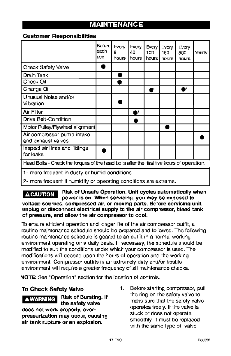
Customer Responsibilities
5_ore Every Every Every Every Every,
_eh 8 _-0 100 180 500 Yearly
JSe hOUP3 hours houP3 hours houi_
Check Safety Valve •
Drain Tank •
Check Oil •
Change Oil •_ •_
Unusual Noise and/or
Vibration •
Air Filter •_
Drive Belt-Condition •
Motor l=ulley/Flywheel alignrnen •
Air compressor pump intake •
and exhaust valves
Inspect air lines and fittings •
for leaks
HeadBolts - Check the torques of tie headbolts after tie first fivehours of operation,
1- more frequent in dusty or humid conditions
2- more frequent if humidity or operating conditions are extreme.
Risk of Unsafe Operation. Unit cycles automatically when
power is on. When sarvioing, you may be exposed to
voltage sources, compressed air, or moving parts. Before servicing unit
unplug or disconnect electrical supply to the air compressor, bleed tank
of pressure, and allow the air compressor to cool.
To ensure efficient operation and longer life of the air compressor outfit, a
routine maintenance schedule should be prepared and followed, The following
routine maintenance schedule is geared to an outfit in a normal working
environment operating on a daily basis. If necessary, the schedule should be
modified to suit the conditions under which your compressor is used. The
modifications will depend upon the hours of operation and the working
environment, Compressor outfits in an extremely dirty and/or hostile
environment will require a greater frequency of all maintenance checks.
NOTE: See "Operation" section for the location of controls,
To Check Safety Valve
Risk of Bursting. If
the safety valve
does not work properly, over-
pressurization may occur, causing
air tank rupture or an explosion.
1.
Before starting compressor, pull
the ring on the safety valve to
make sure that the safety valve
operates freely. Ifthe valve is
stuck or does not operate
smoothly, it must be replaced
with the same type of valve,
17-ENG D_CC9_2
To Drain Tank
NOTE: Operation of the air
compressor will cause condensation
to build up in the air tank. Always
drain tank on a washable surface or
in a suitable container to prevent
damaging or staining surfaces.
1. Set the On/Auto/Off lever to
_,OFF,_.
2. Close the globe valve.
3. Remove the air tool or
accessory.
4. Open the globe valve and allow
the air to slowly bleed from the
air tank until tank pressure is
approximately 20 psi.
5. Close the globe valve.
6. Drain water from air tank by
opening drain valve (counter-
clockwise) on bottom of tank.
I_ Risk of Bursting.
Water will
condense in the air tank. If not
drained, water will corrode and
weaken the air tank causing a risk
of air tank rapture.
7. After the water has been
drained, close the drain valve
(clockwise). The air compressor
can now be stored.
NOTE: If drain valve is plugged,
release all air pressure. The valve
can then be removed, cleaned, then
reinstalled.
Oil
NOTE: Use a air compressor oil such
as SAE-30 (API CG/CD heavy duty
motor oil). Under extreme winter
conditions use SAE-20 weight oil.
NOTE: Crankcase oil capacity is
approximately 60 fluid ounces (1.8 l).
Checking
1. The oil level should be to the
middle of the sight glass (C).
2. If needed remove oil fill plug (A)
and slowly add oil until it reaches
the middle of the sight glass.
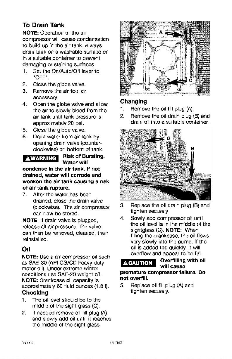
Changing
1. Remove the oil fill plug (A).
2. Remove the oil drain plug (B) and
drain oil into a suitable oontaine_
3. Replace the oil drain plug (B) and
tighten securely
4. Sowly add compressor oil until
the oil level is in the middle of the
sightglass (C). NOTE: When
filling the crankcase, the oil flows
very slowly into the pump. If the
oil is added too quickly, it will
overflow and appear to be full.
I_ Overfilling with oil
will cause
premature compressor failure. Do
not overfill.
5, Replace oil fill plug (A) and
tighten securely.
_-)_,.vJ£2 15-ENG
Air Filter - Inspection and
Replacement
I_qqPrf_l Risk of Burns.
Compressor head
and cylinder sleeve are very hot.
Do net touch. Allow compressor to
cool prior to servicing.
A dirty air filter will not allow the
compressor to operate at full
capacity. Keep the air filter clean at
all times,
1. Remove the air filter cover.
2. Remove the air filter from filter
coven
IMPORTANT: Do not operate the
compressor with the air filter
removed,
3. Place new air filter into filter
coven Refer to the "Repair Parts"
for the correct pad number.
4. Replace air filter cover and lock
into place.
Belt - Replacement
(Refer to the Repair Parts for
replacement belt part number.)
Risk of Moving
Parts. Serious
injury or damage may occur if
parts of the body or loose items
get caught in moving parts. Never
operate the outfit with the belt
guard removed. The belt guard
should be removed only when the
AIR compressor power is
disconnected.
1. Turn air eompP-_,ssoroff, lock out
the power supply, and relieve all
air pressure from the air tank,
2. Removethe belt guard,
3. Mark pump position on saddle.
4. Loosen the motor mounting
screws and slide the motor
toward the air compresso_
5, Remove the belt and replace
with a new one.
6, See the "Adjust Belt Tension"
before tightening motor
mounting screws.
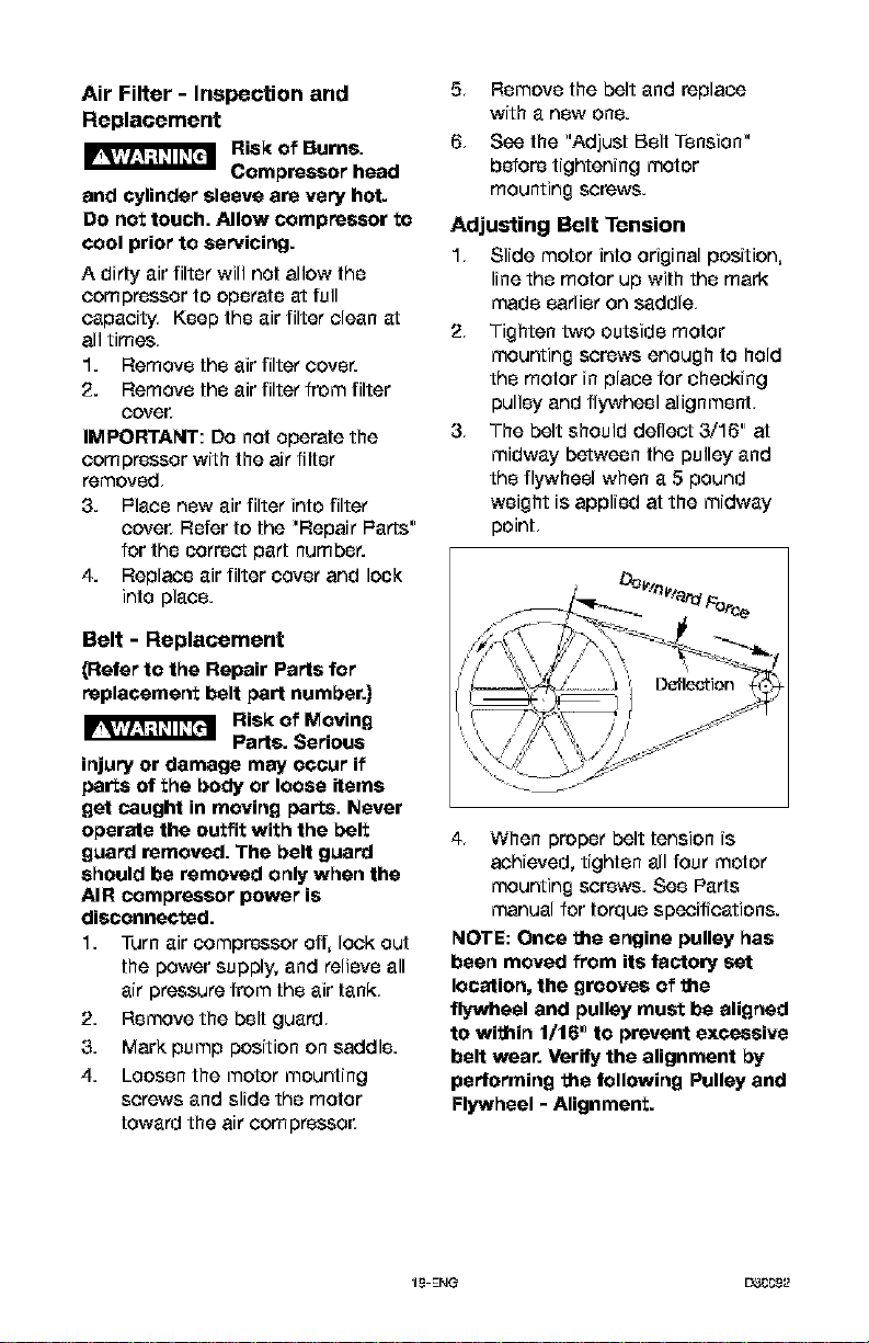
Adjusting Belt Tension
1, Slide motor into original position,
line the motor up with the mark
made earlier on saddle,
2, Tighten two outside motor
mounting screws enough to hold
the motor in place for checking
pulley and flywheel alignment,
3, The belt should delleet 3/16" at
midway between the pulley and
the flywheel when a 5 pound
weight is applied at the midway
point,
Fo,_e
4, When proper belt tension is
achieved, tighten all four motor
mounting screws. See Parts
manual for torque specifications.
NOTE: Once the engine pulley has
been moved from its factory set
location, the grooves of the
flywheel and pulley must be aligned
to within 1/16 _]to prevent excessive
belt wear. Verify the alignment by
performing the following Pulley and
Flywheel - Alignment.
19-ENG EY3CC9_2
Motor Pulley/Flywheel
Alignment
NOTE: Once the motor pulley has
been moved from its factory set
location, the grooves of the flywheel
and pulley must be aligned to within
1/16" to prevent excessive belt wear.
The air compressor flywheel and
motor pulley must be in-line (in the
same plane) within 1/16" to assure
belt retention within flywheel belt
grooves, To check alignment,
perform the following steps:
1. Turn air compressor off, lock out
the power supply, and relieve all
air pressure from the air tank,
2. Remove belt guard
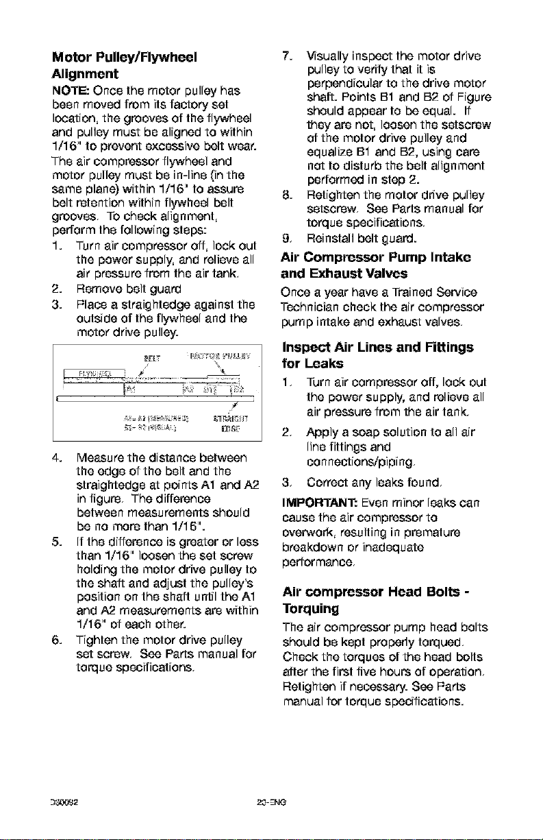
3. Place a straightedge against the
outside of the flywheel and the
motor drive pulley.
4. Measure the distance between
the edge of the belt and the
straightedge at points A1 and A2
in figure, The difference
between measurements should
be no more than 1/16".
5. If the difference is greater or less
than 1/16" loosen the set screw
holding the motor drive pulley to
the shait and adjust the pulley's
position on the shaft until the A1
and A2 measurements are within
1/16" of each other.
6. Tighten the motor drive pulley
set screw, See Parts manual for
torque specifications,
7. Visually inspect the motor drive
pulley to verify that it is
perpendicular to the drive motor
shaft. Points B1 and B2 of Figure
should appear to be equal. If
they are not, loosen the setscrew
04 the motor drive pulley and
equalize B1 and B2, using care
not to disturb the belt alignment
performed in step 2.
8. Retighten the motor drive pulley
setscrew, See Parts manual for
torque specifications,
9, Reinstall belt guard.
Air Compressor Pump Intake
and Exhaust Valves
Once a year have a Trained Service
Technician check the air compressor
pump intake and exhaust valves,
Inspect Air Lines and Fittings
for Leaks
1, Turn air Compressor off, lock out
the power supply, and relieve all
air pressure from the air tank,
2, Apply a soap solution to all air
line fittings and
con neations/piping,
3, Correct any leaks found,
IMPORTAIYT: Even minor leaks can
cause the air compressor to
overwork, resulting in premature
breakdown or inadequate
performance,
Air compressor Head Bolts -
Torquing
The air compressor pump head bolts
should be kept propedy torqued,
Check the torques of the head bolts
after the first five hours of operation,
Retighten if necessary. See Parts
manual for torque specifications.
--)_2 2,0-ENG
ALL MAINTENANCE AND REPAIR
OPERATIONS NOT LISTED MUST BE
PERFORMED BY TRAINED SERVICE
TECHNICIAN,
F_'_I_'_'_,_'_ Risk of Unsafe
Operation. Unit
cycles automatically when power is
on. When servicing, you may be
exposed to voltage sources,
compressed air, or moving parts.
Before servicing unit unplug or
disconnect elec_ical supply to the
air compressor, bleed tank of
pressure, and allow the air
compressor to cool.
To Replace or Clean Check
Valve
1. Release all air pressure from air
tank, See "To Drain Tank" in the
Maintenance section.
2. Turn air compressor off, lock out
the power supply, and relieve all
air pressure from the air tank,
3. Using an adjustable wrench
loosen outlet tube nut at air tank
and pump. Carefully move outlet
tube away from check valve,
4. Using an adjustable wrench
loosen pressure relief tube nut at
air tank and pressure switch.
Carefully move pressure relief
tube away from check valve,
5,
6,
Unscrew the check valve (turn
counterclockwise) using a 7/8"
open end wrench. Note the
orientation for reassembly.
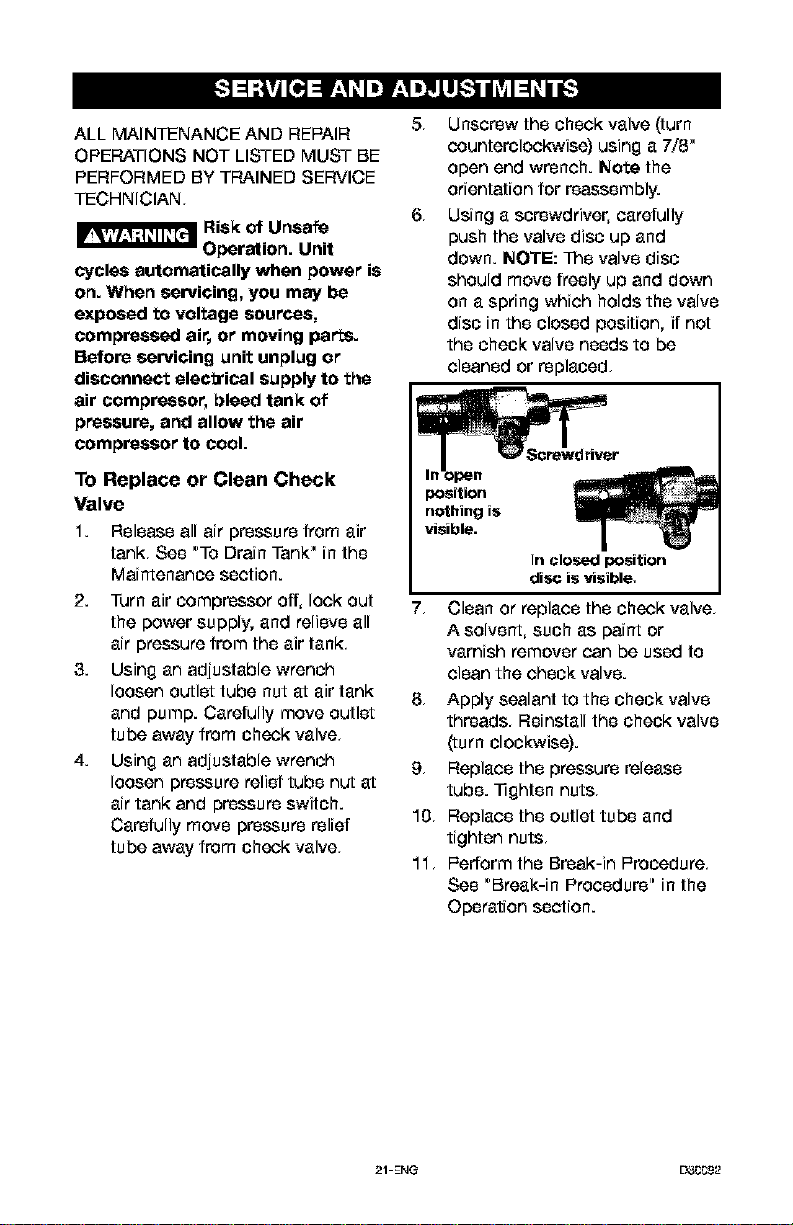
Using a screwdriver, carefully
push the valve disc up and
down. NOTE: Tr_evalve disc
should move freely up and down
on a spring which holds the valve
disc in the closed position, if not
the check valve needs to be
cleaned or replaced,
Screwdriver
7, Clean or replace the check valve,
A solvent, such as paint or
varnish remover can be used to
clean the check valve.
8, Apply sealant to the check valve
threads, Reinstall the check valve
(turn clockwise).
9, Replace the pressure release
tube. Tighten nuts,
10, Replace the outlet tube and
tighten nuts,
11, Pedormthe Break-in Procedure,
See "Break-in Procedure" in the
Operation section.
21-ENG EX_92
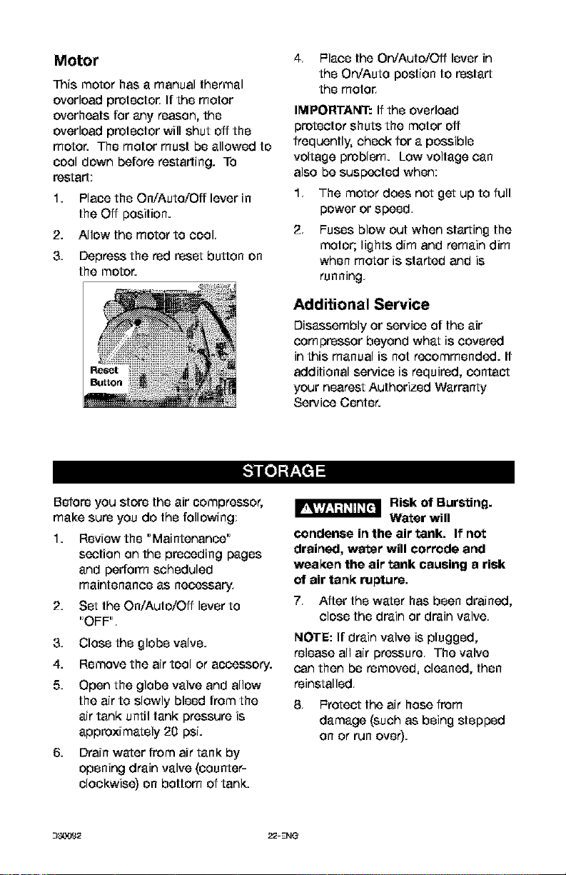
Motor
Trois motor has a manual thermal
overload protecto_ If the motor
overheats for any reason, the
overload protector will shut off the
motor. The motor must be allowed to
cool down before restarting. To
restart;
1. Place the On/Auto/Oft lever in
the Off position.
2. Allow the motor to cool.
3. Depress the red reset button on
the motor.
4. l=laco the On/Auto/Off lever in
the On/Auto postion to restart
the moto_
IMPORTANT: If the overload
protector shuts the motor off
frequently, check for a possible
voltage problem. Low voltage can
also be suspected when;
1. The motor does not get up to full
power or speed.
2. Fuses blow out when starting the
motor; lights dim and remain dim
when meter is started and is
running.
Additional Service
Disassembly or service of the air
compressor beyond what is covered
in this manual is not recommended. If
additional service is required, contact
your nearest Authorized Warranty
Service Center.
Before you store the air compressor,
make sure you do the following;
1. Review the "Maintenance"
section on the preceding pages
and perform scheduled
maintenance as necessary.
2. Set the On/Auto/Off lever to
"OFF".
3. Close the globe valve.
4. Remove the air tool or accessory.
5. Open the globe valve and allow
the air to slowly bleed from the
air tank until tank pressure is
approximately 20 psi.
6. Drain water from air tank by
opening drain valve (counter-
clockwise) on bottom of tank.
I_ Risk of Bursting.
Water will
condense in the air tank. If not
drained, water will corrode and
weaken the air tank causing a risk
of air tank rupture.
7. After the water has been drained,
close the drain or drain valve.
NOTE: If drain valve is plugged,
release all air pressure. The valve
can then be removed, cleaned, then
reinstalled.
8. l=reteet the air hose from
damage (such as being stepped
on or run over).
--)_2 22-EN_
Risk of Unsafe Operation. Unit cycles automatically
when power is on. When servicing, you may be exposed
to voltage sources, compressed air, or moving parts. Before servicing unit
unplug or disconnect electrical supply to the air compressor, bleed tank
of pressure, and allow the air compressor to cool.
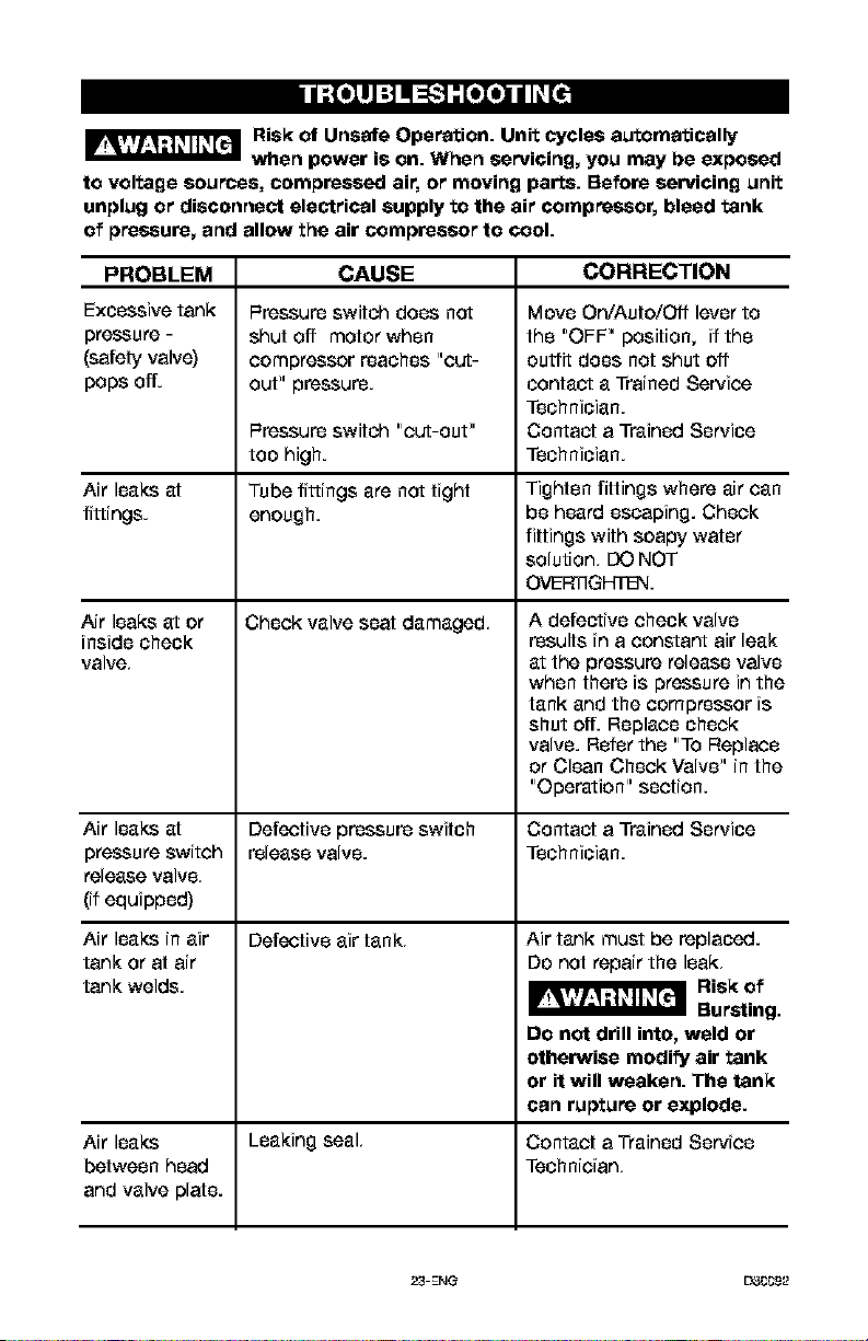
PROBLEM CAUSE CORRECTION
Excessive tank
pr_ure -
(safety valve)
peps off.
Air leaks at
fittings.
Air leaks at or
inside check
valve,
Pressure switch does not
shut off motor when
compressor reaches "out-
OUt_"pressure.
Pressure switch "cut-out"
too high.
Tube fittings are not tight
enough.
Check valve seat damaged,
Move On/Auto/Off lever to
the "OFF" position, if the
outfit does not shut off
contac_ a Trained Service
Technician.
Contact a Trained Service
Technician.
Tighten fittings where air can
be heard escaping. Check
fittings with soapy water
solution, DO NOT
OVER]IGHTE_.
A defective check valve
results in a constant air leak
at the pressure release valve
when there is pressure in the
tank and the compressor is
shut off. Replace check
valve. Refer the "To Replace
or Clean Check Valve" in the
"Operation" section.
Air leaks at Defective pressure switch Contact a Trained Service
pressure switch release valve. Technician.
release valve,
(if equipped)
Air leaks in air Defective air tank,
tank or at air
tank welds.
Air tank must be replaced.
Do not repair the leak,
Risk of
Bursting.
DO not drill into, weld or
otherwise modify air tank
or it will weaken. The tank
can rupture or explode.
Air leaks Leaking seal, Contact a Trained Service
between head Technician,
and valve plate.
23-EN_ EY30092
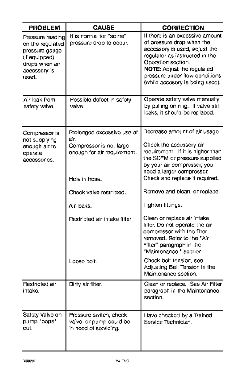
PROBLEM
Pressure readin¢
on the regulated
pressure gauge
(if equipped)
drops when an
accessory is
used.
Air leakfrom
safety valve.
Compressor is
not supplying
enough air to
operate
accessodee.
Restricted air
intake,
Safety Valve on
pump "pops"
out,
CAUSE
It is normal for "some"
pressure drop to occur.
Possible defect in safety
valve.
Prolonged excessive use of
Compressor is not large
enough for air requirement.
Hole in hose.
Check valve restricted.
Air leaks.
Restricted air intake filter
Loose belt.
Dirty air filte_
l=ressure switch, check
valve, or pump could be
in need of servicing.
CORRECTION
if there is an excessive amount
of pressure drop when the
accessory is used, adjust the
regulator as instructed in the
Operation section,
NOTE: Adjust the regulated
pressure under flow conditions
(while accesory is being used).
Operate safety valve manually
by pulling on ring. If valve still
leaks, it should be replaced.
Decrease amount of air usage.
Check the accessory air
requirement, If it is higher than
the SCFM or pressure supplied
by your air compressor, you
need a larger oompresso_
Check and replace if required.
Remove and clean, or replace,
Tighten fittings.
Clean or replace air intake
filter. Do not operate the air
compressor with the filter
removed. Refer to the "Air
Filter" paragraph in the
"Maintenance " section,
Check belt tension, see
Adjusting Belt Tension in the
Maintenance section,
Clean or replace. See Air Filter
paragraph in the Maintenance
section.
Have checked by a Trained
Service Technician,
--)_2 24-ENG
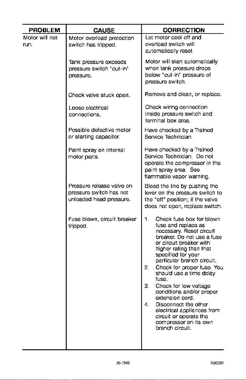
PROBLEM
Motor will not
run,
CAUSE
Motor overload protection
switch has tripped,
Tank pressure exceeds
3ressure switch "cut-in"
3ressure.
]hock valve stuck open.
Loose electrical
connections.
Possible defective motor
or starting capacito_
Paint Spray on internal
motor parts,
Pressure release valve on
pressure switch has not
unloaded head pressure.
Fuse blown, circuit breaker
tripped,
CORRECTION
Let motor cool off and
overload switch will
automatically reset,
Motor will start automatically
when tank pressure drops
below "cut-in" pressure of
pressure switch,
Remove and clean, or replace.
Check wiring connection
inside pressure switch and
terminal box area,
Have checked by a Trained
Service Technician,
Have checked by a Trained
Service Technician, Do not
operate the compressor in the
paint spray area, See
flammable vapor warning,
Bleed the line by pushing the
lever on the pressure switch to
the "off" position; if the valve
does not open, replace switch,
1, Check fuse box for blown
fuse and replace as
necessary. Reset circuit
breaker. Do not use a fuse
or circuit breaker with
higher rating than that
specified for your
particular branch circuit.
2, Check for proper fuse, You
should use a time delay
fuse.
3, Check for low voltage
conditions and/or proper
extension cord.
4, Disconnect the other
electrical appliances from
circuit or operate the
compressor on its own
branch circuit.
25-ENG L3__*_.9_2
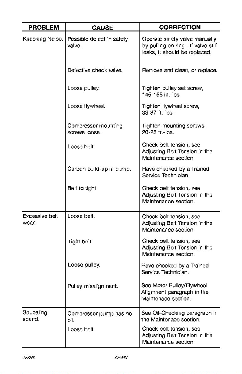
CAUSE
Possible defect in safety
valve.
PROBLEM
KnockingNoise.
Defective check valve.
Loose pulley.
Loose flywheel.
Compressor mounting
screws loose.
Loose belt.
Carbon build-up in pump,
Belt to tight,
Excessive belt Loose belt.
wear.
Tight belt,
Loose pulley.
Squealing
sound,
Pulley misalignment.
Compressor pump has no
oil.
Loose belt.
CORRECTION
Operate safety valve manually
by pulling on ring. If valve still
leaks, it should be replaced,
Remove and clean, or replace.
Tighten pulley set screw,
145-165 in.-Ibs,
Tighten flywheel screw,
33-37 fL-Ibs,
Tighten mounting screws,
20-25 fL-Ibs,
Check belt tension, see
Adjusting Belt Tension in the
Maintenance section
Have checked by a Trained
Service Technician,
Check belt tension, see
Adjusting Belt Tension in the
Maintenance section,
Check belt tension, see
Adjusting Belt Tension in the
Maintenance section,
Check belt tension, see
Adjusting Belt Tension in the
Maintenance section,
Have checked by a Trained
Service Technician,
See Motor l=ulley/Flywheel
Alignment paragraph in the
Maintenaee section.
See Oil-Checking paragraph in
the Maintenace section,
Check belt tension, see
Adjusting Belt Tension in the
Maintenance section,

I_o]i31_']
27-ENG L3__._.9_2
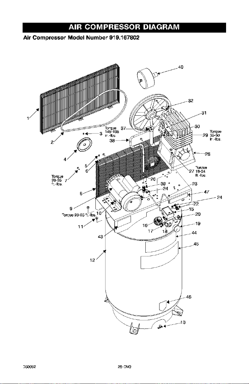
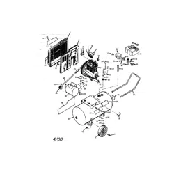
Air Compressor Model Number 919.167802
_20
_19
__44
45
_-)_,.1_32 25-EN_
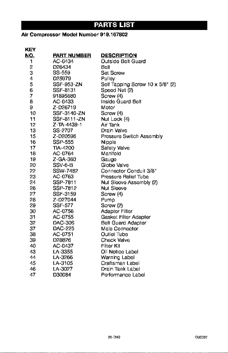
Air Compressor Model Number 919.167802
KEY
NO. PART NUMBER DESCRIPTION
1 AC-0434 Outside Belt Guard
2 D26434 Belt
3 SS-559 Set Screw
4 D25979 Pulley
5 SSF-953-ZN Self Tapping Screw 10 x 5/8" (2)
6 SSF-8131 Speed Nut (2)
7 91895680 Screw (4)
8 AC-0433 Inside Guard Belt
g Z-D2671g Motor
10 SSF-3140-ZN Screw (4)
11 SSF-8111 -ZN Nut Lock (4)
12 Z-TA-4439-1 Air Tank
13 SS-2707 Drain Valve
15 Z-D20596 Pressure Switch Assembly
16 SSP-555 Nipple
17 TIA-4200 Safety Valve
18 AC-0764 Manifold
19 Z-GA-360 Gauge
20 SSV-6-B Globe Valve
22 SSW-7482 Connector Conduit 3/8"
23 AC-0763 Pressure Relief Tube
24 SSP-7811 Nut Sleeve Assembly (2)
26 SSP-7812 Nut Sleeve
27 SSF-3159 Screw (4)
28 Z-D27044 Pump
29 SSF-577 Screw (2)
30 AC-0756 Adapter Filter
31 AC-0755 Gasket Filter Adapter
32 DAC-306 Belt Guard Adapter
37 DAC-225 Male Connector
38 AC-0751 Outlet Tube
39 D28826 Check Valve
40 AC-0437 Filter Kit
43 LA-3355 Oil Notice Label
44 LA-3266 Warning Label
45 LA-3105 Craftsman Label
46 LA-3027 Drain Tank Label
47 D30084 Performance Label
29-EN_ EY3CC9_2
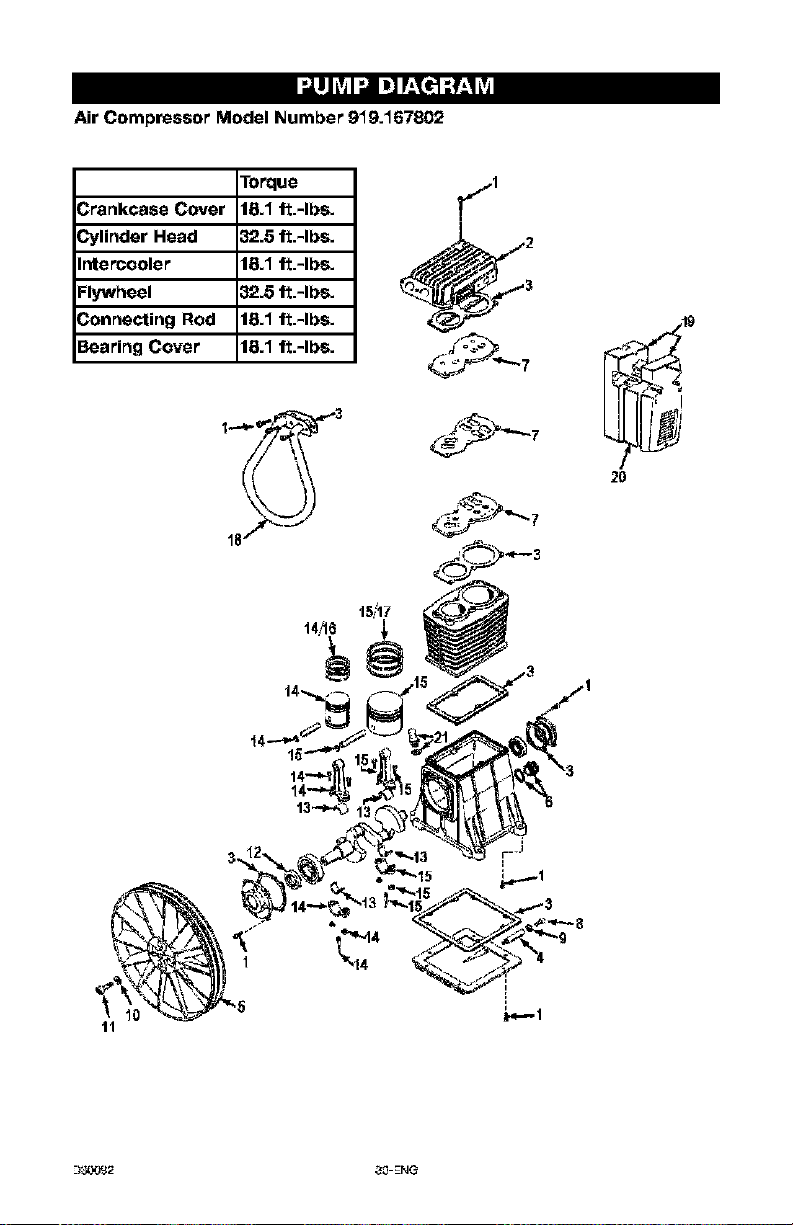
Air Compressor Model Number 919.167802
l"orque
3rankcase Cover 18.1 ft.-Ibs.
_linder Head 32.8 ft.-Ibs.
ntercooler 18.1 ft.-Ibs.
:lywheel 32.8 ft.-Ibs.
3onnecting Rod 18:1 ft.-Ibs.
3earing Cover 18:1 ft.-Ibs.
18
T,_,,I
2O
--I_Y,_2 30-ENG
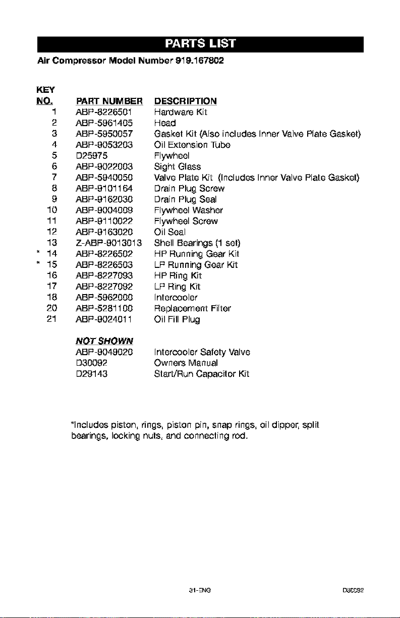
Air Compressor Model Number 919.167802
KEY
NO. PART NUMBER DESCRIPTION
1 ABF=-8226501 Hardware Kit
2 ABI=-5961405 Head
3 ABI=-5950057 Gasket Kit (Also includes Inner Valve Plate Gasket}
4 ABI=-9053203 Oil Extension Tube
5 D25975 Flywheel
6 ABI=-9022003 Sight Glass
7 ABI=-5940050 Valve Plate Kit (Includes Inner Valve Plate Gasket}
8 ABI=-9101164 Drain Plug Screw
9 ABI=-9162030 Drain Plug Seal
10 ABI=-9004009 Flywheel Washer
11 ABI=-9110022 Flywheel Screw
12 ABF-9163020 Oil Seal
13 Z-ABI=-9013013 Shell Bearings (1 set)
* 14 ABI=-8226502 HP Running Gear Kit
* 15 ABI=-8226503 LI= Running Gear Kit
16 ABI=-8227093 HP Ring Kit
17 ABI=-8227092 LI= Ring Kit
18 ABI=-5962000 Intercooler
20 ABI=-5281100 Replacement Filter
21 ABI=-9024011 Oil Fill Plug
NOT SHOWN
ABI=-9049020
D30092
D29143
Intercooler Safety Valve
Owners Manual
Starb"Run Capacitor Kit
*Includes piston, rings, piston pin, snap rings, oil dipper, split
bearings, locking nuts, and connecting rod.
31-ENG L_CC9_2
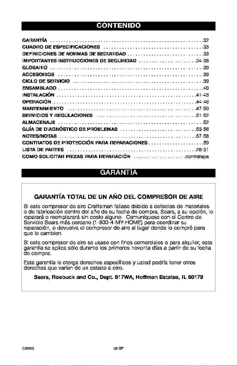
_T_ .......................................................... 32
CUADRO DE ESPECIFICACIONES ...................................... 33
DEFINIOIONES DE NORMAS DE SEGURIDAD ............................. 33
IMPORTANTES INb'TRUOCIONES DE $EGURIDAD ...................... 3_-3;5
GLOSARIO .......................................................... 39
ACOESORIOS ....................................................... 39
CICLO DE SERVICIO .................................................. 39
EN_AMBLADO ....................................................... _0
IN_3"ALACIC)N ..................................................... 41-_3
OPERAOION ...................................................... 4_-_6
MANTENIMIENTO ................................................. 47-50
SERVICIOS Y REGUILACIONES ...................................... 51-52
ALMACENAJE ....................................................... 52
GUi'A DE DIAGN_TICO DE PROBLEMAS ............................. 53-56
NOTES/NOTA,S .................................................... 57-5;5
CONTP, ATOS DE PROTECCION PAPA REPARACIONES ..................... 59
I_ISTA DE PARTES ................................................. 28-31
COMe SOLICITAR PIEZAS PAR& REPARACION .................... c&ntmtap_
_11 :tll _i I r__
GARANTIA TOTAL DE UN A_IO DEL COMPRESOR DE AIRE
Si eete compresor de aire Craftsman fallase debidc a defec_oe de matedales
o de fabricaci6n dentro del aSo de eu fecha de ccrnpra, Sears, a su cpciSn, Ic
reparar& o reernplazar& sin cceto algunc, Cornunfqueee con el Cenvc de
Servicio Sears rn&s cercano (1-800-4-MY-HOME] para cccrdinar su
reparaci6n, c devuelva el ccmpresor de aire al lugar dcnde Io ccmpr6 para
que Ic carnbien,
Si este compresor de aire se usase con fines cornerciales o para alquiler, esta
garantfa se aplica s61o durante Ice pdmeros noventa d[as a pariir de su fecha
de compra,
Esta garant[a le otorga derechos especfficos y usted podda tenet otros
derachos que varfan de un estado a otto.
Sears, Roebuck and Co., Dept. 817WA, Hoffman Estates, IL 60179
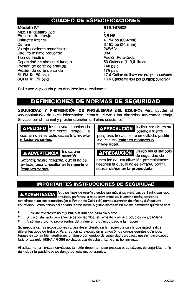
Modelo Ne
M_x. HP des_rrollsdo
Potenois de treble
Oi_metro interior
Ca_ra
Veltaj_oorrierltO morlOf_L_ios
Circuito mlnime r_querido
Ti_ de Fusible
Copseidod de oire en el tsnque
Pr_si6n de Corsede entr_do
Pr_si6n de Corsedo _lido
SCFM @ 100 psig
SCFM @ 175 psig
919.167802
7
5,5 HP
4,134 po (60,4ram)
2,165 po (34,3mm)
240/60/1
30A
Acoidn Reto_odo
80 Golones (I 13,6 Iitros}
140 psi9
175 psi 9
17.4 C_1i_ de libtas p_r puig_ds o._drada
16,9 O_1i_ de libra pot pul_ oJ_ _do
Refierase el glosorio pore descifror los obreviatur_.
SEGURIDAD Y PREVENCION DE PROBLEMAS DEL EQUIPO: Psrs syudsr el
receneoimier, to de esto infermooi6n, heroes utilizodo los sfmbolos mostr_dos sba{o.
81r,,B.seleer el monuol y pr_stsr otenoi6n o diohB_sseooiones.
_ Indioo uno situoei6n de
inminente . Ior[esgo,
ouol, si no es evitods, caus_r_ Io muerte
o lesiones _nos.
potenoislmente riesgos.9, que si no es
evitsds, podrfo r_sultar en Io muerte o
lesiones series.
_ Indi_'._ uns situsoi6n
poteneiolmente
peligroso, Io ouol, si no es evitodo, podffs
resultsr on lesiones menores o
moderados.
_ Ussdo sin el slmbolo
do seguridod de
olorto indioo uns situsoi6n potenoiolmento
riesgoso Is que, si no es evitodo, p_drfs
oausar dodos on Is oro_iedodo.
A _b hoe tipo_ de 9ser_'n ¢_EIo_ _r m_OJ1118$el_td_ ce lijado, a_er "ace,
_ _olsdo, p_fors_o _ ¢cras act videde4__e IQ¢o_8t _Jcci6% _ntie_e_
nlscerisl_ qulmico_ cono¢ do_ (on el E_ado de Califor_ia) co_'o _ssntes de c_JlCer,cefe¢_o_ de
El plomo _iltsr_i_o en _lg_il_ pintLira_ COn base _e #lorno
Smqice cri_tsliz6do provenieilte de lOS18drilJos,el come,to y ot_ pro_u cto_ de _lb_i_ilet_a
• Ars_ico y creme _rovenieilte_ del trat_n_iento Q_lrn_ico d_o 8 Is n_dera
Su d_o 8 _1¢h_.$ expo_i tie ne-$va 48_ dependielldo _e la f_3Lleilcia con la q_e Listed realice
_iferente_ ti_o8 de trab_jo. P_P6 red Licir $u exposi¢i6n 8 Is aoci6_ _e _icho_ age_ _u_rqico_:
t¢absje e_ zoi188 bieil veiltil_da$, y h_gslo con equine de $eguridr_d _proba_o, u_,esiemo'e prccecci6_
fsci=J o re_pirado? MSHA/NIOSFI ap_b_do8 ¢_a_do deba L_;IEzs'0i¢_ her,anli_T_r
AJ utilizar hetrsJl_ie_8$ neLirn_tica$ tsJl_bi6il deben tomsPae p rgc.:sJJcioile8 b_ic_ de 8_jMrid_, 8 fin
_e red,tit Is posibili_ de 4esgo de lesio_e_ pecsonale_r
_-SP EY_CCg_2
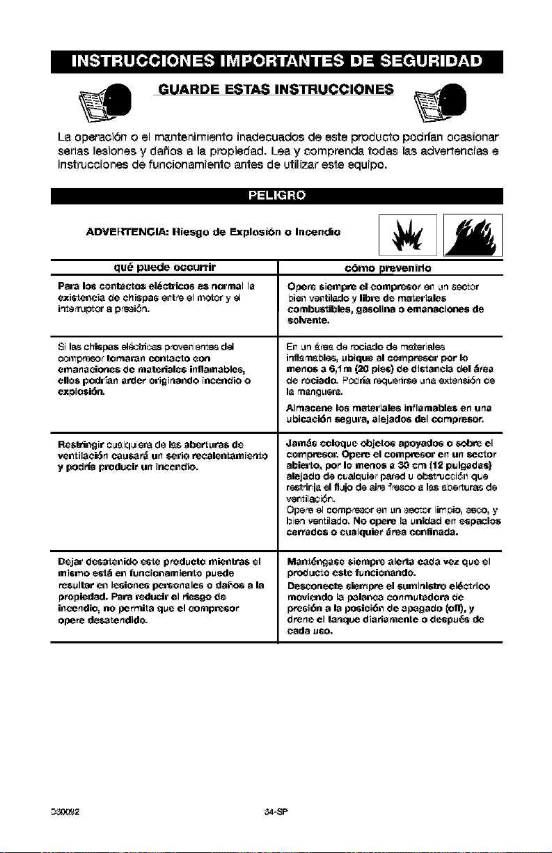
GUARDE ESTAS INSTRUCCIONES
La operaci6n o el manten[rniento inadecuados de este producto petit|an ocasionar
serias lesiones y dafios a la propiedad. Lea y comprenda todas las advertencras e
[nstrucc[ones de funcionam[ento antes de utilizar este equ[po.
'J=lq [_;{I
ADVERTENCIA: Riesgo de Explosi6n o Incendio
qu6 puede oeeurrir
Para los conta_t¢:_ el_.c_icos e$ normal la
existencia de chispas silt _eel n_otor y el
i_e_rLlotor 8 p_si_n.
Si I_s chispa$ el_icas 0_nier_ d_l
Coil_prg8o_tomaran conta_to Con
emanaciorte$ de mat_i_le$ irtilamables_
egos podr[an a_:ler ori_inrJndo incendio o
explo$i6n.
Re$_ringir cusIquiem de Iss aberturas de
ventilaciAn cau_ar_ un serio recalentamiertto
y podrla produci_ un incendio.
Dejar desatenido este producto mienb-a$ el
mismo est_ en funcionamiertto pu_le
resultar en lesiones personales o da_o6 a la
propiedad. Para reducir el riesgo de
in_ndio_ no pe_mita que el Compreso_
opere desatendido.
c45mo prevenido
Opere $iempre el compRso_ en _n _ector
biell velltil_do y libre de materiale$
combustibles, gasolina o emanacic_e$ de
solv_ltte.
En _n _es de rociado de r_steri_Je_
irrflsmsbl6s, ubique al compresor per Io
meno$ a 6,1 ra (20 pies) de distancia del _rea
de rociado. PO_r_8requerirse _lna ex-tensi_n _e
la ¢narl_lef_.
Almace_e los materiales inflaraable$ en una
ubicaci6n _gura, alejados del compresor.
Jamds coloque ¢_jeto_ apoyados o sc_re el
compresor. Opere el coml_resor en un secto_
abier to, per Io meno$ a 30 cm (t2 pulgadas)
alejado de cualctuiet pared u obstruction que
restrir_ia el flujo de airs {_s_co a Iss _bertur8_ de
ver_til_i_r_.
Ope_e el comp_e_or en _n _ector lir_pio, _eco, y
bien _,sr_til_o. NO opere la unidad en _pacio$
cerrado$ o cualquie_ _rea confinada.
Mant@ngase sierapre alerta cada vez que el
3roducto este funcionando.
De,on,ere _iempre el $uminisb'o el6_t _ico
moviendo la palanea conmutadora de
3resign a la posici_n de apagado {olin, y
drene el t_nque diaHa melee o de_pu_ de
--I_,Y,_2 34-SP
'J=lq [_;{I
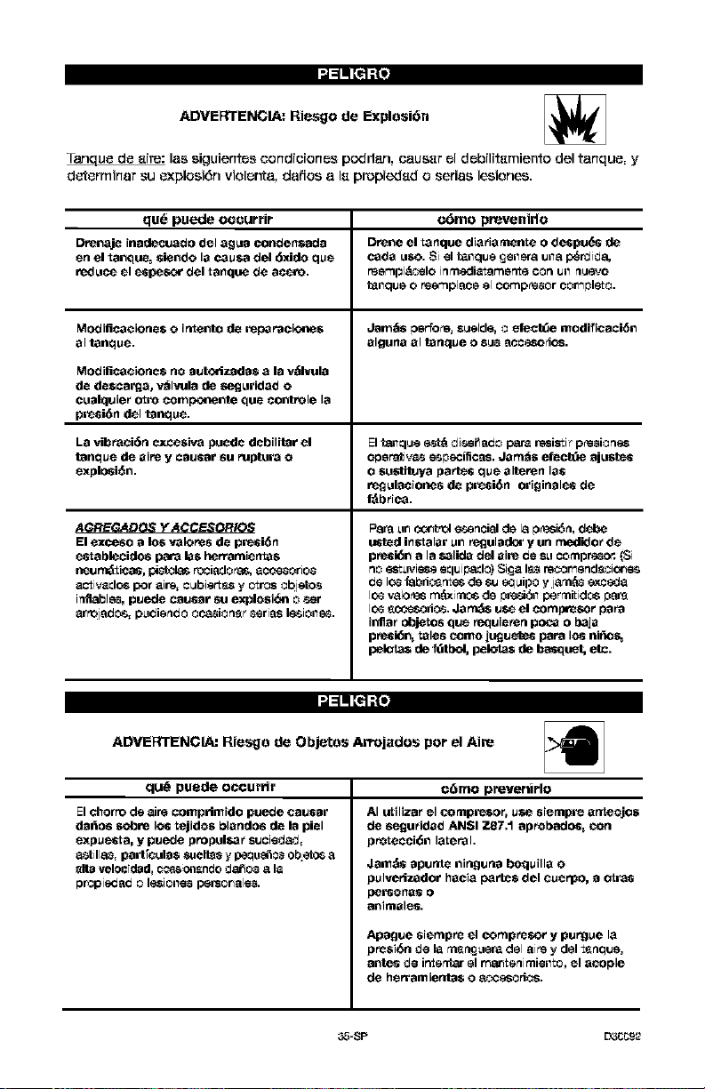
ADVERTENGIA: Riesgo de Explosi6n
Tanau_ d_ erre: las siguiente_ _ondrcrone_ podflan, causer el debrlrtemiento del tanqu_, y
d_rminar _u _×plosi6n violer_a, dafios a I_ propieded o serias lesiones.
qu6 puede ocourrir c_mo prevenirlo
Drenaje inadecuado del agu_J condensada Drene el tanque diaHamente o despue_s de
en el tanque_ _iendo la c3usa del 6xido que c_da uso. Si el t_llque £eller8 u118p_rdida,
reduce el espes_" del tanque de acero, reer_pl_lo inmedi_tsr_erlte con _11_uevo
t_ilqu8 o re_pl_lc8 _1co_p_8or cor_pleto.
Modificacione$ o intento de repa Pacic_e$ J_m_s per_ore, suelde, o efect_e modificaci6n
al tanqu_, alguna al tanque o sub _cceso4os.
Modifica¢ione$ no _Jut¢_iz_d_J$ a la v_lvula
de de$car_a, v_lvula de seguridad o
cu_Jlquie_ otto compo_ente que controle la
pRsi6n del tanque.
La vib_aci6n excesiva puede debilitar el Elt_que e_t_ d isei_e_o para resisti_ p_s_iones
tanqu_ d_ aire y c_Ju_Jr su ruptura o oper_iv_ e_pec_cets. Jam_$ ef_ct_ ajustes
_xplosi6n. o $ustituya partes qu_ alteren la_
regul_ciones de pRsi6n origin_les de
_b_ica.
AGREGADOS Y ACCESORIOS
El exceso a los ¥_1of_8 de presiSn
establecidos para la$ her_amienta$
_t_'lJrn_iP.,as, pib"b'jl_ n+jcJ_J0_, _c_$orio$
activados For airs, cubierts,s y otros objetos
i_flabls_, puede causar su explosi_ o ser
t_r_ojedo_, pLidiefld0 0P.m_i0n_r _riP+s le-_ioll_.
Para _n ccitt _cl esencial de 18p_i_, debe
tinted instalar un r_ul_ y Un medi_o_ d_
pmsi_n a la salida del aire _e SLIcomprs+o_ (Si
no _+_Lr_ieseeq_ip_J_ Si£t_ I_ re_r_end_ic4_
_e Io$ _bri_n_es de s_ eQuipo y jsm_ exceda
Ic_ vsIo_ rn_ximo_ de pr_ll p_rmi_ido_ p_
Ic_ _es_ri_. Jarn_ u_ el comp_sor papa
inila_ objetos que requieren poma o baja
p_i_n_ tales ¢omo jt_uetes papa los niftos+
pelotas de fdtbd, pelotas de bas_!uet, etc.
'J :1 II [_ ;:II
ADVERTENGIA: Riesgo de Objetos Arrojados por el Aire
qua"puede occurrir c6rno prevertirlo
El chor_o de t_ir+ comp_imido puede causar
da_os sc_re lOStejido$ blandos de la piel
_xpu_a, y puede propul_3_ s_cied_,
_tilla$, part_ul_$ suelt_s y p+queiSo_obieto_ a
_na velocidad_ c_-_so_l_ndo d_o8 8 h_
pr_pi_P+d o I_iolle8 personsles.
AI u_iliza_ _1 _rnpmso_, use siempre arlteojos
de seguHdad ANSI 7.87.1 aprobadom+ _n
pro_ecci6n lateral.
Jam_s apurtte ninguna boquilla o
pulYerizador hacia part_$ del Cuerpo, a otras
per_ona_ o
a_imal_.
Apague siempm _1 compres+_r y purgue la
pmsi+n de la mmm£ueradel 8i_ y del tmmctue,
a,lte_ d{_ i_ritar el r_sJ_r_imi{_il_o, _1 acople
de h_rramierita$ o 8¢.¢esorios.
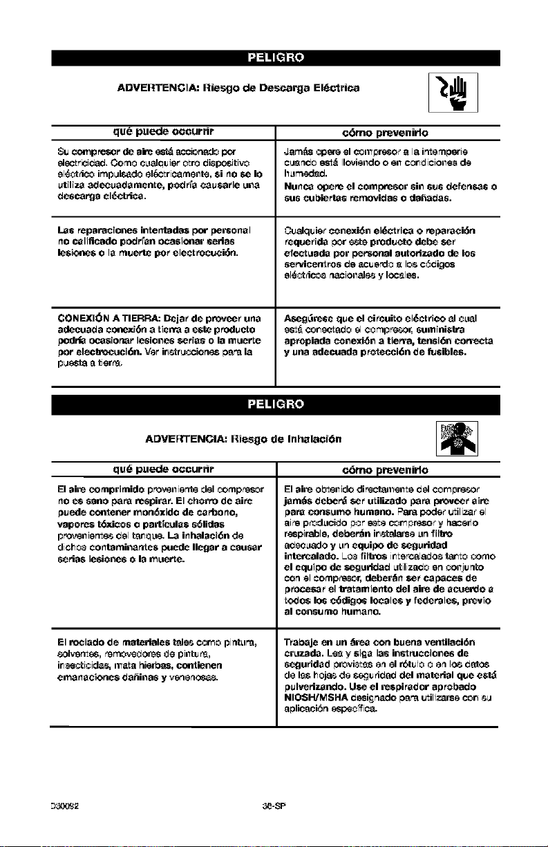
ADVERTENCIA: Riesgo de Descarga El{_c_rica {_/F
qu6 puede occurrir c_mo prevenirlo
Su cc_mp_or de ak_ _ accion_do pc_ Jam_s opsre el COil_pr_ a la ir_empsrte
_lg_'trici_d. Como OLtalduJet 0tr0 dispositivo Cu_ndo est_ Ilct_ielldo o ell coredioiolle$ de
el_._rico impuls_do el/_'Lrio_mellte, $i no _e Io hLimedsd.
utiliza adecuadamente, podrfa _ausafle una Nunca c_ere el compresor sin sus def_ne_s o
descarga el_trica, sus cul_ie_tas Pemo_das o da_adas.
Las Peparaeiones intentada$ p_r personal Cualquie_ conexi6n el6ct flea o reparaei6n
no ¢alificado podrran ocasic41ar serias Pequefida por este produeto debe se_
lesic4_e$ o la muerte po_ electrocuei6n. _.fect uada pot personal autorizado de los
servicenvos de _cuerdo _ I_ c_digos
el_¢_rico_ R_ioI1_J_ y Ioceles.
GONEXION A TIERRA: Dejar de proveer una Aseg_Rse que el ei_uiLo el_ctrico al ¢L_al
adecuada cm_exi_n a tierra a este produeto est_ coronado el comprssor, suminisl_ra
pedria ocasionar lesiones series o la muerte apropiada cone_d_n a tierra, tensi6n eorre_a
pot elecWocuci6n. Vet ir_struocion_ para la y una adecuada pro_ecci6n de fusible$.
p ues'_aa tiers.
ADVERTENGIIA: Riesgo de Inhalacidn
qu_ puede occurrir c_Smoprevenirlo
El air oomprimido provellierr_ ¢lel _mpr_$or
no _ sano pe_ respira_. El ehorro de aiPr_
puede cozener mon_ido de carbono,
vapoPe$ t_.icos o part_ula$ s61ida$
provellie_ del t_u_q_le.La inhalaei6n de
dicho_ contarninantes peede Ilegar a causar
seria$ lesiones o la muerte.
El rociado de mat_riales t_J_ torso pintLira,
801ve_, _Ov_dOr_$ de piiltiJ_,
i_oti¢id_, n_t_ hierb_ts, c¢_tienen
em_n_eione$ d_il_a6 y retie rlor._.
El air ol_ellido dir_c'_al_ellte del cor_pr_or
am_s depe_ se_ utilizado papa p_ovee_ aire
)ara eonsumo humano. Par_ pode_ utilJz_ el
_i_ p_dLioido pot _e oor_pr_o_ y hacerlo
respireble, debe_n i_alarse Linfilb_
_ecLlado y Lin equipe de _guridad
inte_alado. LO_ filbo$ i_terc_l_os ta_to _mo
el equipe de _guHd_d Litiliz_o en _lljunto
oon el oomp_or, deber_n _ c*_pece$ de
)_oce_ el b-at amiento del awe de aeuen:lo a
todo$ los c_digos locales y fedePales, previo
al P._o_t_lJRiohllm_rio.
Tfabaje _1 un _re_ Con buena ventilaci_n
cruz_da. Le_ y $if_a la_ in_t mceiones de
segu_idad pr_vi_s en el r_tulo o en Io_ d_tos
de l_s h_as de s_ju _id_ del materlal que est_
)ulverlzando, Use el respi_dor ap_ol_ado
NIOSH/MSHA desi_n_do papa utiliz_rse co_ _u
aplicaci_n sspe¢_ioa,
--I_Y,_2 _-SP
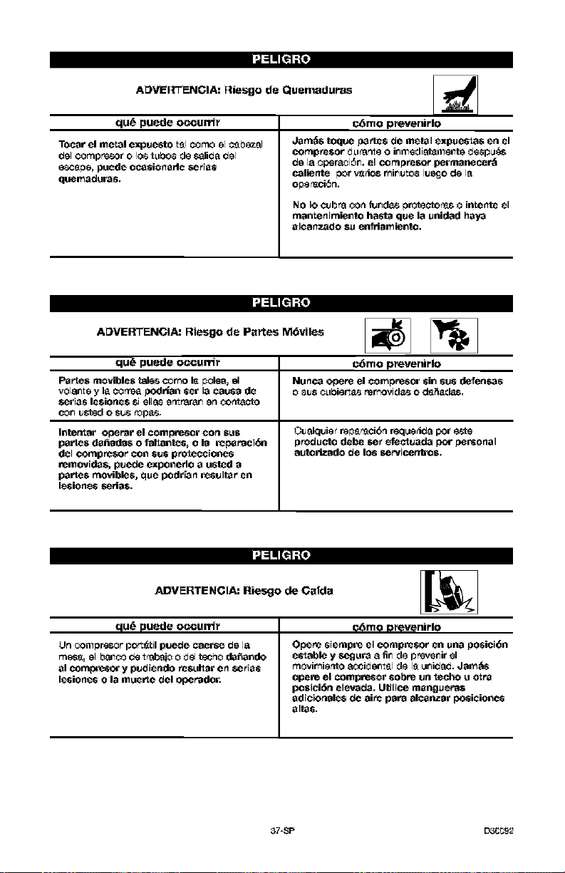
ADVERTENCIA: Riesgo de Quemaduras
qua"puede occurrir
Tocar el metal expuesto tsl como el C_b_zal
gel compnssor o los tL_bo_ de s_lida gel
e-_c_pe, puede oc_sionarle eeHas
quemaduras,
c6mo p_vertirlo
dam_$ toque parte$ de metal expuesta$ en el
compr_$or dL_a_e 0 ir_mediatamente de_pu&s
de la oper_i6r_, el comp_sor per manecer_
caliente por vsrios r_ir_uto_ lumjo de la
NO Io cubra _n fur_d_ protecto_ o intentc el
rnantenirniento hasta que la unidad haya
aleanzado su e=_riamiento.
ADVERTENGIA: Riesgo de Partes M6viles _)
qu_ puede occurrir c6rno prevenirlo
Parte$ movible$ tal_s cor_o I_ polea, el Nunca opere el compresor sin sus d_erl_6
volar_tey la corrsa podHan set la causa de o _us eL_biert_._rer_ovid_._ o d_Sadas,
_r_rias le$ione$ si _11_ e_rarar_ e_ _cto
cor_u_d o sus rop_._,
Inte_ar operar el compresor con sus Cualquie¢ reps_ci6n req_erida por _te
partes da_adas o faltantes, o la reparaci_ producto debe _e_ efectuada p<wpersonal
del comp_$or con sus pro_ecciones autorizado de los _ervicenbos.
remo¥ida$, puede exponeflo a usted a
partes movibles, que podrian Rsultar en
lesiones se_a$.
ADVERTENCIA: Riesgo de Gafda _._
qua" puede oc_urrir c6mo omvenirlo
Un _113pr_ff port_til puede caerse de I_
m_= el b_o d_ ±_d_io o gel t_ho da_ando
al cot np_e_¢_ y pudiendo r_sult_r en _ias
lesiones o la muerte del operador.
Opere siempre el comprr_$or en una posiei6n
e_table y segura a fir_de pnsver_irel
movir_ie_to _!_ciderl_l d_ I_ _idad. J_m_s
opere el compresor sol)re un _echo u o_ra
posiei6n elevada. Utilice manguera$
_dieiort_l_ de aiPr_p_r8 alP._llz_r po_i_io_e_
altas.
37-SP L33CC9_
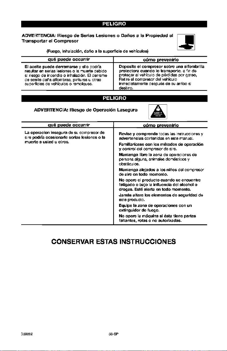
•J_ q[e];(i
ADVE_ENC;IA: Riesgo de S_r_as Lesiones o Dafios a la Propiedad al
Transportar el Compresor
_Fucgo_ inhalaci6n, da_o a la Supcrficie de vehfculo$)
qu_ puede occurrir c_mo prevenirlo
El aceite puede derramaPse y ello poc_r'a Deposite el compRsof sol)re una alfombrilla
resultar on ssria_ lesione-_o I_ musrte debido protectora cuando Io l_anspor te. a _111d_
_1rie_go de irl_lldio o irlllaJ_ci_ll, El der_rne protecjer _1vehicLilo de p_rdid_s por _oteo,
de eceite dat_a _;_11_br_ pilltUeR8U L_r'a_ Retire el O011_Dr_r del vShlcLIlo
_u]_erli¢ies de vehicLilos 0 _ernol_ue_. irlll_Gd i_ll_ellte d_pLl_ (_e _lJ _rr_bO _1
d_tillo,
:,l=lq [_1;{_
ADVERTENCIA: Riesgo de Operaci6n Lasegura A
qu_ puede occurrir c_Smo prevenido
L_ op_r_cion irls_gura de SIJCOil_D_or de
e_s podr ta oca$ioe_arle serias lesiones o la
mu_rte _ usted u otPos,
Revise y contprenda _od_ I_ in_Lruccioile_ y
Familiarlc_se con los m6todos de ¢f}_raci_n
y ContrOl c_l _r_pr_or de _ire.
Mantenga lil0_ I_ zona d_ operaoioile_ c_
pe_n_ alg_il_, _nir_ales dor_e_ti_ y
ObSt_CLIIOS.
Mantenga _lej_dos a Io_ niffo$ d_l ¢or_pn_._r
de aire en todo ntomento.
NO ope_ el produ_to cuando _ e ncue n_L_
fa_gado o bejo la influ_ncia del _lcohol o
dn_a$. Est_ _l_rta en todo momento.
Jant_$ altere los elemento_ de seguridad de
e_Le prc_cto.
Equip_ I_ zon_ de of}_r_cicetes con un
exUnguido_ de fuego.
NO opere la m_¢!uin_ $i 6$ta _iene parte$
f_l_ant_$_ rota$ o no _lutorJzad_l$.
CONSIERVAR IESTAS INSTRUCCIONIES
--I_Y,_2 _-SP
Ft_milierTG_s_con lossiguiente._tdrminos,
antesde opetarI_unidad:
GFM: (Oubiofeetper minute)PiesoObioos
por minute.
8CFM_ (Stardard cubic feet per minute)
PiSS c0bJcoe est_ndar par minuto; una
unJdad de medJda qua permite medir la
oantided de entrega de sire.
PSlG: (Pounds Per Squ_e inch Gouge) -
PresJ6n manometrJce creative en IJbras par
pulgade ouedrada; una medide de la
ent_a de sire.
G6digo do certiflcaoi_n: los pPoduotos
qua usan una o m&s de lee eiguientes
maPcas: UL, CUL, ETL, CETL, hen sido
evaluedoe pot OSHA, laboratorios
independientes oertifioados en seguridad,
y teOnen los es_ndar_s sus_fiptoepot
Underwriters L_boratoriee Standards for
sai'aty.
PresiSn minima de aorta: Cuendo el
motor est_ epagado, la ptesi6n del tanque
de site baja a medida qua u_ed contin0a
usendo su acoesorJo. Cuendo Is presi6n
del tenque baja al velar fijado on f_brica
coma punto bejo, el motor volvon_ a
ertancer _Jtom&ticemente. La presidn
baja e la oual elmotor atranca
eutom_ticemente, se llama ptesi6n
"minima de carte".
Presi_n m_vJma de carte: Cuando un
compresor de aire se enoiende y
comienza a funoionar, la ptesi6n de _re on
el tanque oomienza a aumentar. Aumente
haste un valor de presi6n alto fijado on
f_brice antes de qua el motor
eutom_ticemente se apague proteqiendo
e su tenque de aire de presiones m_s
sites qua su oapacidad. La presidn alto a
Is ouel el motor se apega se llama presi6n
"m_ima de carte'.
Ramel: Ci_uito el_trico qua tranepotte
eleotrioidad desde el penal de control
hasta el tomacorriente.
C6mo bloqueer Is alimentaoidn:
Coloque un oerPojoon el interruptor de
elimentaci6n pera impedir qua alguien
poeda enoenderlo,"
Ests unida_t8s sufi¢iente par_ abaslecer de ene_|a ell'trios a lossiguientes aS_SOrt0Sr Esto_ Se
eneuentr_n disponibles a travds dd cat_i[o£o pare herramrent_s e]dotrtcasy manuales, en
eualqurera de losoomeraios que msntiene la lines oomplet_ de SEARS.
Ac_asorios
• FiltrO on l|nee
• Et_tade do aiPe a neum_ioos
• Jueqoe de oonectores r_pidos (varies
tamafios)
• Reguladores de ptesi6n de aire
• Lubrioadores de niebla de aoeite
• Men_uera de aire:
1/4', 5/18,3/8" o 1/2" D.I. en verJ_
medidas
Esta bombs compresom de aire es topaz
de funoionar oontinuamente, sin embargo
pare prolonger la vide Otil de su
oompresor de air_ee recomJenda
mantener un 01010promedio de servioio
qua cecile entre el 5096 y el 75%; ella
signifies qua la bombs compresore no
deber|a trabajar m&s de 30 e 45 minutes
par hera.
_-SP L_CCg_2
Contenido de la Caja
I - Compresor de sire
I - Bolesde piszes_x_nteniendo
Iosi_uisnte:
1 - Msnual dsl operador
1 - Msnual de pi_s
4 - Arandelas de 5/8 plug.
Herramierdas necesarias pars el
ensemble
1 - liars de tubs o de boca de 9/1{; plug.
taladto el_trioo
1 _ el_otrisos talsdres
Desembalaje
1. Extrsiga tedo el embalajs
Podl=_ Mr
rle_s_lrlo
apuntalar o seportar un lads del equips
el exb'aer la plataforrna, porque el
eompresor de airs tender_ a inclinsrse.
2. Exttsiga y desserts los (4) tomilles y
atandslss que sujetan el sompr_sor s
la pleteforma.
3.
Con la eyuda de otra persons,
temueva cuidsdossmente el
sompr_sor de airs de su plstsforma y
sol6quelo sobre une pletsforma
nivelads.
PaPa agregar aceite ala bombs
aceite. AI reeibir el compresor de airs,
puede haber un pose de aceite en la
bombs. Este se debe a lee pruebes en
la f_brtca y no signifies que la bombs
tiene aceite. No intentar operar este
eompresor de airs sin antes hsberle
agregado aceife el c_rter. Pueden
ocurrir series da_os, inclusive con
operaciones limitedss, si no se liens de
aceite y no se asiente correc_amente,
Cereiorerse de seguir euidadosamente
los procedimientos pare el ar_anque
inieial.
viseesidad mOltiple come 10W80 en
ning_n compresor de sire. Este_
aceites dejan depdsitos de corbo°o en
componentes erRicos, reduciendo el
rendimiente y la vide dtn del compress,,
861o user aceite pare eompresor de
sire.
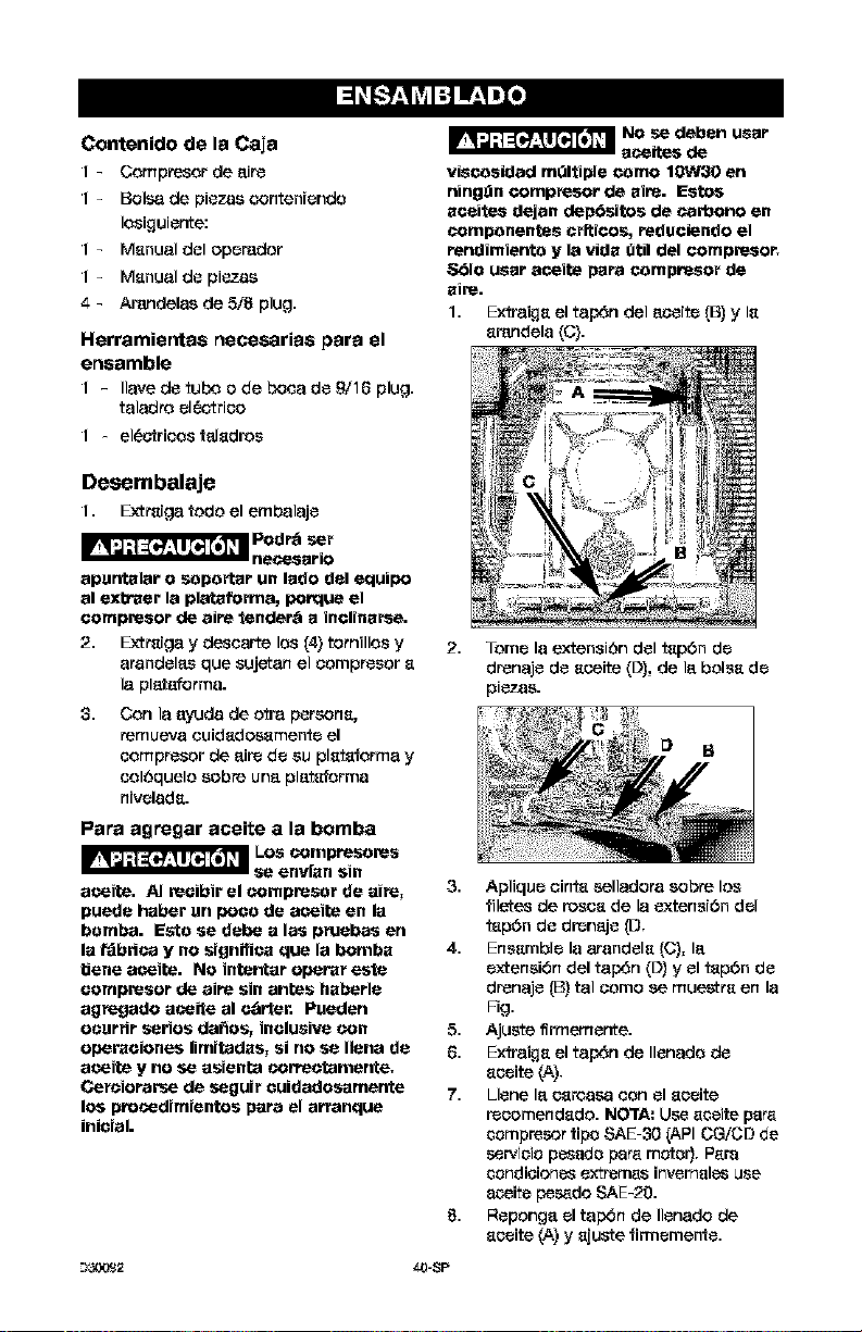
1. Extraigs el tap6n del eosite (B) y Is
srandela (C).
2. Tome la extension dol tsp6n de
drenajo do soeite (D), de le boles de
pi_o.
_-SP
3. Apliquo oints selladora sobre los
filetes de rosos de la oxtensi6n dol
tsp6n do drenejo (D,
4. Ensemble la arandels (C), le
oxteneiSn del tap6n (D) y el tsp6n de
drenajo (B) tel some se musette en la
Fig.
5. Ajuote ffrmemente.
6. Extraigs el tap6n de Ilenado de
sooite (A),
7. Lions 18_osroasa con el sooite
reoomendsdo. NOTA: U_ _coito psr_
compresor tips ,SAE 30 _APICGiCD do
._ervioio pess_o psr_. motor). P_.ra
condioiones extremes invemsles use
soeito pesado SAE-2O.
Roponge el tap45n de Ilonado de
sooite (A) y sjuste firmomento.
Ubicaci6n del compresor de aim
Instale _1oompre_r de sire _n un_
zon_ limpis, coca y bien ventilads.
Instale el oomprecor de sire _ una
distancis no menor de 12 plug,
(30 ore) de Is pared u otrss
obstrueeiones que pudiosen ir_ert_rir
con el flujo del sire.
Instale el eompresor de sire Io m&s
ceres posible del sitio de
alimentaei_n el6ctrie_, s fin de evitar
el uco de Islgas ext_nsionesde
eableado el6otrieo. NOTA: L_S
_'XtelqSioIq_'Sel6_riea_ demssisdo
la_ss pueden causer una e_ld_ de
tensi6n perjudieial pars I_
alimentaei6n del motor.
El filtro de sire debe mantenerse libre
de obstruosionos que pudiecon
tedueir el flujo del sire al eompresor.
Anclaje del compresor de aire
La vibraoi6n
ex_siva psede
debnitar al tanque de sire y causer su
explosi6n. El oompresor debe ester
montado adecsadamen4e,
El ¢_omprecor de sire DEBE ostsr
abulonsdo a uns superfieie s61ida y
nivelads.
Elementos rleeossrios;
4 - Tarugos psr_ snel_je_ en
cemento (No Provistos)
4 - Tornillos tirafondo de 3/8 plug.
eapaees de Ileosr los tslugos
pare anelsje en eemento (no
provistos)
4 - Arandelas 5/8 plug. (en I_ bolss
de piezss)
CuSas(enosco de set
ne_sarfo)
1. Instale el eompresor do sire sobre
una superfieie sSIida y nivel_da.
2. Marque la superfieie utilizsndo come
pier, ilia, los orifieios existentes en las
patss del ¢_omprosor de sire,
3. Peffore la sup_rfieie, a fin do petletmr
los refuges papa anolaje en el oemento.
Coloque los tarugos en el cemento.
4. Hsga eoineidir la alinosciOn de los
orifieios de Is superfieie, con el do las
p_tss del ¢_omprosor de sire,
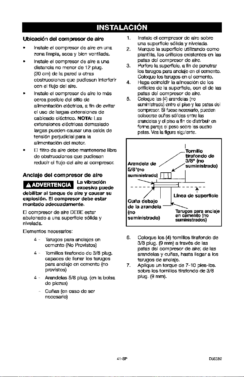
5. Coloque i_s (z.)ar_nde[as (no
sumini_rado)entre e[ pisoy las pates de]
compresor. Si fuese necesario, pueden
oolose_e cu_ s6[idas entre las
e_delas y el prco s fin de drs_ribuPAn
forme pareje 81peso sob_eias cuetre
pet,s. Vee Isflgur_ siguiente.
I
-.Tomillo
_- tirafondo do
Arandelade _ _s3/ugmi_ °. -.
5/8 '(no _ISU SO'aC:IO)
suministxado} ._:::_. ..........J
..... :___C__
_n_a de _u_r'neie
OuRa debajo
do la arandela _
{no Tarugos pars sn_,',lsje
en eerrlerlto no
suministrado) sum n strsdos)
6. Coloque los (4) tornmos tirafondo de
3/8 plug. (9 ram) a trav_s do I_._
patss del eamprosor de air_; de Iss
srandelas y eu_ss, hasta Ilegar a los
ts_ugos de snelaje.
7. Aplique un torque de 7-10 pios-lbs.
cobre los tomillos timfondo do 3/8
plug, (g ram}.
_1-8P L33_£2
Instrucciones papa la conexi6n
el_ctrica
_ Riesga de Descarga
Eldctrica. Una oonexi6n
a tierra inadaouada puede ooasionar
electroouci6n. I.as conexiones deborah
sar e_=ectuadas par an elec_ricista
oalifioado, pars oumplir can los o6digos
aldctricos ,aoional y local.
Aries de _eotuar las conexloncs, url
eleotricista calificado dcbc conooer Io
siguiente:
1. Que el valor promedio del amperaje
en la caia eldotrioa sea €l adecu_o.
Par_ obtencr dicha informaci6n
deber_ re_rirse a la hoja de
espeo]flcaciones del manual de
piezas que se cncuentra al prinoipio
de este manual,
2. Que la Ifnca de suministre €leotrico
tenga id_ticas caraoter|sticas
el_otricas (voltsje, oicles, fase.s) que
las del motor. Para obtcner dioha
informaci6n dcbera referirco a la
placa de idcntiflesoi6n del motor,
ub[csda sobre el IstereJ dal mismo.
NGTA: La conexi6n electrioa debe
corresponder al mismo voltaic indicado
cobre la plaes de identificaci6n del motor
mas o menes 10%. Par_ [nformaree
acerea de las extensiones y calibres de
cable recomendadB.s y m_xima extenal6n
del cireuito, dcbera referirco a los oSdiges
locales; un cireuito subd[mensionado
origina una oa|da elcvada dal amperaje y
un recalentam[ento del motor.
;'::gg:
EI6ctrioa, La oortexi_n el6c'trioa debe
estar ubicada fuera de superficies
oalientas, tales coma silenoiadores de
escape, tubas de salida de
oompresores de sire, osbezales o
oilindros.
INSTRUCCIONES PARA
CONECTAR A TIERRA
E_€ artefaoto dcbe concotaree al terminal
met&lico de un si_cma de oableado
perrnancnte a tierra para eqalpes o al
terminal del artefaoto.
La conexi6n a tierre est_ olarementc
indiesda cobre el compresor.
Sistema de distribuci6n de sire
Riesgo de
Explosi6n. Los
tubas de pl;_ioo o PVC no ban sido
disefiados papa usarlos con aim
comprimido. Independientemente de la
qua est6 indioado coma especifioaci6n
de p_si_n, las oanerlss de pldstioa
pueden explotar debido a la presi6n del
sire. Utilice solarnente co_os de metal
pera los ramales de distribuoidn.
I_ si_aicnte imagen represer',ta un
si_cma t|p[_'_ de distribuci6n de alre. L_S
siguientes son pautes para tener prescnte
al montar el sistema de distribuci6n dal
compresor de alre.
Ut[l[_,_carlo de la misma medida que
el de la salida dal tanque de aire.
Una esficr|a demasiado an_esta
restringira el paso del alre.
S] la oafiefla t[enc m_s de 100 pies
(30 m) de Iongitud, utilico la mcdida
inmcdiata superior.
Entierre la caCierfs pot debajo de la
Irnca de _,ongelamicnto y ev[te
hueoos cn los que la _,ondenesci6n
sc podiese acumular y _,ongelar.
Ef_ot0e pruebas de presi6n antes de
cobrir la oaCierla, a fin de B.scgurarsc
que todB.s las uniones de la m[sma
sc encuentren I[bres de fugas.
Se recomienda la instalaoi6n de un
acoplamiento flexiblY, entre la salida
de descalga del alre y la Ilne_
principal de distrfbcoi6n del mismo, a
fin de aliviar eventuales v[braciones.
NOTA_ I_ v_lvula de corte no se
suministr_ con esta unidad. Oebe
comprarse per separedo.
Se recomienda la instalaoi6n de un
scgundo regulador para el control de
la prealSn del aire. La presi6n de
salida del tanque es - usualmentc
dcmas[ado alta para las herremicntas
indMduales de acoi6n neumatioa.
--)_2 4-2-$P
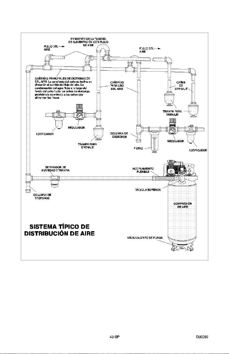
_ ER_?_ pp] 1,4CI_J_S DE D_o'rRIE_C _t_
dlr_, _ ;41_e_!l_ _1 Ilulo d_ _tlr_ _
tdlrr_'_t, _ I_ _n_,_
DELAJRE
C_LIJM_A DE
C'-__EC440_
"FRAVF_ _F_ --
TR_d_p_ V-_q_
\
CC_M_D_
SISTEMA TiPlCO DE
DISTRIBUCION DE AIRE
f
_AI_E
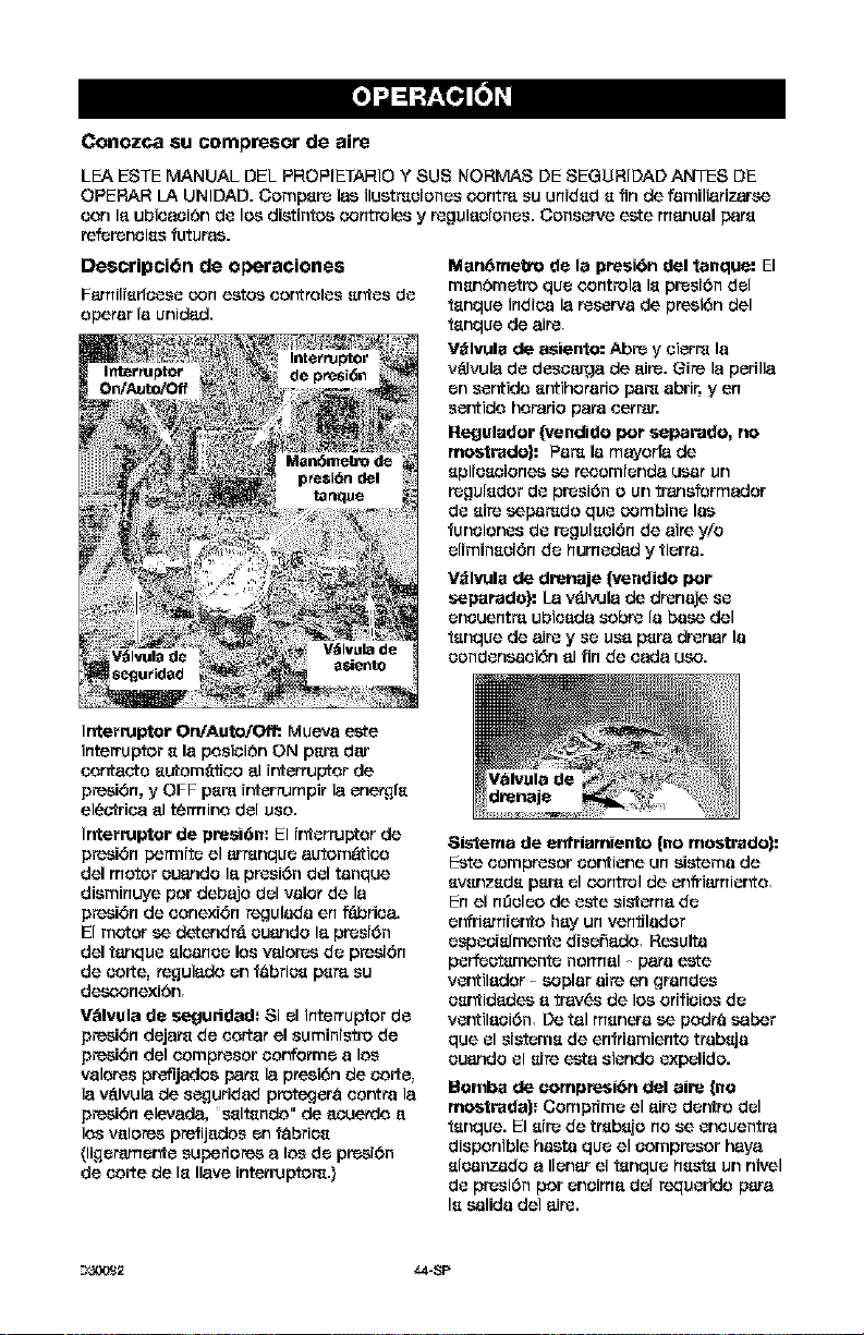
Conozca su compresor de aire
LEA ESTE MANUAL DEE PROPIETARIO Y SUS NORMAS DE SEGURIDAD ANTES DE
OPERAR LA UNLOAD. Cempsre las ilustmcienes ¢_ontra su unidsd s fin de familiatizarsa
Con 18,ubies,oi6n do los distintes c_ontreles y regulacienes. Conserve este manual bats
ref_reneiss futures.
Descripci6n de o_raciones
Fs-milrsrleese con estes eer_reles sr_es do
epetar la unids,d.
Ms,n6ms,tro de 18,presi6n ds,I tanqus,: El
msn6m_tr_ que _x_ntrels, Is presf6n del
tanque indies 18,reserve de presi6n del
tanque de 8,ire,
V_lvuls de 8,sie,_o: Abre y eiarm la
v_lvuls, do desesJ,'qs,de 8,ire. Oire 18,perills,
on sentide s_ihetarie pare abri5 yen
ser_ide horatio bare carter.
Reguls,dor {vs,ndido per ss,parado, no
mostrado|: Pare la ms,yet[8, de
spl;eseienes se recem;ends, U_St un
regulsder do presi6n e un transforms,dot
do sire sabamde que Combine las
funeienes do regulsei6n de 8,ire y/e
eliminsei6n do humeds,d y tiarta.
Vdlvula de drens,je |vendido per
seps,rs,de): La v&l_JIs, de drenaje so
encoantra ubies,ds, Cobre la base del
tanque de 8,irey so uss, pars, drens,t 113
eendensaei6n 8,1fin de es,ds, use.
Interrupter OrVAuto/Off:. Mueva este
interrupter s la pesiei6n ON psr_ dar
Cents,ere sutem_ti_o 8,1ir'_artupter de
presi6n, y OFF psra ir_arrumpit 18,ene_fs
el_ctries, 8,1termine del use.
Interrupter de presi6n: El ir'_arrupter de
presi6n permite el armnque 8,utem&tico
del meter euande 18,presi6n del tanque
disminuye per debs,je del valet de 18,
presi6n de Conexi6n _ulada an fabrics,.
El motor sa detendr& euande 18,presi6n
del tanque sleanco los vs,ler_s do presi6n
de eerte, re_juls,de on f_bries psr8` su
de_onexi6n,
Vblvuls, de segurtds,d_ Si el interrupter do
presibn dejs,re de Corts,t el suministro de
presi6n del Comprecor Cor#etme a los
valeres prefijades bats 18,presi6n de eerie,
18,vdlvuls, de seguridad pretegar8 eer',tta 18,
presi6n elevs,ds,, ssltsnde" de 8,cuende 8,
los vs,leres prefijs,des on fSbries
(ligerarner_e superieres 8,los do prosi6n
de eerte de Is 118,reintarruptere.)
•_$istems,de 8,nfris,mis,nto (no ms,strado|=
Este Comprecor Cor'_iane on sistema de
svsnzsds psra el c_ontrelde enfri8`mier_e,
En el n_elco de este sistems, do
er'#riatnier'_e hs,y un vantilador
espcoislmente disefis,de, Results
perfcotsmente nerms,I - bate este
ver',tils,der - Copier sire en grandes
esr_ids,des 8_trs,v_,s de los efifieies do
ver',tils,oi6n, De ts,I manara sa pedro saber
que el sistems de enfdamiante ttabsja
euande el sire ests, siende expelide.
Bombs de oompfesi6rl ds,I 8,ire (no
mostrads,): Cemprime el 8,ire der_ro del
tsnque. El sire de trebsje nese eneuentrs,
dispenible haste que el Compresar hs,ys,
slsanzade 8,Ilanar el tanque hssts un nivel
do presi6n per eneims, del requaride pars,
Is salida del 8,ire.
--I_2 _$-SP
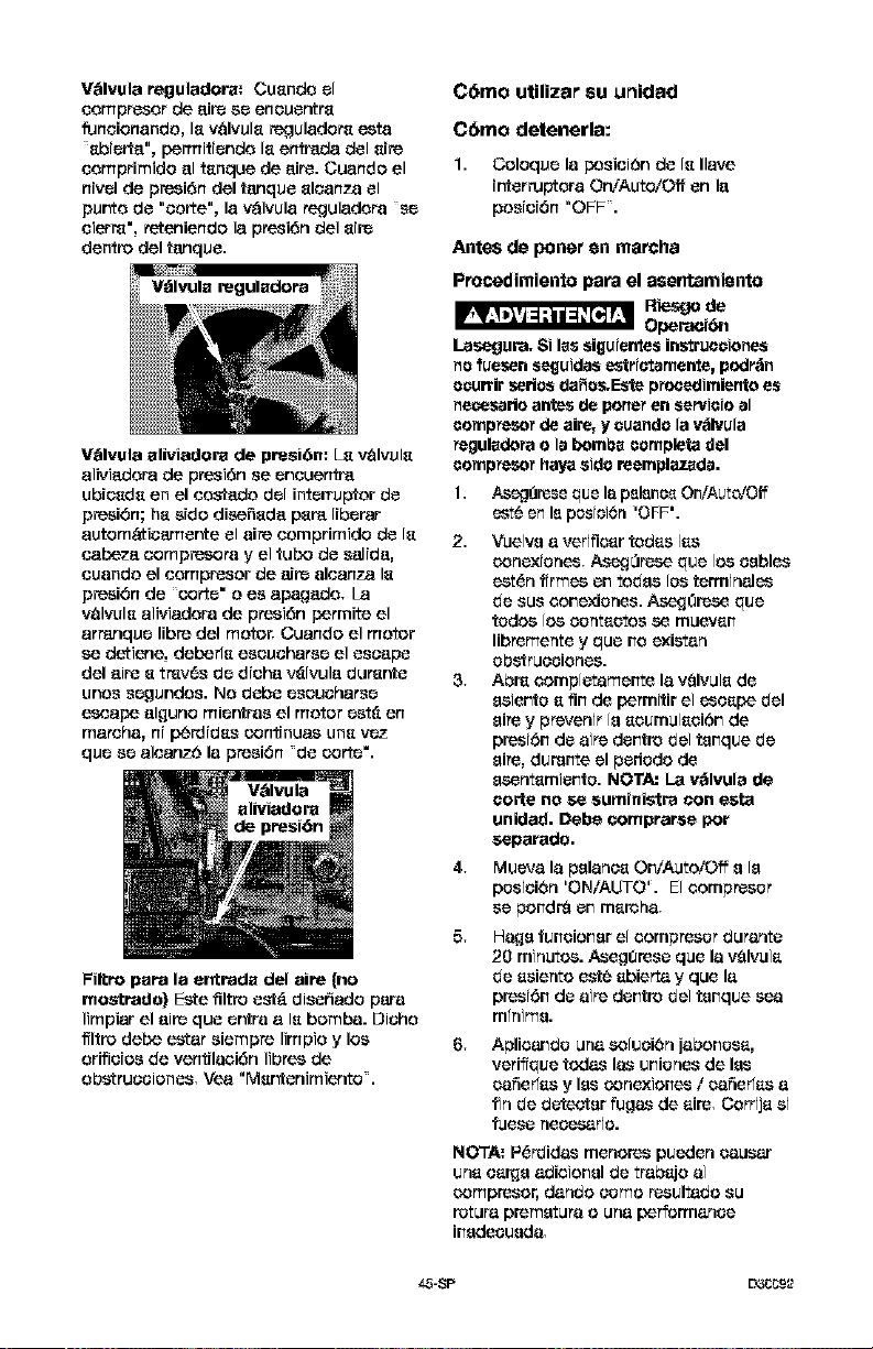
V_lvula reguladora: Cuando el
eompresor de air_ ac eneuentra
funeionando, la v_lvula reguladora eeta
abierta", permitiende la entrada del airs
eomprimido el tanque de airs. Cuando el
nivel de presi6n del tanque aleanza el
pur_o de "aorta", la v_lvula reguladora se
sierra', reteniendo la presi6n del airs
dentro del tanque.
V_lvula aliviadora de preai6n: L_ v_lvula
aliviadera de preai6n se eneuentm
ubieada en el eostado del interru_or de
presi6n; ha side diea_ada pare liberar
autom&tieamer, te el aire eomprimido de la
eabeza ¢,ompreaora y el tub<) de salida,
euando el eompresor de airs aleanza la
presi6n de oortc" o es apagado, La
valvula alMadora de presi6n permits el
arranquc libra del motor, Cuando el motor
ea detiene, deberla eaeuehares el escape
del airs a tmv6s de dieha v_lvula durar_e
unos scgundos. NO debe eseueharsc
escape al_uno micr'_raa el motor est_ en
mareha, ni perdidas continues una vcz
quc ea aleanzb la presi6n de oortc'.
FiRro pars la entrada del aim (no
rnostrado) Eete filtro eat& dissuade pare
Iimpiar el airs qua cr_ra a la bombs. Dieho
ffltro debe ester siempre Iimpio y lea
orifieiea de ventilaei6n Iibrea de
obetrueeiones, V_ "r'Aar,tenimiento.
C6mo utilizar su unidad
C6mo detenerla:
1. Coloquc la pesiei6n de la Ilave
{r_errupteraOn/Auto/Off en la
peaiei6n "OFF.
Antes de poner en marcha
Procedimiento para el asentamiento
R_v_o de
Operacibn
Lasegura, 8i les siguiemes instrueciones
no fueesn seguides estrictsrnen_e, peslr_n
ocuftir series da_es.Eete procedimiento es
neceesrio antes de porter en servicio sl
compte_r de awe, y cuande la v_flvula
Peguladotao Is bombs cernpleta del
compresor ha,}raaide reemplazads.
1, AesgOreesqua la pslsnes On/Aut_zOff
eat6 en Is postsi6n "OFF'.
2,
3,
4,
5,
6,
Vea[ve a verifiear redes ]as
conexter|es, Aseg0rese qua ]ea cables
est_n ftrmes en todes [ca tenninales
de ses eonexiones. AsegOresc qua
tedea [ea eantactea sc muevan
libremente y qua no existan
obstrueeiones.
Abn_ eomp[etamente la vQIvu]a de
esiente a fin de permttir ei escape del
ape y prevenir [a aesmulacibn de
prest6n de airs dentro de] tanque de
ape, durscte el pededo de
ascntamiente. NOTA: La v_lvula de
torte no se auminiatr_ con esta
unidad. Debe comprarae per
separado.
Mueva la pelanea On/Auto/Off e [e
peateibn 'ON/AUTO'. E[ compreser
se pondr_ en maroha,
Ha_a funcionar e[ compreser _urante
20 minutea. A.seg_rese qua la vQIvula
de asiento este abierta y qua la
prest6n de airs dentro dei tanque sea
mlnima.
Aplicande una ea[ueiOn jaboneaa,
veriftque redes las uniones de les
_4_fiedas y les eanexiones / _4_fiedas a
fin de detecter fugas de aim, Corrija si
fuese neeasario.
NO_i'A:P_rdides menores pueden _*4_esar
una ea_e a0ieionel de trabajo a]
eampreear, dando come resulta0o su
rotura premature o urea performance
inedeaueda,
4.5-8P L_CCg_2
7. VerJfique la existenoJs_ de vibraoJbn
exo_sivs. Resjuste o acufie el pie del
compresor, s1_11ofgera n_sarJo.
8.
Luego de 20 minutos, oJ_rre 18_
vSIvul8 de asiento. El aire _oJbJdo
elevar8 la pr_siOn hasta el punto de
pr_siOn de Corte', y ello hsr_
detener _1m_or.
El _,ompresor estar_ ahom li_to pare ser
us_do.
Antes de cada puesta en marcha
11 Co[oque el rnterruptorOn/A_toiOff en la
posici6n "OFF" y oierm el _ulador de
2. Cierm la v_lvulade asier_o,
Conecte la mangugra y accesorios.
NGrrA: Cuando se utilben aooesorios
especific_dos p_ menos de 175
PSI debgr_ Jnstalatse un i_gul_dor,
Riesgo de
Explosi6n.
Demasiada presi6n de aire podt_fser la
causa de riesgo de explosi6n. Verifique los
¥alores de m&xima presi6n dados pot el
fabricante de las herramientas neum_iticas y
los accesorios. La presi6n de salida del
regulador jam_s debe exceder los valores
de m&xima presi6n especificados.
C6mo poner en marcha
|,
Mueva la palanc_ On/A_toiOff a la
posiot6n "AUTO" y deje que s_
i_c,remente [a pres[6_ del tanque. El
motorse detendKauna vez alcanz_doel
W.lo_de presi6n "de.¢o_" de[ mnque.
2. Cuando la preslOn dgl t_nque
_lcanza el valor de "ptesi6n de oortg"
sg abr_ la v_lvula de 8.,'_igi'ItO,
IMPORTANTE: AI utilizsr un r_ulador y
otros aoo_sorios, refi_mse alas
instruooiones del f_brioante.
--)_,Y,_2 44_-8P
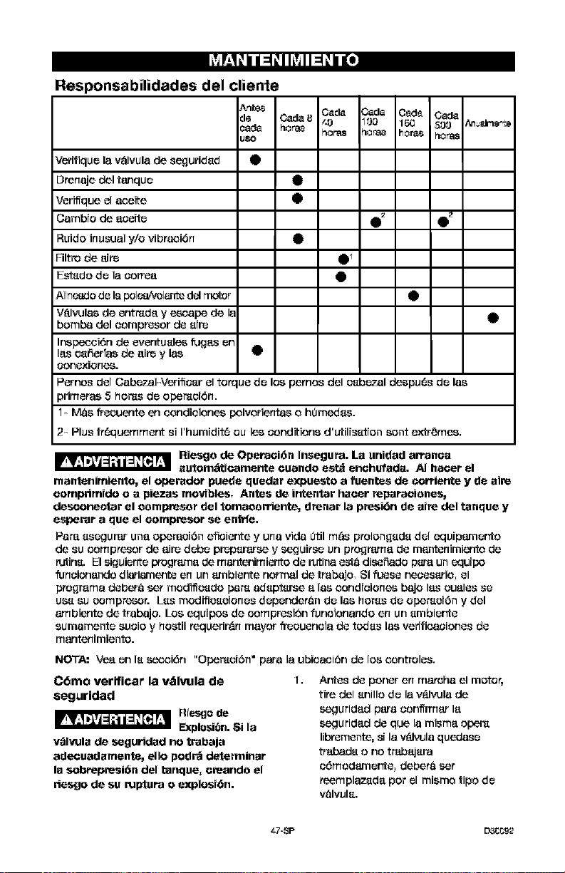
YAWl_l 1:1_1IkVAII:l_ l I[I
Responsabilidades del cliente
Ar'rb_ Cads Cads C_d_ Cads
de Cede8 _O 100 16(; 500 An,_Jne,_
c_d_ r'lOr_,8 r'lOras r'lOr_3 h or'_ r'lOras
usa
Vorifique la v_lvula de se_3uridsd •
Drenaje del tanque •
Vorifique ol aseite •
Cambio de a_oite 0 2 411)_
Ruido inusual y/o vibraoi6n •
Filtro de _ire 411)_
Estsda de la oarrea •
A11n_adode Ispo1_&_1_1_ d_lmotor
V_lvulas de ontmda y esoape de le •
bombs del oampresar do sire
Inspecoi6n de ovontuslos fugas on
lasosSorTas de ait_ y laa
oanoxionos.
Pornse dol CabezaFVerifiosr ol tonquo de los pernos del osbezal despu6s de las
primoras 5 hams de opemoiOn.
1- MaS freouento en sendioiones polvorientas o h0medss.
2- Plus fr6quemmont s1I'humidit6 ou los senditions d'utilisstion sent extremes.
Riesga de Opareoi6n Insegura. La unidad arranoa
automt;iticamante cuando astd anohufada. AI haoer el
mantenimiento, el operador pueda qoedsr expoesto a foentes de corriertte y de sire
oomprimido o a plazas movibles. Antes de intentar hacer reparaoianes,
desconec_ar el oampresar del tomaoarriante, drenar la presi_n de airs del tsnque y
asperar a qua el oompresor se enfrfo.
Pare ss_gurar una op_raci6n ofioior_e y una vida 0til m_ prolongsds del _luipamer_a
de su sempresor de air_ debe pr_psrars_ y seguirse un programs do mant_nimi_to do
tutins. El siguiente progr'ama de mantenimionto do rutina osta di_fiado pars un _quipD
funoionanda diariamerxi_ en un ambior_e normal de trabajo, Si fuoso neaosario, ol
progmma debar8 set modiflosdo pare adsptsrse alas oondioionos bajo lasoualos so
use su compresor. Lss modifiosoiones dependeran de las hams de opemoi6n y del
ambiento de trabajo. Los equipse de sempresi6n funoionando en un smbier'_o
sumamente suoJo y hostil requorir_n mayor freouonoia do tc_:iss las vodfioaoianos do
mantenimiento.
NOT,e,= Vea on Is se_mi6n "Opemoi6n" pars la ubioaoi6n do los oontrolos.
C6mo verificar la vdlvula de
seguridad
Riasgo do
Explosibn. 8i la
v_lvula de seguridad no trabaja
adecuadsmente, ella podr_ detenninar
la sobrepresibn del tanque, ereanda el
riesgo de so rul_ura o axplosi_n.
1.
Ar_os do panor en maroha el motor,
tire del snilla do la v&lvula de
seguridad para oanfffmar la
seguridad do que la misma apem
libremonte, si la v_lvula quedaso
trabads ana trabajsra
o6madamor_o, debera set
reemplazsda per el mismo tipa do
valvuls.
L7-SP D3_2
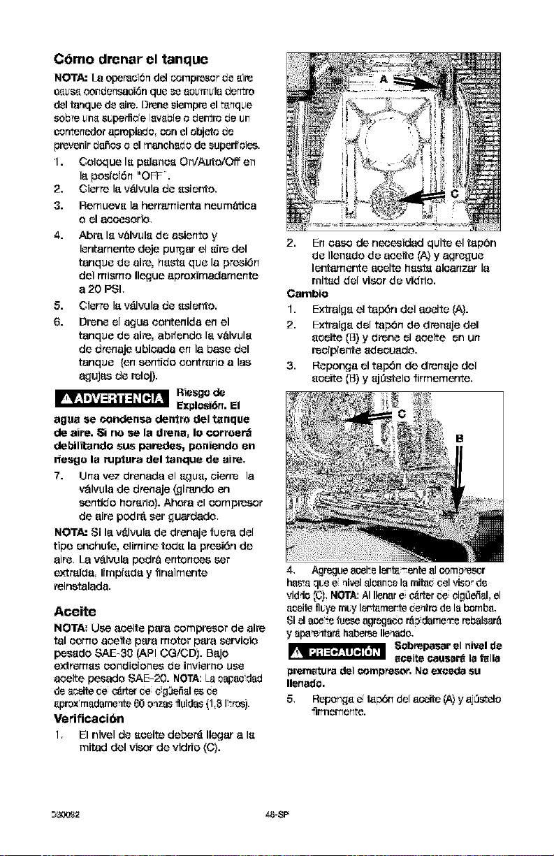
C6mo drenar el tanque
NOTA:/a ope_oi6_ del _mp_sor de _i_
o_us_ conde_s44ei6nque _e {ioumul{ide_tro
delta_quede Bite,DreneWempre elt_nque
sob_eun_supe_de ]Bw.b[_o dei1trod_ Ui1
oomtenedorapropiado,sen elobjetode
prevenirda_oso elrllBnohBdode _uperf{oies.
I. Coloque I_p_lano_ On/Auto/Offen
I_posioi6n"OFF.
2. Cierr_ I_ v_dvula de _si_r_o.
3. Remuev8 la herramier_a neumetica
o _1 accesorio,
Abm I_ v_lvul_ de asiento y
lentamente deje purer el _ir_ del
tanque de aim, h_st_ que la presi6n
del mismo Ilegue aptoximadamente
a 20 PSI,
5. Cierr_ I_ v_lvula de _sier_o.
6. Drone el ague eontenida en el
tanque de aire, abfiendo I_ velvul_
de dtenaje ubicada en la base del
tanque (en sentido eontr_rio alas
aguja_ de relo_.
Riesge de
ExplosiOn. El
ague se condense dentro del tanque
de aire. _ no se la drena, Io corroerd
debilitando sue paredes, poniendo en
riesgo la rupture del tanque de aim,
7. Una vez dr_nada el _lgus, eierr_ la
v_lvula de drenaje (girando en
sentido hot,rio). Ahera el c_mpre_r
de eire petit& ser _uardade,
NOTA: Si le v_lvule de drenaje fuem del
tipe enehufe, elimine tod_ la ptesi6n de
Bite, L_ V&l'*_Jlapodt_ entonses ser
e&'t_lde, limpi_de y finalmente
reinstalada.
Aceite
NOTA: Use aeeite pare eompresor de aire
tel come aeeite pare motor pare servieio
pesedo SAE_3O (API CG/CD}. Bejo
extremes eondieiones de invierno use
aseite pesado SAE-20. NOTA: La_apaodad
d_ a_eitece e_rter cee g3efial_s ce
apmx madame_te80 o_zasfluidas {1,81-.roe).
VerificatiOn
1, El nivel de _leeite de_r_ Ileg_r a I_1
mit_d del viser de vidrio (C).
2. En ease de necesidad quite el tep6n
de Ilen_do de aeeite (A} y agr_gue
ler_amer_e aoeite h_st_ alcanzar la
mired del visor de vidrio.
Cambio
1. Extraig_ el tap_n del eseite (A).
2. Extraig_ del tap6n de dren_je del
_seite (B) y drene el aceite en un
reeipiente 8deeuedo.
3. Reponge el tap6n de dren_je del
8eeite (B) y 8j0_elo firmemente.
4, Agr_gue eoeite I_-t_ente eloom_'esor
h&_.aq_e e qivel al_noe la mitac_el visorde
vidde (C), NOTA:AI Ilenere e4_rterce eig0efial,el
aeeitefl_yem_y I_t_me_te centrede la bomb&
8i el aeete fuese egr_aee r_ dame_-erebalsar_
y apa'e_tar_ haberseIleqade,
Sebrepasar el nivel de
eceite eausa_ lafalla
premature del eompreser, No exeeda eu
Ilenade.
5, Repong_ el t_p_ de[ _oeite (A} y _jLlstelo
fitrner_ente.
--)_,Y,732 44J-SP
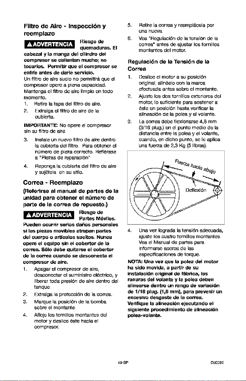
Filtro de AJre - Inspecci6n y
reemplazo
Riesgo de
quemaduras. El
cabezal y la mangu det oilindro del
compresar se oalJentan muohol no
taoarlos. Permitir qua el oampresor se
entrfe antes do darle servioia.
Un flltro de aire sueio no permitird qua el
eompresor opera a plena eapacidad.
Mantenga el filtre de aire limpie an todo
memento.
1. Retire la tape del filtro de aire.
2. Extraiga el filtre de aire de la
eubierta.
IMPORTANTE: NOopera el _ompre_,or
srn su flltre de aire,
3. Instals un nuevo filtro de aire dentro
la oubierta del iiltre, Para obtener el
n0mero de pieza eorrecto, Refferase
a "Piezas de repamoibn"
4. Reponga la oubrerta del filtro de aire
y suj_tela on eu sitio.
Correa - Reemplazo
_eferirse al manual de partes de la
unidad para obtener el n_mero de
porte de la correa de repuesto.)
Riesgo do
Partes M6vilas.
Pueden oeurrir series daces pePsonales
si les piezas movibles atrapan partes
det euerpo o arUeulos euelto_, Nunoa
opera el equipo sin el oobertor do la
oorrea. 861a debe quitarse el eabertor
de la correa ouando so desconacta el
oompresor de aire.
1. Apagar el eompresor de aire,
desooneotar el suminis_ro el_ctri_o, y
liberar toda presi6n de aire dentre del
tanque,
2. E,'<traiga la prote_oi6n de la correa.
3. Marque la poeici6n de la bomba
sabre el montante,
4. Atloje los tomilloe montantes del
motor y desliee este haoia el
eompresor.
5,
6.
Retire la eorrea y reempl_eela per
Ufla flUeVa,
Vea "Regulaoi6n de la tensi6n de la
eorrea" antes de ajustar los families
montantes del motor.
Regulaci6n de la Tensi6n de la
Correa
1. Desli_'_ el motor a su posioi6n
original; alin{_elo con la marea
efeetuada antes sabre el mor'_ante.
2. Ajuste los dos tornillos exteriores del
motor, Io sutieiente para soetaner a
{_ste an posioi6n ha_a verlfioar la
alineaci6n de la polea y el volante.
3. La eorrea debe tlexionarse 4,3 mm
(3/16 plug.) an el punto media de la
distanoia entre la polea y el volante,
euando, en dioho punto, se Is aplioa
una fuerza de 2,3 Kg (5 libras),
¢_r'ze heataaba.io
4. Una vez Iograda la tansi_Snadecuada,
ajuete los ouetre tomillos montantes,
Yea el Manual de partes pare
informarse aoerea de las
especificaeiones de torque.
NOTA: Una vez qua la polea del motor
he side movida, a partir do su
inslalaei6n original do I_brica, los
ranuras del volante y la polea deben
alinearse dentro un range do variaei6n
do 1/16 plug. {1,6 ram), para prevenff un
excesivo dasgaste de la earrea.
Verifique la alineaci6n ejeeutando el
siguiente procedimiento do alineaeibn
polea=volante.
• 9-SP EY3_g2
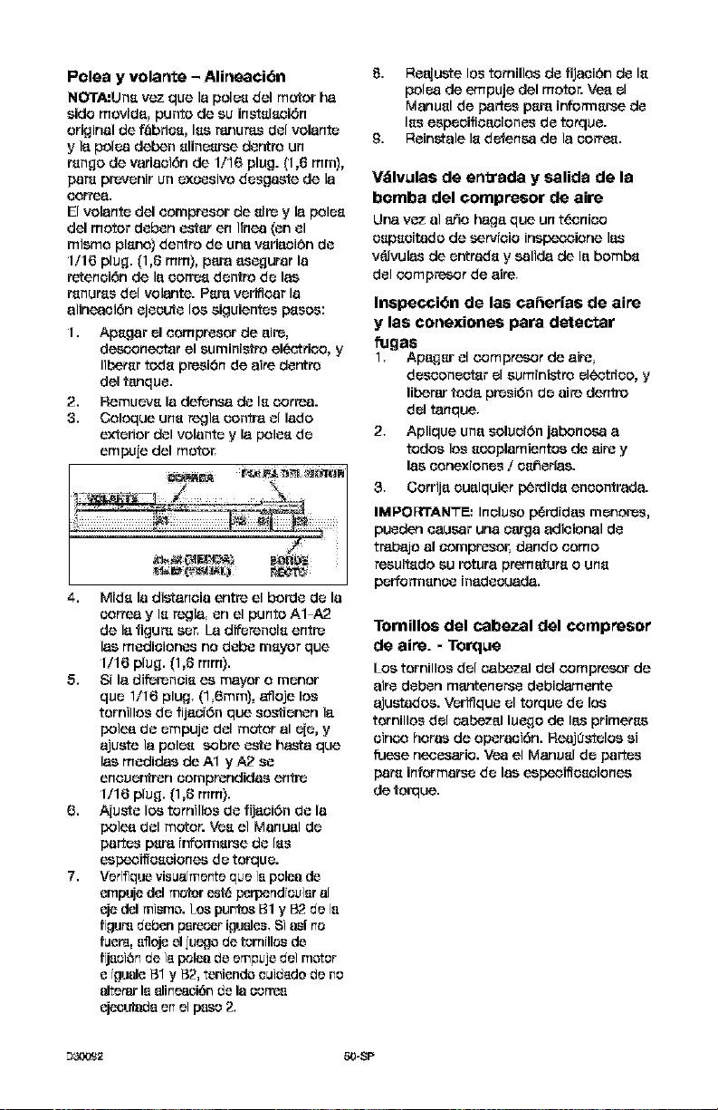
Poles y volarlte - Alirleaci6n
NOrrA:Un_ voz que lapole_del motor ha
sidemov;da, punto do su inst_l_oi6n
original de f_brios, Iss ranuras dol volante
y la polea deben slinesrse dentre un
tsngo do vatiaci6n de 1/16 plug. (1,8 ram),
pare prevenir un exeesivo dosgaste de la
eorr_.
El volante del eompresor de s;re y la polos
del motor deben estar en IInea {on el
mismo plsno} dentro do una vsriaci6n do
1/16 plug. (1,8 ram), para asegurat la
retenoi6n de la eon'_sdentro de las
rsnurss del volante. Psra verifioar la
alineaei6n ejeeute los siguientos psses:
1. Apsgar el eompresor de aire,
de_x)neotar el sumini_ro el_otticx), y
Iibersr teals presibn de aire dentre
del tanqse.
2. Remuevs la defensa do Is c,orrea.
3. Coloque uns regla centre el lade
exterior del volante y la polos de
empuie del motor,
4. Mids la distanoia entre el bonde de la
correa y Is r_la, on el punto A1 -A2
de la figure set, La diferene;s entre
las medieiones no debe msyor que
1/16 plug. (1,8 ram).
5. S; la difereneis es mayor o menor
qse 1/16 plug. (1,6mm), afloje los
tornillos do fijacf6n que sos_fenen la
pole_ do empuje del motor al eje, y
ajuste la polos sobre este basts que
las medidas de A1 y A2 so
enouer'_ren comprendidas entre
1/16 plug. (1,8 ram).
6. Aiuste los tornillos do fijaci6n do la
pole_ del motor. Yes el Manual do
partos psr_ ir#orrnsrse do Iss
espeoiffseciones do torque.
7. Ve_if]quevisas[monte qc+eiapoles do
empuje del motor ast_,perpendicular s[
eje del mismo. Los pastes B1 y 132de la
ftgura deben parecer igualas.8i as[ no
fasr_, afloje el iuegodo tontllos do
ftjaoiSn do 1_.p_l_ do empuje del motor
e tousle B1 y B2, teniendo cuid_do de no
alterar la alinosci6n do Iscortes
eje0uta_a en ei paso 2.
8. Reajuste los torn,los de fijaei6n de Is
poles de empuje del motor. Ve_ el
Manusl de partos psr_ ;r#orrnsrse de
Iss especificacionos do torque.
9. Reinstale Is defense de la cortes.
Vdlvulas de en_rada y salida de la
bomba del compresor de aire
Una vez al ar3o hags que un t_cnioo
sepseitado de servioio inspe_ione las
v_lvulas de eefrads y salida de la bombs
del c_ompresor de sire.
Inspecci6n de las ca6erias de aim
y las conexiones para detectar
_Jgas
1, Apagsr el c,ompresor de aire.
doseoneefsr el sum;nistre eleotrfeo, y
liberar toda presi6n do sire dentre
del tanque.
2. Aplique una seluo;6n jabonose a
todos los sooplamientos de sire y
las conexionos / seher|as.
3, Corrija eualquier perdids eneontrada.
IMPORTANTE_ Ineluso p6rdidas menores,
pueden causer una earga adieional do
tr_bajo al eompresor, dando come
resultsdo su retura premafurs o uns
perforrnsnoe {nadeeuada.
Torn,los del cabezal del compresor
de aim. * Torque
LOStornillos del c,_bezal del c_mpresor de
sire deben mantenerse debidamente
ajustados. Veriflque el torqse do los
tomillos del c,_bezal luego de las primerss
einoo betas de operaei6n. ReajOstelos s1
fuese necesario. Yea el Manusl do partos
pars informarse do las espeoiffseoiones
de torque.
--)_2 50-SP
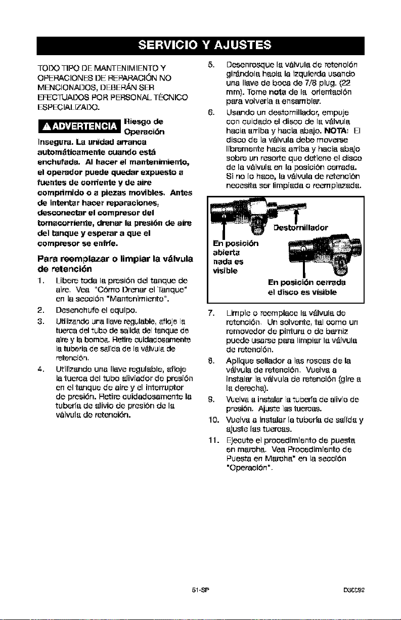
TODO TIPO DE MANTENIMIENTO Y
OPEP-ACIONES DE REPAP,AOION NO
MENCIONADOS, DEBEI_ SER
EFEC PJADeS PeR PERSONAL T_CNICO
ESPEC[ALIZADO.
Insegura. La unidad arl-anca
automdtiesmente euando est_
enohufada. AI heoer el mentenimiente,
el operador puede querier expuesto s
fueates de oorrlente y de aire
oomprimido o s piezas movlbles, Antes
de intentar hater reparaciones,
desconec_ar el compresor del
temscorrier_e, droner la presi6n de eire
del tenque y esperar a que el
oompresor se enfrfe.
Pars reemplazar o limpiar la vdlvula
de retenci6n
1. Libere toda le presidn del tanque de
sire, Ve_ "Crime Droner el Tanque"
en la scocidn "Mantenimier_o".
2. Desenchufe el cquipo.
3. Utiliz_ndo urealisvc regulable,efloie Is
tuercs del tube de ssiide del tsnqus de
sire y Is bomb& Retire cuidadocamcnte
1stuberls de s_lids de Is vAIvu[_de
retcncidn,
4. Utilizsndo una Ileve regulsblc, sflejc
la tuerea del tube slivJador de presJ6n
en el tanqca de sire y el interrupter
de presidn. Retire cuidadocamente la
tubcde de slivio de presidn de Is
valvuls de retenoidn.
5,
Desenresque Is valvule de retenci6n
gir_ndole hecis la izquie_a ucando
una Ileve de boca de 7/8 plug. (22
ram). Tome nots de le oricntaoidn
pars volverla e ensam bier.
Usando un dcatomillador, empujc
con ouidedo el dis¢_ de Is v_lvule
hacie srriba y hacia abejo. NOTA: El
disco do lav&l'_Jla debe moverse
libremcnte hecis arriba y hacie sbaio
sobre un recorte que detiene el disco
de la valvuls en la posicidn corrads.
Si no Io hsca, la v&l_Jla de retencidn
necesite scr Iimpisde o reemplazsds.
7. Limpie o reemplace Isv_lvule de
retcnci6n, Un solvcr_e, tel come un
rernovedor de pinture o de barniz
puede ucarse pars lirnpisr le v_lvule
de retenci6n.
8. Apliqca collador a I_ roscas de la
v_lvula de retcncidn, Vcalvs a
instalar le v_lvula de retcncidn (gire e
Is dereohs).
9. V_e[vs s instalar is tuberfs de a[ivrc de
presi6n. Ajuste ias tuereas.
10. Vcalvs a instslar la tubcrfe de sslids y
sjust8 Iss tusress.
11. Ejecute el procodimicnte de pcas_e
on msrehe. Vee Proccdimicnte de
Pucata en Msrehe" en la secci6n
"Operaoidn",
51-$P EY3_92

Motor
E_e motor tiene un prot_otor manual do
sobPecan]e tetrnrea. Sr el motor So
sobPecalienta per eualquier motive, el
protector de sobr_eelga apage el motor,
Debe permitirse que el motor er#rle entes
de volverlo a arranear do la eiguiente
farina:
1. Mover la palanquita do On/Auto/Off e
la posiel6n do Off.
2. Permitir que el motet se en_t|e.
3. Pr_sioner el bot6n tojo do
I_elnielalizael6n (Reset) que es_ en el
motor,
4. Pore ercarlcer el motor mover la
palanquita do On/Auto/Off a la
poeioiOn de On/Auto,
NOTA= Si el protector de sobr_earga
epaga el motor ¢,on mueha ftecuenele,
verif_que si hay alg0n pesible
probleme de voltaje. Tambien se puede
sespsehar de
bajo voltaje cuando:
1.
2,
El motor no aleanza toda su poteneia
o veloeidad.
LOS fu_ible_ _e queman euando Se
ercanoe el motor; le_ luee_ _e
etenOan y elguen atenuad_ euando
el motor es 8_terleedo y eet_ erl
funeionsmier_o.
Servicio Adicional
NO se tesomienda desarmat ni derle
servieio e e_te eompr_sor do eir_ m_%all_
do Io ttatado en este manual. 8i se
r_quier_ do servicies edieloneles,
eonteeterse con el Cantro de SerJieles de
Oer_tTa Aetor_7_do m_ eeroeno.
Aries do guerdar su compr_ser de air_,
a_0rese de hater Io siguier_e:
Hevise la seeel6n "Mantenimier, to"
de las p&.qinas precedentee y ejesute
el mar'_enimianto ptogramado do
acuerdo a le neeesided,
2. Coloque la pelanea On/AUto/Off en le
poeici0n "OFF'.
3. Cierre la v_lvulade B._ier_o
4. Extte[ga la herr_m[enta neum#_tiea o
el _3oesorio.
5.
Abra la v_lvula do asiento y
lantamante deje pulgar el aJredel
tanque do eire, heste que le ptesi6n
del mismo Ilegue aptoximadamente a
20 PSI.
6. Drene el ague del tanque do aire
abr_ando le valvule de dreneje
ubiesde en el fondo del tanque.
_ Riesgo do
Explesi6n. El ague
se condense dentro del tanque de aim.
Si no se drena, ella eorroerd debili_ando
las paredes del tanque de aire,
originando un riesgo de rupture de sue
paredes.
7. Una vez que el ague haya side
dr_nada, cierre la v_lvula do dr_naje,
NOTA= Si le vSIvule do dreneje estuviese
enehufada, Iibete rode la presi6n de air_,
La v&lvula podr8 set extralda, limpiada y
luego teinetalada.
8. Proteje la manguem del aire do
dar3es (teles come set pisetesde o
esminer per eneima}.
_msDene el _mpn_ot de eire an un _itio
limpio y sese.
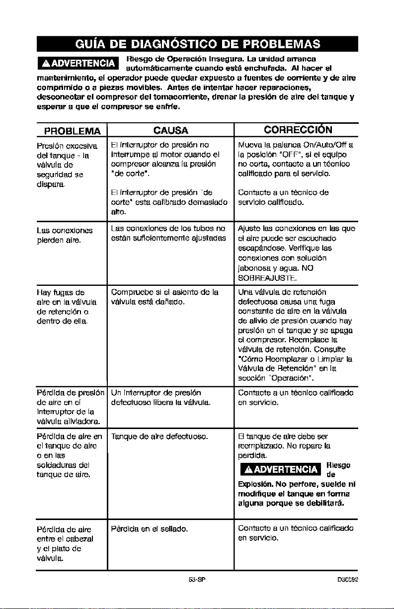
Riesgo de Operaci6n Insegura. La unidad arranca
autam_ticamente cuando est_ enchufada. AI hater el
mantenimiento, el operador puede quedar expuesta a fuentes de corriente y de aim
comprtmido o a plazas movibles, Antes de irrtentar hacer feparaciones,
desconec_ar el compresor del tomacarriente, drenar la pfesi_n de aim del tanque y
esperar a qua el compresor se enfrfa.
PROBLEMA
Pr_r6n exc_siva
del tanque - la
v_lvula de
segur_dad se
dispa_,
L_Is_rlexiones
pienden aire.
Hay fu_as de
aite _n la v_lvula
de refenci6n o
dentro de ella,
CAUSA CORRECCION
El ir_erruptor de presi6n no
interrumpe al motor ouando el
oomptesor aloanza la presi6n
"de oodo'.
El ir_erruptor de ptesi6n de
ootte" esta oalibmdo demaoiado
alto,
L_s oonoxiones de los tubes no
es_n oufioientemente aju_edes
Compruebe si el aoiento de la
v8lvula est_ dafiado.
P6rdida de presiOn Un interrupter de ptesi6n
de aire on el defeotuoso libera la v_lvula.
interrupter de la
v_lvula aliviadora.
P6rdida de aire on Tanque de aire defeotuoso.
el tanque de aite
o on la_
soldadur_s del
tanque de aire.
Mueva la p_lanoaOn/Auto/Off a
la posioi6n "OFF", si el equipo
no ootta, oontaote a un tecnioo
oalifioado para el setvioio.
Contacte a un t_tmioo de
servioio oalilt oad o.
Ajuste las oonoxiones en las que
el aire puede set ascuohado
escap_ndose, Verffiquo las
oonoxiones oon _oluoi6n
[abonooa y ague. NO
SOBHEAJUSTE.
Una v_lvula de retonoi6n
d_eotuosa oausa una fuga
oonstar_e de aire en la v__lvula
do alivio de presi6n ouando hay
)resi6n on el tanque y so apaga
el oompresor. Reemplaoe la
v_lvula do retend6n. Consulte
"C6mo Reemplazar o Limpiar la
V&lvula de Retenoi6n" on la
soooi6n Oporaoi6n".
Contaoto a un teonioo oalifioado
on sorvioio.
El t_nquo de aim dobe set
ree_plazado. No repare la
)o_ida,
Riesgo
de
Explosi6n. No peM'are, suelde ni
madifique el tanque an farina
algurta porque sa dabilita_.
Perdida do aire P{_ida on el oollado. Contaoto a un teonioo oalifioado
entre el oabozal on sorvioio.
y el plato de
valvula.
53-SP L_CCg_2
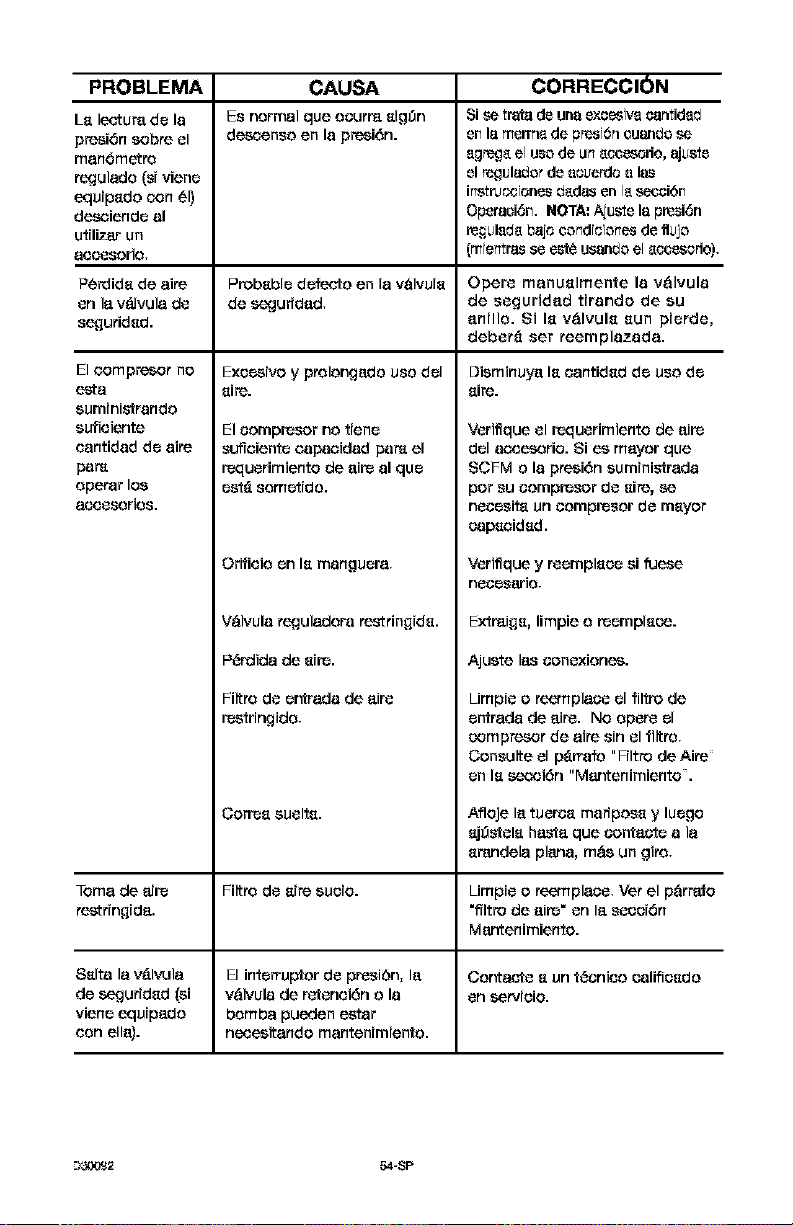
PROBLEMA CORRECCION
L_ lectur_ de la
presi6n sobre el
man6metro
regulado (si viene
equip_do con _1)
desoiende al
utmzar un
aooesorio.
Perdide de aire
en la v_lvula de
se¢]urided.
Eloompresor no
esta
euministrando
eufieiente
eantidad de aire
pam
operar los
aeeesorios,
CAUSA
Esnormal qua oeurraelg0n
deso_nso on la presi6n.
Probable defecfo en la valvule
de segurfdad.
Exeosivo y prolongado usa del
sire.
El oompresor no tiene
suffoiente oapaoidad pam el
requerimiento de aire al qua
ost_ som_tldo.
Orifieio en Is manguera.
V&lvula reguladora restringide.
P{,'rdida de eire.
Filtro de er',trada de air_
restringido,
Coffee euelte.
Si s_ trata de una excesiva cantidad
en lamenne de presr(_neuando s_
egreg_,e[use de an _.ce_odo, ajus_e
el regula_o_ de eel.+en:lee 18
instrl.+o0tenesdedas on [e_ci6n
Operaei6n. NOTA: Aju_e la presi6n
regL+ledebaje eondteiones de fllJjo
(mtentrasso este usando e[ eceesorio).
Opera manuelmente la v&lvula
de eeguridad tirando de eu
anillo. 8i Is v&lvule sun pierde,
deber_ ear reemplazada.
Dieminuya Is t.',_ntided de ueo de
sire.
Veriffque el requerimiento de aire
del aocesorio. Si ee mayor qua
SCFM o la presi6n euminis_rada
per eu eompreeor de sire, se
neeeeite un eompreeor de meyer
capeoided.
Veriffque y reempleee si fuese
neoeeario.
Extraige, limpie o reempleoe.
Ajuete IaS eonexiones.
Limpie o reemplaee el filtro de
entrada de aire. No opera el
oompresor de aire sin el filtro.
Coneulte el p_rrafo "Filtro de Aire
en Is seoci6n "Mar, tenimiento .
Afloje la tuerce marfpoee y luego
ej_ele ha_,#aqua contacts a la
erandela plan& m&s un giro.
Toma de aire Filtro de sire eueio. Limpie o reemplaee. Ver el p&rrafo
restringida. "filtro de aire" en la eeeei6n
Mantenimiento.
Selta la v&l_Jla El interrupter de preei#n, la Contacfe e un t{,'enieo oalifieedo
de segurided (el v&lvula de retenei6n o la en servieio.
viene equipado bomba pueden eetar
con ella), neceeitando mantenimiento.
--)_2 54-$P
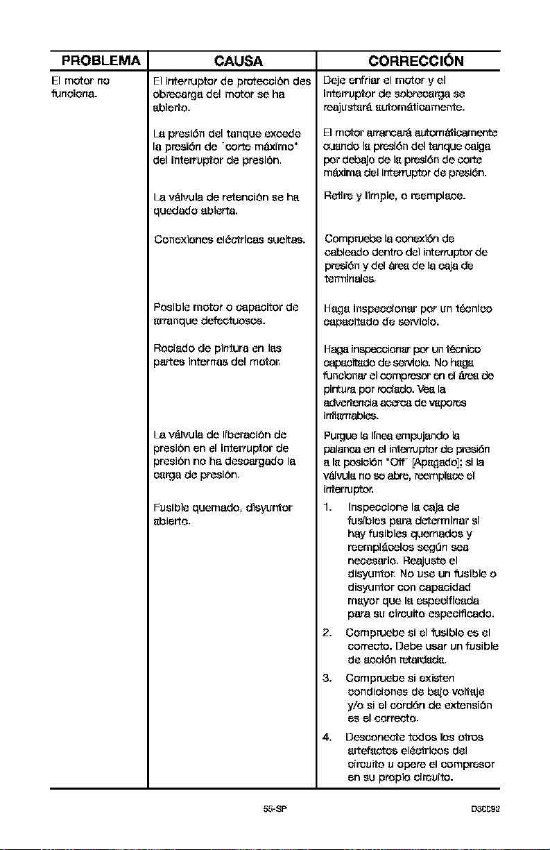
PROBLEMA
Elmotor no
fuMCIoMa.
CAUSA CORRECCION
Elinterruptorde prot_oiOn dos
obr_arga del motor se ha
ebierto.
L_ pr_si6ndeltanque excede
lapresi6nde torte mQxime"
del interrupter do presiOn,
La v&lvula de retenoibn so ha
quedado abierta.
Conexionee el_otrie_ suelt_.
Posible motor o capacitor do
erranque defe_fuosos.
Rooiedo de pintura on la_
_arteeinternes del m_or.
v_Jvula de IiberaeiOn do
_r_sit_n On el interrupter do
_resibn no ha deseargado la
_e_a do presiOn,
Fusible quemado, dieyur_or
ebierto,
Deje er#riar el motor y el
interrupter do sobreoelga so
reaju_ter_ eutom_ticamente.
El motor artar_c_r_ autcm_icarner_
euendo le pn_sJ6ndel tanque caiga
per d_bajode le pn_sJ6nde colt_
m_Jma del int_'tuptor do pr_si6n.
R_ire y Iimpie, o reempleee.
Oompruebe la ecnexi6n de
c_ble_do dentn_ del internJptor de
pn_6n y del _ de la caja de
_nmin_es,
Ha,qe inspeeeionar per un t_cnieo
eapaeitedo de servieio.
Haga inspeocionar per un tecnic_
cap_cil_do de servicio. No hage
funcionat el compR_c_ en el _ de
pinfur_ per tocJedo. _ la
adv_eneia _ do v_pore_
inflsrn_ol_.
Pu_ue la I[nea empujando la
palanc_l on el interrupter de pl_si6n
a le posieken "Off [Ap_qado]; si la
v_ilwJle no se abre, reemplece el
interrupter.
1. Insp_oione le eaja do
fusibles pera determiner s[
hay fusibles quemados y
reempl_celoe segOn
necesario, Reajuete el
disyuntor, No use un fusible o
disyuntor con eapeeidad
meyer que la espeeifieada
pare su eireuito espeeificado.
2. Compruebe si el fusible ee el
eorrecto. Debe user un fusible
do eooi6n reta_lede,
3. Compruebe si existen
eondieiones do bejo voltaje
y/o siel cord6n do extensi6n
es el correcto,
4. Desconecte redes los otroe
ertefeetoe el{_otricos del
circuito u opere el compresor
on su propio circuito.
55-8P L_CCg_2
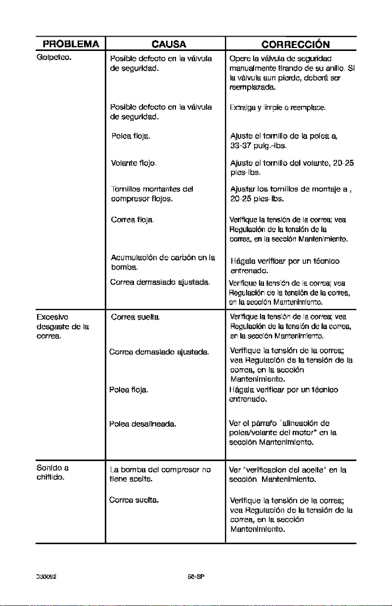
PROBLEMA
Golpeteo.
CAUSA
PosibledefeGtoen la v_Jvula
Exeesivo
deegaste de le
corr..
de sequrided.
Posible def_Gto en la v&lvula
de sequrided.
Son{do a
ehiflido.
Polea floje.
Volante flojo,
Tomillos montantes del
eompresor flojos.
CoEea floja,
AcumuleeiOn de earbOn en le
bomba,
Correa demasiado ejustada,
Correa suelta,
Cortes demasiado ajustada.
Poles floja.
Poles desalineada.
I_ bombf! del _ompresor no
tiene _eite.
Cortes suelta.
CORRECCI_N
Opere la v{_vula de seguddad
menualmente tirando de su anillo, 8i
le valvule eun pieEle, deben_ set
reemplaz_d8.
Extr_igay [impie o reemplace.
Ajuste el tomillo de la polee a,
33-37 pulg=lbs.
Ajuste el tomillo del velar,re, 20-25
pies-lbs.
Ajuster los tornillos de monteje a,
20-25 pies-lbs.
Verffique Istension de [ecorm.a;vea
RegulaeiOnde le tension de la
coffee, en [s _ciOn Mantentmiento.
H___elaverifiear por un tOenieo
er,trenado.
Verffique Istension de [ecorm.a;yea
RegulaciOnde ]etension de la co,tea,
e_ la se_rOr_ Me_tenimre_te.
Verifique Is teneiOnde [ecorm.a; vee
Regulaci6n de latenstOn de Is co,tea,
en la se_ro_ Mentenimie_te.
Verifique la tensiOn de laoorree;
yea ReguleeiOn de la tension de la
eorf_fl, en le s_'3iOn
Mantenimiento.
H&_ele verffiear per un t{,'enieo
entrenedo.
Ver el parrafo elineeei0n de
poleaivolante del motor" en la
eecei0n Mantenimiento.
Vet "verifieee{on del aeeite" en la
eeoei0n Mantenimiento.
Verifique la tensiOn de laoorree;
yea ReguleeiOn de la tension de la
eorf_fl, en le s_oiOn
Mantenimiento.
_-)_,.v,._2 5e-SP

I]I,]_-,.']
57-SP L3_CC9_

Repair Protection Agreements
Oongrat_lations on matdng a smart
purchase. Your sew Craftsmen _ product is
designed and menuf_ctured for years of
dependable operation. But like all
products, it may require repair from time
to time. Thst's when having a Repair
Protection Agreement can save you
money and ag0ravation.
Purchase a Repair Protection Agreement
now and protect yourseff from unexpected
hassle and expense.
Here's whsts included in the Agreement:
I_ Expert service by our 12,000
prefessionalrepeirspecielists
I_ Unlimited service and no charge for
parts end lobar on ell Covered repairs
I_ Product replacement if your ¢_overeq
product _._n'f be fixed
I_ Discount of 10% from reguler price of
service and service-related parts not
covered by the aOreement; else, 10%
off regular priea of preventive
maintanenec check
I_ Fast help by phone - phone support
from a Sears technician on products
requiring in-home repeir, plus
convenient repeir ashequlin 0
Ono,e you purchase the Agreement, a
simple phone call is ell thst it take_ for
you to schedule service. You can call
anytime day or night, or schedule a
service appointment onl[ne.
Sears has over 12,000 professional repair
specialists, who have access to over 4.5
million quality parts and eecessorfes.
]hat's the kind of professionalism you con
count on to help prolon 0 the life of your
new purchase for years to come.
Purchase your Repeir Protection
Agreement today!
Same limitations and exclusions apply,
For prices and additional information
call 1-800-627-6855.
,Sears Installation Service
For Seats professional installation of home
appliances, garege door openers, water
heaters, and other major home items, in
the U.S-a,. call 1-800-4-MY-HOME '_
Confratos de ProtaceiCn para
Rcperaciones
Feiici_ones pot h_ una compre
in_eligenze.St+nueva unid_OCralLsrnan= 8sl_
disefiada y ladric_d_ para _fio8 de opsracidn
co,liable; pore coma lode8 los productos de
calidad podd_ rsquifir r_paraciones de vex
8n ¢u_r_do.,&J3re8 cuando el Co_Lra£ode
Proleooid_ paraReparaciones Is pt;ede
aherrar dinero y _olestias.
Comp_ ahora un Con_re_ode Pt_zeccibn
pe_ _re¢iot_es y pto_j_e Cot+_t_epuro_
y _ mesperedos.
El contra[o incit;y8 Io 8iguients:
[] _rvioia E2r.perf_par uric de nuestros
12.000 profesionales especi_lizad_s en
teparacio_es.
[] _rvicia ilimitado sin eargcrs par
tepuestos ni rna_tode obra par todas las
teparacio_tes cubierL_8,
[] Reemplazo de la unidad 8i su unidad
ct_bier£ariopt_ede repar-_rse.
[] ee_s_uento de110% en 88P#icicsy
teptlestos _o c_biertos par esLe col_Lrato.
_rnbi#,n 10% de descuento del prscio
regular par cualquier k_speccidnde
r_anLeRirnie_Loprev8_Live.
[] _i_en_ia tel_nie r_pida pot personal
[_cnico de 8oporto de Sears par-aI_s
unidaOes que tequier_n rep_rarse e_ su
domocilio en horatio8 ¢onvenie_[es
para us[ed.
U_ vez qu8 _sLed corrpr8 su Contra[o, s6[o
_ecesil_ hacer _Ra8irnpl8 lla_ad_ [elerdnica
para prograrn_r s_ sePAcio. P_ede ]l_nmr a
ct;alquier hot-a,e_ el d_ o la nochs, o
h_cerio par rne_ via in[emiL.
Se_rs Liens r_s de 12.000 proresio_les
8specializados en reparacione_ que Li8rlell
ac_o a rr_s 4,5 _riliones de tepuestos y
ac(_8ori_s de calida(£ E88 es el Lipode
profesio_alis_o con e[ cual usLerJpuerJe
co_Lar par_ ayud_de a prologar ]a vida O[i[
de su unidad durame [o_os los _o8 par
venir, iCornpr8 hay SUConLraLode
Proteccid_ para I_epar_cio_esl
5e aplican algunas limitaciones y
ex_lusianas, Para pmcio_ e irdormaciCn
adi¢ional, Ilame al 1-800-827-6655.
•Servioicbe Instalaciones de Sears
Pe,_a#_lalacione_ pn3[e_ionate_ pot Se_ de
artefactos para el hogar, corno abridorss de
puer!as de gar_je8 c_le_l_dotes de _g_a y
_Lros ar[erac_o8 grande_ de[ hog,r, e_
EE.UU. I[_trneal 1-S8_4-M¥-HOME _
59-SP LO3_g2
Your Home
For repair - in your home - of all major brand appliances,
lawn and garden equipment, or heating and cooling systems,
no matter who made it, no matter who sold it!
For the replacement pads, accessories and
owner's manuals that you need to do-it-yourself.
For Sears professional installation of home appliances
and items like garage door openers and water heaters.
1-800-4-MY-HOME _ Anytime,dayornight
(1-800_-69_-6&3) (U,S,A.._nd C._nada)
www.se_rs.corn www.sears.ca
Our Home
For repair of carry-in products like vacuums, lawn equipment,
and electronics, call or go on-line for the nearest
Sears Parts and Repair Center.
1-800-488-1222 Anytime,dayornight(U,&A,only)
www.sears.com
To purchase a protectionagPeement(U.S.A)
or maintenance agreement (Canada)on a product ser,.4codbySears:
1-800-827-6655 (U.S.A.) 1-800-361-6665 (Ca'e_)
Parapedirserviciode _araci6n Au Canadapourserv_ en fmn_'_s:
adomicilio,y papaordenarpiezss: 1-800-LE-FOYER_'c
1-888-SU-HOGARs'_ fl-_o_ro
(14ea-784.-e427) www.sears.c_