Loading ...
Loading ...
Loading ...
_ Installation Instructions Split System Condensers I
Start-Up Procedure
Start-up Procedure
1. Close electrical disconnects to energize system.
2. Energize crankcase heater on units so equipped.
3. Set Thermostat selector switch to OFF.
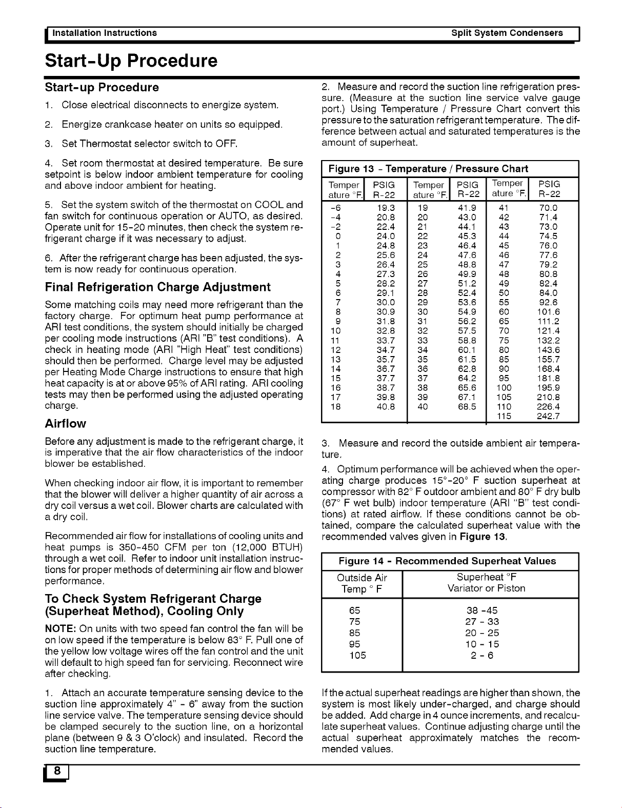
2. Measure and record the suction line refrigeration pres-
sure. (Measure at the suction line service valve gauge
port.) Using Temperature / Pressure Chart convert this
pressuretothe saturation refrigerant temperature. The dif-
ference between actual and saturated temperatures is the
amount of superheat.
4. Set room thermostat at desired temperature. Be sure
setpoint is below indoor ambient temperature for cooling
and above indoor ambient for heating.
5. Set the system switch of the thermostat on COOL and
fan switch for continuous operation or AUTO, as desired.
Operate unit for 15-20 minutes, then check the system re-
frigerant charge if it was necessary to adjust.
6. After the refrigerant charge has been adjusted, the sys-
tem is now ready for continuous operation.
Final Refrigeration Charge Adjustment
Some matching coils may need more refrigerant than the
factory charge. For optimum heat pump performance at
ARI test conditions, the system should initially be charged
per cooling mode instructions (ARI "B" test conditions). A
check in heating mode (ARI "High Heat" test conditions)
should then be performed. Charge level may be adjusted
per Heating Mode Charge instructions to ensure that high
heat capacity is at or above 95% of ARI rating. ARI cooling
tests may then be performed using the adjusted operating
charge.
Airflow
Figure 13
Temper
ature °F.
-6
-4
-2
0
1
2
3
4
5
6
7
8
9
10
11
12
13
14
15
16
17
18
- Temperature / Pressure Chart
PSIG Temper PSIG Temper
R-22 ature °F. R-22 ature °F.
19.3 19 41.9 41
20.8 20 43.0 42
22.4 21 44.1 43
24.0 22 45.3 44
24.8 23 46.4 45
25.6 24 47.6 46
26.4 25 48.8 47
27.3 26 49.9 48
28.2 27 51.2 49
29.1 28 52.4 50
30.0 29 53.6 55
30.9 30 54.9 60
31.8 31 56.2 65
32.8 32 57.5 70
33.7 33 58.8 75
34.7 34 60.1 80
35.7 35 61.5 85
36.7 36 62.8 90
37.7 37 64.2 95
38.7 38 65.6 100
39.8 39 67.1 105
40.8 40 68.5 110
115
PSIG
R-22
70.0
71.4
73.0
74.5
76.0
77.6
79.2
80.8
82.4
84.0
92.6
101.6
111.2
121,4
132,2
143,6
155,7
168.4
181,8
195,9
210,8
226,4
242.7
Before any adjustment is made to the refrigerant charge, it
is imperative that the air flow characteristics of the indoor
blower be established.
When checking indoor air flow, it is important to remember
that the blower will deliver a higher quantity of air across a
dry coil versus a wet coil. Blower charts are calculated with
a dry coil.
Recommended air flow for installations of cooling units and
heat pumps is 350-450 CFM per ton (12,000 BTUH)
through a wet coil. Refer to indoor unit installation instruc-
tions for proper methods of determining air flow and blower
performance.
To Check System Refrigerant Charge
(Superheat Method), Cooling Only
NOTE: On units with two speed fan control the fan will be
on low speed if the temperature is below 83° R Pull one of
the yellow low voltage wires off the fan control and the unit
will default to high speed fan for servicing. Reconnect wire
after checking.
3. Measure and record the outside ambient air tempera-
ture.
4. Optimum performance will be achieved when the oper-
ating charge produces 15°-20 ° F suction superheat at
compressor with 82 ° Foutdoor ambient and 80° Fdry bulb
(67° F wet bulb) indoor temperature (ARI "B" test condi-
tions) at rated airflow. If these conditions cannot be ob-
tained, compare the calculated superheat value with the
recommended valves given in Figure 13.
Figure 14 - Recommended Superheat Values
Outside Air Superheat °F
Temp ° F Variator or Piston
65
75
85
95
105
38 -45
27 - 33
20 - 25
10 - 15
2-6
1. Attach an accurate temperature sensing device to the
suction line approximately 4" - 6" away from the suction
line service valve. The temperature sensing device should
be clamped securely to the suction line, on a horizontal
plane (between 9 & 3 O'clock) and insulated. Record the
suction line temperature.
Ifthe actual superheat readings are higher than shown, the
system is most likely under-charged, and charge should
be added. Add charge in 4 ounce increments, and recalcu-
late superheat values. Continue adjusting charge until the
actual superheat approximately matches the recom-
mended values.
Loading ...
Loading ...
Loading ...