Loading ...
Loading ...
Loading ...
_Installation Instructions
Electrical Wiring
Electrical Shock Hazard.
Shut off electric power at fuse box or service pan-
el before making any electrical connections.
Failure to shut off electric power can result in,
property damage, personal injury and/or death.
The supply voltage should be 208-230 volts (196 volt mini-
mum to 253 volts maximum) 60Hz single phase.
APPROVED FOR USE WITH COPPER CONDUCTORS
ONLY. DO NOT USE ALUMINUM WIRE.
REFER TO UNIT RATING PLATE FOR CIRCUIT
PROTECTION.
NOTE: Some Heat Pumps will be shipped with a label over
or near the electrical entrance holes will have to have the
defrost sensor installed in the hole next to the electrical en-
trance holes. See Mount Defrost Sensor.
Grounding
Permanently ground unit in accordance with the National
Electrical Code and local codes or ordinances. Use a cop-
per conductor of the correct size from the grounding termi-
nal in control box to a grounded connection in the service
panel or a properly driven and electrically grounded ground
rod,
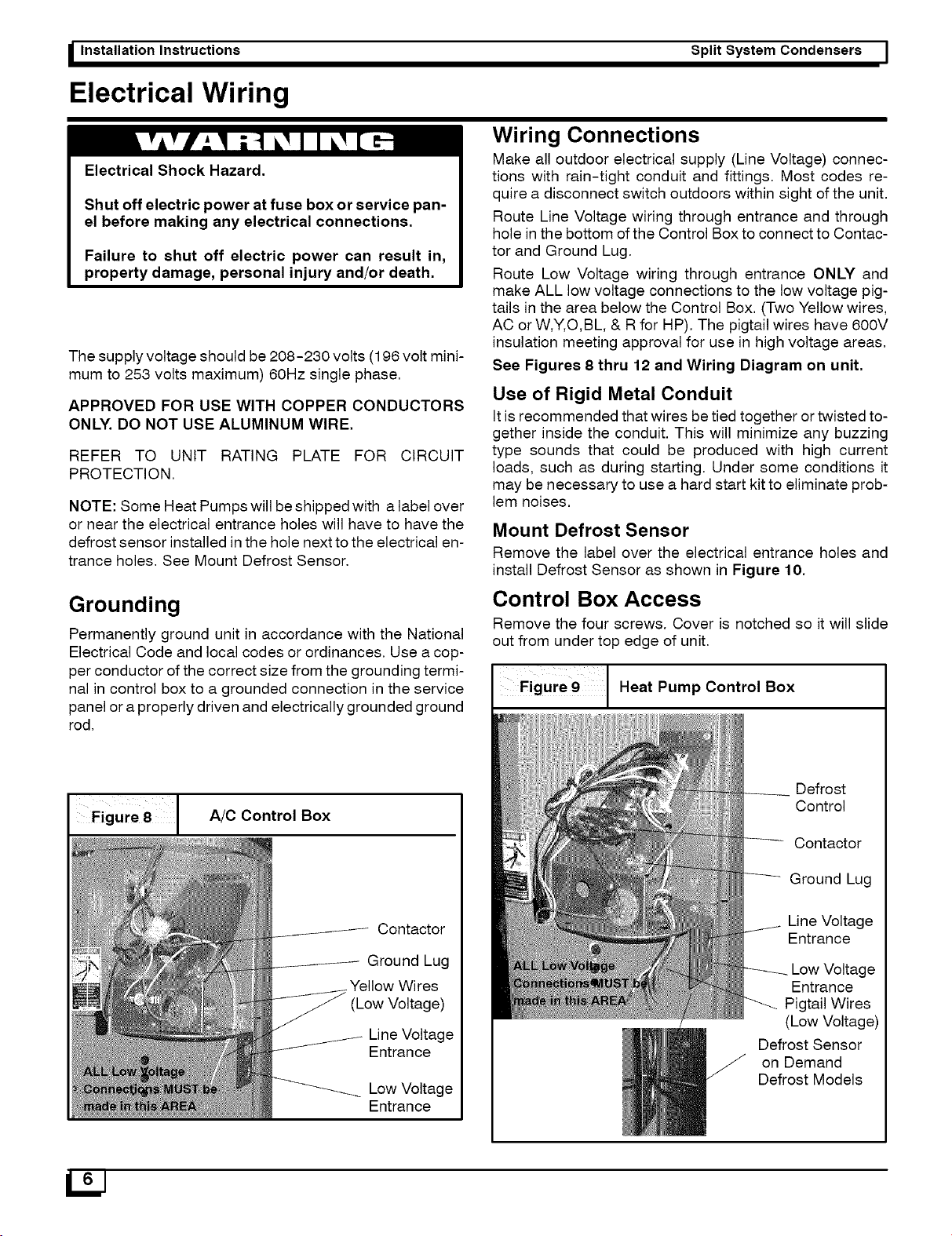
Figure 8 [ A/C Control Box
Contactor
Ground Lug
Wires
(Low Voltage)
Line Voltage
Entrance
Low Voltage
Entrance
Split System Condensers I
Wiring Connections
Make all outdoor electrical supply (Line Voltage) connec-
tions with rain-tight conduit and fittings. Most codes re-
quire a disconnect switch outdoors within sight of the unit.
Route Line Voltage wiring through entrance and through
hole in the bottom of the Control Box to connect to Contac-
tor and Ground Lug.
Route Low Voltage wiring through entrance ONLY and
make ALL low voltage connections to the low voltage pig-
tails in the area below the Control Box. (Two Yellow wires,
AC or W,Y,O,BL, & R for HP). The pigtail wires have 600V
insulation meeting approval for use in high voltage areas.
See Figures 8 thru 12 and Wiring Diagram on unit.
Use of Rigid Metal Conduit
It is recommended that wires be tied together or twisted to-
gether inside the conduit. This will minimize any buzzing
type sounds that could be produced with high current
loads, such as during starting. Under some conditions it
may be necessary to use a hard start kit to eliminate prob-
lem noises.
Mount Defrost Sensor
Remove the label over the electrical entrance holes and
install Defrost Sensor as shown in Figure 10.
Control Box Access
Remove the four screws. Cover is notched so it will slide
out from under top edge of unit.
Heat Pump Control Box
Defrost
Control
Contactor
Ground Lug
Line Voltage
Entrance
Low Voltage
Entrance
Pigtail Wires
(Low Voltage)
Defrost Sensor
on Demand
Defrost Models
LIJ
Loading ...
Loading ...
Loading ...