R
INSTRUCTION MANUAL
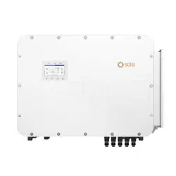
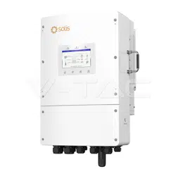
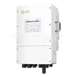
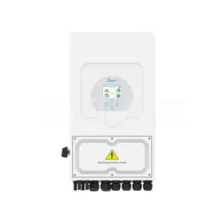
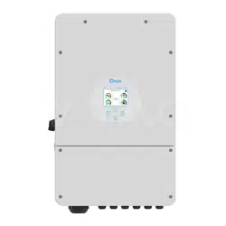
SOLAR HYBRID INVERTER
INTRODUCTION
USER MANUAL QR CODE
: SUN-8K-SG01LP1-EU
IN CASE OF ANY QUERY/ISSUE WITH THE PRODUCT, PLEASE REACH OUT TO US AT: SUPPORT@V-TAC.EU
FOR MORE PRODUCTS RANGE, INQUIRY PLEASE CONTACT OUR DISTRIBUTOR OR NEAREST
DEALERS. V-TAC EUROPE LTD. BULGARIA, PLOVDIV 4000, BUL.L.KARAVELOW 9B
MODEL
: 11803SKU
Thank you for selecting and buying V-TAC Product. V-TAC will serve you the
best. Please read these instructions carefully & keep this user manual handy
for future reference. If you have any another query, please contact our dealer
or local vendor from whom you have purchased the product. They are
trained and ready to serve you at the best.
Please scan the QR code to access the
manual in multiple languages.
WARNING
1. Safety Introductions
2. Produc Introduction
1. Please make sure to turn off the power before starting the installation.
2. Installation must be performed by a qualified electrician.
This marking indicates that this
product should not be disposed of
with other household wastes.
Caution, risk of electric shock.
• This chapter contains important safety and operating instructions. Read and keep this manual
for future reference.
• Before using the inverter, please read the instructions and warning signs of the battery and
corresponding sections in the instruction manual.
• Do not disassemble the inverter. If you need maintenance or repair, take it to a professional
service center.
• Improper reassembly may result in electric shock or fire.
• To reduce risk of electric shock, disconnect all wires before attempting any maintenance or
cleaning. Turning off the unit will not reduce this risk.
• Caution: Only qualified personnel can install this device with battery.
• Never charge a frozen battery.
• For optimum operation of this inverter, please follow required specification to select appropriate
cable size. It is very important to correctly operate this inverter.
• Be very cautious when working with metal tools on or around batteries. Dropping a tool may
cause a spark or short circuit in batteries or other electrical parts, even cause an explosion.
• Please strictly follow installation procedure when you want to disconnect AC or DC terminals.
Please refer to " Installation" section of this manual for the details.
• Grounding instructions - this inverter should be connected to a permanent grounded wiring
system. Be sure to comply with local requirements and regulation to install this inverter.
• Never cause AC output and DC input short circuited. Do not connect to the mains when DC
input short circuits.
This is a multifunctional inverter, combining functions of inverter, solar charger and battery
charger to offer uninterruptible power support with portable size. Its comprehensive LCD display
offers user configurable and easy accessible button operation such as battery charging,
AC/solar charging, and acceptable input voltage based on different applications.
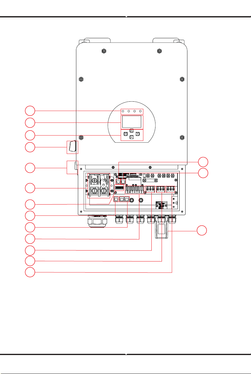
2.1 Product Overview
1: Inverter Indicators
2: LCD display
3: Function Buttons
4: DC Switch
5: Power on/o button
6: RS 485 port
7: CAN Port
8: Battery input connectors
9: Function Port
10: Meter_CON port
11: Parallel port
12: PV input with two MPPT
13: Grid
14: Generator input
15: Load
16: WiFi Interface
1
2
3
4
5
8
9
10
11
12
13
14
15
16
7
6
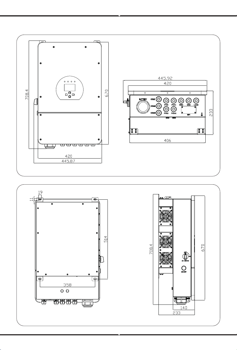
2.2 Product Size
Inverter Size
2.3 Product Features
- Self-consumption and feed-in to the grid.
- Auto restart while AC is recovering.
- Programmable supply priority for battery or grid.
- Programmable multiple operation modes: On grid, o grid and UPS.
- Configurable battery charging current/voltage based on applications by LCD setting.
- Configurable AC/Solar/Generator Charger priority by LCD setting.
- Compatible with mains voltage or generator power.
- Overload/over temperature/short circuit protection.
- Smart battery charger design for optimized battery performance
- With limit function, prevent excess power overflow to the grid.
- Supporting WIFI monitoring and build-in 2 strings of MPP trackers
- Smart settable three stages MPPT charging for optimized battery performance.
- Time of use function.
- Smart Load Function.
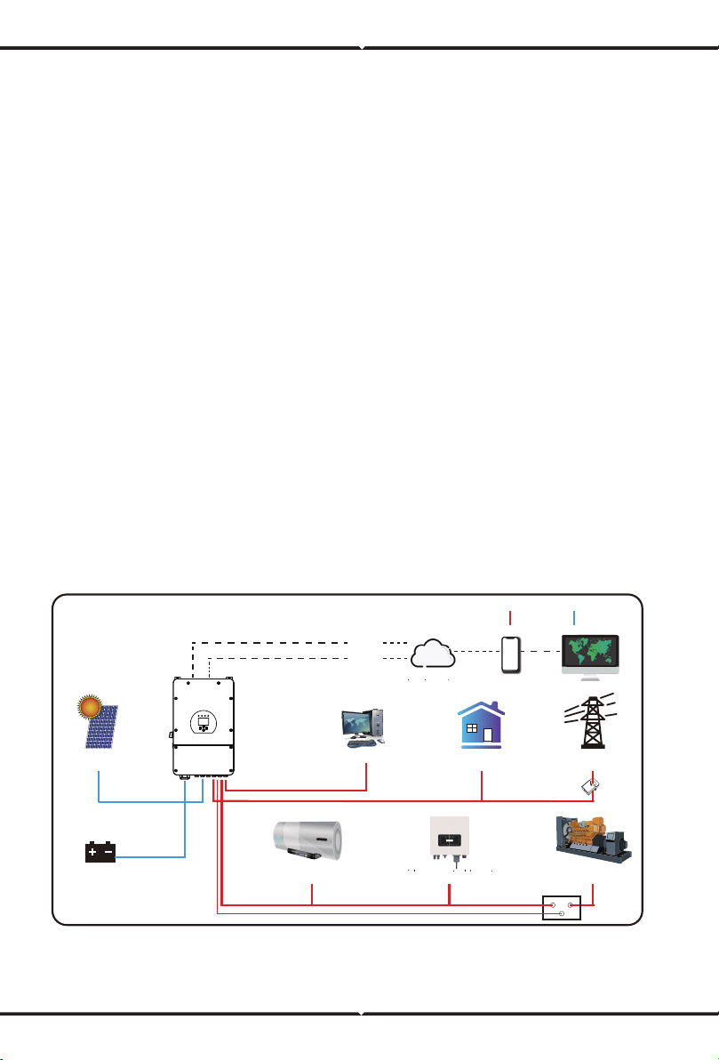
2.4 Basic System Architecture
The following illustration shows basic application of this inverter.
It also includes following devices to have a Complete running system.
- Generator or Utility
- PV modules
Consult with your system integrator for other possible system architectures depending on your
requirements.
This inverter can power all kinds of appliances in home or oce environment, including motor
type appliances such as refrigerator and air conditioner.
GridBackup Load
WiFI
GPRS
phoneCloud services
On-Grid Home Load
Generator
ATS
Grid-connected InverterSmart Load
Battery
Solar
CT
AC cable DC cable
Grid-connected Inverter
Cloud services
3. Installation
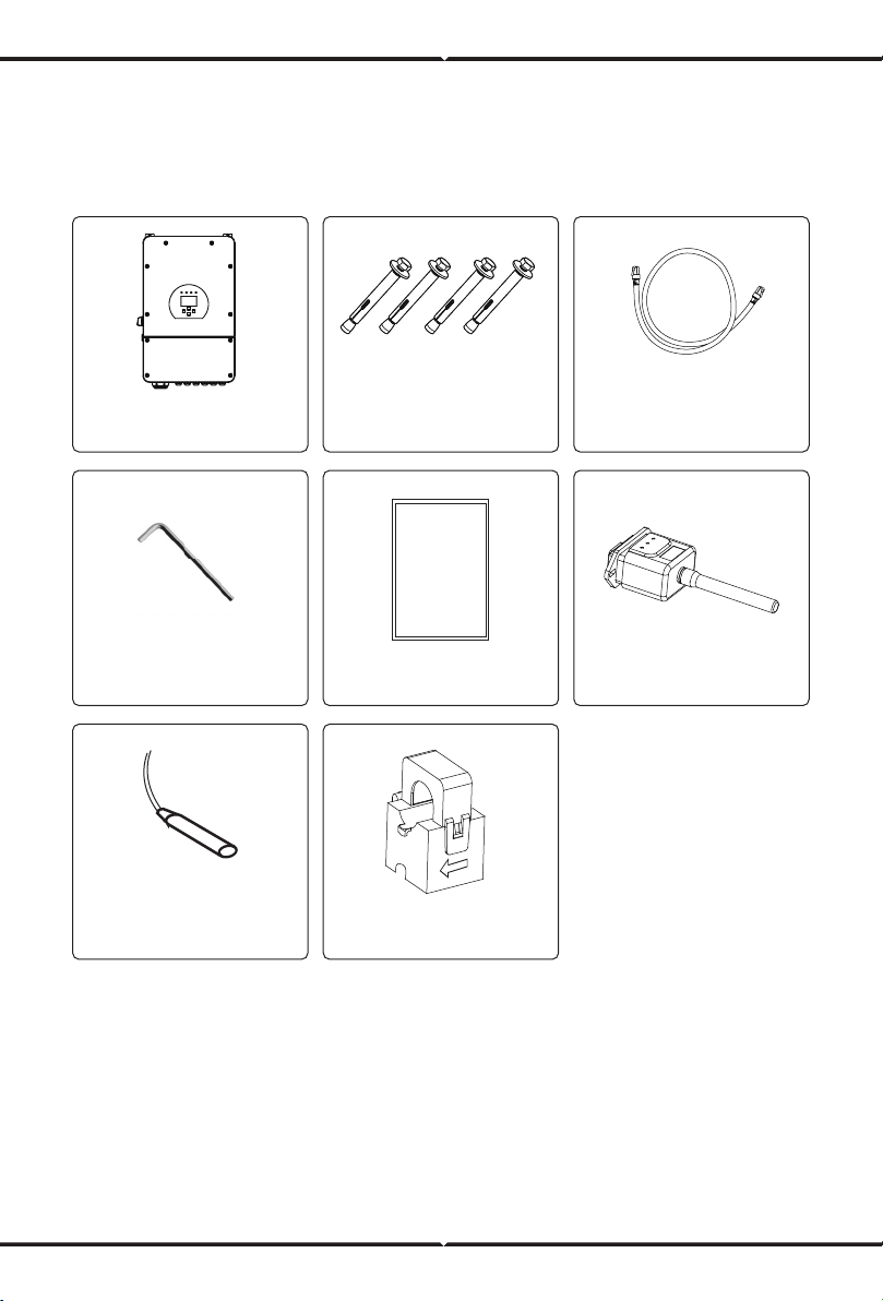
3.1 Parts List
Check the equipment before installation. Please make sure nothing is damaged in the package.
You should have received the items in the following package:
Parallel communication
cable x1
Hybrid inverter
x1
L-type Hexagon wrench
x1
Stainless steel anti-collision
bolt M8×80
x4
Battery temperature sensor
x1
User
manual
User manual x1 Wi-Fi-Plug(optional) x1
Sensor Clamp
US x2 / EU x1
3.2 Mounting Instructions
Installation Precaution
This Hybrid inverter is designed for outdoor use(IP65), Please make sure the installation site
meets below conditions:
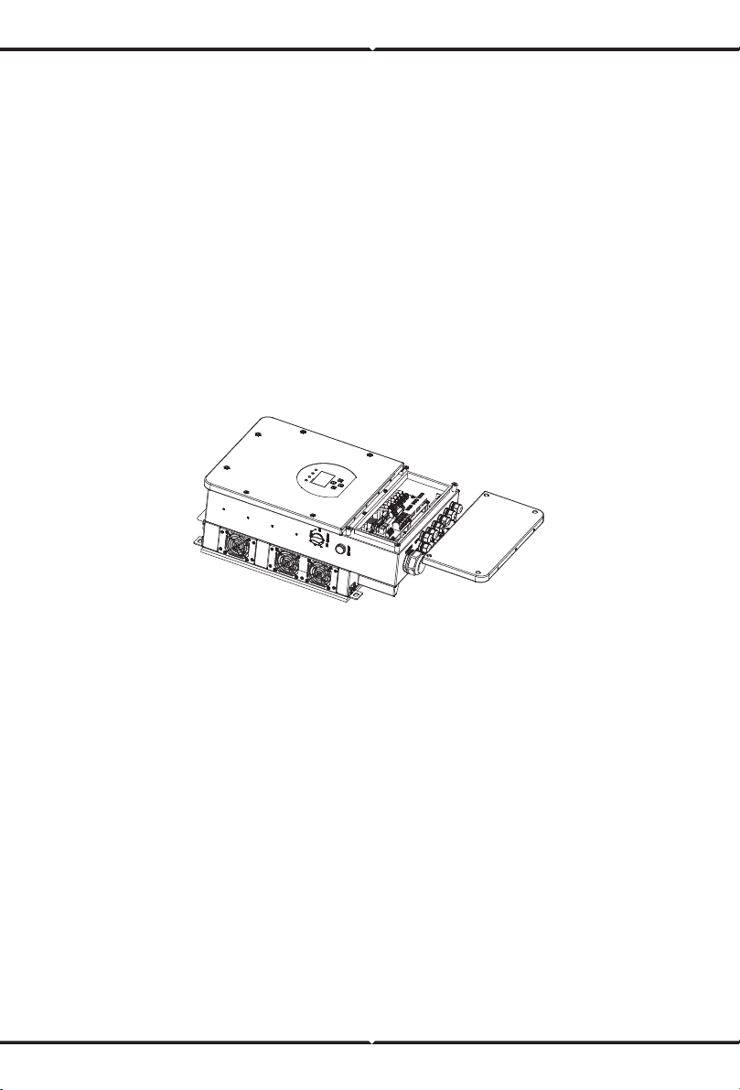
Please AVOID direct sunlight, rain exposure, snow laying up during installation and
operation. Before connecting all wires, please take o the metal cover by removing
screws as shown below:
· Not in direct sunlight
· Not in areas where highly flammable materials are stored.
· Not in potential explosive areas.
· Not in the cool air directly.
· Not near the television Antenna or antenna cable.
· Not higher than altitude of about 2000 meters above sea level.
· Not in environment of precipitation or humidity(>95%)
Considering the following points before selecting where to install:
· Please select a vertical wall with load-bearing capacity for installation, suitable for installation
on concrete or other non-flammable surfaces,installation is shown below.
· Install this inverter at eye level in order to allow the LCD display to be read at all times.
· The ambient temperature is recommeded to be between -40~60℃ to ensure optimal operation.
· Be sure to keep other objects and surfaces as shown in the diagram to guarantee sucient
heat dissipation and have enough space for removing wires.
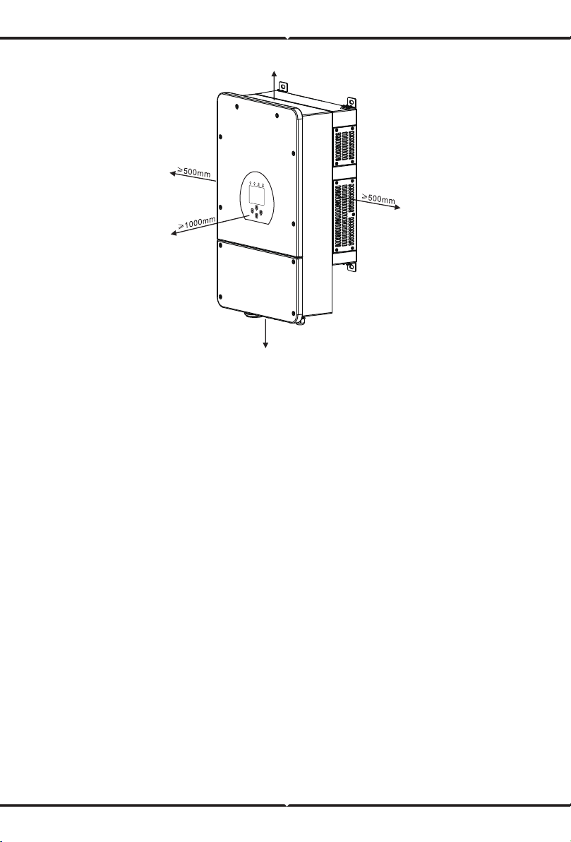
For proper air circulation to dissipate heat, allow a clearance of approx. 50cm to the side and
approx. 50cm above and below the unit. And 100cm to the front.
Mounting the inverter
Remember that this inverter is heavy! Please be careful when liing out from the package.
Choose the recommend drill head(as shown in below pic) to drill 4 holes on the wall,
82-90mm deep.
1. Use a proper hammer to fit the expansion bolt into the holes.
2. Carry the inverter and holding it, make sure the hanger aim at the expansion bolt,fix the
inverter on the wall.
3. Fasten the screw head of the expansion bolt to finish the mounting.
≥ 500mm
≥ 500mm
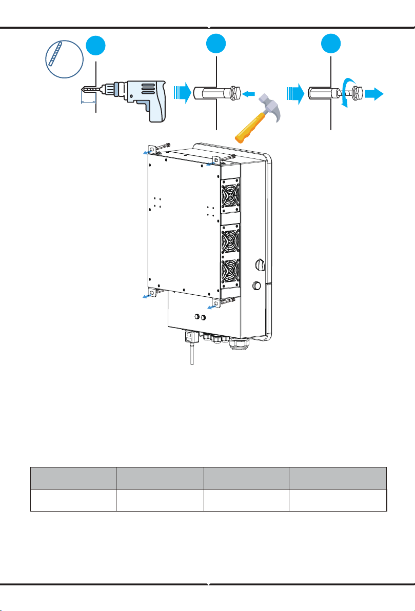
12 mm
82~90mm
[(3.23 in.)to(3.54 in.)]
( 0.47 in.)
1
2 3
3.3 Battery connection
Chart 3-2 Cable size
For safe operation and compliance, a separate DC over-current protector or disconnect device is
required between the battery and the inverter. In some applications, switching devices may not
be required but over-current protectors are still required. Refer to the typical amperage in the
table below for the required fuse or circuit breaker size.
Model
8Kw
Wire Size
1AWG
Cable(mm )
2
50
Torque value(max)
24.5Nm
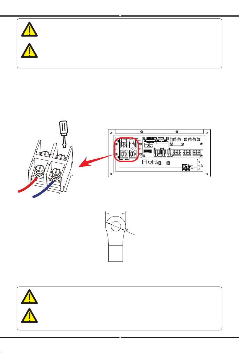
For 7.6KW/8KW model, battery connector screw size: M10
Please follow below steps to implement battery connection:
1. Please choose a suitable battery cable with correct connector which can well fit into the
battery terminals.
2. Use a suitable screwdriver to unscrew the bolts and fit the battery
connectors in, then fasten the bolt by the screwdriver, make sure the bolts are tightened
with torque of 24.5 N.M in clockwise direction
3. Make sure polarity at both the battery and inverter is correctly connected.
Connecting the battery with a suitable cable is important for safe and ecient
operation of the system. To reduce the risk of injury, refer to Chart 3-2 for
recommended cables.
All wiring must be performed by a professional person.
4. In case of children touch or insects go into the inverter, Please make sure the inverter
connector is fasten to waterproof position by twist it clockwise.
Before making the final DC connection or closing DC breaker/disconnect, be sure
positive(+) must be connect to positive(+) and negative(-) must be connected to
negative(-). Reverse polarity connection on battery will damage the inverter.
Installation must be performed with care.
29.54
22mm
10.5mm
DC Battery Input
30mm
30mm

3.3.2 Function port definition
Batt Temp
Sensor
1 2 3 4 5 6 7 8 9 10
RS 485
Meter_CON Parallel_A Parallel_B
CAN
TEMP (1,2): battery temperature sensor for
lead acid battery.
CT-L1 (3,4): current transformer (CT1) for
“zero export to CT”mode clamps
on L1 when in split phase system.
CT-L2 (5,6): current transformer (CT2) for
“zero export to CT”mode clamps
on L2 when in split phase system.
G-start (7,8): dry contact signal for startup
the diesel generator.
When the "GEN signal" is active, the open
contact (GS) will switch on (no voltage output).
G-valve (9,10): reserved.
RSD (11,12): provide 12Vdc output when
inverter is on.
ATS: 230V output port when inverter is on
Note: For - EU model (7.6/8kW,230V@50Hz),
1pcs CT is needed only, and the secondary
side of the CT should be connected to
5&6 port (CT-L2).
CT -L1
CT -L2
Gen start-up
N/O Relay
Neutral
Earth
Bond
240V Coil
3.3.2 Function port definition
3.3.2 Function port definition
Inverter
RS 485
RS 485
11 12 ATS
GS (diesel generator startup signal)
relay
coil
open
contact
G S
RS 485: RS 485 port for battery
communication.
CAN: CAN port for battery
communication.
Parallel A: Parallel communication port 1
(CAN interface).
Parallel B: Parallel communication port 2
(CAN interface).
*Meter_CON: for energy meter communication.
*Some hardware versions don't
have this port.
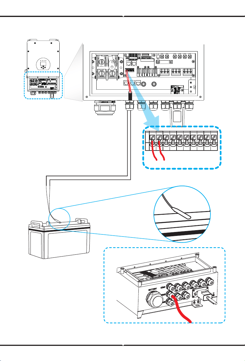
3.3.3 Temperature sensor connection for lead-acid battery
1 2
Temp. sensor
3.4 Grid connection and backup load connection
Please follow below steps to implement AC input/output connection:
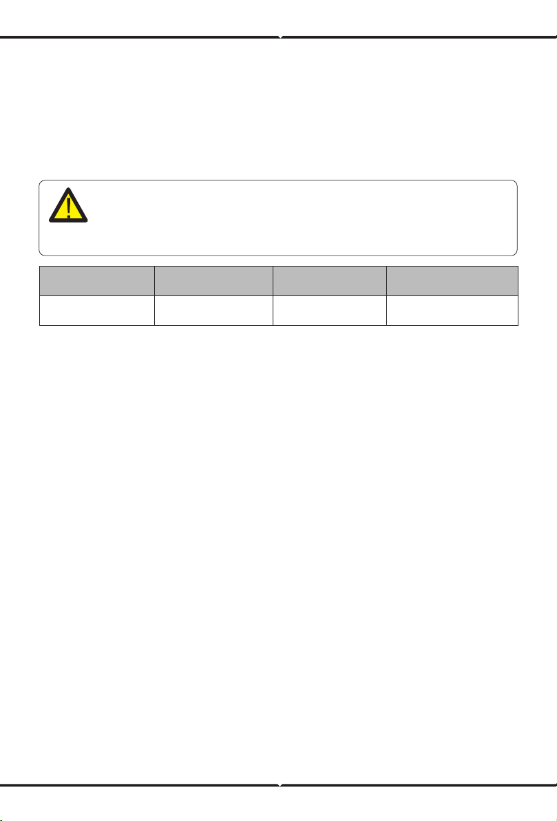
Chart 3-3 Recommended Size for AC wires
· Before connecting to grid, please install a separate AC breaker between inverter and grid. Also,
it is recommended that installs an AC breaker between backup load and inverter.This will ensure
the inverter can be securely disconnected during maintenance and fully protected from over
current. The recommended of AC breaker is 40A for 5kw and 63A for 8KW.
· There are three terminal blocks with "Grid" "Load"and "GEN" markings. Please do not misconnect
input and output connectors.
All wiring must be performed by a qualified personnel.It is very important for
system safety and ecient operation to use appropriate cable for AC input
connection. To reduce risk of injury, please use the proper recommended cable
as below.
Model
8KW
Wire Size
10AWG
Cable(mm )
2
6
Torque value(max)
1.2Nm
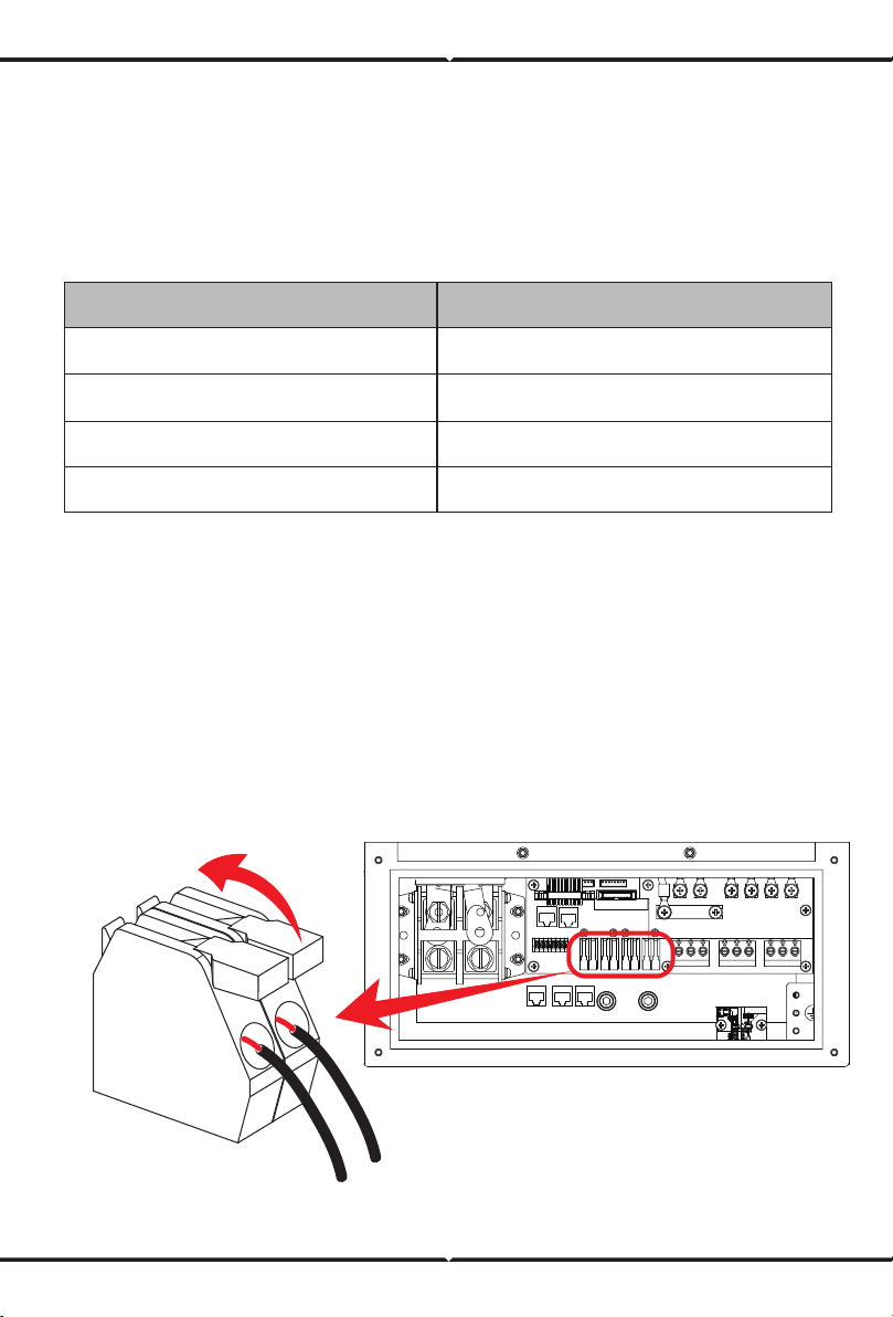
1. Before making Grid, load and Gen port connection, be sure to turn o AC breaker or
disconnector first.
2. Remove insulation sleeve 10mm length, unscrew the bolts, insert the wires according to
polarities indicated on the terminal block and tighten the terminal screws. Make sure the
connection is complete.

GRID
LOAD
GEN PORT
(Region:EU)
GRID
N
L
N
L
N
L
LOADGEN PORT

3.5 PV Connection
3. Then, insert AC output wires according to polarities indicated on the terminal block and tighten
terminal. Be sure to connect corresponding N wires and PE wires to related terminals as well.
4. Make sure the wires are securely connected.
5. Appliances such as air conditioner are required at least 2-3 minutes to restart because it is
required to have enough time to balance refrigerant gas inside of circuit. If a power shortage
occurs and recovers in short time, it will cause damage to your connected appliances. To
prevent this kind of damage, please check manufacturer of air conditioner if it is equipped with
time-delay function before installation. Otherwise, this inverter will trigger overload fault and
cut o output to protect your appliance but sometimes it still causes internal damage to the air
conditioner
Before connecting to PV modules, please install a separately DC circuit breaker between
inverter and PV modules. It is very important for system safety and ecient operation to
use appropriate cable for PV module connection. To reduce risk of injury, please use the
proper recommended cable size as below.
Chart 3-4 Cable size
Be sure that AC power source is disconnected before attempting to wire it to the
unit.
To avoid any malfunction, do not connect any PV modules with possible current
leakage to the inverter. For example, grounded PV modules will cause current
leakage to the inverter. When using PV modules, please ensure the PV+ & PV- o
f solar panel is not connected to the system ground bar.
It is requested to use PV junction box with surge protection. Otherwise, it will
cause damage on inverter when lightning occurs on PV modules.
Model
8KW
Wire Size
12AWG
Cable(mm )
2
4
3.5.1 PV Module Selection:
3.5.2 PV Module Wire Connection:
When selecting proper PV modules, please be sure to consider below parameters:
1) Open circuit Voltage (Voc) of PV modules not exceeds max. PV array open circuit voltage of
inverter.
2) Open circuit Voltage (Voc) of PV modules should be higher than min. start voltage.
3) The PV modules used to connected to this inverter shall be Class A rating certified according
to lEC 61730.
Please follow below steps to implement PV module connection:
1. Remove insulation sleeve 10 mm for positive and negative conductors.
2. Suggest to put bootlace ferrules on the end of positive and negative wires with a proper
crimping tool.
3. Check correct polarity of wire connection from PV modules and PV input connectors. Then,
connect positive pole (+) of connection wire to positive pole (+) of PV input connector. Connect
negative pole (-) of connection wire to negative pole(-)of PV input connector. Close the switch
and make sure the wires are tightly fixed.
Chart 3-5
PV Input Voltage
Inverter Model 8KW
370V (125V~500V)
150V-425VPV Array MPPT Voltage Range
No. of MPP Trackers
No. of Strings per MPP Tracker
2
2+2

3.6 CT Connection
The primary side of the CT
needs to be clamped on the
Grid live line.
If the data read by the CT is wrong, you can try to point
the direction of the CT to the grid.
(Region:EU)
Inverter
N L
N L N L N L
White wire
5 6
Black wire
Grid
L
N
CT
5
6
Load
GEN
Grid
CT
Arrow pointing
to
inverter
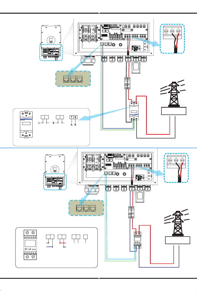
3.6.1 Meter Connection
1
230V/2T
5 6 7 8 9 10
2
3
A B
4
GND
1+COM 2+
Inverter
N L
N L N L N L
Grid
Load
GEN
Grid
AC
Breaker
L
N
RS485
Meter_CON Parallel_A Parallel_B
System connection diagram for the Eastron meter
Output
RS 485 GND
Input
Pic 7.1 EASTRON meter
EASTRON SDM230
1
230V/2T
5 6 7 8 9 10
2
3
A B
4
GND
1+COM 2+
5
3
6
7
GNDA B
L
N
L
N
1
2 4
RS485B
RS485A
DDSU666 DIN-RAIL METER
230V 5(60) A 800imp/kWh
2
56
1
4
7
8
3
(Region:EU )
Inverter
N L
N L N L N L
Grid
Load
GEN
Grid
AC
Breaker
System connection diagram for the CHNT meter
21 43
CHNT DDSU666
DDSU666 DIN-RAIL METER
230V 5(60) A 800imp/kWh
2
5 6
1
4
7 8
3
Output
RS 485
Grid input
CHINT meter
L
N
Meter_CON Parallel_A Parallel_B
RS485B
RS485A
3.8 WIFI Connection
For the configuration of Wi-Fi Plug, please refer to illustrations of the Wi-Fi Plug. The Wi-Fi Plug
is not a standard configuration, it's optional.
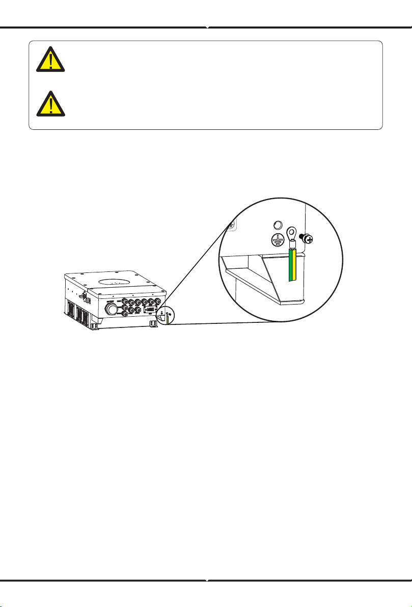
3.7 Earth Connection(mandatory)
Ground cable shall be connected to ground plate on grid side this prevents electric shock. if the
original protective conductor fails.
Note:
When the inverter is in the o-grid state, the N line needs to be connected to the
earth.
Note:
In final installation,breaker certified according to IEC 60947-1 and IEC 60947-2
shall be installed with the equipment.

3.9 Wiring System for Inverter
(Region:EU)
E-BAR
E-BAR
AC Breaker
AC Breaker AC Breaker
Load
L L
N
PE
N
PE
Battery
Diesel
generator
Diesel
generator
BMS
Load
L N PE
Grid
L L
N
PE
N
PE
Grid
CT
CT
Home Loads
Hybrid Inverter
AC Breaker
DC Breaker
PV
DC Breaker
E-BAR
E-BAR
N-BAR
AC Breaker
AC Breaker AC Breaker
Load
L L
N
PE
or
N
PE
Battery
PV
BMS
Load
L N PE
Grid
L L
N
PE
N
PE
Grid
CT
CT
Home Loads
Hybrid Inverter
AC Breaker
DC Breaker
DC Breaker
Do not connect this terminal
when the neutral wire and PE
wire are connected together.
E-N
Link
This diagram is an example for application that Neutral connects together with
PE in distribution box.
Such as: Australia, New Zealand, South Africa, etc. (Please follow local wiring
regulations!)
This diagram is an example for grid systems without special requirements on
electrical wiring connection.
Note: The back-up PE line and earthing bar must be grounded properly and
eectively.
Otherwise the back-up function may be abnormal when the grid fails.

(Region:EU)
L wireCAN N wire PE wire
3.10 Typical application diagram of diesel generator
N L N L N L
Load
GEN
Grid
Inverter
Battery pack
① DC
Breaker
Backup Load
L
N
PE
LNPE
Ground
Generator
2
3
7 8
Inverter
① DC Breaker for battery
SUN 8K-SG: 250A DC breaker
G-start (7,8): dry contact signal for startup
the diesel generator.
GS (diesel generator startup signal)
relay
coil
open
contact
G S
AC Breaker for gen port
SUN 8K-SG: 63A AC breaker
2
Remotely control signal line
Inverter
3
AC Breaker for backup load port
SUN 8K-SG: 63A AC breaker
(Region:EU)
L wireCAN N wire PE wire
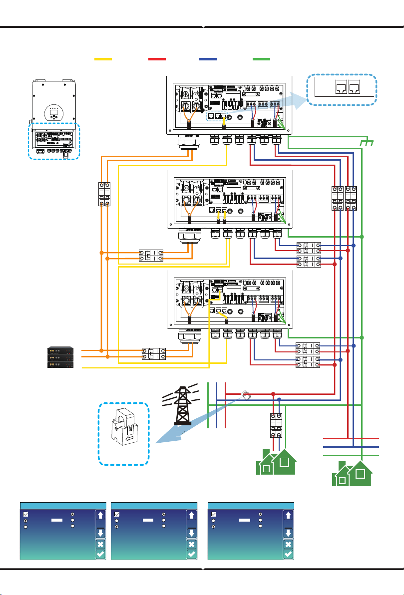
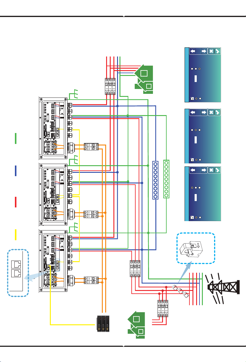
3.11 Single phase (230Vac) parallel connection diagram
N L N L N L
Load
GEN
Grid
Parallel
Master
Slave
Modbus SN
01
A Phase
B Phase
C Phase
Advanced Function
Paral.
Set3
Parallel
Master
Slave
Modbus SN
02
A Phase
B Phase
C Phase
Advanced Function
Paral.
Set3
Parallel
Master
Slave
Modbus SN
03
A Phase
B Phase
C Phase
Advanced Function
Paral.
Set3
Master inverter Slave Inverter Slave Inverter
Parallel AParallel B
Inverter
No.3
(slave)
Inverter
No.2
(slave)
Inverter
No.1
(master)
Battery pack
① DC
Breaker
② DC
Breaker
③ DC
Breaker
Grid
Backup Load
L
N
PE
LNPE
Ground
Home Load
④
⑥
⑨
⑩
Grid
①②③ DC Breaker for battery
⑤⑦⑨ AC Breaker for grid port
④⑥⑧ AC Breaker for
backup load port
⑩ AC Breaker
Depends on Home Load
SUN 8K-SG: 63A AC breaker
⑦
⑤
⑧
CT
Arrow pointing
to inverter
The primary side of the CT
needs to be clamped on the
Grid live line.
N L N L N L
Load
GEN
Grid
N L
N L
N L
Load
N L N L N L
Load
GEN
Grid
Inverter
SUN 8K-SG: 250A DC breaker
SUN 8K-SG: 63A AC breaker
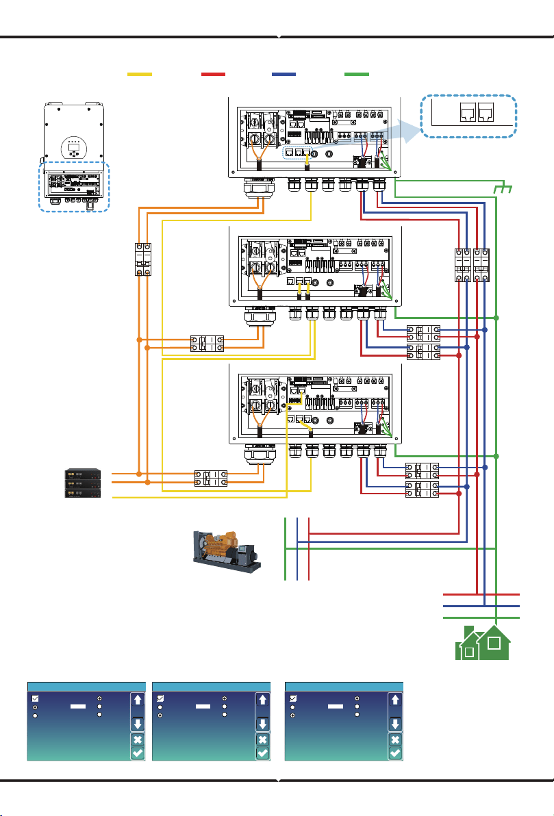
(Region:EU)
L wireCAN N wire PE wire
N L N L N L
Load
GEN
Grid
Parallel
Master
Slave
Modbus SN
01
A Phase
B Phase
C Phase
Advanced Function
Paral.
Set3
Parallel
Master
Slave
Modbus SN
02
A Phase
B Phase
C Phase
Advanced Function
Paral.
Set3
Parallel
Master
Slave
Modbus SN
03
A Phase
B Phase
C Phase
Advanced Function
Paral.
Set3
Master inverter Slave Inverter Slave Inverter
Parallel AParallel B
Inverter
No.3
(slave)
Inverter
No.2
(slave)
Inverter
No.1
(master)
Battery pack
① DC
Breaker
② DC
Breaker
③ DC
Breaker
Backup Load
L
N
PE
LNPE
Ground
④
⑥
⑨
①②③ DC Breaker for battery
⑤⑦⑨ AC Breaker for GEN port
④⑥⑧ AC Breaker for
backup load port
SUN 8K-SG: 63A AC breaker
⑦
⑤
⑧
N L N L N L
Load
GEN
Grid
N L
N L
N L
Load
N L N L N L
Load
GEN
Grid
Inverter
Generator
SUN 8K-SG: 250A DC breaker
SUN 8K-SG: 63A AC breaker
L wireCAN N wire PE wire
Battery pack
Grid
L1
L2
L3
N
PE
LoadGENGrid LoadGENGrid LoadGENGrid
A Phase Inverter No.1(master) B Phase Inverter No.2(master) C Phase Inverter No.3(master)
L3
L2
L1
N
PE
Parallel AParallel B
A Phase
Parallel A
3.12 Parallel connection for 230/400 three phase
Parallel
Master
Slave
Modbus SN
01
A Phase
B Phase
C Phase
Advanced Function
Paral.
Set3
Parallel
Master
Slave
Modbus SN
02
A Phase
B Phase
C Phase
Advanced Function
Paral.
Set3
Parallel
Master
Slave
Modbus SN
03
A Phase
B Phase
C Phase
Advanced Function
Paral.
Set3
A Phase Master inverter B Phase Master inverter C Phase Master inverter
CAN/RS 485
Backup Load
E-BAR
N-BAR
Home load
CT
CT3
CT2
CT1
Arrow pointing
to inverter
⑥ AC Breaker
⑥ AC Breaker
Depends on Home Load
⑤ AC Breaker
⑤ AC Breaker for grid port
SUN 8K-SG: 63A AC breaker
①②③ DC Breaker for battery
SUN 8K-SG: 250A DC breaker
④ AC Breaker
④ AC Breaker for backup load port
① DC
Breaker
② DC
Breaker
③ DC
Breaker
Ground
SUN 8K-SG: 63A AC breaker
(Region:EU)

N L N L N L
Load
GEN
Grid
N L N L N L
Load
GEN
Grid
L wireCAN N wire PE wire
Battery pack
L1
L2
L3
N
PE
A Phase Inverter No.1(master) B Phase Inverter No.2(master) C Phase Inverter No.3(master)
L3
L2
L1
N
PE
Parallel AParallel B
A Phase
Parallel A
Parallel
Master
Slave
Modbus SN
01
A Phase
B Phase
C Phase
Advanced Function
Paral.
Set3
Parallel
Master
Slave
Modbus SN
02
A Phase
B Phase
C Phase
Advanced Function
Paral.
Set3
Parallel
Master
Slave
Modbus SN
03
A Phase
B Phase
C Phase
Advanced Function
Paral.
Set3
A Phase Master inverter B Phase Master inverter C Phase Master inverter
CAN/RS 485
Backup Load
E-BAR
N-BAR
⑤ AC Breaker
④ AC Breaker
⑤ AC Breaker for GEN port
SUN 8K-SG: 63A AC breaker
①②③ DC Breaker for battery
SUN 8K-SG: 250A DC breaker
④ AC Breaker for backup load port
① DC
Breaker
② DC
Breaker
③ DC
Breaker
Ground
Generator
N L N L N L
Load
GEN
Grid
SUN 8K-SG: 63A AC breaker
(Region:EU)
3.13 3pcs in parallel with diesel generator
4. OPERATION
4.1 Power ON/OFF
Once the unit has been properly installed and the batteries are connected well, simply press
On/O button(located on the le side of the case) to turn on the unit. When system without
battery connected, but connect with either PV or grid, and ON/OFF button is switched o, LCD
will still light up(Display will show OFF), In this condition, when switch on ON/OFF button and
select NO battery,system can still working.
4.2 Operation and Display Panel
The operation and display panel, shown in below chart, is on the front panel of the inverter.
It includes four indicators, four function keys and a LCD display, indicating the operating status
and input/output power information.
Chart 4-1 LED indicators
LED Indicator
DC
AC
Normal
Alarm
Green led solid light
Green led solid light
Green led solid light
Red led solid light
PV Connection normal
Grid Connection normal
Inverter operating normal
Malfunction or warning
Messages
Chart 4-2 Function Buttons
Function Key
Esc
Up
Down
Enter
Description
To exit setting mode
To go to previous selection
To go to next selection
To confirm the selection
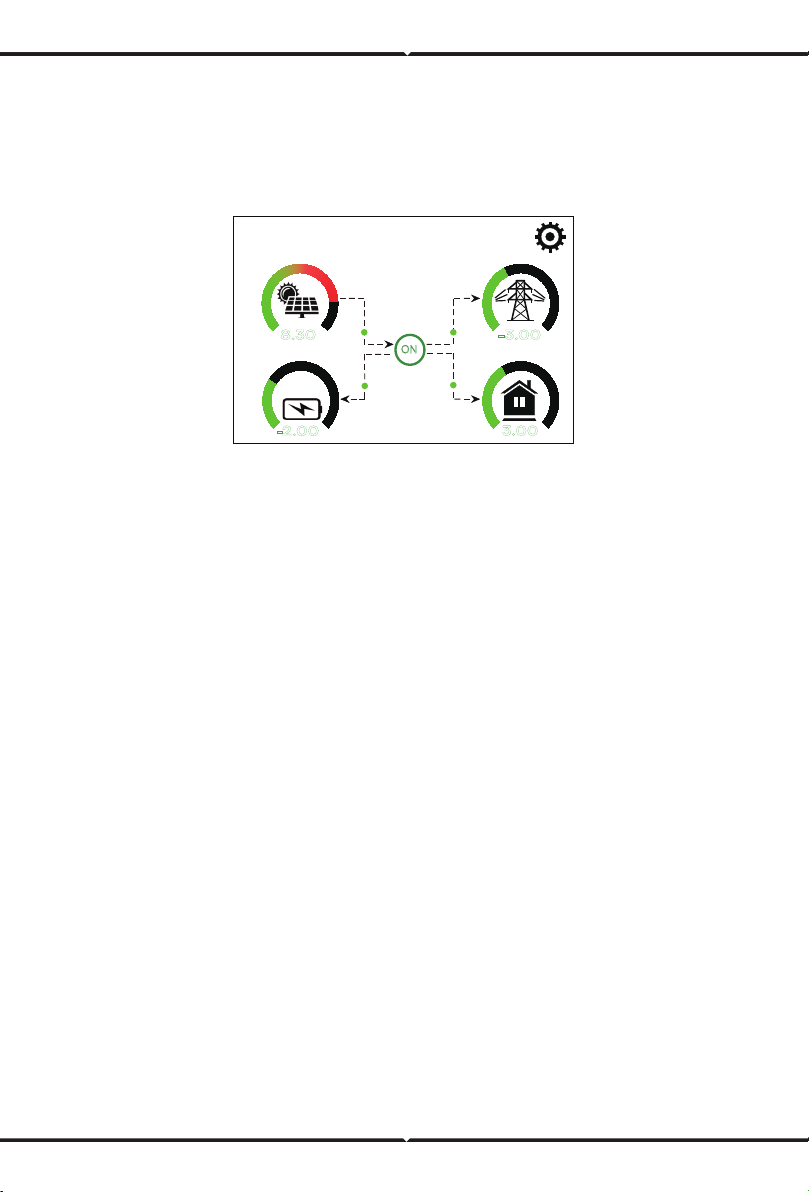
5.1 Main Screen
5. LCD Display Icons
The LCD is touchscreen, below screen shows the overall information of the inverter.
1.The icon in the center of the home screen indicates that the system is Normal operation. If it
turns into "comm./F01~F64" , it means the inverter has communication errors or other errors,
the error message will display under this icon(F01-F64 errors, detail error info can be viewed in
the System Alarms menu).
2.At the top of the screen is the time.
3.System Setup Icon, Press this set button,you can enter into the system setup screen which
including Basic Setup, Battery Setup, Grid Setup, System Work Mode, Generator port use,
Advanced function and Li-Batt info.
4.The main screen showing the info including Solar, Grid, Load and Battery. Its also displaying the
energy flow direction by arrow. When the power is approximate to high level, the color on the
panels will changing from green to red so system info showing vividly on the main screen.
· PV power and Load power always keep positive.
· Grid power negative means sell to grid, positive means get from grid.
· Battery power negative means charge, positive means discharge.
25%
05/28/2019 15:34:40
8.30
KW
-2.00
KW
-3.00
KW
3.00
KW
0 12
0 8
0 8
0 8
ON
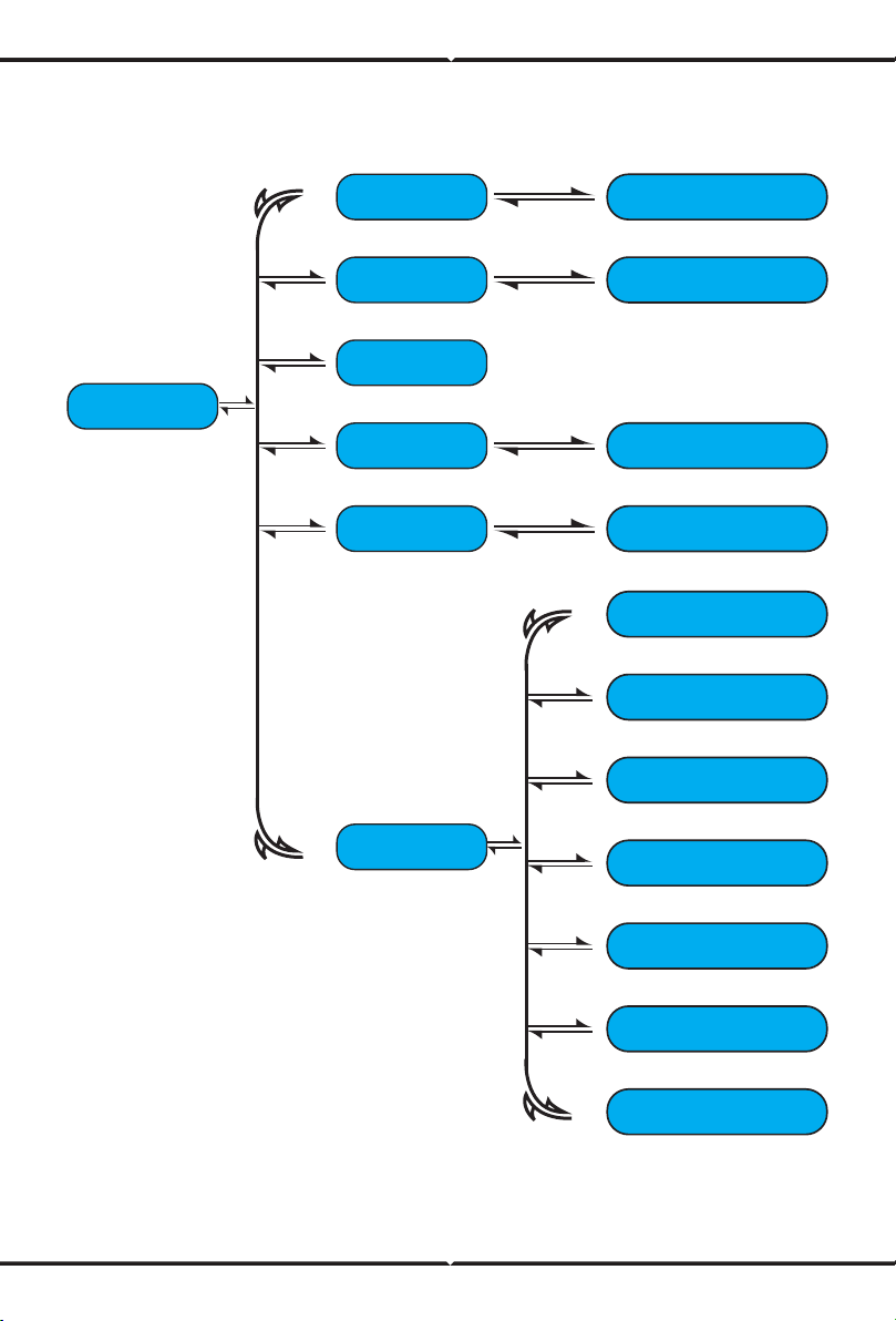
5.1.1 LCD operation flow chart
Main Screen
Solar Page Solar Graph
Grid Graph
BMS Page
Load Graph
Battery Setting
System Work Mode
Grid Setting
Gen Port Use
Basic Setting
Advanced Function
Device info
Grid Page
Inverter Page
Battery Page
Load Page
System Setup
Power: 0W
Stand-by
0.0Hz
Energy
CT1: 0W
L1: 0V L2: 0V
BUY
Today=0.0KWH
Total =8.60 KWH
Today=2.2KWH
Total =11.60 KWH
SELL
LD1: 0W
CT2: 0W
LD2: 0W
Grid
①
②
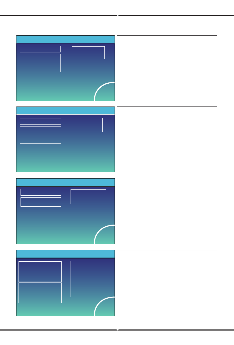
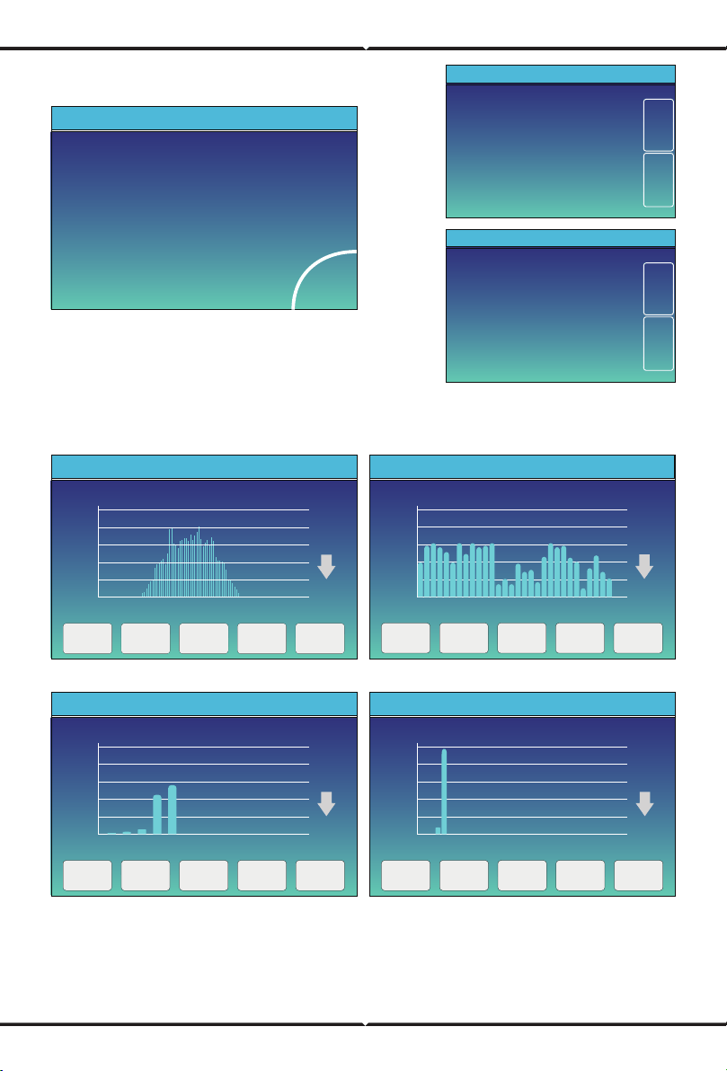
5.2 Solar Power Curve
Power: 1560W
Energy
PV1-V: 286V PV2-V: 45V
Today=8.0 KWH
Total =12.00 KWH
PV1-|: 5.5A PV2-|: 0.0A
P1: 1559W P2: 1W
Solar
This is Solar Panel detail page.
Press the “Energy “button will enter into the power
curve page.
③
①
②
③
Solar Panel Generation.
Voltage, Current, Power for each MPPT.
Solar Panel energy for Day and Total.
③
This is Grid detail page.
Press the “Energy “ button will enter into the power
curve page.
①
②
③
Status, Power, Frequency.
CT1&CT2: External Current Sensor Power
BUY: Energy from Grid to Inverter,
L1&L2: Voltage for each Phase
LD1&LD2: Internal Current Sensor Power.
SELL: Energy from Inverter to Grid.
①
②
Power: 44W DC-T:52.6C
AC-T:41.0CL1: 240V
l1:0.6A
Inverter This is Inverter detail page.
③
①
②
③
Inverter Generation.
Voltage, Current, Power for each Phase.
*DC-T: mean DC-DC temperature,
*Note: this part info is not avaiable for some
LCD FW.
AC-T: mean Heat-sink temperature.
①
②
Power: 0W Today=0.0 KWH
Total =0.40 KWHL: 0V
Load
Energy
①
②
This is Back-up Load detail page.
Press the “Energy “ button will enter into the power
curve page.
③
①
②
③
Back-up Power.
Voltage, Power for each Phase.
Back-up consumption for Day and Total.
Stand-by
SOC: 36%
U:50.50V
I:-58.02A
Power: -2930W
Temp:30.0C
Batt
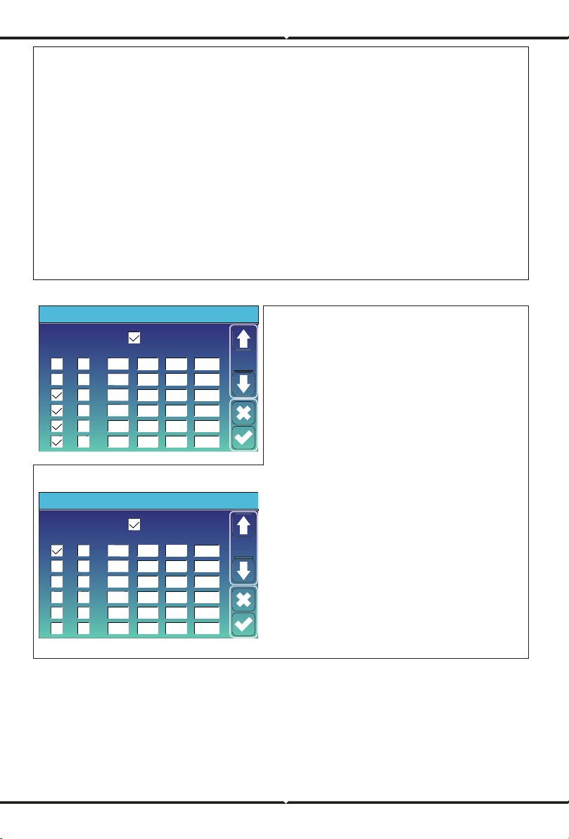
Li-BMS
Mean Voltage:50.34V Charging Voltage :53.2V
Total Current:55.00A Discharging Voltage :47.0V
Mean Temp :23.5C Charging current :50A
Total SOC :38% Discharging current :25A
Sum
Data
Details
Data
Dump Energy:57Ah
Li-BMS
Volt
1
2
3
50.38V 19.70A 30.6C 52.0% 26.0Ah 0.0V 0.0A 0|0|0
50.33V 19.10A 31.0C 51.0% 25.5Ah 53.2V 25.0A 0|0|0
50.30V 16.90A 30.2C 12.0% 6.0Ah 53.2V 25.0A 0|0|0
4
5
0.00V 0.00A 0.0C 0.0% 0.0Ah 0.0V 0.0A 0|0|0
0.00V 0.00A 0.0C 0.0% 0.0Ah 0.0V 0.0A 0|0|0
0.00V 0.00A 0.0C 0.0% 0.0Ah 0.0V 0.0A 0|0|0
0.00V 0.00A 0.0C 0.0% 0.0Ah 0.0V 0.0A 0|0|0
0.00V 0.00A 0.0C 0.0% 0.0Ah 0.0V 0.0A 0|0|0
0.00V 0.00A 0.0C 0.0% 0.0Ah 0.0V 0.0A 0|0|0
0.00V 0.00A 0.0C 0.0% 0.0Ah 0.0V 0.0A 0|0|0
0.00V 0.00A 0.0C 0.0% 0.0Ah 0.0V 0.0A 0|0|0
0.00V 0.00A 0.0C 0.0% 0.0Ah 0.0V 0.0A 0|0|0
0.00V 0.00A 0.0C 0.0% 0.0Ah 0.0V 0.0A 0|0|0
0.00V 0.00A 0.0C 0.0% 0.0Ah 0.0V 0.0A 0|0|0
0.00V 0.00A 0.0C 0.0% 0.0Ah 0.0V 0.0A 0|0|0
6
7
8
9
10
11
12
13
14
15
Curr
Volt Curr
Temp SOC Energy
Charge
Fault
Sum
Data
Details
Data
Li-BMS
Solar power curve for daily, monthly, yearly and total can be roughly checked on the LCD, for more
accuracy power generation, pls check on the monitoring system. Click the up and down arrow to
check power curve of dierent period.
2019-5-28
20%
1 3 5 7 9 11 13 15 17 19 21 23
40%
60%
80%
100%
3000W
Solar Power Production:Day
5-2019
400
0
05 10 15 20 25 30
800
1200
1600
2000
2000Wh
System Solar Power:Month
CANCEL Day Month Year Total
2019
40
1 2 3 4 5 6 7 8 9 10 11 12
80
120
160
200
KWh
System Solar Power:Year
CANCEL Day Month Year Total
TOTAL
400
0
2020202020202020202020202020202020
16 18 2022 242628 3032 3436 38 4042 444648
800
1200
1600
2000
2000KWh
CANCEL Day Month Year Total
System Grid Power:Total
5.3 Curve Page-Solar & Load & Grid
This is Battery detail page.
if you use Lithium Battery, you can enter BMS page.
CANCEL Day Month Year Total

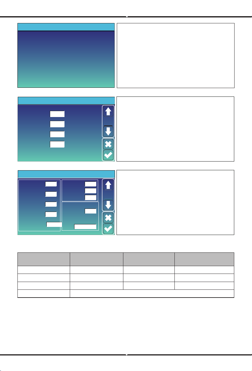
5.4 System Setup Menu
5.5 Basic Setup Menu
System Work Mode
Battery
Setting
Grid Setting
Gen Port
Use
Basic
Setting
System Setup
Device Info.
Advanced
Function
Basic
Set
Time Syncs Beep Auto Dim
24-Hour
Basic Setting
Year Month Day
Hour Minute
Lock out all changesFactory Reset
2019 03
09 15
17
Factory Reset: Reset all parameters of the inverter.
Lock out all changes: Enable this menu for setting
parameters that require locking and cannot be set up.
Before performing a successful factory reset and locking
the systems, to keep all changes you need to type in a
password to enable the setting.
The password for factory settings is 9999 and for lock
out is 7777.
This is System Setup page.
PassWord
DELX--X--X--X
1 2 3
4 5 6
7 8 9
CANCEL 0 OK
Factory Reset Password: 9999
Lock out all changes Password: 7777
System selfchek: Aer ticking this item,
it needs input the password.
The default password is 1234

5.6 Battery Setup Menu
Batt Mode
Lithium
Use Batt V
Battery Setting
Activate Battery
Max A Charge
Batt Capacity
Max A Discharge 40A
40A
400Ah
Batt
Mode
Use Batt %
No Batt
Battery capacity: it tells hybrid inverter to know
your battery bank size.
Use Batt V: Use Battery Voltage for all the settings (V).
Use Batt %: Use Battery SOC for all the settings (%).
Max. A charge/discharge: Max battery charge/discharge
current(0-120A for 5KW model, 0-135A for 6KW model,
0-190A for 7.6/8KW model).
For AGM and Flooded, we recommend Ah battery
size x 20%= Charge/Discharge amps.
. For Lithium, we recommend Ah battery size x 50% =
Charge/Discharge amps.
. For Gel, follow manufacturer' s instructions.
No Batt: tick this item if no battery is connected
to the system.
Active battery: This feature will help recover a
battery that is over discharged by slowly charging
from the solar array or grid.
Grid ChargeGen Charge
Grid SignalGen Signal
Gen Force
Battery Setting
Start
A
30% 30%
40A
40A
Batt
Set2
①
②
③
This is Battery Setup page.
Start =30%: Percent S.O.C at 30% system will AutoStart a
connected generator to charge the battery bank.
A = 40A: Charge rate of 40A from the attached
generator in Amps.
Gen Charge: uses the gen input of the system to charge
battery bank from an attached generator.
Gen Signal: Normally open relay that closes when the
Gen Start signal state is active.
Gen Force: When the generator is connected, it is forced
to start the generator without meeting other conditions.
①③
Start =30%: No use,Just for customization.
A = 40A: It indicates the Current that the
Grid charges the Battery.
Grid Charge: It indicates that the grid charges
the battery.
Grid Signal: Disable.
This is Grid Charge, you need select.
②
07/08/2021 11:11:10 Thu
76%
2.00
KW
-1.39
KW
0.00
KW
KW
0 7
0 5
0 5
0 5
ON
Signal
on
2.00
This page tells the PV and diesel generator
power the load and battery.
There are 3 stages of charging the Battery .
①
②
This is for professional installers, you can keep it
if you do not know.
Shutdown 20%: The inverter will shutdown if the SOC
below this value.
Low Batt 35%: The inverter will alarm if the SOC
below this value.
Restart 50%: Battery SOC at 50% AC output will resume.
③
Float V 53.6V 20%
35%
50%
-5
Absorption V
57.6V
Equalization V
57.6V
Equalization Days
Shutdown
Low Batt
Restart
TEMPCO(mV/C/Cell)
Batt Resistance
30 days
Equalization Hours
3.0 hours
25mOhms
Battery Setting
Set3
Batt
①
②
③
Recommended battery settings
Battery Type
AGM (or PCC)
Absorption Stage
14.2v (57.6v) 13.4v (53.6v)
Float Stage
Torque value
(every 30 days 3hr )
14.2v(57.6v)
Gel 14.1v (56.4v) 13.5v (54.0v)
Wet 14.7v (59.0v) 13.7v (55.0v) 14.7v(59.0v)
Lithium Follow its BMS voltage parameters
Lithium Mode
Shutdown
Low Batt
Restart
40%
20%
10%
00
Battery Setting
Set3
Batt
Lithium Mode: This is BMS protocol.Please reference
the document(Approved Battery).
Shutdown 10%: It indicates the inverter will shutdown
if the SOC below this value.
Low Batt 20%: It indicates the inverter will alarm if the
SOC below this value.
Restart 40%: Battery voltage at 40% AC output will
resume.
This page tells generator output voltage, frequency, power.
And, how much energy is used from generator.
Power: 1392W
L1: 228V
Freq:50.0Hz
Today=0.0 KWH
Total =2.20 KWH
Generator

5.7 System Work Mode Setup Menu
Zero Export To Load
Max Solar Power
Zero Export To CT
Max Sell Power
Energy pattern
BattFirst LoadFirst
System Work Mode
Solar Sell
Solar Sell
8000
8000
Power
8000
Zero-export Power
20
Selling First
Work
Mode1
Grid Peak Shaving
Work Mode
Selling First: This Mode allows hybrid inverter to sell
back any excess power produced by the solar panels to
the grid. If time of use is active, the battery energy also
can be sold into grid.
The PV energy will be used to power the load and charge
the battery and then excess energy will flow to grid.
Power source priority for the load is as follows:
1. Solar Panels.
2. Grid.
3. Batteries (until programable % discharge is reached).
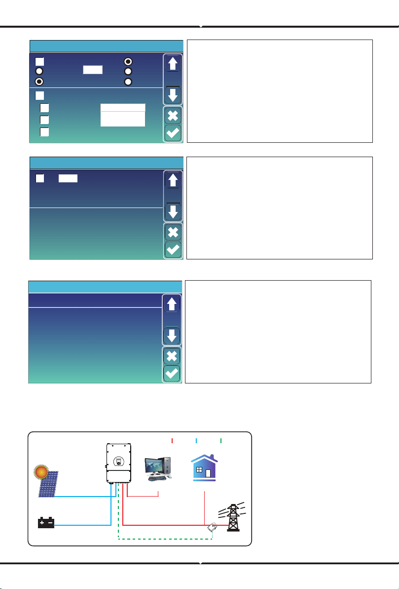
Zero Export To Load: Hybrid inverter will only provide power to the backup load connected. The hybrid
inverter will neither provide power to the home load nor sell power to grid. The built-in CT will detect
power flowing back to the grid and will reduce the power of the inverter only to supply the local load and
charge the battery.
Zero Export To CT: Hybrid inverter will not only provide power to the backup load connected but also give
power to the home load connected. If PV power and battery power is insucient, it will take grid energy
as supplement. The hybrid inverter will not sell power to grid. In this mode, a CT is needed. The installation
method of the CT please refer to chapter 3.6 CT Connection. The external CT will detect power flowing back
to the grid and will reduce the power of the inverter only to supply the local load, charge battery and home
load.
GridBackup Load On-Grid Home Load
Battery
Solar
CT
GridBackup Load On-Grid Home Load
Battery
Solar
Time of use: it is used to program when to use grid or
generator to charge the battery, and when to discharge
the battery to power the load. Only tick "Time Of Use"
then the follow items (Grid, charge, time, power etc.)
will take eect.
Note: when in selling first mode and click time of use,
the battery power can be sold into grid.
Grid charge: utilize grid to charge the battery in a time
period.
Gen charge:
utilize diesel generator to charge the battery
in a time period.
Time: real time, range of 01:00-24:00.
Power: Max. discharge power of battery allowed.
Batt(V or SOC %): battery SOC % or voltage at when the
action is to happen.
Time Of Use
Time
System Work Mode
Batt
Grid
Charge
Gen
01:00
05:00
09:00
13:00
17:00
21:00
5:00
9:00
13:00
17:00
21:00
01:00
Power
8000
8000
8000
8000
8000
8000
49.0V
50.2V
50.9V
51.4V
47.1V
49.0V
Work
Mode2
During 01:00-05:00, when battery SOC is lower than 80%, it will
use grid to charge the battery until battery SOC reaches 80%.
During 05:00-08:00 and 08:00-10:00, when battery SOC is higher
than 40%, hybrid inverter will discharge the battery until the SOC
reaches 40%.
During 10:00-15:00, when battery SOC is higher than 80%, hybrid
inverter will discharge the battery until the SOC reaches 80%.
During 15:00-18:00, when battery SOC is higher than 40%, hybrid
inverter will discharge the battery until the SOC reaches 40%.
During 18:00-01:00, when battery SOC is higher than 35%, hybrid
inverter will discharge the battery until the SOC reaches 35%.
Time Of Use
Time
System Work Mode
Batt
Grid
Charge
Gen
01:00
05:00
08:00
10:00
15:00
18:00
5:00
8:00
10:00
15:00
18:00
01:00
Power
8000
8000
8000
8000
8000
8000
80%
40%
40%
80%
40%
35%
Work
Mode2
For example:
Solar Sell:
“Solar sell” is for Zero export to load or Zero export to CT: when this item is active, the surplus
energy can be sold back to grid. When it is active, PV Power source priority usage is as follows: load
consumption and charge battery and feed into grid.
Max. sell power: Allowed the maximum output power to flow to grid.
Zero-export Power:
for zero-export mode, it tells the grid output power. Recommend to set it as 20-100W
to ensure the hybrid inverter won' t feed power to grid.
Energy Pattern:
PV Power source priority.
Batt First:
PV power is firstly used to charge the battery and then used to power the load. If PV power is
insucient, grid will make supplement for battery and load simultaneously.
Load First:
PV power is firstly used to power the load and then used to charge the battery. If PV power is
insucient, grid will make supplement for battery and load simultaneously.
Max Solar Power:
allowed the maximum DC input power.
Grid Peak-shaving:
when it is active, grid output power will be limited within the set value. If the load
power exceeds the allowed value, it will take PV energy and battery as supplement. If still can’t meet the
load requirement, grid power will increase to meet the load needs.

5.8 Grid Setup Menu
FW: this series inverter is able to adjust inverter output
power according to grid frequency.
Droop f: percentage of nominal power per Hz
For example, “Start freq f>50.2Hz, Stop freq f<50.2,
Droop f=40%PE/Hz” when the grid frequency reaches
50.2Hz, the inverter will decrease its active power at
Droop f of 40%. And then when grid system frequency
is less than 50.2Hz, the inverter will stop decreasing
output power.
For the detailed setup values, please follow the local
grid code.
Grid Setting/F(W)
F(W)
Start freq f
Over frequency
50.20Hz
Start delay f
0.00s
Stop freq f 50.20Hz
Droop f
40
%PE/Hz
Stop delay f
0.00s
Start freq f
Under frequency
49.80Hz
Start delay f
Stop freq f 49.80Hz
Droop f 40%PE/Hz
Stop delay f
0.00s
0.00s
Grid
Set4
Grid Mode: General Standard、UL1741 & IEEE1547、
CPUC RULE21、SRD-UL-1741、CEI 0-21、EN50549_CZ、
Australia A、Australia B、Australia C、NewZealand、
VDE4105、OVE_Directive_R25、EN50549_CZ_PPDS_L16A、
NRS097、G98、G99.
Please follow the local grid code and then choose the
corresponding grid standard.
0/15
Grid Setting
Grid Mode
Grid
Set1
Grid Frequency
50HZ
60HZ
General Standard
Reconnection Time PF
60s
Grid Setting/Connect
Low frequency
Normal connect
48.00Hz
Low voltage
185.0V
High frequency 51.50Hz
Normal Ramp rate 60s
Reconnect Ramp rate 60s
High voltage
265.0V
Low frequency
Reconnect aer trip
Low voltage
High frequency
51.30Hz
High voltage
263.0V
48.20Hz
187.0 V
Grid
Set2
Normal connect: The allowed grid voltage/frequency
range when the inverter first time connect to the grid.
Normal Ramp rate: It is the startup power ramp.
Reconnect aer trip: The allowed grid voltage
/frequency range for the inverter connects the grid
aer the inverter trip from the grid.
Reconnect Ramp rate:It is the reconnection power ramp.
Reconnection time: The waiting time period for the
inverter connects the grid again.
PF: Power factor which is used to adjust inverter
reactive power.
Over voltage U>(10 min. running mean)
Grid Setting/IP Protection
260.0V
Set3
Grid
--
HV1
265.0V
0.10s
--
HV2
265.0V
0.10s
HV3
--
LV1
185.0V
0.10s
--
LV2
185.0V
0.10s
185.0V
LV3
--
HF1
51.50Hz
0.10s
--
HF2
0.10s
HF3
--
LF1
48.00Hz
0.10s
--
LF2
0.10s
LF3
①
②
① ②
0.10s—Trip time.
LV1: Level 1 undervoltage protection point;
LV2: Level 2 undervoltage protection point;
LV3: Level 3 undervoltage protection point.
HV1: Level 1 overvoltage protection point;
HV2: Level 2 overvoltage protection point;
HV3: Level 3 overvoltage protection point.
HF1: Level 1 over frequency protection point;
HF2: Level 2 over frequency protection point;
HF3: Level 3 over frequency protection point.
LF1: Level 1 under frequency protection point;
LF2: Level 2 under frequency protection point;
LF3: Level 3 under frequency protection point.
265.0V
51.50Hz
51.50Hz
48.00Hz
48.00Hz
INV Output Voltage
220V
240V
230V
200V
Grid Type
120/240V Split Phase
120/208V 3 Phase
Single Phase
1.000

Grid Setting/V(W) V(Q)
V(W) V(Q)
V1
109.0%
P2
V2
110.0%
P3
P4
V3
111.0%
V4
111.0%
P1
100%
20%
20%
20%
Lock-in/Pn Lock-out/Pn
V1
90.0%
Q2
V2
95.7%
Q3
Q4
V3
104.3%
V4
112.2%
Q1
44%
0%
0%
-60%
Grid
Set5
V(W): It is used to adjust the inverter active power
according to the set grid voltage.
V(Q): It is used to adjust the inverter reactive power
according to the set grid voltage.
This function is used to adjust inverter output power
(active power and reactive power) when grid voltage
changes.
For example: V2=110%, P2=20%. When the grid voltage reaches the 110% times of rated grid voltage,
inverter output power will reduce its active output power to 20% rated power.
For example: V1=90%, Q1=44%. When the grid voltage reaches the 90% times of rated grid voltage,
inverter output power will output 44% reactive output power.
For the detailed setup values, please follow the local grid code.
Grid Setting/P(Q) P(F)
P(Q) P(PF)
P1
0%
Q2
P2
0%
Q3
Q4
P3
0%
P4
0%
Q1
0%
0%
0%
0%
P1
0%
PF2P2
0%
PF3
PF4
P3
0%
P4
0%
PF1
-2.400
0.000
0.000
6.000
Grid
Set6
P(Q): It is used to adjust the inverter reactive power
according to the set active power.
P(PF): It is used to adjust the inverter PF according
to the set active power.
For the detailed setup values, please follow the local
grid code.
Lock-in/Pn Lock-out/Pn
Grid Setting/LVRT
L/HVR
HV1
115%
LV1
50%
Grid
Set7
Reserved: This function is reserved.It is not
recommended.
5%
20%
50%
50%
Lock-in/Pn 5%: When the inverter active power is less
than 5% rated power, the VQ mode will not take eect.
Lock-out/Pn 20%: If the inverter active power is
increasing from 5% to 20% rated power, the VQ mode
will take eect again.
Lock-in/Pn 50%: When the inverter output active power
is less then 50% rated power, it won't enter the P(PF)
mode.
Lock-out/Pn 50%: Lock-out/Pn 50%: When the inverter
output active power is higher then 50% rated power, it
will enter the P(PF) mode.
Note : only when the grid voltage is equal to or higher
than 1.05times of rated grid voltage, then the P(PF)
mode will take eect.

Solar Arc Fault ON:
This is only for US.
System selfcheck:
Disable. this is only for factory.
Gen Peak-shaving:
Enable When the power of the
generator exceeds the rated value of it, the inverter will
provide the redundant part to ensure that the generator
will not overload.
DRM:
For AS4777 standard
Backup Delay: (
0-300)S adjustable
BMS_Err_Stop:
When it is active, if the battery BMS failed
to communicate with inverter, the inverter will stop
working and report fault.
Signal ISLAND MODE:
when "signal island mode" is
checked and the inverter connects the grid, the ATS port
voltage will be 0. When "signal island mode" is checked
and the inverter disconnected from the grid, the ATS port
voltage will output 230Vac voltage. With this feature and
outside NO type relay, it can realize N and PE disconnection
or bond.
More details, please refer to le side picture.
Generator input rated power: allowed Max. power from diesel
generator.
GEN connect to grid input: connect the diesel generator to the
grid input port.
Smart Load Output: This mode utilizes the Gen input connection
as an output which only receives power when the battery SOC
and PV power is above a user programmable threshold.
e.g. Power=500W, ON: 100%, OFF=95%: When the PV power
exceeds 500W, and battery bank SOC reaches 100%, Smart Load
Port will switch on automatically and power the load connected.
When the battery bank SOC < 95% or PV power < 500w, the
Smart Load Port will switch o automatically.
Mode
OFF
ON
Generator Input
SmartLoad Output
Micro Inv Input
On Grid always on
GEN PORT USE
52.00Hz
100%
95%
Power
Rated Power
AC Couple Fre High
500W
8000W
PORT
Set1
Smart Load OFF Batt
• Battery SOC at which the Smart load will switch o.
Smart Load ON Batt
• Battery SOC at which the Smart load will switch on. Also, the PV input power should exceed the setting value (Power)
simultaneously and then the Smart load will switch on.
On Grid always on: When click "on Grid always on" the smart load will switch on when the grid is present.
Micro Inv Input: To use the Generator input port as a micro-inverter on grid inverter input (AC coupled), this feature will
also work with "Grid-Tied" inverters.
*Micro Inv Input OFF: when the battery SOC exceeds setting value, Microinveter or grid-tied inverter will shut down.
*Micro Inv Input ON: when the battery SOC is lower than setting value, Microinveter or grid-tied inverter will start to
work.
AC Couple Fre High: If choosing“Micro Inv input”, as the battery SOC reaches gradually setting value (OFF), During the
process, the microinverter output power will decrease linear. When the battery SOC equals to the setting value (OFF),
the system frequency will become the setting value (AC couple Fre high) and the Microinverter will stop working.
Stop exporting power produced by the microinverter to the grid.
*
Note
: Micro Inv Input OFF and On is valid for some certain FW version only.
*AC couple on load side
: connecting the output of on-grid inverter at the load port of the hybrid inverter. In this
situation, the hybrid inverter will not able to show the load power correctly.
*AC couple on grid side
: this function is reserved.
*Note
: Some firmware versions don’t have this function.
GEN connect to Grid input
AC couple on grid side
AC couple on load side
*MI export to grid cutso:
coil
external relay
open
contact
L N ATS
load port
Inverter
shell
Ground cable
230V
Solar Arc Fault ON
Clear Arc_Fault
System selfcheck
BMS_Err_Stop
0ms
2000:1
Backup Delay
Advanced Function
Func
Set1
DRM
Gen peak-shaving
CEI 0-21 Report
CT Ratio
Signal ISLAND MODE
5.9 Generator Port Use Setup Menu
5.10 Advanced Function Setup Menu
Ex_Meter For CT:
when in Three phase system with CHNT
Three phase energy meter (DTSU666), click corresponding
phase where hybrid inverter is connected. e.g. when the
hybrid inverter output connects to A phase, please click A
Phase.
6. Mode
5.11 Device Info Setup Menu
HMI: LCD version
Volt
1
2
3
50.38V 19.70A 30.6C 52.0% 26.0Ah 0.0V 0.0A 0|0|0
50.33V 19.10A 31.0C 51.0% 25.5Ah 53.2V 25.0A 0|0|0
50.30V 16.90A 30.2C 12.0% 6.0Ah 53.2V 25.0A 0|0|0
4
5
0.00V 0.00A 0.0C 0.0% 0.0Ah 0.0V 0.0A 0|0|0
0.00V 0.00A 0.0C 0.0% 0.0Ah 0.0V 0.0A 0|0|0
0.00V 0.00A 0.0C 0.0% 0.0Ah 0.0V 0.0A 0|0|0
0.00V 0.00A 0.0C 0.0% 0.0Ah 0.0V 0.0A 0|0|0
0.00V 0.00A 0.0C 0.0% 0.0Ah 0.0V 0.0A 0|0|0
0.00V 0.00A 0.0C 0.0% 0.0Ah 0.0V 0.0A 0|0|0
0.00V 0.00A 0.0C 0.0% 0.0Ah 0.0V 0.0A 0|0|0
0.00V 0.00A 0.0C 0.0% 0.0Ah 0.0V 0.0A 0|0|0
0.00V 0.00A 0.0C 0.0% 0.0Ah 0.0V 0.0A 0|0|0
0.00V 0.00A 0.0C 0.0% 0.0Ah 0.0V 0.0A 0|0|0
0.00V 0.00A 0.0C 0.0% 0.0Ah 0.0V 0.0A 0|0|0
0.00V 0.00A 0.0C 0.0% 0.0Ah 0.0V 0.0A 0|0|0
6
7
8
9
10
11
12
13
14
15
Curr
Volt Curr
Temp SOC Energy
Charge
Fault
Sum
Data
Details
Data
Li-BMS
Volt
1
2
3
50.38V 19.70A 30.6C 52.0% 26.0Ah 0.0V 0.0A 0|0|0
50.33V 19.10A 31.0C 51.0% 25.5Ah 53.2V 25.0A 0|0|0
50.30V 16.90A 30.2C 12.0% 6.0Ah 53.2V 25.0A 0|0|0
4
5
0.00V 0.00A 0.0C 0.0% 0.0Ah 0.0V 0.0A 0|0|0
0.00V 0.00A 0.0C 0.0% 0.0Ah 0.0V 0.0A 0|0|0
0.00V 0.00A 0.0C 0.0% 0.0Ah 0.0V 0.0A 0|0|0
0.00V 0.00A 0.0C 0.0% 0.0Ah 0.0V 0.0A 0|0|0
0.00V 0.00A 0.0C 0.0% 0.0Ah 0.0V 0.0A 0|0|0
0.00V 0.00A 0.0C 0.0% 0.0Ah 0.0V 0.0A 0|0|0
0.00V 0.00A 0.0C 0.0% 0.0Ah 0.0V 0.0A 0|0|0
0.00V 0.00A 0.0C 0.0% 0.0Ah 0.0V 0.0A 0|0|0
0.00V 0.00A 0.0C 0.0% 0.0Ah 0.0V 0.0A 0|0|0
0.00V 0.00A 0.0C 0.0% 0.0Ah 0.0V 0.0A 0|0|0
0.00V 0.00A 0.0C 0.0% 0.0Ah 0.0V 0.0A 0|0|0
0.00V 0.00A 0.0C 0.0% 0.0Ah 0.0V 0.0A 0|0|0
6
7
8
9
10
11
12
13
14
15
Curr
Volt Curr
Temp SOC Energy
Charge
Fault
Sum
Data
Details
Data
Li-BMSDevice Info.
Inverter ID: 1601012001 Flash
MAIN:Ver 0-5213-0717
HMI: Ver0302
Alarms Code
F64 Heatsink_HighTemp_Fault
F64 Heatsink_HighTemp_Fault
F64 Heatsink_HighTemp_Fault
2019-03-11 15:56
2019-03-08 10:46
2019-03-08 10:45
Occurred
Device
Info
Mode I:Basic
MAIN: Control board FW version
This page show Inverter ID, Inverter
version and alarm codes.
Grid
Backup Load On-Grid Home Load
CT
Battery
Solar
AC cable DC cable
COM cable
Parallel
Master
Slave
Ex_Meter For CT Meter Select
C Phase
00
CHNT-3P
Modbus SN
Advanced Function
Paral.
Set3
A Phase 0/4
B Phase
B Phase
A Phase
C Phase
CHNT-1P
Eastron-3P
Eastron-1P
ATS
ON
Advanced Function
Func
Set4
ATS:
It is related with ATS port voltage. it is better in
"uncheck" position.
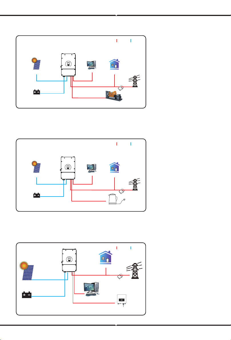
Grid
Backup Load On-Grid Home Load
Battery
Solar
CT
AC cable DC cable
Generator
Mode II: With Generator
Grid
Backup Load On-Grid Home Load
Battery
Solar
CT
AC cable DC cable
Smart Load
Mode III: With Smart-Load
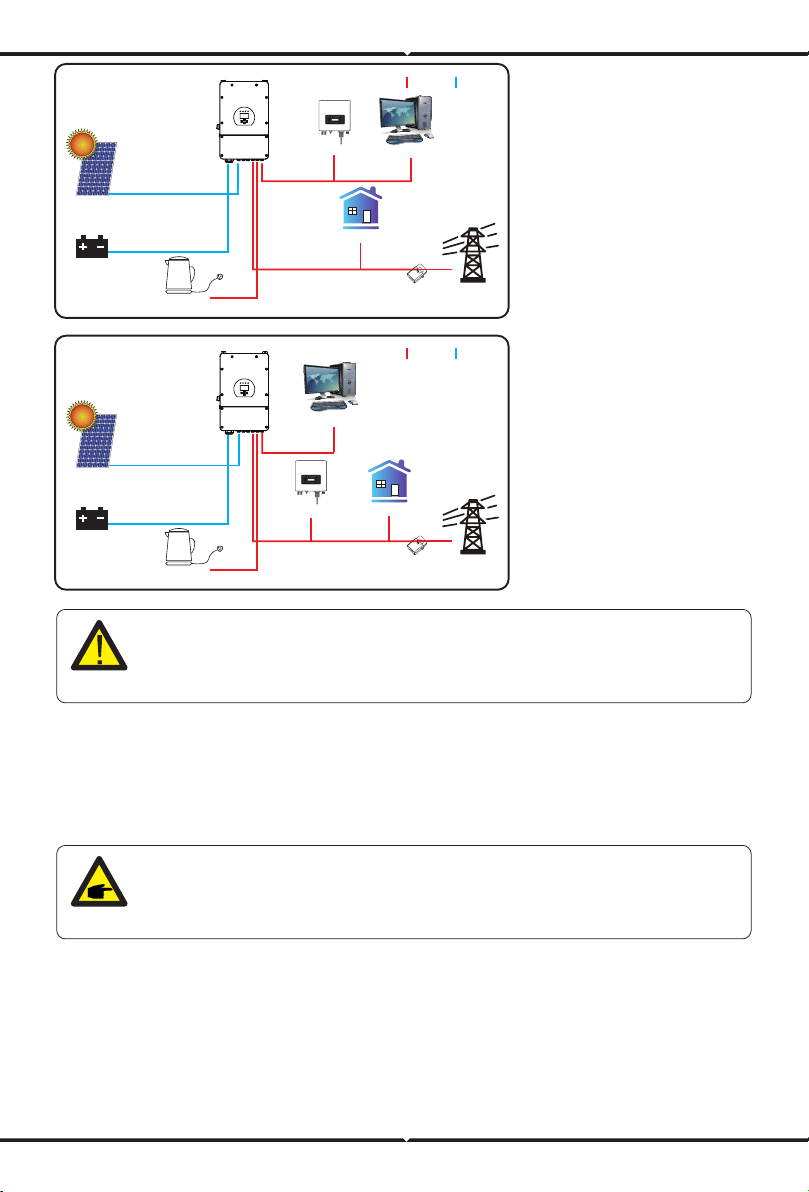
On-Gen+AC couple
AC cable DC cable
CT
Battery
Solar
Grid
Backup Load
On-Grid Home Load
On-Grid Inverter
Mode IV: AC Couple
7. Fault information and processing
The energy storage inverter is designed according to the grid-connected operation standard
and meets the safety requirements and electromagnetic compatibility requirements. Before
leaving the factory, the inverter undergoes several rigorous tests to ensure that the inverter
can operate reliably.
1. Inverter serial number;
2. Distributor or service center of the inverter ;
3. On-grid power generation date;
4. The problem description (including the fault code and indicator status displayed on the LCD)
is as detailed as possible.
5. Your contact information.In order to give you a clearer understanding of the inverter's fault
information, we will list all possible fault codes and their descriptions when the inverter is not
working properly.
The 1st priority power of the system is always the PV power, then 2nd and
3rd priority power will be the battery bank or grid according to the settings.
The last power backup will be the Generator if it is available.
If any of the fault messages listed in Table 7-1 appear on your inverter and the
fault has not been removed aer restarting, please contact your local dealer or
service center. You need to have the following information ready.
On-Load+AC couple
AC cable DC cable
CT
Battery
Solar
Grid
Backup Load
On-Grid Home Load
On-Grid Inverter
Smart Load
On-Grid+AC couple
AC cable DC cable
CT
Battery
Solar
Grid
Backup Load
On-Grid Home Load
On-Grid Inverter
Smart Load

Error code Description Solutions
F13 Working mode change
F18
AC over current fault
of hardware
F20
DC over current fault of
the hardware
F23
F22
AC leakage current is
transient over current
Tz_EmergStop_Fault
F24
DC insulation impedance
failure
F26
The DC busbar is
unbalanced
F29 Parallel CANBus fault
1. When the grid type and frequency changed it will report F13;
2. When the battery mode was changed to “No battery” mode,
it will report F13;
3. For some old FW version, it will report F13 when the system
work mode changed;
4, Generally, it will disappear automatically when shows F13;
5. If still same, and turn o the DC switch and AC switch and
wait for one minute and then turn on the DC/AC switch;
6. Seek help from us, if can not go back to normal state.
F08 GFDI _Relay_Failure
1. When inverter is in Split phase(120/240Vac) or three-phase
system (120/208Vac) system, the backup load port N line
needs to connect ground;
2. If the fault still exists, please contact us for help.
AC side over current fault
1. Please check whether the backup load power and common
load power are within the range;
2. Restart and check whether it is in normal;
3. Seek help from us, if can not go back to normal state.
DC side over current fault
1. Check PV module connect and battery connect;
2. When in the o-grid mode, the inverter startup with big power
load, it may report F20. Please reduce the load power connected;
3. Turn o the DC switch and AC switch and then wait one
minute,then turn on the DC/AC switch again;
4. Seek help from us, if can not go back to normal state.
Leakage current fault
1. Check PV side cable ground connection.
2. Restart the system 2~3 times.
3. If the fault still exists, please contact us for help.
Please contact your installer for help.
PV isolation resistance is too low
1. Check the connection of PV panels and inverter is firmly and
correctly;
2. Check whether the PE cable of inverter is connected to ground;
3. Seek help from us, if can not go back to normal state.
1. Please wait for a while and check whether it is normal;
2. When the hybrid in split phase mode, and the load of L1 and
load of L2 is big dierent, it will report the F26.
3. Restart the system 2~3 times.
4. Seek help from us, if can not go back to normal state.
1. When in parallel mode, check the parallel communication cable
connection and hybrid inverter communication address setting;
2. During the parallel system startup period, inverters will report F29.
when all inverters are in ON status, it will disappear automatically;
3. If the fault still exists, please contact us for help.

Error code Description Solutions
F35 No AC grid
No Utility
1. Please confirm grid is lost or not;
2. Check the grid connection is good or not;
3. Check the switch between inverter and grid is on or not;
4. Seek help from us, if can not go back to normal state.
F41 Parallel system stop
1. Check the hybrid inverter working status. If there's 1 pcs
hybrid inverter is in OFF status, the other hybrid inverters
may report F41 fault in parallel system.
2. If the fault still exists, please contact us for help.
F42 AC line low voltage
F47 AC over frequency
Grid voltage fault
1. Check the AC voltage is in the range of standard voltage in
specification;
2. Check whether grid AC cables are firmly and correctly
connected;
3. Seek help from us, if can not go back to normal state.
Grid frequency out of range
1. Check the frequency is in the range of specification or not;
2. Check whether AC cables are firmly and correctly connected;
3. Seek help from us, if can not go back to normal state.
F48 AC lower frequency
Grid frequency out of range
1. Check the frequency is in the range of specification or not;
2. Check whether AC cables are firmly and correctly connected;
3. Seek help from us, if can not go back to normal state.
F56
DC busbar voltage is
too low
Battery voltage low
1. Check whether battery voltage is too low;
2. If the battery voltage is too low, using PV or grid to charge the
battery;
3. Seek help from us, if can not go back to normal state.
F58 BMS communication fault
1. it tells the communication between hybrid inverter and battery
BMS disconnected when"BMS_Err-Stop" is active;
2. if don’t want to see this happen, you can disable
"BMS_Err-Stop" item on the LCD;
3. If the fault still exists, please contact us for help.
F63 ARC fault
F64
Heat sink high temperature
failure
1. ARC fault detection is only for US market;
2. Check PV module cable connection and clear the fault;
3. Seek help from us, if can not go back to normal state.
Heat sink temperature is too high
1. Check whether the work environment temperature is too high;
2. Turn o the inverter for 10mins and restart;
3. Seek help from us, if can not go back to normal state.
F34 AC Overcurrent fault
1. Check the backup load connected, make sure it is in allowed
power range;
2. If the fault still exists, please contact us for help.
Chart 7-1 Fault information

8.Limitation of Liability
In addition to the product warranty described above, the state and local laws and regulations
provide financial compensation for the product's power connection (including violation of implied
terms and warranties). The company hereby declares that the terms and conditions of the
product and the policy cannot and can only legally exclude all liability within a limited scope.
Under the guidance of our company, customers return our products so that our company can
provide service of maintenance or replacement of products of the same value. Customers need to
pay the necessary freight and other related costs. Any replacement or repair of the product will
cover the remaining warranty period of the product. If any part of the product or product is
replaced by the company itself during the warranty period, all rights and interests of the
replacement product or component belong to the company.
Factory warranty does not include damage due to the following reasons:
· Damage during transportation of equipment;
· Damage caused by incorrect installation or commissioning;
· Damage caused by failure to comply with operation instructions, installation instructions or
maintenance instructions;
· Damage caused by attempts to modify, alter or repair products;
· Damage caused by incorrect use or operation;
· Damage caused by insucient ventilation of equipment;
· Damage caused by failure to comply with applicable safety standards or regulations;
· Damage caused by natural disasters or force majeure (e.g. floods, lightning, overvoltage, storms,
fires, etc.)
In addition, normal wear or any other failure will not aect the basic operation of the product.
Any external scratches, stains or natural mechanical wear does not represent a defect in the
product.
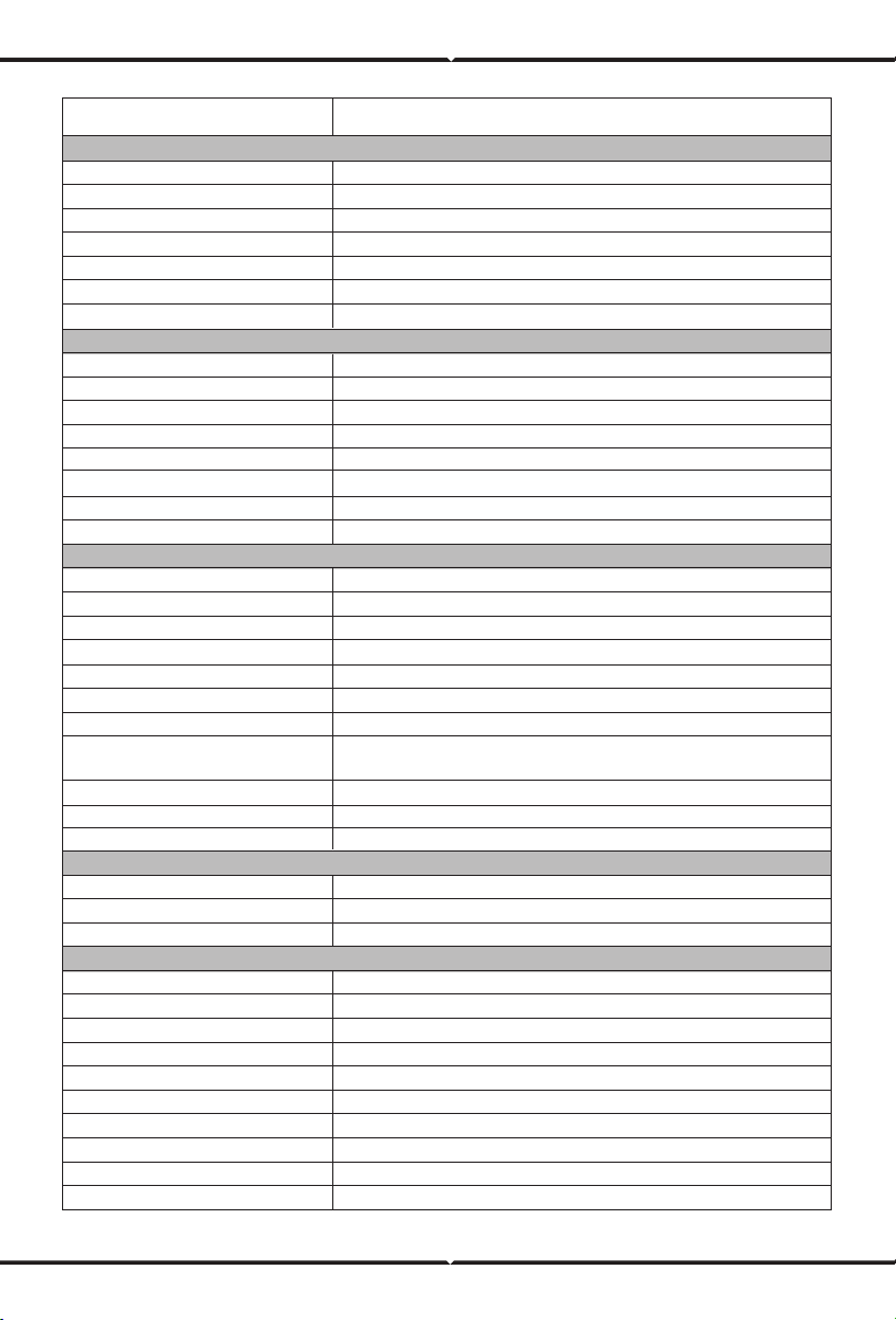
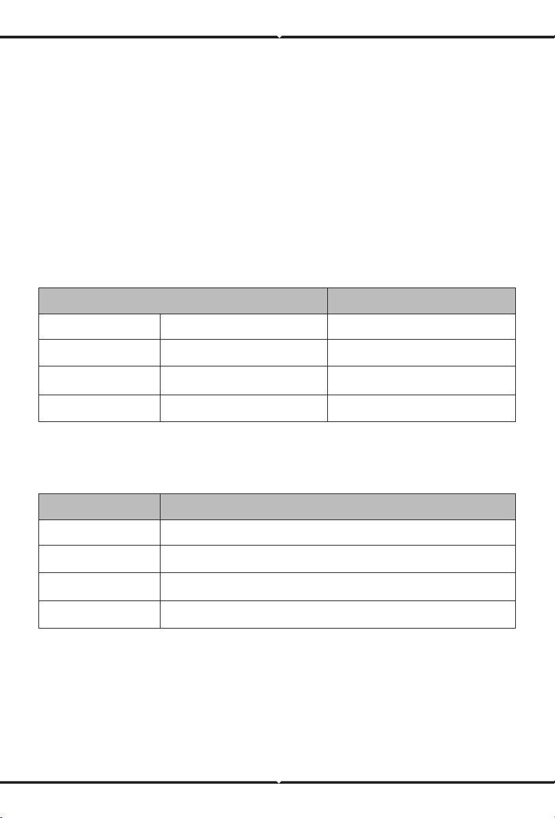
9. Datasheet
Model
Battery Input Date
Charging Strategy for Li-lon Battery
Battery Type
Battery Voltage Range(V)
Max. Charging Current(A)
Max. Discharging Current(A)
Charging Curve
External Temperature Sensor
PV String Input Data
Max. DC Input Power(W)
PV Input Voltage(V)
MPPT Range(V)
Lead-acid or Li-lon
40-60
3 Stages / Equalization
yes
Self-adaption to BMS
370(125~500)
150~425
190
10400
190
Start-up Voltage(V)
PV Input Current(A)
No. of MPPT Trackers
125
44+44
26+26
2
Max. AC Output Power(W)
Peak Power(o grid)
Max. AC Current(A)
Max. Continuous AC Passthrough(A)
0.8 leading to 0.8 laggingPower Factor
AC Output Rated Current(A)
No. of Strings Per MPPT Tracker
AC Output Data
2 times of rated power, 10 S
50
2
8000
8800
Rated AC Output and UPS Power(W)
50 / 60Hz; 220/230Vac (single phase)
Split phase; 2 / 3 phase; Single Phase
Output Frequency and Voltage
Grid Type
<3% (of nominal power)
97.60%
Total Harmonic Distortion (THD)
Eciency
Max. Eciency
97.00%Euro Eciency
>99%
MPPT Eciency
Protection
Integrated
Integrated
Anti-islanding Protection
PV Input Lightning Protection
PV Arc Fault Detection
Integrated
Integrated
PV String Input Reverse Polarity Protection
IntegratedInsulation Resistor Detection
DC Type II / AC Type IISurge Protection
IntegratedOutput Shorted Protection
Residual Current Monitoring Unit Integrated
IntegratedOutput Over Current Protection
DC Type II / AC Type IIIOver Voltage Category
<0.5% lnDC current injection
Max.PV Isc(A)
36.4/34.8
40/38.3
SUN-8K-SG01LP1-EU

SUN-8K-SG01LP1-EU
Model
Certifications and Standards
Grid Regulation
EMC / Safety Regulation
General Data
Protection Degree
Operating Temperature Range(℃)
Cooling
Noise(dB)
Communication with BMS
Weight(kg)
Size(mm)
Installation Style
Warranty
-40~60℃, >45℃ Derating
<30 dB
Smart cooling
RS485; CAN
32
420W×670H×233D
IP65
5 years
Wall-mounted
VDE4105,IEC61727/62116,VDE0126,AS4777.2,CEI 0 21,EN50549-1,
G98,G99,C10-11,UNE217002,NBR16149/NBR16150
IEC/EN 62109-1,IEC/EN 62109-2,IEC/EN 61000-6-1,
IEC/EN 61000-6-2,IEC/EN 61000-6-3,IEC/EN 61000-6-4
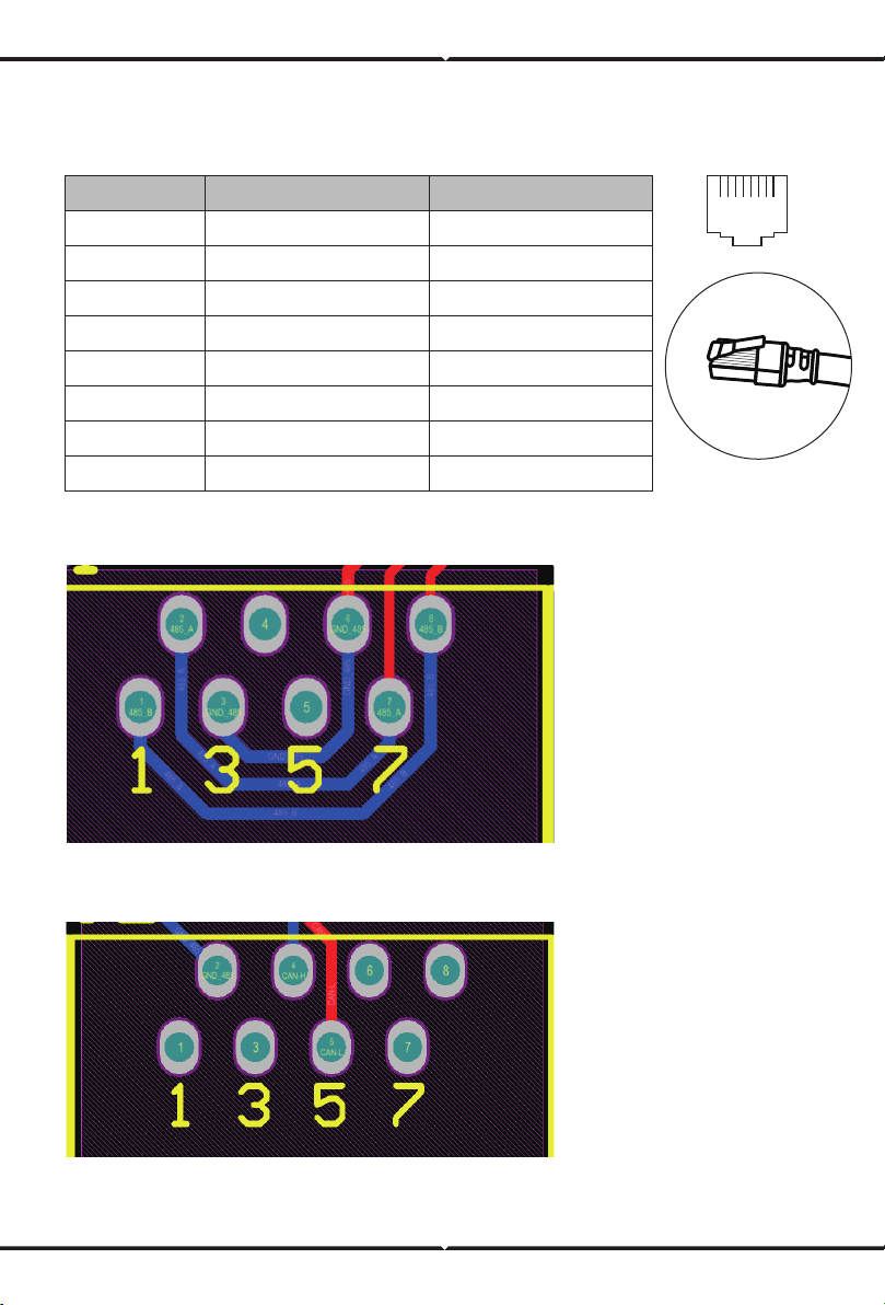
Definition of RJ45 Port Pin for BMS
10. Appendix I
1
No.
RS485
RS485 Pin CAN Pin
--
2 Meter_CON GND
3 GND --
4 CANH
5 CANL
6 GND --
7 RS485A --
8 RS485B --
12345678
RS485 Port
CAN Port
87654321
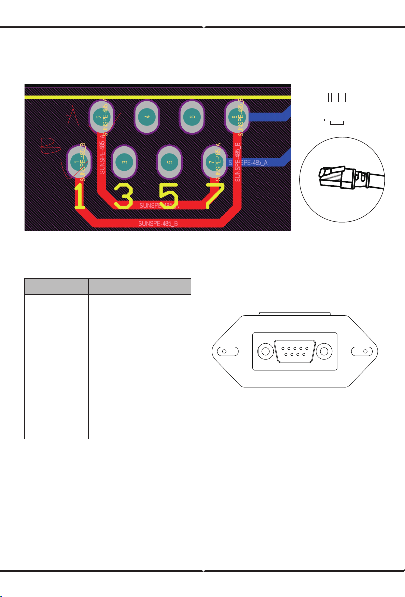
Meter_CON port
This port is used to connect the energy meter.
12345678
87654321
RS232
WIFI/RS232
12345
6789
This RS232 port is used to connect the wifi datalogger
Note: some hardware versions hybrid inverter don't support conencting the energy meter
1
No.
D-GND
WIFI/RS232
2
3
4
5
6
TX
7
12Vdc
8
RX
9
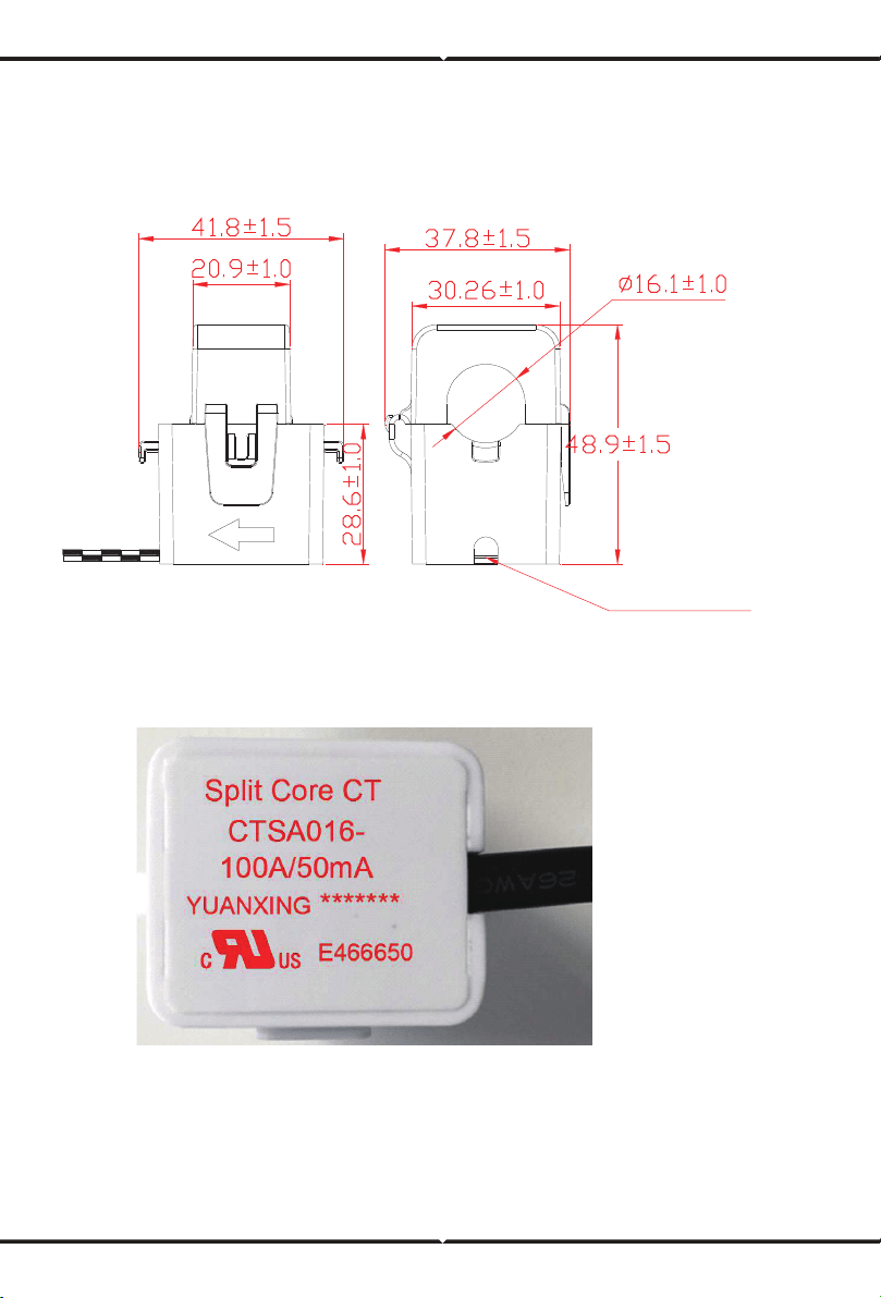
1. Split Core Current Transformer (CT) dimension: (mm)
2. Secondary output cable length is 4m.
11. Appendix II
Lead Outside