
Owner's Manual
CRI FTSMIIN°
20.0 HP, 42" Mower
Electric Start
6 Speed Transaxle
Model No.
917.273850
[_] his product has a mowemission engine which operates
differentmy from previousmy buimt engines. Before you start the
engine, read and understand this Owner's Manuak
Read and follow aH Safety
Rules and Instructions before
operating this equipment.
For answers to your questions
about this product, Call:
1_800°659-5917
Sears Craftsman Help Line
5 am =5 pm, Men =Sat
Sears, Roebuck and Co., Hoffman Estates, IL 60179 U.S.A.
Visit our Craftsman website:www.sears.com/craftsman
Warranty.................................................2
SafetyRules...........................................3
ProductSpecifications............................6
Assembly/Pre-Operation........................8
Operation..............................................11
MaintenanceSchedule.........................17
Maintenance.........................................17
Service andAdjustments......................21
Storage.................................................27
Troubleshooting....................................28
Repair Parts..........................................32
Sears Service.........................BackCover
LIMITEDWARRANTYON CRAFTSMANRIDINGEQUIPMENT
Fortwo (2)years from the date of purchase,if this CraftsmanRiding Equipmentis
maintained,lubricatedand tuned up accordingto the instructionsin the owner'smanual,
Searswill repairor replacefree of chargeany partsthat are foundto be defectivein
materialor workmanshipaccordingto the guidelinesof coveragelisted below.Searswill
also providefree laborfor these applicablewarrantedpartsfor the two full years.During
the first 30 days of purchase,there will be no chargesto servicethe productat your
homefor issuescoveredby this warranty.(See exclusionsbelow). Foryour conve-
nience, IN HOMEwarrantyservicewill still be availableafterthe first 30 days of pur-
chase, buta trip chargewill apply.Thischargewill be waived if the Craftsmanproduct is
droppedoff at an authorizedSears location.For the nearestauthorizedSears location,
pleasecall 1-800-4-MY-HOME@.This warrantyapplies onlywhile this productis within
the UnitedStates.
This Warrantydoes notcover:
Expendableitemswhich becomeworn during normaluse, includingbut not limitedto
blades,spark plugs,air cleaners,belts,and oil filters.
StandardMaintenanceServicing,oil changes, or tune-ups
Tire replacementor repaircausedby puncturesfrom outsideobjects,such as nails,
thorns,stumps,or glass.
Repairs necessarybecauseof operatorabuse, includingbut not limitedto, damage
causedby towingobjectsbeyondthe capabilityof the riding equipment,impacting
objectsthat bendthe frameor crankshaft,or over-speedingthe engine.
Repairs necessarybecauseof operatornegligence,includingbut not limitedto, elec-
trical and mechanicaldamagecausedby improperstorage,failureto use the proper
gradeand amount of engine oil, failureto keepthe deckclear of flammabledebris,
or failureto maintainthe equipmentaccordingto the instructionscontainedin the
owner'smanual.
• Engine (fuel system)cleaningor repairscausedby fuel determinedto be contami-
nated or oxidized(stale). In general,fuel should be used within30 days of its pur-
chase date.
• Normaldeteriorationand wear of the exteriorfinishes,or productlabel replacement.
• Ridingequipmentusedfor commercialor rental purposes.
LIMITEDWARRANTYON BATTERY
For ninety(90) daysfrom date of purchase,if any batteryincludedwith this riding equip-
ment provesdefectivein materialor workmanshipand our testing determinesthe battery
will not holda charge, Searswill replacethe batteryat no charge. Duringthe first 30
daysof purchase,there will be no chargesto replacethe batteryat your HOME. After
the first 30 days,foryour convenience,IN-HOMEwarrantyservicewill still be avail-
ablebut a trip chargewill apply. Thischarge will be waived if the Craftsmanproduct is
droppedoff at an authorizedSears location.For the nearestauthorizedSears location,
pleasecall 1-800-4-MY-HOME@.
This battery warrantyapplies onlywhile this productis within the United States.
This warrantygivesyou specificlegal rights,and you mayalso haveother rights,which
vary,from state to state.
Sears,Roebuckand Co.,Dept.817WA,HoffmanEstates,IL 60179
mMPORTANT:This cutting machineis capableof amputatinghandsandfeet and throw-
ing objects.Failureto observethe followingsafety instructionscould resultin serious
injuryor death.
_WARNING: In orderto preventac-
cidental starting whensetting up, trans-
porting,adjustingor makingrepairs,
alwaysdisconnectspark plugwire and
placewire where it cannotcontactspark
ug.
WARNING: Do notcoast downa hill in
neutral,you may losecontrol of the tractor.
_WARNING: Towonly the attachments
that are recommendedby and complywith
specificationsof the manufacturerof your
tractor.Use commonsense whentowing.
Operateonly at the lowestpossiblespeed
when on a slope. Tooheavy of a load,
while on a slope, is dangerous. Tirescan
losetraction with the groundand cause
,_u to lose control of your tractor.
WARNING: Engine exhaust, some of its
constituents, and certain vehicle compo-
nents contain or emit chemicals known to
the State of California to cause cancer and
birth defects or other reproductive harm.
_WARNING: Battery posts, terminals
and related accessories contain lead and
lead compounds, chemicals known to the
State of California to cause cancer and
birth defects or other reproductive harm.
Wash hands after handling.
L GENERAL OPERATmON
,, Read, understand, and follow all instruc-
tions in the manual and on the machine
before starting.
,_ Only allow responsible adults, who are
familiar with the instructions, to operate
the machine.
,, Clear the area of objects such as rocks,
toys, wire, etc., which could be picked
up and thrown by the blade.
,, Be sure the area is clear of other people
before mowing. Stop machine if anyone
enters the area.
,_ Never carry passengers.
,, Do not mow in reverse unless abso-
lutely necessary. Always look down and
behind before and while backing.
,, Be aware of the mower discharge direc-
tion and do not point it at anyone. Do
not operate the mower without either
the entire grass catcher or the guard in
place.
,, Slow down before turning.
,_ Never leave a running machine unat-
tended. Always turn off blades, set
parking brake, stop engine, and remove
keys before dismounting.
,, Turn off blades when not mowing.
,_ Stop engine before removing grass
catcher or unclogging chute.
,_ Mow only in daylight or good artificial
light.
,_ Do not operate the machine while under
the influence of alcohol or drugs.
,, Watch for traffic when operating near or
crossing roadways.
,, Use extra care when loading or un-
loading the machine into a trailer or
truck.
,_ Data indicates that operators, age 60
years and above, are involved in a large
percentage of riding mower-related in-
juries. These operators should evaluate
their ability to operate the riding mower
safely enough to protect themselves and
others from serious injury.
,, Keep machine free of grass, leaves or
other debris build-up which can touch
hot exhaust / engine parts and burn. Do
not allow the mower deck to plow leaves
or other debris which can cause build-
up to occur. Clean any oil or fuel
spillage before operating or storing the
machine. Allow machine to cool before
storage.
H. SLOPE OPERATION
Slopes are a major factor related to loss-
of-control and tipover accidents, which can
result in severe injury or death. All slopes
require extra caution. If you cannot back
up the slope or if you feel uneasy on it, do
not mow it.
3

DO:
Mow up and down slopes, not across.
Remove obstacles such as rocks, tree
limbs, etc.
Watch for holes, ruts, or bumps. Un-
even terrain could overturn the machine.
Taft grass can hide obstacles.
Use slow speed. Choose a low gear
so that you will not have to stop or shift
while on the slope.
Follow the manufacturer's recommend-
ations for wheel weights or counter-
weights to improve stability.
Use extra care with grass catchers or
other attachments. These can change
the stability of the machine.
Keep all movement on the slopes slow
and gradual Do not make sudden
changes in speed or direction.
Avoid starting or stopping on a slope. If
tires lose traction, disengage the blades
and proceed slowly straight down the
slope.
DO NOT:
Do not turn on slopes unless neces-
sary, and then, turn slowly and gradually
downhill, if possible.
Do not mow near drop-offs, ditches,
or embankments. The mower could
suddenly turn over if a wheel is over
the edge of a cliff or ditch, or if an edge
caves in.
Do not mow on wet grass. Reduced
traction could cause sliding.
Do not try to stabilize the machine by
putting your foot on the ground.
Do not use grass catcher on steep
slopes.
ill. CHILDREN
Tragic accidents can occur if the operator
is not alert to the presence of children.
Children are often attracted to the ma-
chine and the mowing activity. Never as-
sume that children will remain where you
last saw them.
Keep children out of the mowing area
and under the watchful care of another
responsible adult.
Be alert and turn machine off if children
enter the area.
Before and when backing, look behind
and down for small children.
Never carry children. They may fall off
and be seriously injured or interfere with
safe machine operation.
Never allow children to operate the
machine.
Use extra care when approaching blind
corners, shrubs, trees, or other objects
that may obscure vision.
iV, SERVICE
Use extra care in handling gasoline and
other fuels. They are flammable and
vapors are explosive.
-Use only an approved container.
- Never remove gas cap or add fuel
with the engine running. Allow
engine to cool before refueling. Do
not smoke.
-Never refuel the machine indoors.
- Never store the machine or fuel
container inside where there is an
open flame, such as a water heater.
Never run a machine inside a closed
area.
Keep nuts and bolts, especially blade
attachment bolts, tight and keep equip-
ment in good condition.
Never tamper with safety devices.
Check their proper operation regularly.
Keep machine free of grass, leaves, or
other debris build-up. Clean oil or fuel
spillage. Allow machine to cool before
storing.
Stop and inspect the equipment if you
strike an object. Repair, if necessary,
before restarting.
Never make adjustments or repairs with
the engine running.
Grass catcher components are subject
to wear, damage, and deterioration,
which could expose moving parts or
allow objects to be thrown. Frequently
check components and replace with
manufacturer's recommended parts,
when necessary.
Mower blades are sharp and can cut.
Wrap the blade(s) or wear gloves, and
use extra caution when servicing them.
Check brake operation frequently. Ad-
just and service as required.

Be sure the area is clear of other people
before mowing.Stop machineif anyone
enters the area.
Nevercarry passengersor children
evenwith the bladesoff.
Do not mow in reverseunlessabso-
lutely necessary.Alwayslook downand
behind beforeand while backing.
Nevercarry children.Theymayfall off
and be seriously injuredor interferewith
safe machineoperation.
Keepchildrenout of the mowingarea
and underthe watchfulcare of another
responsibleadult.
Be alert and turn machineoff if children
enter the area.
Beforeand when backing,look behind
and downfor small children.
Mow up and downslopes (15° Max), not
across.
Remove obstacles such as rocks, tree
limbs, etc.
Watch for holes, ruts, or bumps. Uneven
terrain could overturn the machine. Tall
grass can hide obstacles.
Use slow speed. Choose a low gear
so that you will not have to stop or shift
while on the slope.
Avoid starting or stopping on a slope. If
tires lose traction, disengage the blades
and proceed slowly straight down the
slope.
If machine stops while going uphill,
disengage blades, shift into reverse and
back down slowly.
Do not turn on slopes unless necessary,
and then, turn slowly and gradually
downhill, if possible.
5
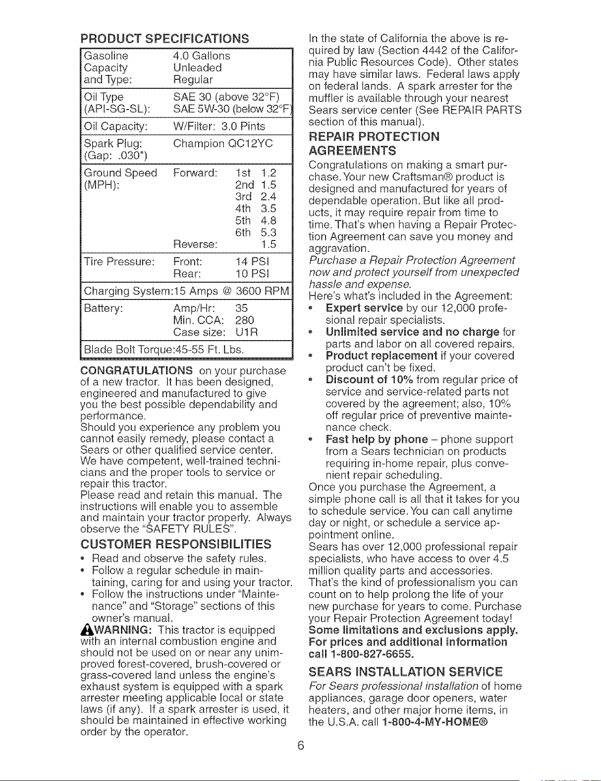
PRODUCT SPECmFmCATmONS
Gasoline 4.0 Gallons
Capacity Unleaded
and Type: Regular
Oil Type SAE 30 (above 32°F)
(API-SG-SL): SAE 5W-30 (below 32°F
Oil Capacity: W/Filter: 3.0 Pints
Spark Plug: Champion QC12YC
(Gap: .030")
Ground Speed Forward: 1st 1.2
(MPH): 2nd 1.5
3rd 2.4
4th 3.5
5th 4.8
6th 5.3
Reverse: 1.5
Tire Pressure: Front: 14 PSI
Rear: 10 PSI
Charging System:15 Amps @ 3600 RPM
Battery: Amp/Hr: 35
Min. CCA: 280
Case size: U1R
Blade Bolt Torque:45-55 Ft. Lbs.
CONGRATULATmONS on your purchase
of a new tractor. It has been designed,
engineered and manufactured to give
you the best possible dependability and
performance.
Should you experience any problem you
cannot easily remedy, please contact a
Sears or other qualified service center.
We have competent, well-trained techni-
cians and the proper tools to service or
repair this tractor.
Please read and retain this manual. The
instructions will enable you to assemble
and maintain your tractor properly. Always
observe the "SAFETY RULES".
CUSTOMER RESPONSmBILmES
* Read and observe the safety rules.
,, Follow a regular schedule in main-
taining, caring for and using your tractor.
,, Follow the instructions under "Mainte-
nance" and "Storage" sections of this
owner's manual.
_,WARNING: This tractor is equipped
with an internal combustion engine and
should not be used on or near any unim-
proved forest-covered, brush-covered or
grass-covered land unless the engine's
exhaust system is equipped with a spark
arrester meeting applicable local or state
laws (if any). If a spark arrester is used, it
should be maintained in effective working
order by the operator.
In the state of California the above is re-
quired by law (Section 4442 of the Califor-
nia Public Resources Code). Other states
may have similar laws. Federal laws apply
on federal lands. A spark arrester for the
muffler is availaNe through your nearest
Sears service center (See REPAIR PARTS
section of this manual).
REPAIR PROTECTmON
AGREEMENTS
Congratulations on making a smart pur-
chase. Your new Craftsman@ product is
designed and manufactured for years of
dependable operation. But like all prod-
ucts, it may require repair from time to
time. That's when having a Repair Protec-
tion Agreement can save you money and
aggravation.
Purchase a Repair Protection Agreement
now and protect yourseff from unexpected
hassle and expense.
Here's what's included in the Agreement:
,, Expert service by our 12,000 profe-
sional repair specialists.
,, Unlimited service and no charge for
parts and labor on all covered repairs.
,, Product replacement if your covered
product can't be fixed.
,, Discount of 10% from regular price of
service and service-related parts not
covered by the agreement; also, 10%
off regular price of preventive mainte-
nance check.
,, Fast help by phone- phone support
from a Sears technician on products
requiring in-home repair, plus conve-
nient repair scheduling.
Once you purchase the Agreement, a
simple phone call is all that it takes for you
to schedule service. You can call anytime
day or night, or schedule a service ap-
pointment online.
Sears has over 12,000 professional repair
specialists, who have access to over 4.5
million quality parts and accessories.
That's the kind of professionalism you can
count on to help prolong the life of your
new purchase for years to come. Purchase
your Repair Protection Agreement today!
Some limitations and exclusions apply.
For prices and additional information
call 1-800-827-8655.
SEARS mNSTALLATmON SERWCE
For Sears professional installation of home
appliances, garage door openers, water
heaters, and other major home items, in
the U.S.A. call 1-800-4-MY-HOME®
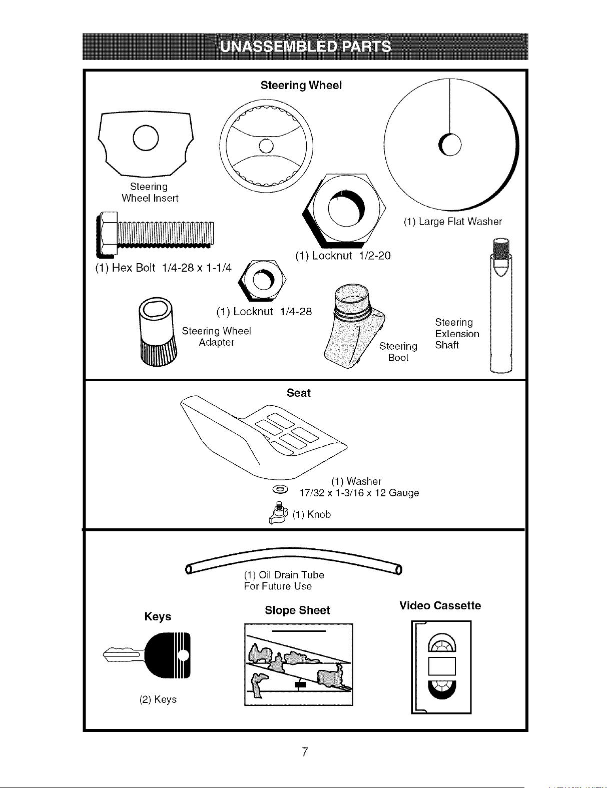
Steering Wheel
Steering
Wheel Insert
(1) Locknut 1/2-20
(1) Hex Bolt 1/4-28 x 1-1/4
(1) Locknut 1/4-28
Steering Wheel
Adapter Steering
Boot
Seat
(1) Large Flat Washer
m
Steering
Extension
Shaft
(1) Washer
@ 17/32 x1-3/16 x12 Gauge
_(1 ) Knob
Keys
(1) Oil Drain Tube
For Future Use
Slope Sheet
Video Cassette
(2) Keys
Your new tractor has been assembled at the factory with the exception of those parts left
unassembled for shipping purposes. To ensure safe and proper operation of your tractor
all parts and hardware you assemble must be tightened securely. Use the correct tools
as necessary to insure proper tightness. Review the video cassette before you begin.
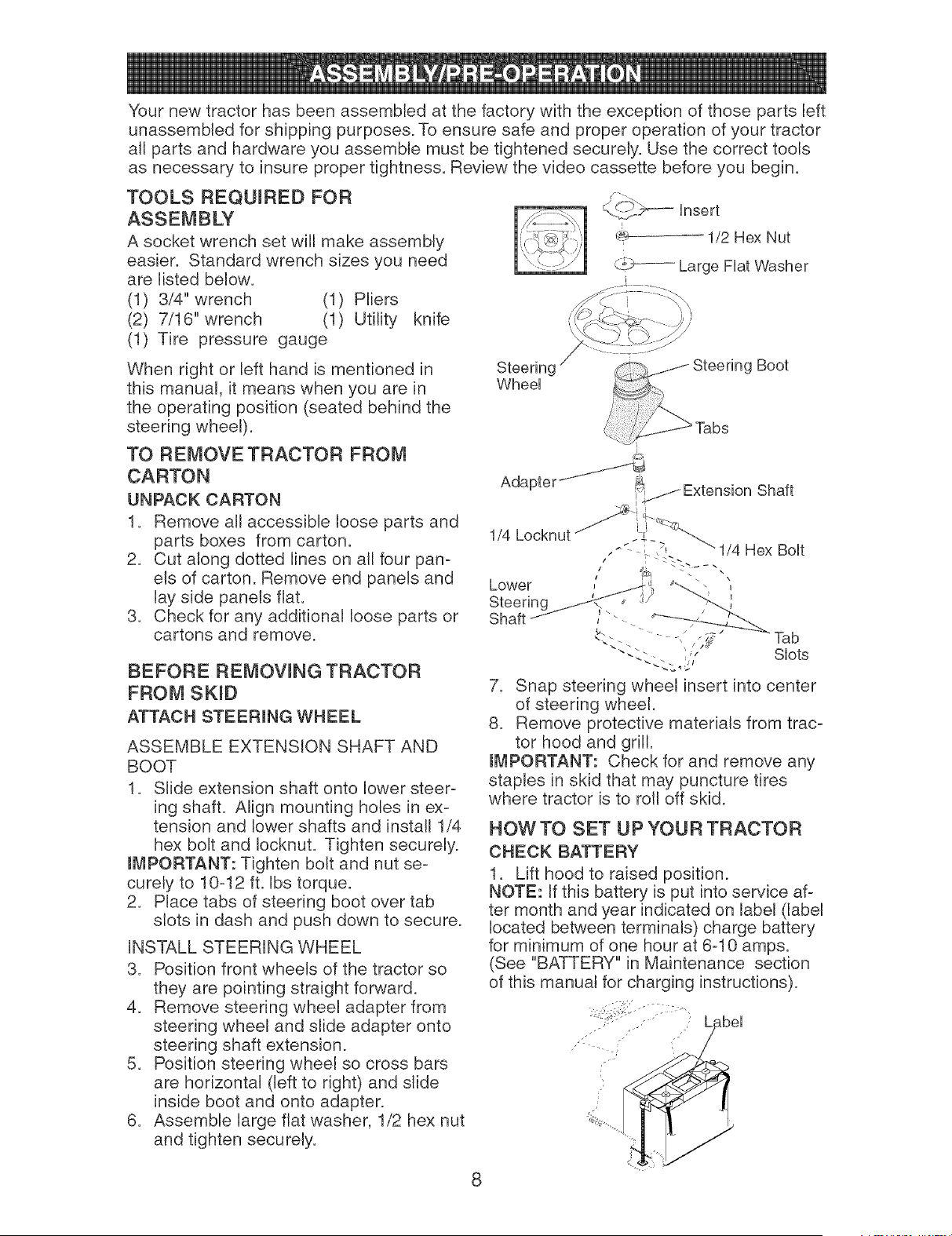
TOOLS REQUmRED FOR
A socket wrench set will make assembly
easier. Standard wrench sizes you need
are listed below.
(1) 3/4" wrench (1) Pliers
(2) 7/16" wrench (1) Utility knife
(1) Tire pressure gauge
_-_c:-_'b_--Unsert
L
_ 1/2 Hex Nut
(1£-._------Large FUatWasher
When right or left hand is mentioned in
this manual, it means when you are in
the operating position (seated behind the
steering wheel).
TO REMOVE TRACTOR FROM
CARTON
UNPACK CARTON
1. Remove all accessible loose parts and
parts boxes from carton.
2. Cut along dotted lines on all four pan-
els of carton. Remove end panels and
lay side panels flat.
3. Check for any additional loose parts or
cartons and remove.
BEFORE REMOVmNG TRACTOR
FROM SKID
ATTACH STEERmNG WHEEL
ASSEMBLE EXTENSION SHAFT AND
BOOT
1. Slide extension shaft onto lower steer-
ing shaft. Align mounting holes in ex-
tension and lower shafts and install 1/4
hex bolt and Iocknut. Tighten securely.
mMPORTANT: Tighten bolt and nut se-
curely to 10-12 ft. Ibs torque.
2. Place tabs of steering boot over tab
slots in dash and push down to secure.
iNSTALL STEERING WHEEL
3. Position front wheels of the tractor so
they are pointing straight forward.
4. Remove steering wheel adapter from
steering wheel and slide adapter onto
steering shaft extension.
5. Position steering wheel so cross bars
are horizontal (left to right) and slide
inside boot and onto adapter.
6. Assemble large flat washer, 1/2 hex nut
and tighten securely.
Steering
WheeU
AdapterJJ
Steering Boot
_Tabs
Extension Shaft
1/4
Hex BoUt
Tab
"-,- -. ;,/ SUots
7. Snap steering wheel insert into center
of steering wheel.
8. Remove protective materials from trac-
tor hood and grill.
mMPORTANT: Check for and remove any
staples in skid that may puncture tires
where tractor is to roll off skid.
HOW TO SET UP YOUR TRACTOR
CHECK BATTERY
1. Lift hood to raised position.
NOTE: If this battery is put into service af-
ter month and year indicated on label (label
located between terminals) charge battery
for minimum of one hour at 6-10 amps.
(See "BATTERY" in Maintenance section
of this manual for charging instructions).
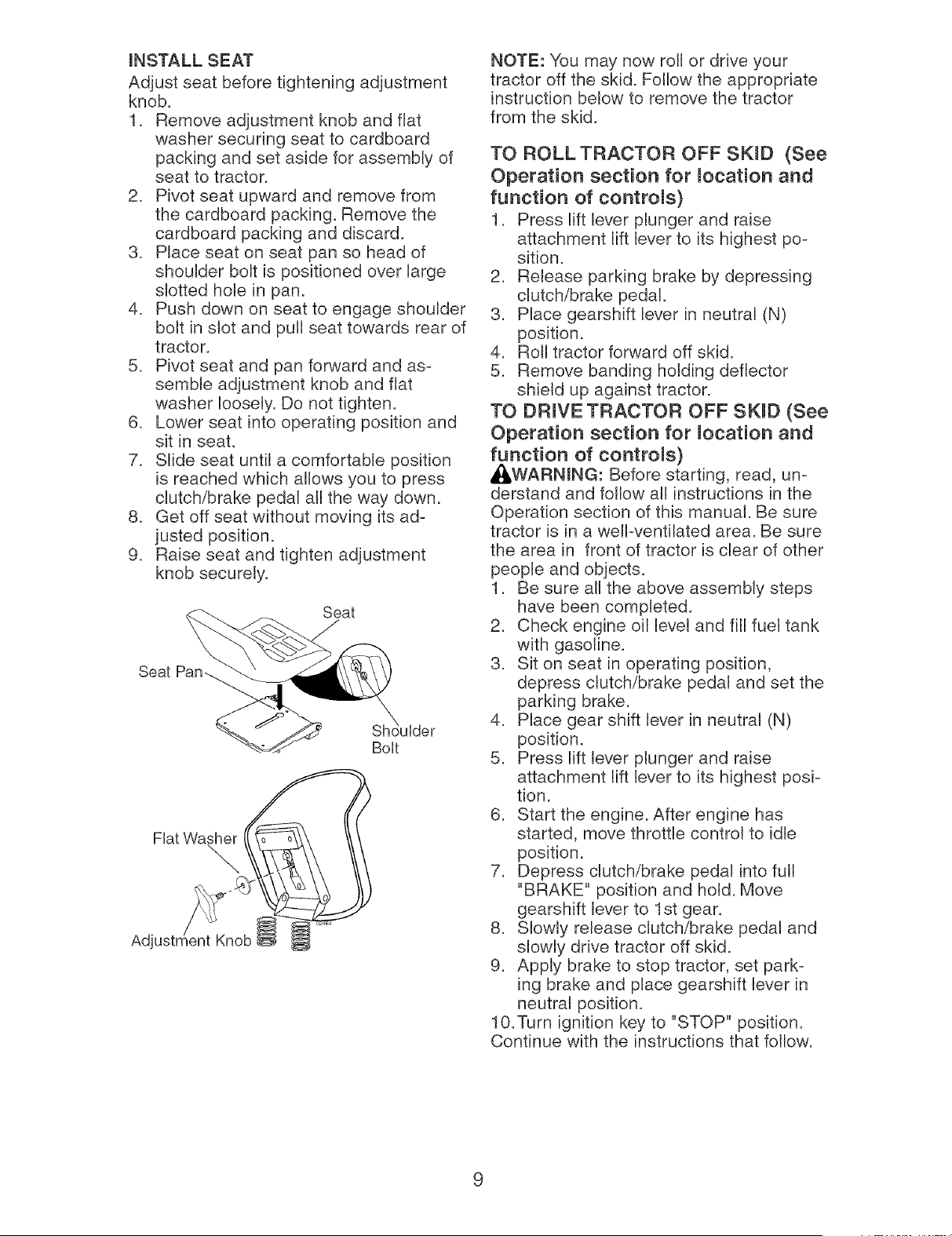
mNSTALLSEAT
Adjust seat beforetighteningadjustment
knob.
1. Removeadjustmentknob and flat
washersecuring seatto cardboard
packingand set asidefor assemblyof
seatto tractor.
2. Pivotseat upwardand removefrom
the cardboardpacking.Removethe
cardboardpackingand discard.
3. Placeseat on seat pan so head of
shoulderbolt is positionedover large
slotted holein pan.
4. Push downon seat to engageshoulder
bolt in slot and pullseat towardsrear of
tractor.
5. Pivotseat and pan forwardand as-
sembleadjustmentknoband flat
washerloosely.Do not tighten.
6. Lowerseat into operatingpositionand
sit in seat.
7. Slideseat until a comfortableposition
is reachedwhich allowsyou to press
clutch/brakepedal all the way down.
8. Get off seatwithout movingits ad-
justed position.
9. Raiseseat and tightenadjustment
knob securely.
Seat
Seat
BoUt
Fiat Washer
Adjm Knob
NOTE: You may now roll or drive your
tractor off the skid. Follow the appropriate
instruction below to remove the tractor
from the skid.
TO ROLL TRACTOR OFF SKiD (See
Operation section for mocation and
function of controms)
1. Press lift lever plunger and raise
attachment lift lever to its highest po-
sition.
2. Release parking brake by depressing
clutch/brake pedal.
3. Place gearshift lever in neutral (N)
position.
4. Roll tractor forward off skid.
5. Remove banding holding deflector
shield up against tractor.
TO DRmVE TRACTOR OFF SKID (See
Operation section for mocation and
function of controms)
_WARNmNG: Before starting, read, un-
derstand and follow all instructions in the
Operation section of this manual. Be sure
tractor is in a well-ventilated area. Be sure
the area in front of tractor is clear of other
people and objects.
1. Be sure all the above assembly steps
have been completed.
2. Check engine oil level and fill fuel tank
with gasoline.
3. Sit on seat in operating position,
depress clutch/brake pedal and set the
parking brake.
4. Place gear shift lever in neutral (N)
position.
5. Press lift lever plunger and raise
attachment lift lever to its highest posi-
tion.
6. Start the engine. After engine has
started, move throttle control to idle
position.
7. Depress clutch/brake pedal into full
"BRAKE" position and hold. Move
gearshift lever to 1st gear.
8. Slowly release clutch/brake pedal and
slowly drive tractor off skid.
9. Apply brake to stop tractor, set park-
ing brake and place gearshift lever in
neutral position.
10.Turn ignition key to "STOP" position.
Continue with the instructions that follow.
9
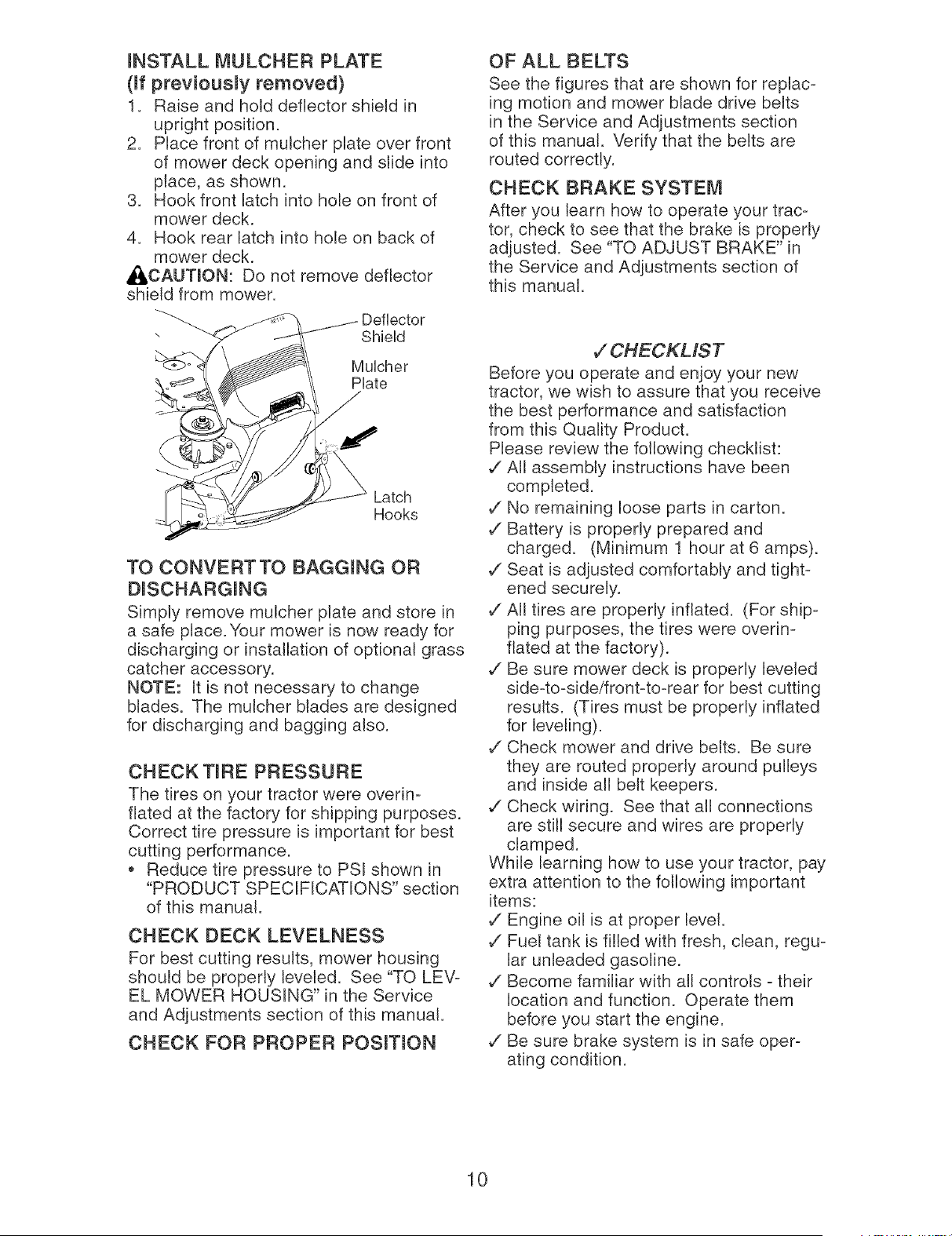
mNSTALL MULCHER PLATE
(ff previousmy removed)
1. Raise and hold deflector shield in
upright position.
2. Place front of mulcher plate over front
of mower deck opening and slide into
place, as shown.
3. Hook front latch into hole on front of
mower deck.
4. Hook rear latch into hole on back of
mower deck.
_,CAUTmON: Do not remove deflector
shield from mower.
Deflector
Shield
Mulcher
Plate
Latch
Hooks
TO CONVERTTO BAGGING OR
DISCHARGING
Simply remove mulcher plate and store in
a safe place. Your mower is now ready for
discharging or installation of optional grass
catcher accessory.
NOTE: It is not necessary to change
blades. The mulcher blades are designed
for discharging and bagging also.
CHECK TIRE PRESSURE
The tires on your tractor were ovedn-
fiated at the factory for shipping purposes.
Correct tire pressure is important for best
cutting performance.
,, Reduce tire pressure to PSI shown in
"PRODUCT SPECIFICATIONS" section
of this manual.
CHECK DECK LEVELNESS
For best cutting results, mower housing
should be properly leveled. See "TO LEV-
EL MOWER HOUSING" in the Service
and Adjustments section of this manual.
CHECK FOR PROPER POSmON
OF ALL BELTS
See the figures that are shown for replac-
ing motion and mower blade drive belts
in the Service and Adjustments section
of this manual. Verify that the belts are
routed correctly.
CHECK BRAKE SYSTEM
After you learn how to operate your trac-
tor, check to see that the brake is properly
adjusted. See "TO ADJUST BRAKE" in
the Service and Adjustments section of
this manual.
V"CHECKMST
Before you operate and enjoy your new
tractor, we wish to assure that you receive
the best performance and satisfaction
from this Quality Product.
Please review the following checklist:
v" All assembly instructions have been
completed.
v" No remaining loose parts in carton.
v" Battery is properly prepared and
charged. (Minimum 1 hour at 6 amps).
v" Seat is adjusted comfortably and tight-
ened securely.
v" All tires are properly inflated. (For ship-
ping purposes, the tires were overin-
fiated at the factory).
v" Be sure mower deck is properly leveled
side-to-sideifront-to-rear for best cutting
results. (Tires must be properly inflated
for leveling).
v" Check mower and drive belts. Be sure
they are routed properly around pulleys
and inside all belt keepers.
v" Check wiring. See that all connections
are still secure and wires are properly
clamped.
While learning how to use your tractor, pay
extra attention to the following important
items:
,/Engine oil is at proper level.
v" Fuel tank is filled with fresh, clean, regu-
lar unleaded gasoline.
v" Become familiar with all controls - their
location and function. Operate them
before you start the engine.
v" Be sure brake system is in safe oper-
ating condition.
10
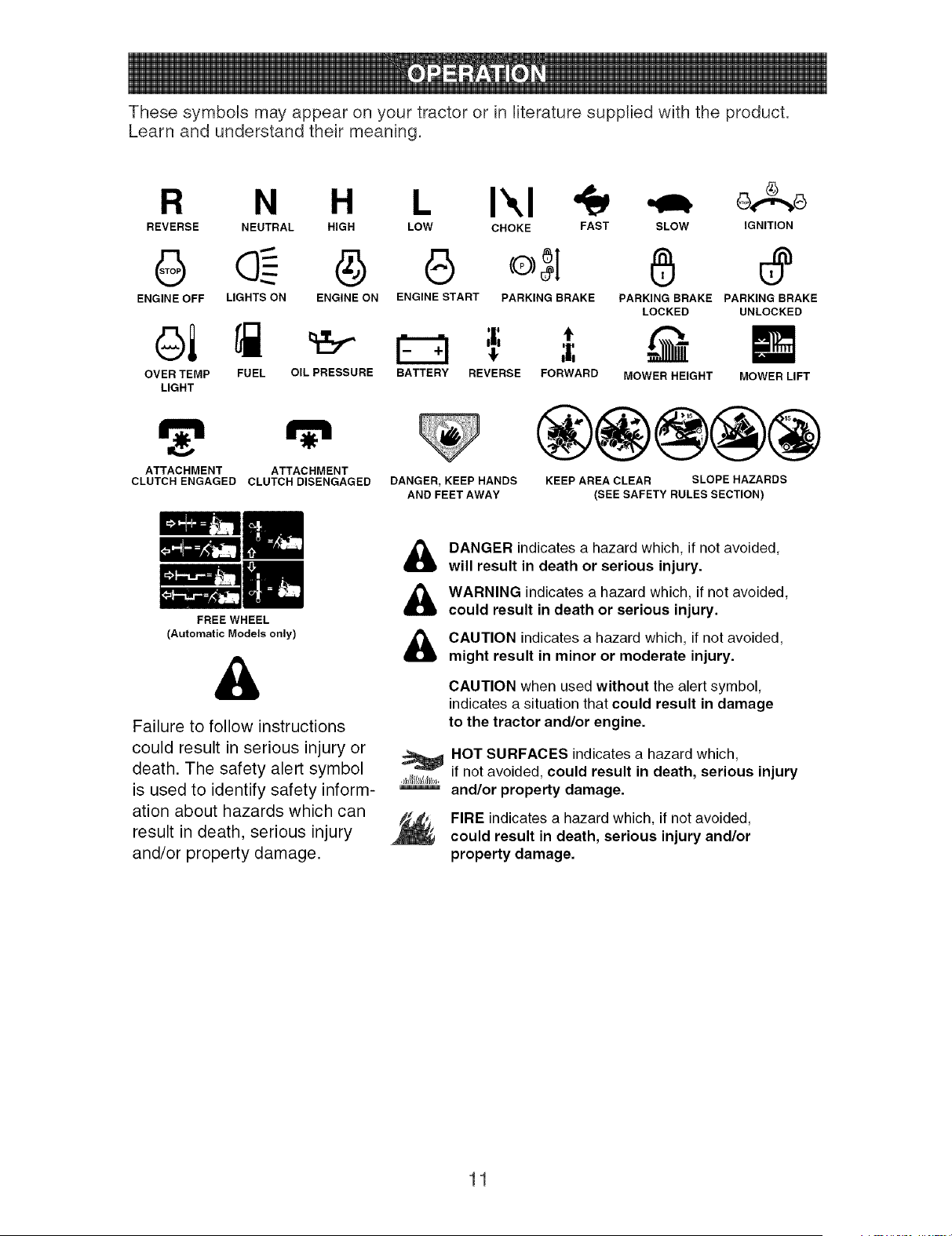
These symbols may appear on your tractor or in literature supplied with the product.
Learn and understand their meaning.
R N H L Ikl _ _,_
REVERSE NEUTRAL HIGH LOW CHOKE FAST SLOW IGNITION
G G
ENGINE OFF LIGHTS ON ENGINE ON ENGINE START PARKING BRAKE
ol
OVER TEMP FUEL OIL PRESSURE
LIGHT
t
BATTERY REVERSE FORWARD
ATTACHMENT ATTACHMENT
CLUTCH ENGAGED CLUTCH DISENGAGED
FREE WHEEL
(Automatic Models only)
DANGER, KEEP HANDS
AND FEET AWAY
6
PARKING BRAKE PARKING BRAKE
LOCKED UNLOCKED
MOWER HEIGHT MOWER LIFT
®@@@@
KEEP AREA CLEAR SLOPE HAZARDS
(SEE SAFETY RULES SECTION)
&
Failure to follow instructions
could result in serious injury or
death. The safety alert symbol
is used to identify safety inform-
ation about hazards which can
result in death, serious injury
and/or property damage.
&
&
&
,_hlI/lllIJll/,,
DANGER indicates a hazard which, if not avoided,
will result in death or serious injury.
WARNING indicates a hazard which, if not avoided,
could result in death or serious injury.
CAUTION indicatesa hazard which, if not avoided,
might result in minor or moderate injury.
CAUTION when used without the alert symbol,
indicates a situation that could result in damage
to the tractor and/or engine.
HOT SURFACES indicates a hazard which,
if not avoided, could result in death, serious injury
and/or property damage.
FIRE indicatesa hazard which, if not avoided,
could result in death, serious injury and/or
property damage.
11
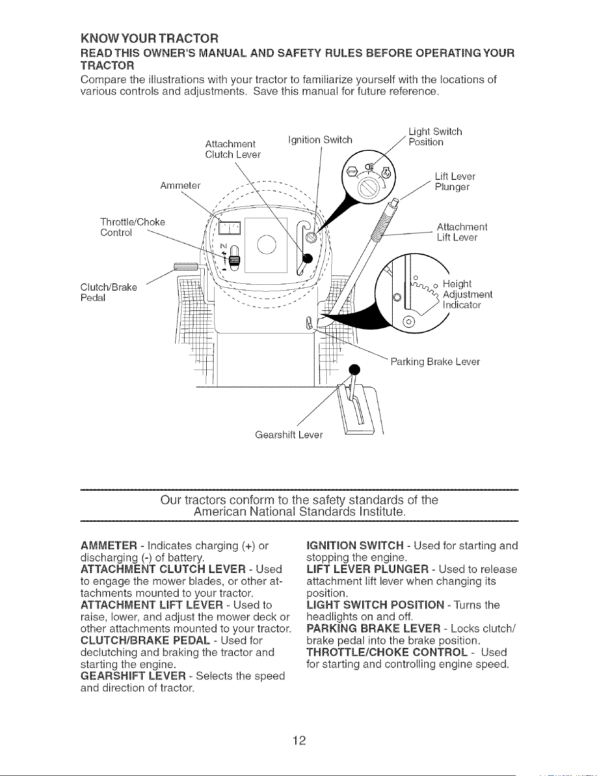
KNOW YOUR TRACTOR
READTHINSOWNER'SMANUAL AND SAFETYRULES BEFOREOPERATmNGYOUR
TRACTOR
Comparethe illustrationswith your tractorto familiarizeyourselfwith the locationsof
variouscontrols and adjustments. Savethis manualfor futurereference.
Attachment
CDtch Lever
Ammeter
-\
Throttb/Choke
Control
Light Switch
ignition Switch Position
Lift Lever
_ Plunger
Attachment
Lift Lever
Clutch/Brake
Pedal
o Height
indicator
Parking Brake Lever
Gearshift Lever
Our tractors conform to the safety standards of the
American National Standards anstitute.
AMMETER - Indicates charging (+) or
discharging (-) of battery.
ATTACHMENT CLUTCH LEVER - Used
to engage the mower blades, or other at-
tachments mounted to your tractor.
ATTACHMENT LiFT LEVER - Used to
raise, lower, and adjust the mower deck or
other attachments mounted to your tractor.
CLUTCH/BRAKE PEDAL - Used for
declutching and braking the tractor and
starting the engine.
GEARSHmFT LEVER - Selects the speed
and direction of tractor.
mGNmON SWITCH - Used for starting and
stopping the engine.
UFT LEVER PLUNGER - Used to release
attachment lift lever when changing its
position.
UGHT SWmTCH POSmON - Turns the
headlights on and off.
PARKmNG BRAKE LEVER - Locks clutch/
brake pedal into the brake position.
THROTTLE/CHOKE CONTROL - Used
for starting and controlling engine speed.
12
The operation of any tractor can result in foreign objects thrown into
the eyes, which can result in severe eye damage. Always wear safety
glasses or eye shields while operating your tractor or performing any
adjustments or repairs. We recommend a wide vision safety mask over
spectacles or standard safety glasses.
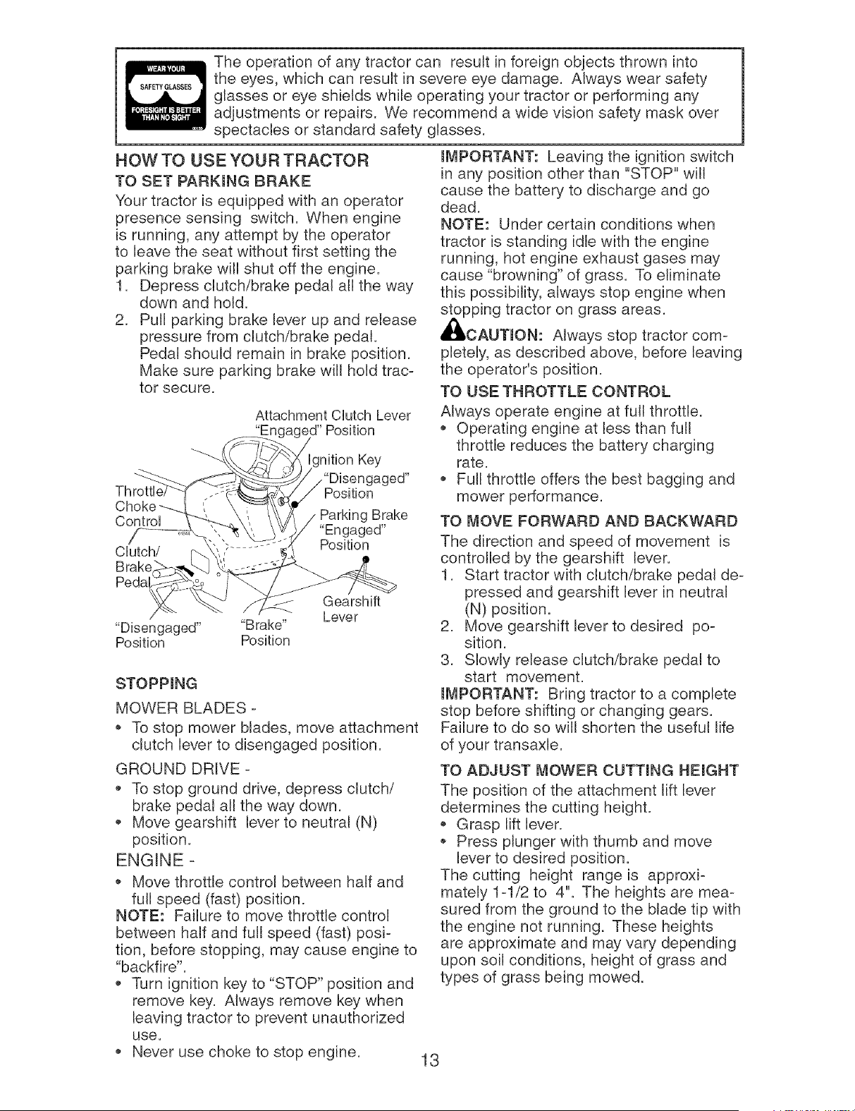
HOW TO USE YOUR TRACTOR
TO SET PARKING BRAKE
Your tractor is equipped with an operator
presence sensing switch. When engine
is running, any attempt by the operator
to leave the seat without first setting the
parking brake will shut off the engine.
1. Depress clutch/brake pedal all the way
down and hold.
2. Pull parking brake lever up and release
pressure from clutch/brake pedal.
Pedal should remain in brake position.
Make sure parking brake will hold trac-
tor secure.
Attachment CUutch Lever
"Eric ed" Position
Choke
ControU Parking Brake
"Engaged"
Clutch/ Position
Brake
Pedal
STOPPING
MOWER BLADES -
* To stop mower blades, move attachment
clutch lever to disengaged position.
IMPORTANT: Leaving the ignition switch
in any position other than "STOP" will
cause the battery to discharge and go
dead.
NOTE: Under certain conditions when
tractor is standing idle with the engine
running, hot engine exhaust gases may
cause "browning" of grass. To eliminate
this possibility, always stop engine when
stopping tractor on grass areas.
_CAUTION: Always stop tractor com-
pletely, as described above, before leaving
the operator"s position.
TO USE THROTTLE CONTROL
Always operate engine at full throttle.
Operating engine at less than full
throttle reduces the battery charging
rate.
Full throttle offers the best bagging and
mower performance.
TO MOVE FORWARD AND BACKWARD
The direction and speed of movement is
controlled by the gearshift lever.
1. Start tractor with clutch/brake pedal de-
pressed and gearshift lever in neutral
(N) position.
2. Move gearshift lever to desired po-
sition.
3. Slowly release clutch/brake pedal to
start movement.
IMPORTANT: Bring tractor to a complete
stop before shifting or changing gears.
Failure to do so will shorten the useful life
of your transaxle.
GROUND DRIVE -
To stop ground drive, depress clutch/
brake pedal all the way down.
Move gearshift lever to neutral (N)
position.
ENGINE -
Move throttle control between half and
full speed (fast) position.
NOTE: Failure to move throttle control
between half and full speed (fast) posi-
tion, before stopping, may cause engine to
"backfire".
Turn ignition key to "STOP" position and
remove key. Always remove key when
leaving tractor to prevent unauthorized
use.
,, Never use choke to stop engine.
TO ADJUST MOWER CUTTING HEIGHT
The position of the attachment lift lever
determines the cutting height.
Grasp lift lever.
Press plunger with thumb and move
lever to desired position.
The cutting height range is approxi-
mately 1-1/2 to 4". The heights are mea-
sured from the ground to the blade tip with
the engine not running. These heights
are approximate and may vary depending
upon soil conditions, height of grass and
types of grass being mowed.
13
• The average lawn should be cut to approxi-
mately 2-1/2 inches during the cool season
and to over 3 inches during hot months.
For healthier and better looking lawns, mow
often and after moderate growth.
For best cutting performance, grass
over 6 inches in height should be
mowed twice. Make the first cut rela-
tively high; the second to desired height.
TO ADJUST GAUGE WHEELS
Gauge wheels are properly adjusted
when they are slightly off the ground when
mower is at the desired cutting height in
operating position. Gauge wheels then
keep the deck in proper position to help
prevent scalping in most terrain conditions.
NOTE: Be sure tractor is on a flat level
surface.
1. Lower mower and adjust mower to de-
sired cutting height(See "TO ADJUST
MOWER CUTTING HEIGHT" in this
section of manual).
2. Remove retainer spring and clevis pin
which secure each gauge wheel bar.
3. Lower gauge wheels to ground. Raise
gauge wheels slightly to align holes
in bracket and gauge wheel bar and
insert clevis pin. Gauge wheels should
be slightly off the ground.
4. Replace retainer spring into clevis pin.
5. Be sure all gauge wheels are in the
same setting.
mMPORTANT: Be sure to readjust gauge
wheels if you change the cutting height
of the mower deck.
J
Retainer
Spring
Clevis
Pin
TO OPERATE MOWER
Your tractor is equipped with an operator
presence sensing switch. Any attempt
by the operator to leave the seat with the
engine running and the attachment clutch
engaged will shut off the engine. You must
remain fully and centrally positioned in the
seat to prevent the engine from hesitating
or cutting off when operating your equip-
ment on rough, roiling terrain or hills.
1. Select desired height of cut.
2. Start mower blades by engaging at-
tachment clutch control.
TO STOP MOWER BLADES -
disengage attachment clutch control.
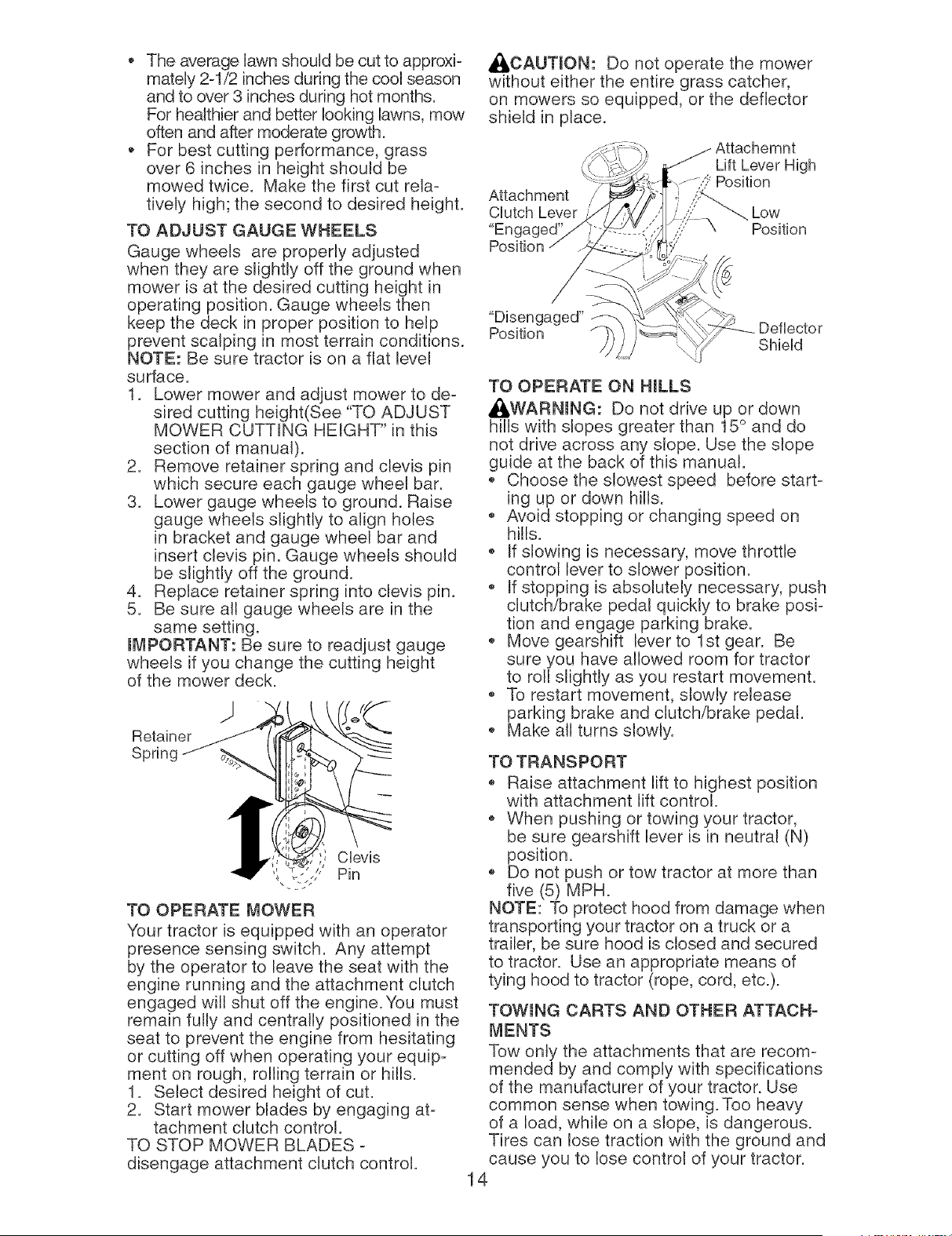
_CAUTION: Do not operate the mower
without either the entire grass catcher,
on mowers so equipped, or the deflector
shield in place.
Lift Lever High
Position
Attachment
Clutch Lever Low
"Engaged' Position
//
"Disengaged"
Position
Shield
TO OPERATE ON HmLLS
_b,WARNmNG: Do not drive up or down
hills with slopes greater than 15 ° and do
not drive across any slope. Use the slope
guide at the back of this manual.
• Choose the slowest speed before start-
ing up or down hills.
• Avoid stopping or changing speed on
hills.
If slowing is necessary, move throttle
control lever to slower position.
• If stopping is absolutely necessary, push
clutch/brake pedal quickly to brake posi-
tion and engage parking brake.
• Move gearshift lever to 1st gear. Be
sure you have allowed room for tractor
to roll slightly as you restart movement.
• To restart movement, slowly release
parking brake and clutch/brake pedal.
• Make all turns slowly.
TO TRANSPORT
• Raise attachment lift to highest position
with attachment lift control.
, When pushing or towing your tractor,
be sure gearshift lever is in neutral (N)
position.
• Do not push or tow tractor at more than
five (5) MPH.
NOTE: To protect hood from damage when
transporting your tractor on a truck or a
trailer, be sure hood is closed and secured
to tractor. Use an appropriate means of
tying hood to tractor (rope, cord, etc.).
TOWmNG CARTS AND OTHER ATTACH-
MENTS
Tow only the attachments that are recom-
mended by and comply with specifications
of the manufacturer of your tractor. Use
common sense when towing. Too heavy
of a load, while on a slope, is dangerous.
Tires can lose traction with the ground and
cause you to lose control of your tractor.
14
BEFORE STARTmNGTHE ENGmNE
CHECK ENGmNEOraLLEVEL
The engine in your tractor has been
shipped, from the factory, already filled
with summer weight oil.
1. Check engine oil with tractor on level
ground.
2. Pull up and remove oil fill cap/dipstick;
wipe oil off. Reinsert the dipstick into
the tube and push down firmly into
place. Remove and read oil level. If
necessary, add oil until "FULL:' mark
on dipstick is reached. Do not overfill.
• For cold weather operation you should
change oil for easier starting (See the
oil viscosity chart in the Maintenance
section of this manual).
• To change engine oil, see the Mainte-
nance section in this manual.
ADD GASOUNE
• Fill fuel tank to bottom of filler neck. Do
not overfill. Use fresh, clean, regular
unleaded gasoline with a minimum of
87 octane. (Use of leaded gasoline will
increase carbon and lead oxide deposits
and reduce valve life). Do not mix oil
with gasoline. Purchase fuel in quan-
tities that can be used within 30 days to
assure fuel freshness.
_I_CAUTmON: Wipe off any spilled oil or
fuel. Do not store, spill or use gasoline
near an open flame.
mMPORTANT: When operating in temper-
atures below32°F(0°C), use fresh, clean
winter grade gasoline to help insure good
cold weather starting.
CAUTmON: Alcohol blended fuels (called
gasohol or using ethanol or methanol) can
attract moisture which leads to separa-
tion and formation of acids during storage.
Acidic gas can damage the fuel system
of an engine while in storage. To avoid
engine problems, the fuel system should
be emptied before storage of 30 days
or longer. Drain the gas tank, start the
engine and Jet it run until the fuel lines
and carburetor are empty. Use fresh fuel
next season. See Storage Instructions for
additional information. Never use engine
or carburetor cleaner products in the fuel
tank or permanent damage may occur.
TO START ENGINE
When starting the engine for the first time
or if the engine has run out of fuel, it will
take extra cranking time to move fuel from
the tank to the engine.
1. Sit on seat in operating position,
depress clutch/brake pedat and set
parking brake.
2. Place gear shift lever in neutral (N)
position.
3. Move attachment clutch to disengaged
position.
4. Move throttle control to choke position.
NOTE: Before starting, read the warm
and cold starting procedures below.
5. Insert key into ignition and turn key
clockwise to start position and release
key as soon as engine starts. Do
not run starter continuously for more
than fifteen seconds per minute. If the
engine does not start after several
attempts, move throttle control to fast
position, wait a few minutes and try
again. If engine still does not start,
move the throttle control back to the
choke position and retry.
WARM WEATHER STARTING (50 ° F and
above)
6. When engine starts, move the throttle
control to the fast position.
• The attachments and ground drive can
now be used. If the engine does not
accept the load, restart the engine and
allow it to warm up for one minute using
the choke as described above.
COLD WEATHER STARTING ( 50 ° F and
below)
6. When engine starts, leave throttle
control in choke position until engine
warms up and begins to run roughly.
Once rough running begins, imme-
diately move the throttle control to the
fast position. Engine warm-up may
take from several seconds to several
minutes (the colder the temperature,
the longer the warm-up).
The attachments can also be used dur-
ing the engine warm-up period.
NOTE: If at a high altitude (above 3000
feet) or in cold temperatures (below 32 F)
the carburetor fuel mixture may need to
be adjusted for best engine performance
(see "TO ADJUST CARBURETOR" in the
Service and Adjustments section of this
manual).
15
MOWING TIPS
Mower should be properly leveled for
best mowing performance. See "TO
LEVEL MOWER HOUSING" in the
Service and Adjustments section of this
manual.
The left hand side of mower should be
used for trimming.
Drive so that clippings are discharged
onto the area that has already been
cut. Have the cut area to the right of
the tractor. This will result in a more
even distribution of clippings and more
uniform cutting.
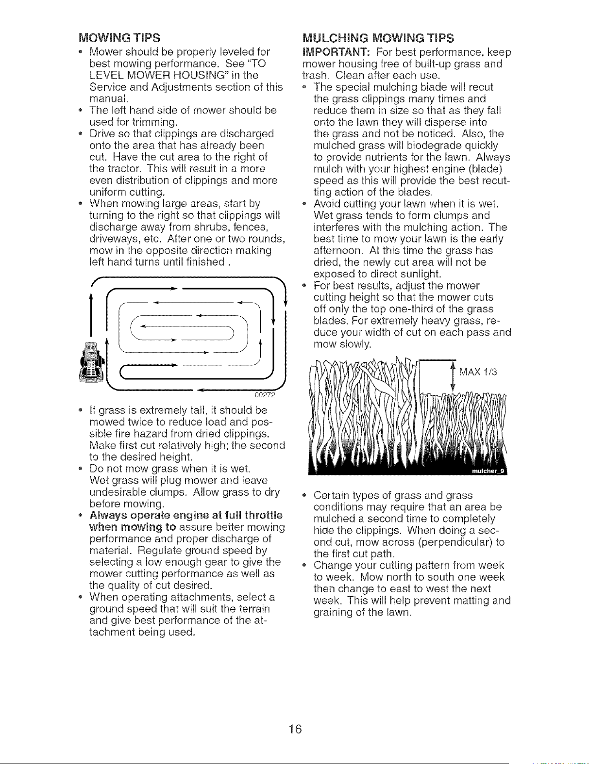
When mowing large areas, start by
turning to the right so that clippings will
discharge away from shrubs, fences,
driveways, etc. After one or two rounds,
mow in the opposite direction making
left hand turns until finished.
MULCHING MOWING TIPS
IMPORTANT: For best performance, keep
mower housing free of built-up grass and
trash. Clean after each use.
,, The speciat mulching blade will recut
the grass clippings many times and
reduce them in size so that as they fall
onto the lawn they will disperse into
the grass and not be noticed. Also, the
mulched grass will biodegrade quickly
to provide nutrients for the lawn. Always
mulch with your highest engine (blade)
speed as this will provide the best recut-
ting action of the blades.
,, Avoid cutting your lawn when it is wet.
Wet grass tends to form clumps and
interferes with the mulching action. The
best time to mow your lawn is the early
afternoon. At this time the grass has
dried, the newly cut area will not be
exposed to direct sunlight.
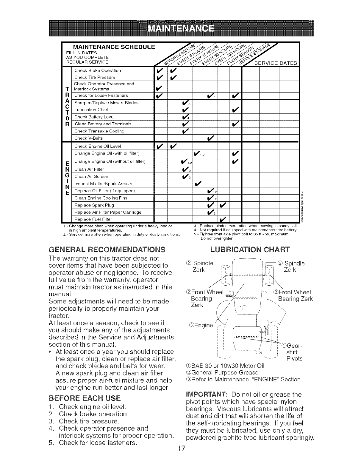
For best results, adjust the mower
cutting height so that the mower cuts
off only the top one-third of the grass
blades. For extremely heavy grass, re-
duce your width of cut on each pass and
mow slowly.
f
(
-- 4[
(.
J
, J
00272
If grass is extremely tall, it should be
mowed twice to reduce load and pos-
sible fire hazard from dried clippings.
Make first cut relatively high; the second
to the desired height.
Do not mow grass when it is wet.
Wet grass will plug mower and leave
undesirable clumps. Allow grass to dry
before mowing.
Always operate engine at full throttle
when mowing to assure better mowing
performance and proper discharge of
material. Regulate ground speed by
selecting a low enough gear to give the
mower cutting performance as well as
the quality of cut desired.
When operating attachments, select a
ground speed that will suit the terrain
and give best performance of the at-
tachment being used.
MAX 1/3
Certain types of grass and grass
conditions may require that an area be
mulched a second time to completely
hide the clippings. When doing a sec-
ond cut, mow across (perpendicular) to
the first cut path.
Change your cutting pattern from week
to week. Mow north to south one week
then change to east to west the next
week. This will help prevent matting and
graining of the lawn.
16
FILL IN DATES
AS YOU CO MPLETE J_/_G_7
v _.',:: £.'£ e..'£ e..'£ ",o t"-'
REOULARSERV,OE ,,' ZSERV,OE OATES
Check Brake Operation _1_ I_
Check Tire Pressure
Check Operator Presence and
T Interlock Systems
R Check for Loose Fasteners I_ Ks
A Sharpen/Replace Mower Blades 1_3
C Lubrication Chart li_ If
0 Check Battery Level _4
R Clean Battery and Terminals If I_
Check Transaxle Cooling
Check V-Belts If
Check Engine Oil Level I_ If
Change Engine Oil (with oil filter) _1,2
E Change Engine Oil (without oil filter) 1_1,2
N Clean Air Filter _1_2
G Clean Air Screen 1_2
Inspect Muffler/Spark
Arrester
v'
E Replace Oil Filter (If equipped) 1_,2
Clean Engine Cooling Fins I_ 2
Replace Spark Plug I_ If
Replace Air Filter Paper Cartridge 1_2
Replace Fuel Filter
1 - Change more often when operating under a heavy load or
in high ambient temperatures.
2 - Service more often when operating in dirty or dusly conditions.
3 - Replace blades more often when mowing in sandy soil.
4 - Not required if equipped with maintenance-free battery.
5 - Tighten front axle pivot bolt to 35 fb-lbs, maximum.
Do not overtighten.
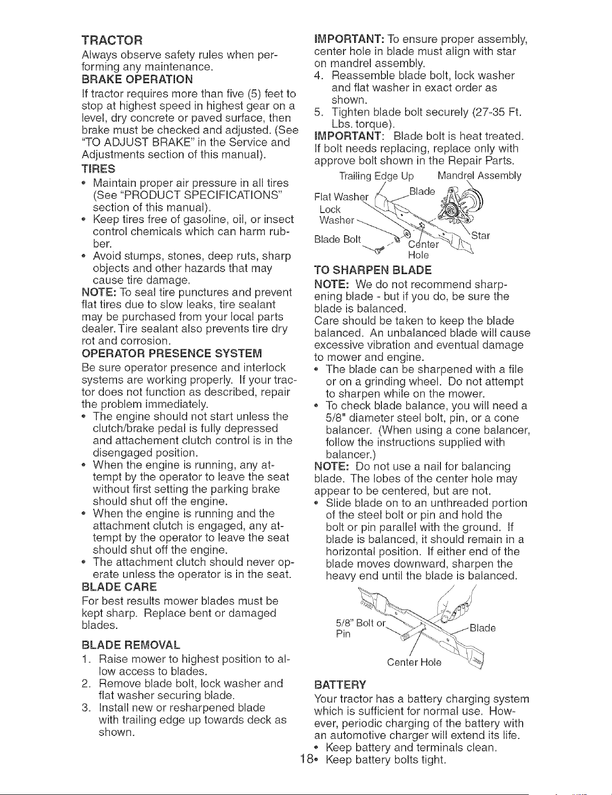
GENERAL RECOMMENDATmONS
The warranty on this tractor does not
cover items that have been subjected to
operator abuse or negligence. To receive
full value from the warranty, operator
must maintain tractor as instructed in this
manual.
Some adjustments will need to be made
periodically to properly maintain your
tractor.
At least once a season, check to see if
you should make any of the adjustments
described in the Service and Adjustments
section of this manual.
At least once a year you should replace
the spark plug, clean or replace air filter,
and check blades and belts for wear.
A new spark plug and clean air filter
assure proper air-fuel mixture and help
your engine run better and last longer.
BEFORE EACH USE
1. Check engine oil level.
2. Check brake operation.
3. Check tire pressure.
4. Check operator presence and
interlock systems for proper operation.
5. Check for loose fasteners.
LUBRICATION CHART
@ Spindb -@ Spindb
Zerk Zerk
@Front WheeU ,
Bearing
Zerk
@Front Wheel
Bearing Zerk
@Engine .
' "@Gearo
; T o_-_ shift
............ Pivots
(gSAE 30 or 10w30 Motor Oil
@General Purpose Grease
@Refer to Maintenance "ENGINE" Section
IMPORTANT: Do not oil or grease the
pivot points which have special nylon
bearings. Viscous lubricants will attract
dust and dirt that will shorten the life of
the self-lubricating bearings. If you feel
they must be lubricated, use only a dry,
powdered graphite type lubricant sparingly.
17
TRACTOR
Always observe safety rules when per-
forming any maintenance.
BRAKE OPERATmON
If tractor requires more than five (5) feet to
stop at highest speed in highest gear on a
level, dry concrete or paved surface, then
brake must be checked and adjusted. (See
"TO ADJUST BRAKE" in the Service and
Adjustments section of this manual).
TmRES
* Maintain proper air pressure in all tires
(See "PRODUCT SPECIFICATIONS"
section of this manual).
* Keep tires free of gasoline, oil, or insect
control chemicals which can harm rub-
ber.
* Avoid stumps, stones, deep ruts, sharp
objects and other hazards that may
cause tire damage.
NOTE: To seal tire punctures and prevent
flat tires due to slow leaks, tire sealant
may be purchased from your local parts
dealer. Tire sealant also prevents tire dry
rot and corrosion.
OPERATOR PRESENCE SYSTEM
Be sure operator presence and interlock
systems are working properly. If your trac-
tor does not function as described, repair
the problem immediately.
, The engine should not start unless the
clutch/brake pedal is fully depressed
and attachement clutch control is in the
disengaged position.
* When the engine is running, any at-
tempt by the operator to leave the seat
without first setting the parking brake
should shut off the engine.
, When the engine is running and the
attachment clutch is engaged, any at-
tempt by the operator to leave the seat
should shut off the engine.
, The attachment clutch should never op-
erate unless the operator is in the seat.
BLADE CARE
For best results mower blades must be
kept sharp. Replace bent or damaged
blades.
BLADE REMOVAL
1. Raise mower to highest position to al-
low access to blades.
2. Remove blade bolt, lock washer and
flat washer securing blade.
3. Instatl new or resharpened blade
with trailing edge up towards deck as
shown.
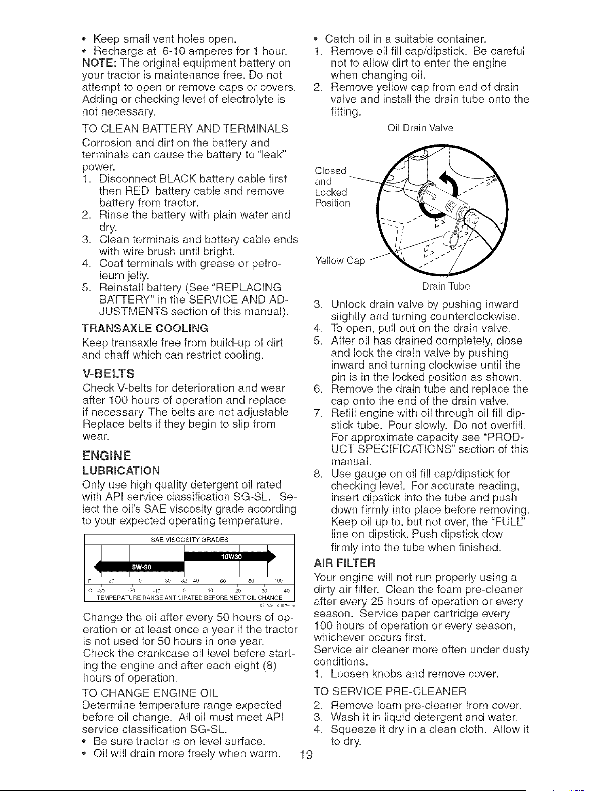
mMPORTANT: To ensure proper assembly,
center hole in blade must align with star
on mandrel assembly.
4. Reassemble blade bolt, lock washer
and flat washer in exact order as
shown.
5. Tighten blade bolt securely (27-35 Ft.
Lbs. torque).
H_PORTANT: Blade bolt is heat treated.
If bolt needs replacing, replace only with
approve bolt shown in the Repair Parts.
Trailing Edge Up Mandrel Assembly
F,atWasher f_ _jB,ade __
Lock
TO SHARPEN BLADE
NOTE: We do not recommend sharp-
ening blade - but if you do, be sure the
blade is balanced.
Care should be taken to keep the blade
balanced. An unbalanced blade will cause
excessive vibration and eventual damage
to mower and engine.
• The blade can be sharpened with a file
or on a grinding wheel. Do not attempt
to sharpen while on the mower.
• To check blade balance, you will need a
5/8" diameter steel bolt, pin, or a cone
balancer. (When using a cone balancer,
follow the instructions supplied with
balancer.)
NOTE: Do not use a nail for balancing
blade. The lobes of the center hole may
appear to be centered, but are not.
• Slide blade on to an unthreaded portion
of the steel bolt or pin and hold the
bolt or pin parallel with the ground. If
blade is balanced, it should remain in a
horizontal position. If either end of the
blade moves downward, sharpen the
heavy end until the blade is balanced.
5/8" Bolt or
Pin
Center Hole
BATTERY
Your tractor has a battery charging system
which is sufficient for normal use. How-
ever, periodic charging of the battery with
an automotive charger will extend its life.
• Keep battery and terminals clean.
18, Keep battery bolts tight.
• Keep small vent holes open.
Recharge at 6-10 amperes for 1 hour.
NOTE: The original equipment battery on
your tractor is maintenance free. Do not
attempt to open or remove caps or covers.
Adding or checking level of electrolyte is
not necessary.
TO CLEAN BATTERY AND TERMINALS
Corrosion and dirt on the battery and
terminals can cause the battery to "leak"
power.
1. Disconnect BLACK battery cable first
then RED battery cable and remove
battery from tractor.
2. Rinse the battery with plain water and
dry.
3. Clean terminals and battery cable ends
with wire brush until bright.
4. Coat terminals with grease or petro-
leum jelly.
5. Reinstall battery (See "REPLACING
BATTERY" in the SERVICE AND AD-
JUSTMENTS section of this manual).
TRANSAXLE COOUNG
Keep transaxle free from build-up of dirt
and chaff which can restrict cooling.
Check V-belts for deterioration and wear
after 100 hours of operation and replace
if necessary. The belts are not adjustable.
Replace belts if they begin to slip from
wear.
LUBRmCATmON
Only use high quality detergent oil rated
with API service classification SG-SL Se-
lect the oil's SAE viscosity grade according
to your expected operating temperature.
SAE VISCOSITY GRADES
F -20 0 30 32 40 60 80 100
c -_o -2o -1_ _ 1_ _o 3o 40
TEMPERATURE RANGE ANTICIPATED BEFORE NEXT OIL CHANGE
oil vJsccha_t4 e
Change the oil after every 50 hours of op-
eration or at least once a year if the tractor
is not used for 50 hours in one year.
Check the crankcase oil level before start-
ing the engine and after each eight (8)
hours of operation.
TO CHANGE ENGINE OIL
Determine temperature range expected
before oil change. All oil must meet API
service classification SG-SL
Be sure tractor is on level surface.
• Oil will drain more freely when warm.
• Catch oil in a suitable container.
1. Remove oil fill cap/dipstick. Be careful
not to allow dirt to enter the engine
when changing oil.
2. Remove yellow cap from end of drain
valve and install the drain tube onto the
fitting.
OH Drain VaUve
Closed
and
Locked
Position
Yellow Cap
Drain Tube
3. Unlock drain valve by pushing inward
slightly and turning counterclockwise.
4. To open, pull out on the drain valve.
5. After oil has drained completely, close
and lock the drain valve by pushing
inward and turning clockwise until the
pin is in the locked position as shown.
6. Remove the drain tube and replace the
cap onto the end of the drain valve.
7. Refill engine with oil through oil fill dip-
stick tube. Pour slowly. Do not overfill.
For approximate capacity see "PROD-
UCT SPECIFICATIONS" section of this
manual.
8. Use gauge on oil fill cap/dipstick for
checking level. For accurate reading,
insert dipstick into the tube and push
down firmly into place before removing.
Keep oil up to, but not over, the "FULL:'
line on dipstick. Push dipstick dow
firmly into the tube when finished.
AmR FmLTER
Your engine will not run properly using a
dirty air filter. Clean the foam pre-cleaner
after every 25 hours of operation or every
season. Service paper cartridge every
100 hours of operation or every season,
whichever occurs first.
Service air cleaner more often under dusty
conditions.
1. Loosen knobs and remove cover.
TO SERVICE PRE-CLEANER
2. Remove foam pre-cleaner from cover.
3. Wash it in liquid detergent and water.
4. Squeeze it dry in a clean cloth. Allow it
to dry.
19
5. Saturateit in engineoil. Wrap it in
clean, absorbentcloth and squeezeto
removeexcess oil.
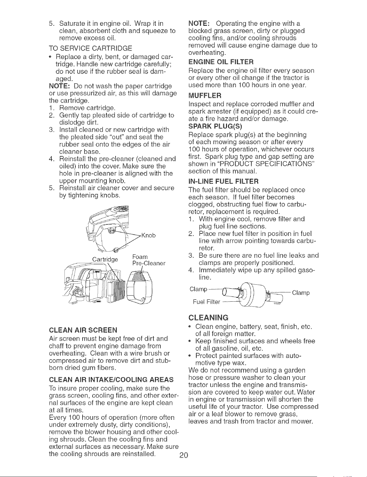
TO SERVICECARTRIDGE
Replacea dirty, bent,or damagedcar-
tridge. Handlenewcartridgecarefully;
do not use if the rubberseal is dam-
aged.
NOTE: Do not wash the papercartridge
or use pressurizedair, as this will damage
the cartridge.
1. Removecartridge.
2. Gentlytap pleatedside of cartridgeto
dislodgedirt.
3. Installcleaned or new cartridgewith
the pleatedside "out"and seat the
rubberseal onto the edges of the air
cleaner base.
4. Reinstallthe pre-cleaner(cleanedand
oiled) into the cover.Makesure the
hole in pre-cleaneris alignedwith the
uppermountingknob.
5. Reinstallair cleaner cover and secure
bytightening knobs.
.Knob
Cartridge Foam
Pre-CUeaner
NOTE: Operating the engine with a
blocked grass screen, dirty or plugged
cooling fins, and/or cooling shrouds
removed will cause engine damage due to
overheating.
ENGmNE OraL FmLTER
Replace the engine oil filter every season
or every other oil change if the tractor is
used more than 100 hours in one year.
MUFFLER
Inspect and replace corroded muffler and
spark arrester (if equipped) as it could cre-
ate a fire hazard and/or damage.
SPARK PLUG(S)
Replace spark plug(s) at the beginning
of each mowing season or after every
100 hours of operation, whichever occurs
first. Spark plug type and gap setting are
shown in "PRODUCT SPECIFICATIONS"
section of this manual.
mN-UNE FUEL FmLTER
The fuel filter should be replaced once
each season. If fuel filter becomes
clogged, obstructing fuel flow to carbu-
retor, rep{acement is required.
1. With engine cool, remove filter and
plug fuel line sections.
2. Place new fuel filter in position in fuel
line with arrow pointing towards carbu-
retor.
3. Be sure there are no fuel line leaks and
clamps are properly positioned.
4. Immediately wipe up any spilled gaso-
line.
Clamp ___ Clamp
Fuel Filter
CLEAN AmR SCREEN
Air screen must be kept free of dirt and
chaff to prevent engine damage from
overheating. Clean with a wire brush or
compressed air to remove dirt and stub-
born dried gum fibers.
CLEAN AmR mNTAKE/COOUNG AREAS
To insure proper cooling, make sure the
grass screen, cooling fins, and other exter-
nal surfaces of the engine are kept clean
at all times.
Every 100 hours of operation (more often
under extremely dusty, dirty conditions),
remove the blower housing and other cool-
ing shrouds. Clean the cooling fins and
external surfaces as necessary. Make sure
the cooling shrouds are reinstalled.
Clean engine, battery, seat, finish, etc.
of all foreign matter.
Keep finished surfaces and wheels free
of all gasoline, oil, etc.
Protect painted surfaces with auto-
motive type wax.
We do not recommend using a garden
hose or pressure washer to clean your
tractor unless the engine and transmis-
sion are covered to keep water out. Water
in engine or transmission will shorten the
useful life of your tractor. Use compressed
air or a leaf blower to remove grass,
leaves and trash from tractor and mower.
20
WARNmNG: TO AVOmD SERmOUS mNJURY, BEFORE PERFORMmNG ANY SER=
VmCE OR ADJUSTMENTS:
1. Depress clutch/brake pedal fully and set parking brake.
2. Place gearshift lever in neutral (N) position.
3. Place attachment clutch in "DISENGAGED" position.
4. Turn ignition key to "STOP" and remove key.
5. Make sure the blades and all moving parts have completely stopped.
6. Disconnect spark plug wire from spark plug and place wire where it cannot
come in contact with plug.
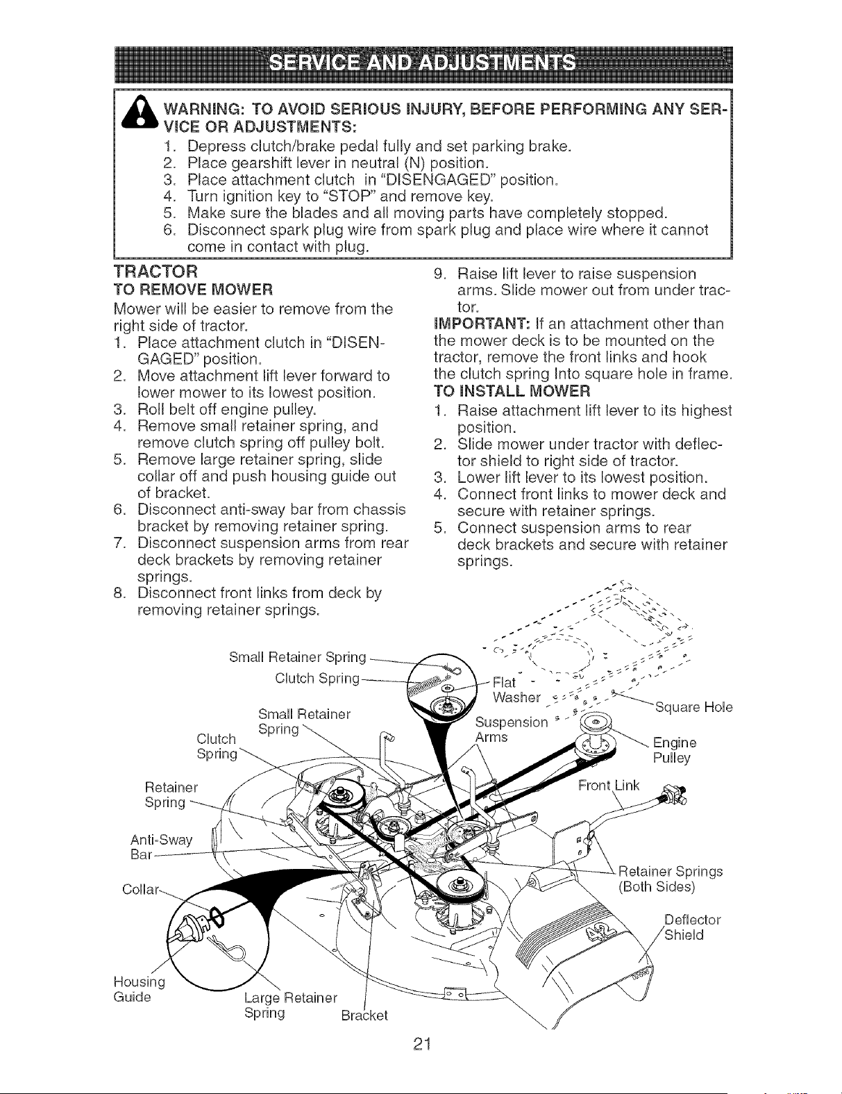
TRACTOR
TO REMOVE MOWER
Mower will be easier to remove from the
right side of tractor.
1. Place attachment clutch in "DISEN-
GAGED" position.
2. Move attachment lift lever forward to
lower mower to its lowest position.
3. Roll belt off engine pulley.
4. Remove small retainer spring, and
remove clutch spring off pulley bolt.
5. Remove large retainer spring, slide
collar off and push housing guide out
of bracket.
6. Disconnect anti-sway bar from chassis
bracket by removing retainer spring.
7. Disconnect suspension arms from rear
deck brackets by removing retainer
springs.
8. Disconnect front links from deck by
removing retainer springs.
Smal
Clutch S
Smal Retainer
Clutch
Spring_
9. Raise lift lever to raise suspension
arms. Slide mower out from under trac-
tor.
mMPORTANT: If an attachment other than
the mower deck is to be mounted on the
tractor, remove the front links and hook
the clutch spring Into square hole in frame.
TO I_STALL MOWER
1. Raise attachment lift lever to its highest
position.
2. Slide mower under tractor with deflec-
tor shield to right side of tractor.
3. Lower lift lever to its lowest position.
4. Connect front links to mower deck and
secure with retainer springs.
5. Connect suspension arms to rear
deck brackets and secure with retainer
springs.
\
Fiat __
Washer
Square Hole
Engine
Pulley
Retainer
Spring
Anti-Sway
Springs
(Both Sides)
Deflector
Housing
Guide
Large Retainer
Spring ;ket
21
6. Connect anti-sway bar to chassis
bracket and secure with retainer spring.
7. Push clutch cable housing guide into
bracket, slide collar onto guide and
secure with large retainer spring.
8. Place flat washer and clutch spring on
idler pulley bolt and secure with small
retainer spring.
9. Install belt onto engine pulley.
TO LEVEL MOWER HOUSING
Adjust the mower while tractor is parked
on level ground or driveway. Make sure
tires are properly inflated (See "PROD-
UCT SPECIFICATIONS" section of this
manual). If tires are over or underinflated,
you will not properly adjust your mower.
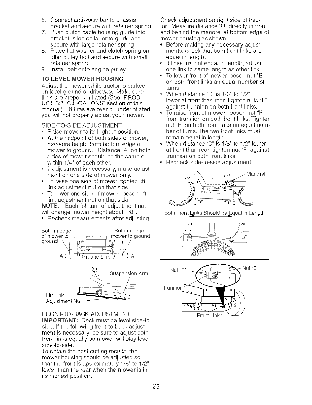
SIDE-TO-SIDE ADJUSTMENT
Raise mower to its highest position.
At the midpoint of both sides of mower,
measure height from bottom edge of
mower to ground. Distance "A" on both
sides of mower should be the same or
within 1/4" of each other.
If adjustment is necessary, make adjust-
ment on one side of mower only.
To raise one side of mower, tighten lift
link adjustment nut on that side.
To lower one side of mower, loosen lift
link adjustment nut on that side.
NOTE: Each full turn of adjustment nut
will change mower height about 1/8".
Recheck measurements after adjusting.
Bottom edge
Bottom edge of
Check adjustment on right side of trac-
tor. Measure distance "D" directly in front
and behind the mandrel at bottom edge of
mower housing as shown.
Before making any necessary adjust-
ments, check that both front links are
equal in length.
If links are not equal in length, adjust
one link to same length as other link.
To lower front of mower loosen nut "E"
on both front links an equal number of
turns.
When distance "D" is 1/8" to 1/2"
lower at front than rear, tighten nuts "F"
against trunnion on both front links.
To raise front of mower, loosen nut "F"
from trunnion on both front links. Tighten
nut "E" on both front links an equal num-
ber of turns. The two front links must
remain equal in length.
When distance "D" is 1/8" to 1/2" lower
at front than rear, tighten nut "F" against
trunnion on both front links.
Recheck side-to-side adjustment.
Oo\_ , oo, / MandreU
ii 01 _
o o o
Both Front Links ShouUd be uaUin Length
Arm
lu @ o,
Lift Link N_
Adjustment
FRONT-TO-BACK ADJUSTMENT
mMPORTANT: Deck must be level side-to
side. If the following front-to-back adjust-
ment is necessary, be sure to adjust both
front links equally so mower will stay level
side-to-side.
To obtain the best cutting results, the
mower housing should be adjusted so
that the front is approximately 1/8" to 1/2"
lower than the rear when the mower is in
its highest position.
Trunnion
22
Front Links
_E _
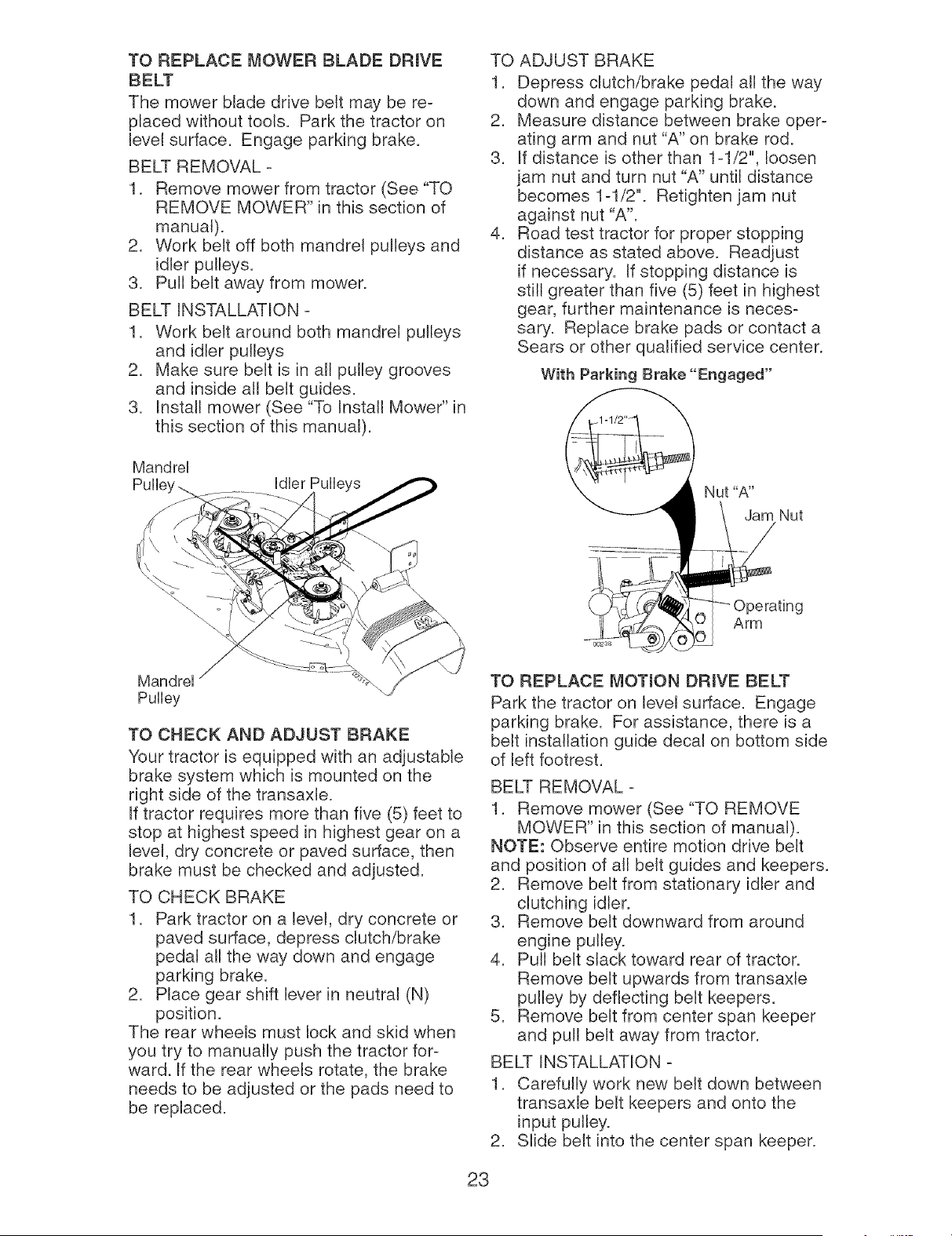
TO REPLACE _,_OWER BLADE DRmVE
BELT
The mower blade drive belt may be re-
placed without tools. Park the tractor on
level surface. Engage parking brake.
BELT REMOVAL -
1. Remove mower from tractor (See "TO
REMOVE MOWER" in this section of
manual).
2. Work belt off both mandrel pulleys and
idler pulleys.
3. Pull belt away from mower.
BELT INSTALLATION -
1. Work belt around both mandrel pulleys
and idler pulleys
2. Make sure belt is in all pulley grooves
and inside all belt guides.
3. Install mower (See "To Install Mower" in
this section of this manual).
TO ADJUST BRAKE
1. Depress clutch/brake pedal all the way
down and engage parking brake.
2. Measure distance between brake oper-
ating arm and nut "A" on brake rod.
3. If distance is other than 1-1/2", loosen
jam nut and turn nut "A" until distance
becomes 1-1/2". Retighten jam nut
against nut "A".
4. Road test tractor for proper stopping
distance as stated above. Readjust
if necessary. If stopping distance is
still greater than five (5) feet in highest
gear, further maintenance is neces-
sary. Replace brake pads or contact a
Sears or other qualified service center.
With Parking Brake "Engaged"
MandreU
Mandrel
Pulley
TO CHECK AND ADJUST BRAKE
Your tractor is equipped with an adjustable
brake system which is mounted on the
right side of the transaxle.
If tractor requires more than five (5) feet to
stop at highest speed in highest gear on a
level, dry concrete or paved surface, then
brake must be checked and adjusted.
TO CHECK BRAKE
1. Park tractor on a level, dry concrete or
paved surface, depress clutch/brake
pedal all the way down and engage
parking brake.
2. Place gear shift lever in neutral (N)
position.
The rear wheels must lock and skid when
you try to manually push the tractor for-
ward. If the rear wheels rotate, the brake
needs to be adjusted or the pads need to
be replaced.
TO REPLACE MOTION DRIVE BELT
Park the tractor on level surface. Engage
parking brake. For assistance, there is a
belt installation guide decal on bottom side
of left footrest.
BELT REMOVAL -
1. Remove mower (See "TO REMOVE
MOWER" in this section of manual).
NOTE: Observe entire motion drive belt
and position of all belt guides and keepers.
2. Remove belt from stationary idler and
clutching idler.
3. Remove belt downward from around
engine pulley.
4. Pull belt slack toward rear of tractor.
Remove belt upwards from transaxle
pulley by deflecting belt keepers.
5. Remove belt from center span keeper
and pull belt away from tractor.
BELT INSTALLATION -
1. Carefully work new belt down between
transaxb belt keepers and onto the
input pulley.
2. Slide belt into the center span keeper.
23
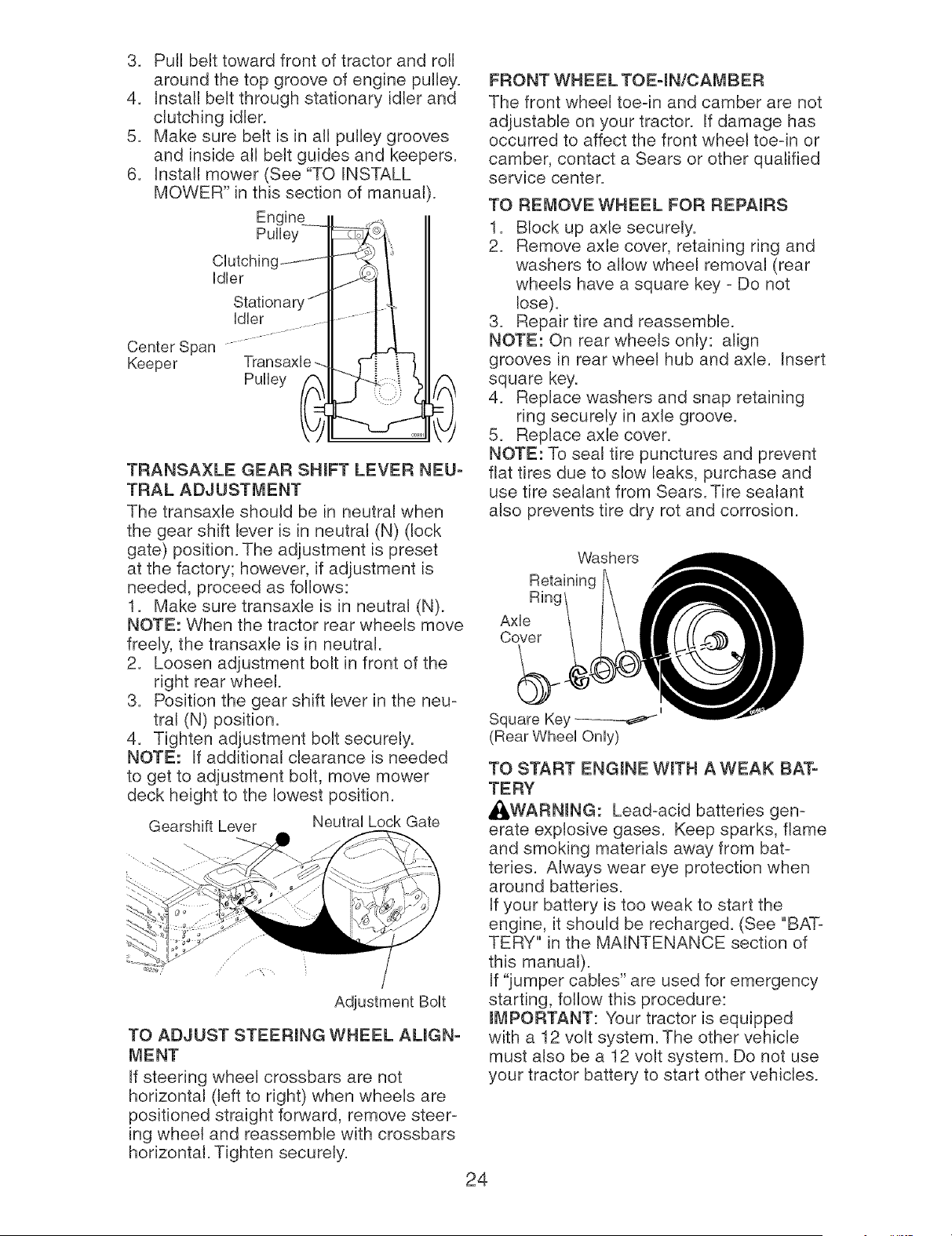
3. Pull belt toward front of tractor and roll
around the top groove of engine pulley.
4. Install belt through stationary idler and
clutching idler.
5. Make sure belt is in all pulley grooves
and inside all belt guides and keepers.
6. Install mower (See "TO INSTALL
MOWER" in this section of manual).
PuUUey
CUutcMng_ I
Idler
Stationary J_
Center Span
Keeper Transaxle --.
Pulley
TRANSAXLE GEAR SHmFT LEVER NEU-
TRAL ADJUSTMENT
The transaxle should be in neutral when
the gear shift lever is in neutral (N) (lock
gate) position. The adjustment is preset
at the factory; however, if adjustment is
needed, proceed as follows:
1. Make sure transaxle is in neutral (N).
NOTE: When the tractor rear wheels move
freely, the transaxle is in neutral.
2. Loosen adjustment bolt in front of the
right rear wheel.
3. Position the gear shift lever in the neu-
tral (N) position.
4. Tighten adjustment bolt securely.
NOTE: If additional clearance is needed
to get to adjustment bolt, move mower
deck height to the lowest position.
Gearshift Lever Neutral Lock Gate
/
Adjustment Bolt
TO ADJUST STEERmNG WHEEL AUGN-
_,_ENT
If steering wheel crossbars are not
horizontal (left to right) when wheels are
positioned straight forward, remove steer-
ing wheel and reassemble with crossbars
horizontal. Tighten securely.
FRONT WHEEL TOE-IN/CAMBER
The front wheel toe-in and camber are not
adjustable on your tractor. If damage has
occurred to affect the front wheel toe-in or
camber, contact a Sears or other qualified
service center.
TO REMOVE WHEEL FOR REPAmRS
1. Block up axle securely.
2. Remove axle cover, retaining ring and
washers to allow wheel removal (rear
wheels have a square key - Do not
lose).
3. Repair tire and reassemble.
NOTE: On rear wheels only: align
grooves in rear wheel hub and axle. Insert
square key.
4. Replace washers and snap retaining
ring securely in axle groove.
5. Replace axle cover.
NOTE: To seal tire punctures and prevent
flat tires due to slow leaks, purchase and
use tire sealant from Sears. Tire sealant
also prevents tire dry rot and corrosion.
Washers
Ring
Axle
Cover
I
Square Key
(Rear Wheel Only)
TO START ENGmNE WroTH A WEAK BAT-
TERY
_,WARNmNG: Lead-acid batteries gen-
erate explosive gases. Keep sparks, flame
and smoking materials away from bat-
teries. Always wear eye protection when
around batteries.
If your battery is too weak to start the
engine, it should be recharged. (See "BAT-
TERY" in the MAINTENANCE section of
this manual).
If "jumper cables" are used for emergency
starting, follow this procedure:
mMPORTANT: Your tractor is equipped
with a 12 volt system. The other vehicle
must also be a 12 volt system. Do not use
your tractor battery to start other vehicles.
24
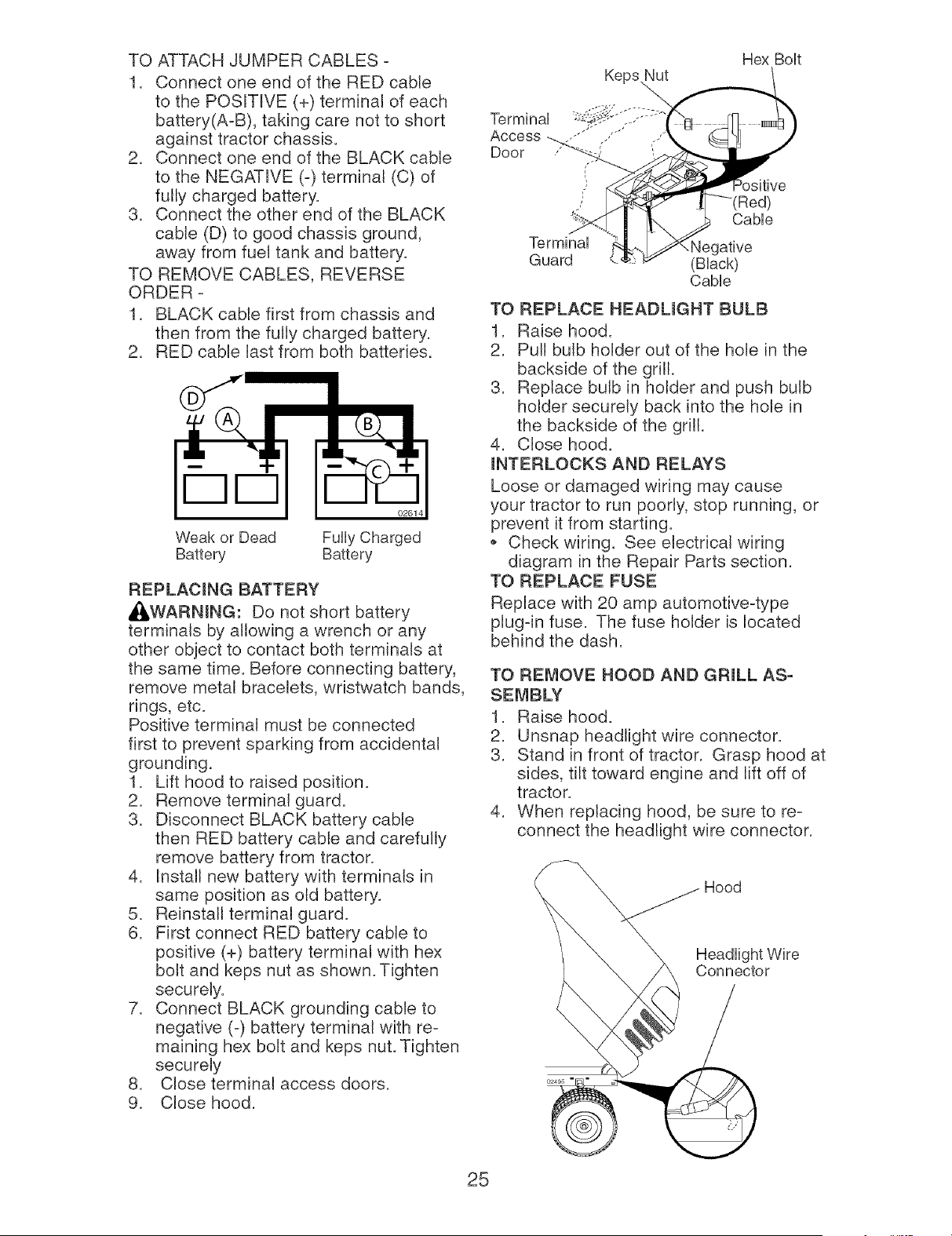
TO ATTACH JUMPER CABLES -
1. Connect one end of the RED cable
to the POSITIVE (+) terminal of each
battery(A-B), taking care not to short
against tractor chassis.
2. Connect one end of the BLACK cable
to the NEGATIVE (-) terminal (C) of
fully charged battery.
3. Connect the other end of the BLACK
cable (D) to good chassis ground,
away from fuet tank and battery.
TO REMOVE CABLES, REVERSE
ORDER -
1. BLACK cable first from chassis and
then from the fully charged battery.
2. RED cable last from both batteries.
02614
Weak or Dead FuUUyCharged
Battery Battery
REPLACING BATTERY
_WARNmNG: Do not short battery
terminals by allowing a 'wrench or any
other object to contact both terminals at
the same time. Before connecting battery,
remove metal bracelets, wristwatch bands,
rings, etc.
Positive terminal must be connected
first to prevent sparking from accidental
grounding.
1. Lift hood to raised position.
2. Remove terminal guard.
3. Disconnect BLACK battery cable
then RED battery cable and carefully
remove battery from tractor.
4. Install new battery with terminals in
same position as old battery.
5. Reinstall terminal guard.
6. First connect RED battery cable to
positive (+) battery terminal with hex
bolt and keps nut as shown. Tighten
securely.
7. Connect BLACK grounding cable to
negative (-) battery terminal with re-
maining hex bolt and keps nut. Tighten
securely
8. Close terminal access doors.
9. Close hood.
Keps Nut
Hex BoUt
Terminal
Access _,,,_'_.'< ,..'"
Door
t"
I
I"
Cable
Terminal Negative
Guard (Black)
Cable
TO REPLACE HEADUGHT BULB
1. Raise hood.
2. Pull bulb holder out of the hole in the
backside of the grill.
3. Replace bulb in holder and push bulb
holder securely back into the hole in
the backside of the grill.
4. Close hood.
mNTERLOCKS AND RELAYS
Loose or damaged wiring may cause
your tractor to run poorly, stop running, or
prevent it from starting.
* Check wiring. See electrical wiring
diagram in the Repair Parts section.
TO REPLACE FUSE
Replace with 20 amp automotive-type
piugqn fuse. The fuse holder is located
behind the dash.
TO REMOVE HOOD AND GRmLL AS-
SEMBLY
1. Raise hood.
2. Unsnap headlight wire connector.
3. Stand in front of tractor. Grasp hood at
sides, tilt toward engine and lift off of
tractor.
4. When replacing hood, be sure to re-
connect the headlight wire connector.
Headlight Wire
Connector
25
Maintenance, repair, or replacement of
the emission control devices and systems,
which are being done at the customers ex-
pense, may be performed by any non-road
engine repair establishment or individual.
Warranty repairs must be performed by an
authorized engine manufacturer's service
outlet.
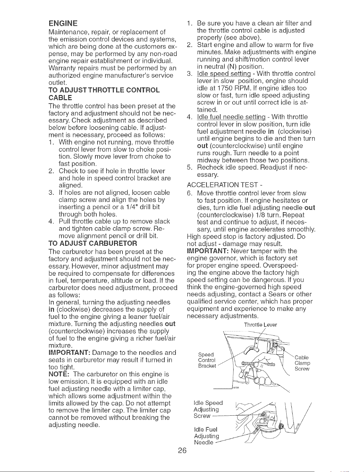
TO ADJUST THROTTLE CONTROL
CABLE
The throttle control has been preset at the
factory and adjustment should not be nec-
essary. Check adjustment as described
below before loosening cable. If adjust-
ment is necessary, proceed as follows:
1. With engine not running, move throttle
control lever from slow to choke posi-
tion. Slowly move lever from choke to
fast position.
2. Check to see if hole in throttle lever
and hole in speed control bracket are
aligned.
3. If holes are not aligned, loosen cable
clamp screw and align the holes by
inserting a pencil or a 1/4" drill bit
through both holes.
4. Pull throttle cable up to remove slack
and tighten cable clamp screw. Re-
move alignment pencil or drill bit.
TO ADJUST CARBURETOR
The carburetor has been preset at the
factory and adjustment should not be nec-
essary. However, minor adjustment may
be required to compensate for differences
in fuel, temperature, altitude or load. If the
carburetor does need adjustment, proceed
as follows:
In general, turning the adjusting needles
in (clockwise) decreases the supply of
fuel to the engine giving a leaner fuel/air
mixture. Turning the adjusting needles out
(counterclockwise) increases the supply
of fuel to the engine giving a richer fuel/air
mixture.
mMPORTANT: Damage to the needles and
seats in carburetor may result if turned in
too tight.
NOTE: The carburetor on this engine is
low emission. It is equipped with an idle
fuel adjusting needle with a Iimiter cap,
which allows some adjustment within the
limits allowed by the cap. Do not attempt
to remove the limker cap. The limiter cap
cannot be removed without breaking the
adjusting needle.
1. Be sure you have a clean air filter and
the throttle control cable is adjusted
properly (see above).
2. Start engine and allow to warm for five
minutes. Make adjustments with engine
running and shift/motion control lever
in neutral (N) position.
3. Idle speed setting - With throttle control
lever in slow position, engine shoutd
idle at 1750 RPM. If engine idles too
slow or fast, turn idle speed adjusting
screw in or out until correct idle is at-
tained.
4. Idle fuel needle setting - With throttle
control lever in slow position, turn idle
fuel adjustment needle in (clockwise)
until engine begins to die and then turn
out (counterclockwise) until engine
runs rough. Turn needle to a point
midway between those two positions.
5. Recheck idle speed. Readjust if nec-
essary.
ACCELERATION TEST -
6. Move throttle control lever from slow
to fast position. If engine hesitates or
dies, turn idle fuel adjusting needle out
(counterclockwise) 1/8 turn. Repeat
test and continue to adjust, if neces-
sary, until engine accelerates smoothly.
High speed stop is factory adjusted. Do
not adjust - damage may result.
mMPORTANT: Never tamper with the
engine governor, which is factory set
for proper engine speed. Overspeed-
ing the engine above the factory high
speed setting can be dangerous. If you
think the engine-governed high speed
needs adjusting, contact a Sears or other
qualified service center, which has proper
equipment and experience to make any
necessary adjustments.
Throttle Lever
Speed
Control
Bracket Clamp
Screw
26
Immediately prepare your tractor for stor-
age at the end of the season or if the trac-
tor will not be used for 30 days or more.
41_WARNING: Never store the tractor
with gasoline in the tank inside a building
where fumes may reach an open flame
or spark. Allow the engine to cool before
storing in any enclosure.
TRACTOR
Remove mower from tractor for winter
storage. When mower is to be stored for a
period of time, clean it thoroughly, remove
all dirt, grease, leaves, etc. Store in a
clean, dry area.
1. Clean entire tractor (See "CLEANING"
in the Maintenance section of this
manual).
2. Inspect and replace belts, if necessary
(See belt replacement instructions in
the Service and Adjustments section of
this manual).
3. Lubricate as shown in the Maintenance
section of this manual.
4. Be sure that all nuts, bolts and screws
are securely fastened. Inspect moving
parts for damage, breakage and wear.
Replace if necessary.
5. Touch up all rusted or chipped paint
surfaces; sand lightly before painting.
BATTERY
Fully charge the battery for storage.
,, After a period of time in storage, battery
may require recharging.
To help prevent corrosion and power
leakage during long periods of storage,
battery cables should be disconnected
and battery cleaned thoroughly (see "TO
CLEAN BATTERY AND TERMINALS" in
the Maintenance section of this manual).
After cleaning, leave cables discon-
nected and place cables where they
cannot come in contact with battery
terminals.
If battery is removed from tractor for
storage, do not store battery directly on
concrete or damp surfaces.
FUEL SYSTEM
mMPORTANT: It is important to prevent
gum deposits from forming in essential
fuel system parts such as carburetor, fuel
hose, or tank during storage. Also, alcohol
blended fuels (called gasohol or using
ethanol or methanol) can attract moisture
which leads to separation and formation of
acids during storage. Acidic gas can dam-
age the fuel system of an engine while in
storage.
Empty the fuel tank by starting the en-
gine and letting it run until the fuel lines
and carburetor are empty.
Never use engine or carburetor cleaner
products in the fuel tank or permanent
damage may occur.
Use fresh fuel next season.
NOTE: Fuel stabilizer is an acceptable
alternative in minimizing the formation of
fuel gum deposits during storage. Add
stabilizer to gasoline in fuel tank or stor-
age container. Always follow the mix ratio
found on stabilizer container. Run engine
at least 10 minutes after adding stabilizer
to allow the stabilizer to reach the car-
buretor. Do not empty the gas tank and
carburetor if using fuel stabilizer.
ENG(NE OIL
Drain oil (with engine warm) and replace
with clean engine oil. (See "ENGINE" in
the Maintenance section of this manual).
1. Remove spark plug(s).
2. Pour one ounce of oil through spark
plug hole(s) into cylinder(s).
3. Turn ignition key to start position for a
few seconds to distribute oil.
4. Replace with new spark plug(s).
OTHER
* Do not store gasoline from one season
to another.
Replace your gasoline can if your can
starts to rust. Rust and/or dirt in your
gasoline will cause problems.
If possible, store your tractor indoors
and cover it to give protection from dust
and dirt.
Cover your tractor with a suitable pro-
tective cover that does not retain mois-
ture. Do not use plastic. Plastic cannot
breathe which allows condensation to
form and will cause your tractor to rust.
mMPORTANT: Never cover tractor while
engine and exhaust areas are still warm.
27

TROUBLESHOOTmNG CHART:
See appropriate section in manuam unmess directed to Sears service center
PROBLEM
Wiii not start
Hard to start
Engine wiii not
turn over
Engine clicks but
wiii not start
CAUSE
1. Out of fuel.
2. Engine not "CHOKED"
properly.
3. Engine flooded.
4. Bad spark plug.
5. Dirty air filter.
6. Dirty fuel filter.
7 Water in fuel.
8. Loose or damaged wiring.
9. Carburetor out of adjustment.
10. Engine valves out of
adjustment.
1. Dirty air filter.
2. Bad spark plug.
3. Weak or dead battery.
4. Dirty fuel filter.
5. Stale or dirty fuel.
6. Loose or damaged wiring.
7. Carburetor out of adjustment.
8. Engine valves out of
adjustment.
1. Clutch/brake pedal not
depressed.
2. Attachment clutch is engaged.
3. Weak or dead battery.
4. Blown fuse.
5. Corroded battery terminals.
6. Loose or damaged wiring.
7. Faulty ignition switch.
8. Faulty solenoid or starter.
9. Faulty operator presence
switch(es).
1. Weak or dead battery.
2. Corroded battery terminals.
3. Loose or damaged wiring.
4. Faulty solenoid or starter.
CORRECTmON
1. Fill fuel tank.
2. See "TO START ENGINE"
in Operation section.
3. Wait several minutes
before attempting to start.
4. Replace spark plug.
5. Clean/replace air filter.
6. Replace fuel filter.
7. Empty fuel tank and carbure-
tor, refill tank with fresh gas-
oline and replace fuel filter.
8. Check all wiring.
9. See "To Adjust Carburetor"
in Service and Adjustments
section.
10. Contact a Sears or other
qualified service center.
1. Clean/replace air filter.
2. Replace spark plug.
3. Recharge or replace battery.
4. Replace fuel filter.
5. Empty fuel tank and refill tank
with fresh, clean gasoline.
6. Check all wiring.
7. See "To Adjust Carburetor"
in Service and Adjustments
section.
8. Contact a Sears or other
qualified service center.
1. Depress clutch/brake pedal.
2. Disengage attachment clutch.
3. Recharge or replace battery.
4. Replace fuse.
5. Clean battery terminals.
6. Check all wiring.
7. Check/replace ignition switch.
8. Check/replace solenoid or
starter.
9. Contact a Sears or other
qualified service center.
1. Recharge or replace battery.
2. Clean battery terminals.
3. Check atl wiring.
4. Check/replace solenoid or
starter.
28
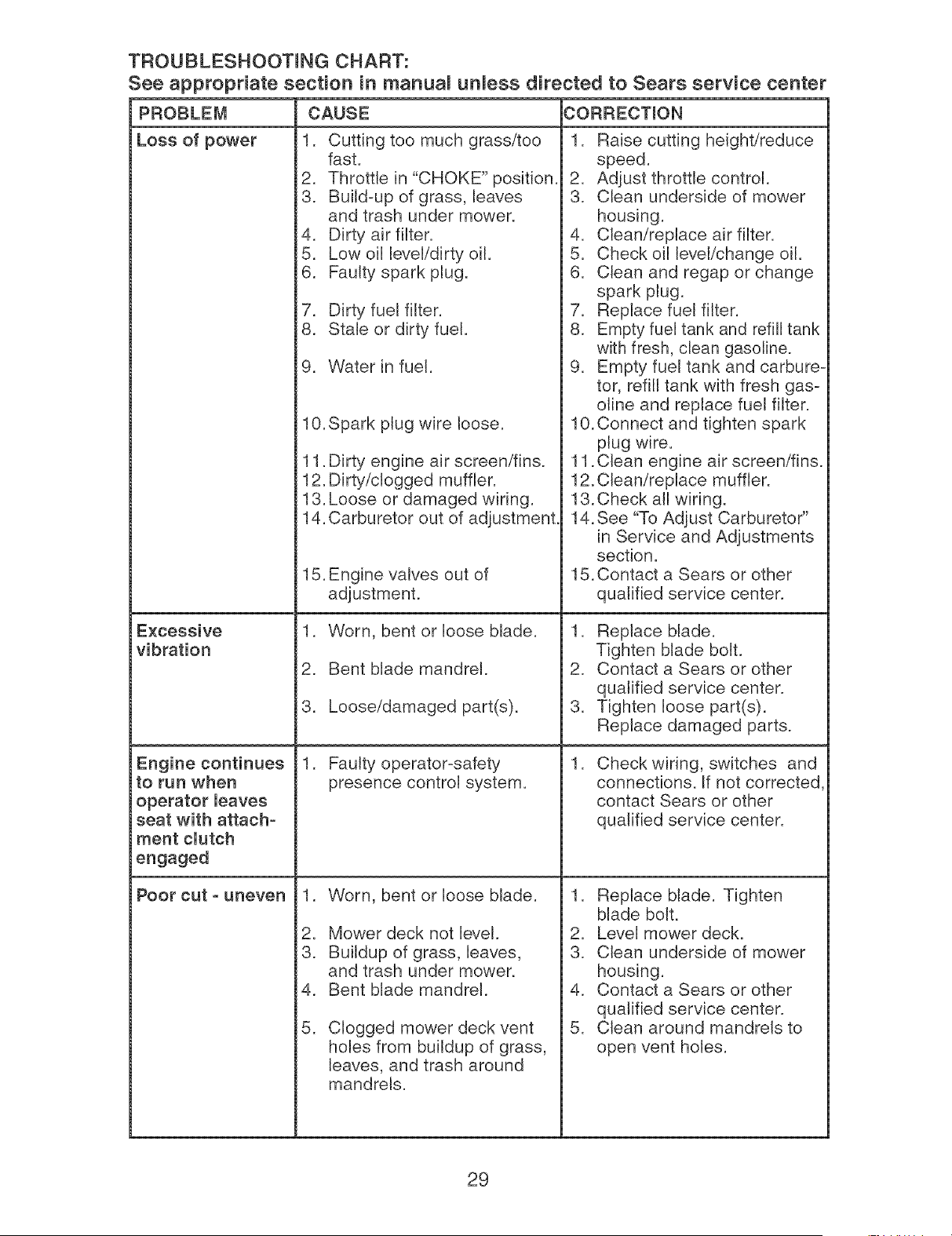
TROUBLESHOOTmNG CHART:
See appropriate section in manual unless directed to Sears service center
CAUSE CORRECTION
1.
1. Cutting too much grass/too
fast.
2. Throttle in "CHOKE" position.
3. Build=up of grass, [eaves
and trash under mower.
4. Dirty air filter.
5. Low oil level/dirty oil.
6. Faulty spark plug.
7. Dirty fuel filter.
8. Stale or dirty fuel.
PROBLEM
Loss of power
Excessive
vibration
Engine continues
to run when
operator leaves
seat with attach=
merit clutch
engaged
9. Water in fuel.
10.Spark plug wire loose.
11. Dirty engine air screen/fins.
12. Dirty/clogged muffler.
13. Loose or damaged wiring.
14. Carburetor out of adjustment
15. Engine valves out of
adjustment.
1. Worn, bent or loose blade.
2. Bent blade mandrel.
3. Loose/damaged part(s).
1. Faulty operator=safety
presence control system.
,
2.
3.
4.
5.
Worn, bent or loose blade.
Mower deck not level.
Buildup of grass, leaves,
and trash under mower.
Bent blade mandrel.
Clogged mower deck vent
holes from buildup of grass,
leaves, and trash around
mandrels.
POOr cut - uneven
Raise cutting height/reduce
speed.
2. Adjust throttle control.
3. Clean underside of mower
housing.
4. Clean/replace air filter.
5. Check oil level/change oil.
6. Clean and regap or change
spark plug.
7. Replace fuel filter.
8. Empty fuel tank and refill tank
with fresh, clean gasoline.
9. Empty fuel tank and carbure=
tor, refill tank with fresh gas=
oline and replace fuel filter.
10. Connect and tighten spark
plug wire.
11. Clean engine air screen/fins.
12. Clean/replace muffler.
13.Check all wiring.
14. See "To Adjust Carburetor"
in Service and Adjustments
section.
15. Contact a Sears or other
qualified service center.
1. Replace blade.
Tighten blade bolt.
2. Contact a Sears or other
qualified service center.
3. Tighten loose part(s).
Replace damaged parts.
,
Check wiring, switches and
connections. If not corrected
contact Sears or other
qualified service center.
1. Replace blade. Tighten
blade bolt.
2. Level mower deck.
3. Clean underside of mower
housing.
4. Contact a Sears or other
qualified service center.
5. Clean around mandrels to
open vent holes.
29
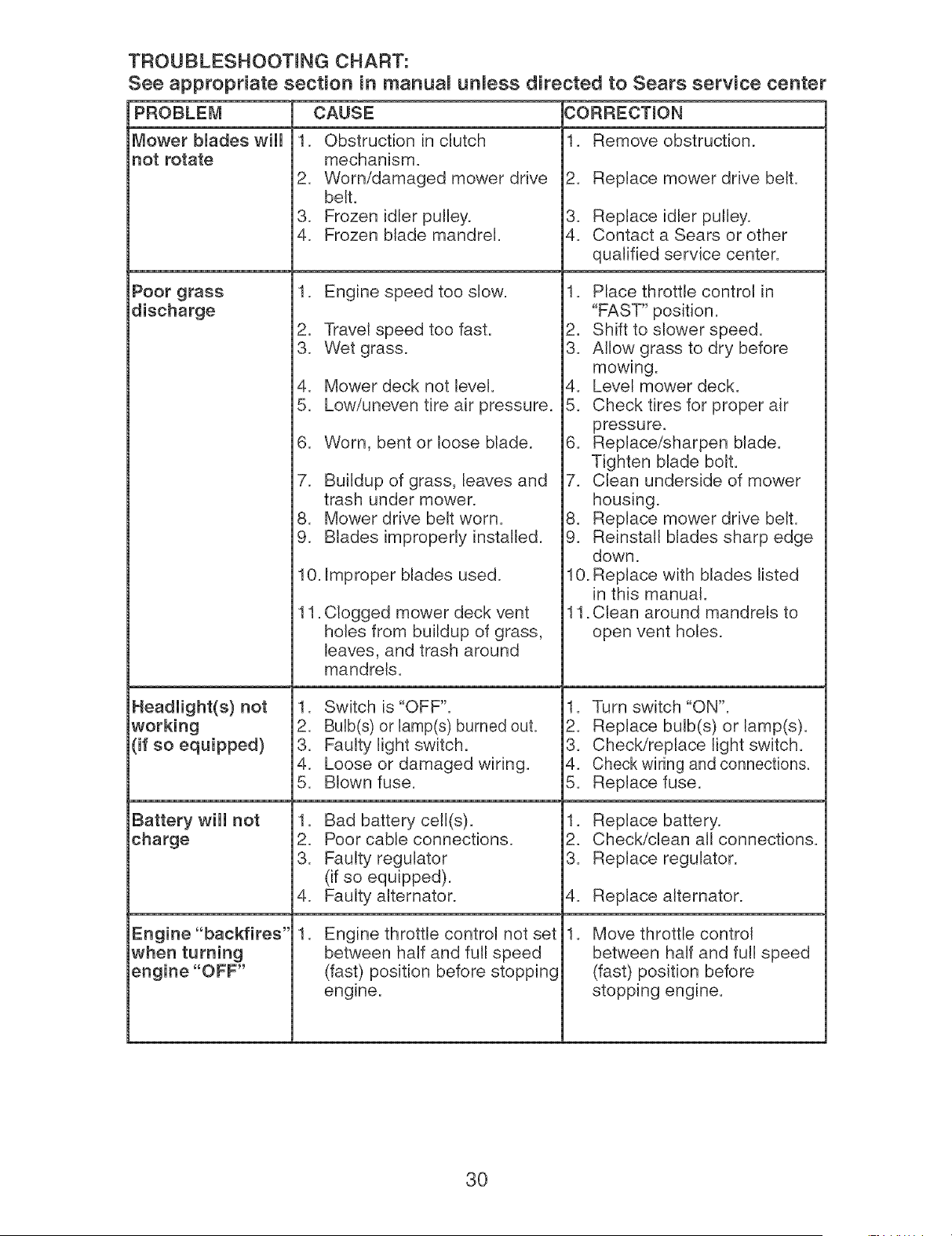
TROUBLESHOOTmNG CHART:
See appropriate section in marluamunmess directed to Sears service center
Mower blades wiii
not rotate
PROBLEi_I CAUSE CORRECTmON
1.
Poor grass
discharge
Headlight(s) not
working
(if so equipped)
Battery wiii not
charge
Engine "backfires"
when turning
engine "OFF"
1. Obstruction in clutch
mechanism.
2. Worn/damaged mower drive
belt.
3. Frozen idler pulley.
4. Frozen blade mandrel.
1. Engine speed too slow.
2. Travel speed too fast.
3. Wet grass.
4. Mower deck not level.
5. Low/uneven tire air pressure.
6. Worn, bent or loose blade.
7. Buildup of grass, leaves and
trash under mower.
8. Mower drive belt worn.
9. Blades improperly installed.
10. Improper blades used.
11
. Clogged mower deck vent
holes from buildup of grass,
leaves, and trash around
mandrels.
1. Switch is "OFF".
2. Bulb(s) or lamp(s) burned out.
3. Faulty light switch.
4. Loose or damaged wiring.
5. Blown fuse.
1. Bad battery cell(s).
2. Poor cable connections.
3. Faulty regulator
(if so equipped).
4. Faulty alternator.
.
Engine throttle control not set
between half and futl speed
(fast) position before stopping
engine.
.
Remove obstruction.
Replace mower drive belt.
3. Replace idler pulley.
4. Contact a Sears or other
qualified service center.
1. Place throttle control in
"FAST" position.
2. Shift to slower speed.
3. Allow grass to dry before
mowing.
4. Level mower deck.
5. Check tires for proper air
pressure.
6. Replace/sharpen blade.
Tighten blade bolt.
7. Clean underside of mower
housing.
8. Replace mower drive belt.
9. Reinstall blades sharp edge
down.
10. Replace with blades listed
in this manual.
11. Clean around mandrels to
open vent holes.
1. Turn switch "ON".
2. Replace bulb(s) or lamp(s).
3. Check/replace light switch.
4. Check wiring and connections.
5. Replace fuse.
1. Replace battery.
2. Check/clean all connections.
3. Replace regulator.
4. Replace alternator.
Move throttle control
between half and full speed
(fast) position before
stopping engine.
.
30
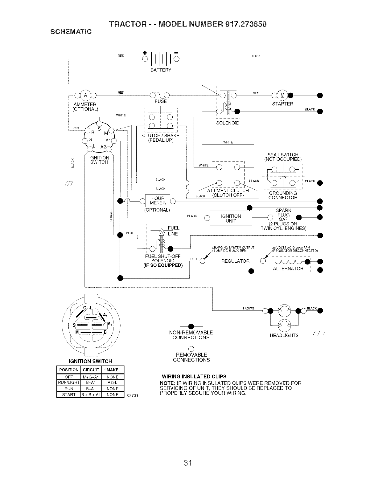
SCHEMATmC
TRACTOR - - MODEL NUMBER 917.273850
"I
sEo OII1 SLACK
BATTERY
CS_D
FUSE
I I
AMMETER
(OPTIONAL)
)G A1
IGNITION
SWITCH
RED
WHITE
J
................ _LUTCH / BRAK_E
(PEDAL UP)
BLACK
BLACK
(OPTIONAL)
SOLENOID
STARTER
BLACK
FUEL SHUT-OFF
SOLENOID
(IF SO EQUIPPED)
WHITE
__ SEAT SWITCH
(NOT OCCUPIED)
II ii i_ 1
I I _ I I
= I I
I f_, BLACK I I BLACK
( ATT'MENT CLUTCH _ _ i
SLACK CLUTCH OFF) , GROUNDING
CONNECTOR
1
SPARK 1
r
SLACK f_ IGNITION _ PLUG U
UNIT GAP w •
J (2 PLUGS ON
TWIN CYL ENGINES)
28 VOLTS AC @ 3600 RPM
..........
ALTERNATOR
CHARGING SYSTEM OUTPUT
15 AMP DC @ 3600 RPM
RED _[ REGULATOR
IGNITION SWITCH
POSITION CIRCUIT "MAKE"
OFF M+G+A1 NONE
RUN/LIGHT B+A1 A2+L
RUN B+A1 NONE
START B + S + A1 NONE
02731
NON-REMOVABLE
CONNECTIONS
O
REMOVABLE
CONNECTIONS
BROWN
WIRING INSULATED CLIPS
NOTE: IF WIRING INSULATED CLIPS WERE REMOVED FOR
SERVICING OF UNIT, THEY SHOULD BE REPLACED TO
PROPERLY SECURE YOUR WIRING.
31
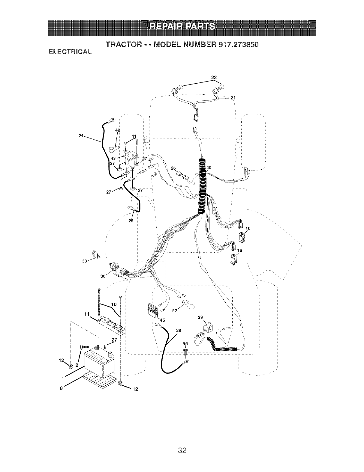
ELECTRmCAL
TRACTOR o o MODEL NUMBER 917.273850
11
\
29
12
i
i
i
i
\
32

ELECTRmCAL
TRACTOR o o MODEL NUMBER 917.273850
KEY PART
NO. NO. DESCRiPTiON
1 144927 Battery 12 Volt 35 AMP
2 74760412 Bolt Hex Hd 1/4-20 uric x 3/4
8 7603J Case Battery
10 145211 Bolt, Btr Front 1/4-20 x 7-1/2
11 150109 Holddown Battery Front Mount
12 145769 Nut, Push Nylon Battery Front 1/4
16 176138 Switch, Interlock Pushqn
21 183759 Harness Light Socket (W/4152j)
22 4152J Bulb Light #1156
24 4799J Cable Battery
25 146148 Cable Battery
26 175158 Fuse
27 73510400 Nut Keps Hex 1/4-20 unc
28 145491 Cable Ground
29 121305X Switch Seat
30 175566 Switch Ign
33 140403 Key Molded Craftsman
40 179720 Harness Ign
41 71110408 Bolt BIk= Fin Hex 1/4-20 unc x 1/2
42 131563 Cover Terminal
43 178861 Solenoid
45 122822X Ammeter Rectangular 15 Amp
52 141940 Protection Wire Loop
55 17490508 Screw Thdrol 5/16-18 x 1/2
NOTE:
All component dimensions given in U=S=
inches 1 inch = 25=4 mm
33
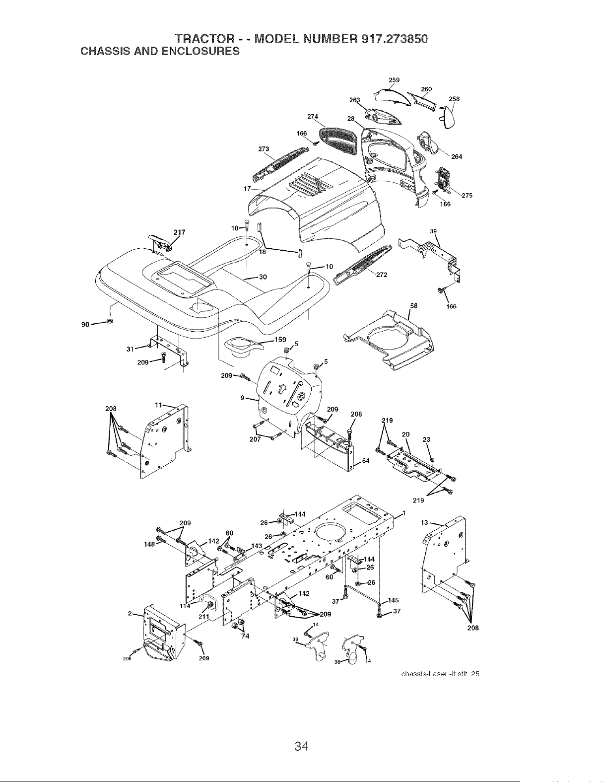
TRACTOR ° ° MODEL NUMBER 917.273850
CHASSmSAND ENCLOSURES
273
259
260
166
208
217
209
60
39
58 166
209
208
/
219
%
219
209
74
208
chassis-Laser-It.stlt 25
34

TRACTOR ooMODEL NUMBER 917.273850
CHASSmSAND ENCLOSURES
KEY PART
NO. NO. DESCRiPTiON
1 174619 Chassis Assembly
2 176554 Drawbar
3 17060612 Screw 3/8-16 x 3/4
5 155272 Bumper Hood/Dash
9 168337X013 Dash
10 STD533710 Bolt, Carriage 3/8-16 x 1
11 174996 Panel, Dash, LH=
13 172105X010 Panel, Dash, R.H=
14 17490608 ScrewThdroi 3/8-16 x 1/2
17 184272X615 Hood Assembly
18 184921 Bumper Hood
20 180679 Plate Mtg Battery Fuel Tank
23 124028X Bushing, Snap, Nylon, Fuel Line
26 STD541437 Locknut, Hex, with Insert 3/8-16 unc
28 184259 Grille/Lens Asm
30 179131X615 Fend/Ftrest
31 139976 Bracket, Fender Support
37 17490508 Screw ThdroJ 5/16-18 x 1/2
38 175710 Pivot Bracket Assembly
39 174714 Bracket Pivot
58 187154 Air Duct
60 STD533707 Bolt Rdhd Sqnk 3/8-16 uric x 3/4
64 154798 Dash Lower STLT
74 STD541437 Nut Crownlock 3/8-16 uric
90 124346X Nut Self-Thd Wsh-Hd 1/4
114 158112 Keeper Belt Rear Lh Stl
142 175702 Plate Reinforcement STLT
143 186689 Bracket Swaybar Chassis
144 175582 Bracket Pnt Footrest STLT
145 156524 Rod Pivot Chassis/Hood
148 17490620 ScrewThdrol 3/8-16 x 1-1/4
159 179950X428 Cupholder
166 171875 Screw Hwhd Hi-Lo #13-16 x 3/4
206 170165 Bolt Shoulder 5/16-18 TT
207 17670508 ScrewThdrol 5/16-18 x 1/2
208 17670608 ScrewThdrol 3/8-16 x 1/2
209 17000612 Screw Hex Wsh Thdr 3/8-16 x 3/4
211 145212 Nut Hexfiange Lock
217 179132X428 Console Fuel Window
219 17000512 Screw 5/16-18 x 3/4
258 184264X599 Lens Laser RH
259 184263X599 Lens Laser LH
260 184262X428 Cover Lens Laser
263 184265 Bezel Grille LH
264 184266 Bezel Grille RH
272 185925X428 Vent Hood RH
273 185924X428 Vent Hood LH
274 184260X428 insert Grille LH
275 184261X428 insert Grille RH
- - 5479J Plug BTN =359 Dia=
NOTE: AII component dimensions given in U. S.
inches 1 inch = 25.4 mm
35

TRACTOR ° - MODEL NUMBER 917.273850
GROUND DRIVE
57
\
212
70 116
.202
150
151
51
29
26
27
drive-fender.stlL26
$6

TRACTOR o o MODEL NUMBER 917.273850
GROUND DRmVE
KEY PART KEY PART
NO, NO, DESCRiPTiON NO, NO, DESCRiPTiON
1 Transaxle (See Breakdown) 62 8883R
Peerless 206-545C 63 175410
2 146682 Spring, Return, Brake 64 173937
3 123666X Pulley, Transaxle 65 STD551143
4 12000028 Ring, Retainer 66 154778
5 121520X Strap, Torque 70 134683
6 17000512 Screw 5/16-18 x 3/4 74 137057
8 165866 Rod Shifter Fender STLT 75 121749X
10 STD561210 Pin, Cotter 76 STD581075
11 105701X Washer, Shift Plate 77 123583X
13 74550412 Bolt 1/4-28 unfW/Patch Gr. 8 78 121748X
14 10040400 Washer Lock Hvy HelicaI 79 STD580025
15 74490544 Bolt Hex 5/16-18 Gr. 5 80 145090
16 73800500 Nut Lock Hx W/hs 5/16-18 81 165592
18 STD523710 Bolt Fin Hex 3/8-16 unc x 1 Gr. 5 82 165711
19 STD541437 Nut 83 19171216
21 106933X Knob 84 166231
22 130804 Rod, Brake 85 150360
24 STD541237 Nut 89 158391X428
25 106888X Spring, Brake Rod 90 124346X
26 STD551037 Washer 96 STD624003
27 STD561210 Pin 112 19091210
28 175765 Rod, Parking Brake 113 127285X
29 71673 Cap, Parking Brake 116 72140608
30 169592 Bracket, TransaxIe 120 73900600
32 STD523107 Bolt 150 175456
34 175578 Shaft Assembly, Foot Pedal 151 19133210
35 120183X Bearing, Nylon 156 166002
36 STD551062 Washer 158 165589
37 STD571810 Roll Pin 159 183900
38 179114 Pulley, Composite, Flat 161 72140406
39 72110622 Bolt 3/8-16 x 2-3/4 Gr. 5 162 73680400
41 175556 Keeper, Belt, Idler 163 74780416
47 127783 PulIey, Idler, V-Groove, PIastic 165 165623
48 154407 BelIcrank Clutch Grnd Drv Stl 166 17490510
49 123205X Retainer, Belt 168 165492
50 72110612 Bolt Cam Sh. 3/8-16 x 1-1/2 Gr. 5 169 165580
51 STD541437 Nut Crown Lock 3/8-16 uric 170 178394
52 STD541431 Nut Crown Lock 5/16-18 uric 197 169613
53 105710X Link, Clutch 198 169593
55 105709X Spring, Clutch Return 202 72110614
56 17060620 Screw 3/8-16 x 1-1/4 212 145212
57 130801 V-Belt, Ground Drive
59 169691 Keeper, Belt, Center Span
61 17120614 Screw 3/8-16 x .875
Cover, Pedal
Pulley, Engine
Bolt, Hex 7/16-20 x Gr. 5
Washer
Keeper, Belt, Engine, Fool-Proof
Guide, Mower Drive Belt, R.H.
Spacer, Axie
Washer 25/32 x 1-1/4 x 16 Ga.
E-Ring
Key, Square 2.0 x =1845/=1865
Washer 25/32 x 1-5/8 x 16 Ga.
Key Woodruff
Arm, Shift
Shaft Asm Cross Tapered 650 20
Spring, Torsion
Washer 17/32 x 3/4 x 16 Ga.
Link Transaxle
Nut, Nylock
Console, Shift, STLT
Nut, Self-Thding, Wsh Hd 1/4
Retainer Spring 1"
Washer 9/32 x 3/4 x 10 Ga.
Strap Torque 90 Degrees
Bolt Rdhd Sqneck 3/8-16 x 1
Nut Lock Fig. 3/8-16
Spacer Retainer
Washer 13/32 x 2 x 10 Ga.
Washer Srrted 5/16 ID x 1.125
Bracket Shift Mount
Hub Shift
Bolt Rdhd Sqnk 1/4-20 x 3/4 Gr.5
Nut Crownlock 1/4-20 unc
Bolt Hex Fin 1/4-20 uric x 1 Gr 5
Bracket Pivot Lever
Screw 5/16-18 x 5/8
Bolt Shoulder 5/16-18 x .561
Plate Fastening Lt
Keeper Belt Transaxle Gear
Nyliner Snapqn
Washer NyIiner
Bolt Carr. SH 3/8-16 x 1-3/4 Gr. 5
Nut Hex Hg. Lock
NOTE: All component dimensions given in U. S.
inches 1 inch = 25.4 mm
37
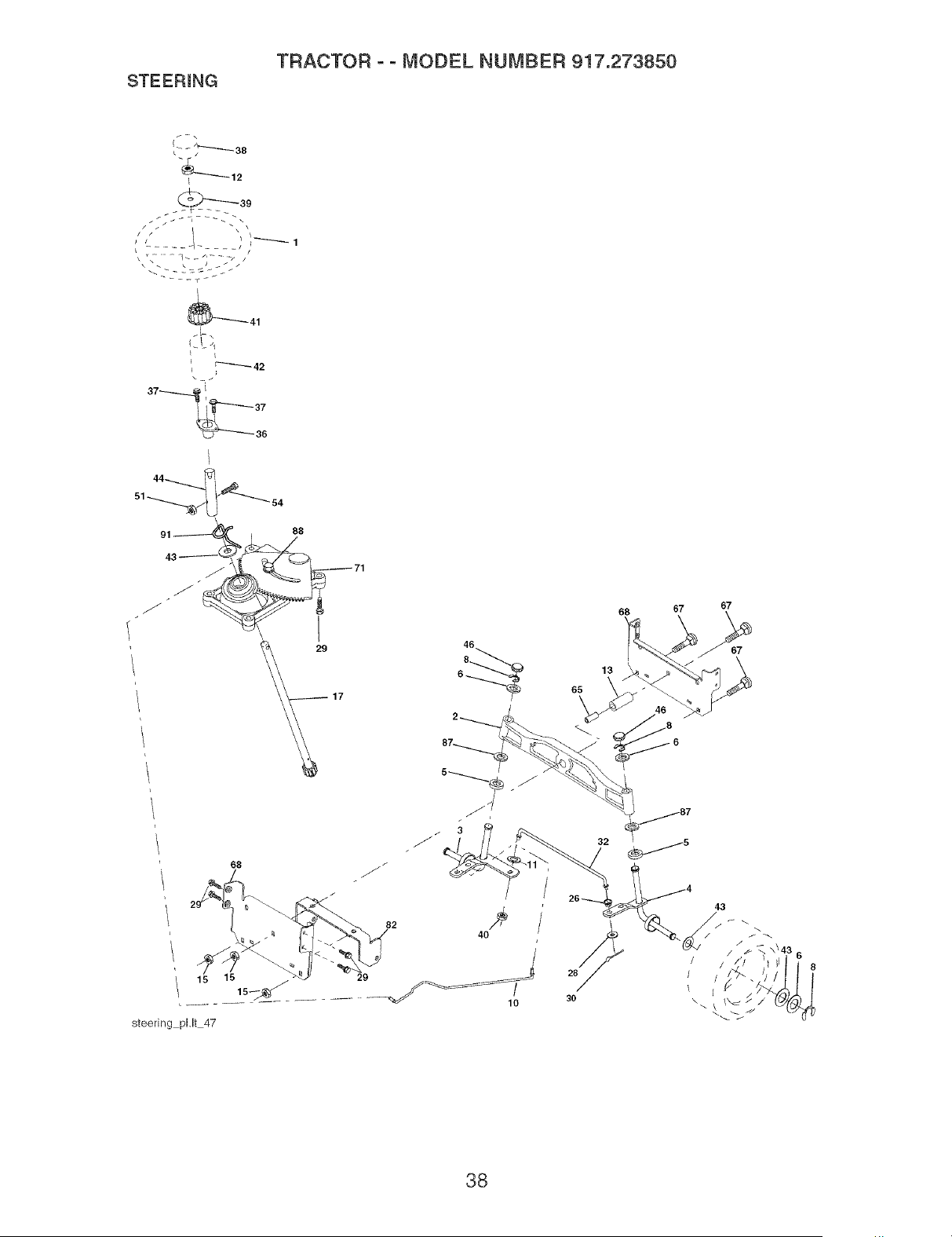
STEERmNG
TRACTOR ° ° MODEL NUMBER 917.273850
i _12
_39
L
37 . i
g143__, _j_ "_ 88 71
I
29
82
15 15 29
15_ ..............
steering pl,lt 47
46
/
10
13
os \
68 67
67
43
/ 6
/
! /
38

STEERmNG
TRACTOR o o MODEL NUMBER 917.273850
KEY PART
NO. NO. DESCRiPTiON
1 159944X428 Steering Wheel
2 184706 Axle Assembly
3 169840 Spindle Assembly, L.H.
4 169839 Spindle Assembly, R.H.
5 6266H Bearing, Race, Thrust, Hardened
6 121748X Washer 25/32 x 1-5/8 x 16 Ga.
8 12000029 Ring, Ktip
10 175121 Draglink
11 STD551137 Washer, Lock
12 73940800 Nut Hex Jam Toplock 1/2-20 uunf
13 136518 Spacer, Bearing, Axle
15 145212 Nut, Hexfiange Lock
17 180641 Shaft Assembly, Steering
26 126847X Bushing Link Drag
28 19131416 Washer 13/32 x 7/8 x 16 Ga.
29 17000612 Screw 3/8-16 x 3/4
30 76020412 Pin Cotter 1/8 x 3/4
32 130465 Rod, Tie
36 155099 Bushing, Steering
37 152927 Screw
38 159946X428 Insert, SteeringWhee!
39 19182411 Washer 9/16 IDx 1-1/2OD 11 Ga.
40 73540600 Nut, Crown!ock 3/8-24
41 159945 Adaptor, Steering Wheel
42 145054X428 Boot, Steering Shaft
43 121749X Washer 25/32 x 1-1/4 x 16 Ga.
44 180640 Extension Shaft Steering
46 184946X505 Cap, Spindle
51 73540400 Nut Crownlock 1/4-28
54 71130420 Bolt Hex 1/4-28 unf x 1-1/4 Gr. 8
65 160367 Spacer Brace Axle
67 72110618 Bolt RDHD SQNK 3/8-16 x 2-1/4
68 169827 Axte, Brace
71 175146 Steering Asm
82 169835 Bracket Susp Chassis Front
87 173966 Washer Fiat .781 x 1-1/2 x .14
88 175118 Bolt shoulder 7/16-20
91 175553 Clip Steering
NOTE: All component dimensions given in U. S.
inches 1 inch = 25.4 mm
39
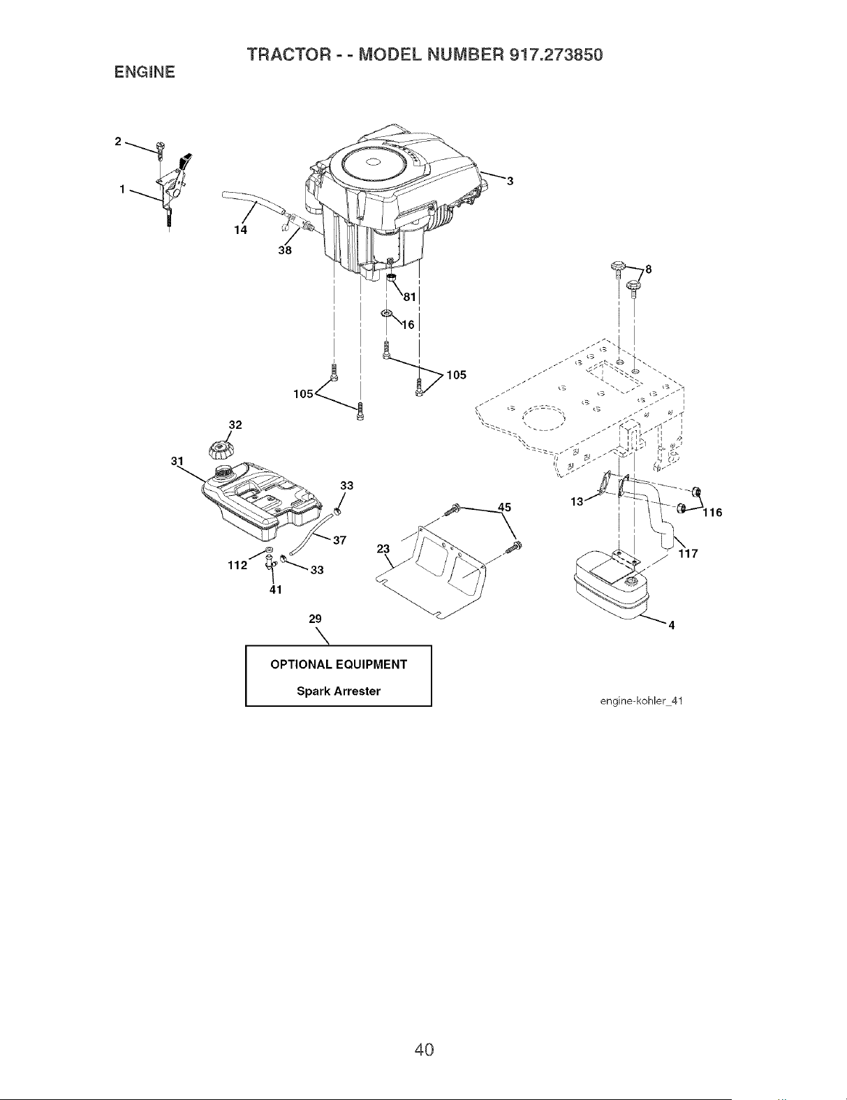
ENGINE
TRACTOR o o MODEL NUMBER 917.273850
2
1
14
38
lO5_
32
41
29
\
23
OPTIONAL EQUIPMENT
Spark Arrester
I
,105
engine-kohler 41
4O

ENGINE
TRACTOR o o MODEL NUMBER 917.273850
KEY PART
NO. NO. DESCRiPTiON
1 170548 Control, Throttle Paddle
2 17720408 Screw, Hex Thd Cut 1/4-20 x 1/2
3 Engine, Kohter, (See Breakdown) No=SV600-0001
4 188655 Muffler Exhaust
8 171877 Bolt 5/16-18 unc x 3/4 W/Sems
13 185909 Gasket, Muffler
14 148456 Tube Drain Oil Easy
16 STD551237 Washer Lock Ext Tooth 3/8
23 169837 Shield, Brn/Dbr Guard
29 137180 Arrestor, Spark
31 179022 Tank, FueI
32 179124X428 Cap Fuel
33 123487X Clamp, Hose
37 8543R Line, FueI
38 181654 Plug, Oil Drain Easy
41 139277 Stem Tank Fue!
45 17000612 Screw Hex Wsh 3/8-16 x 3/4
81 73510400 Nut Keps Hex 1/4-20 Starter Nut
105 17120616 Screw 3/8-16 x 1
112 3645J Bushing
116 184362 Nut Hex Flange Toplock M8-1=25
117 188654 Tube Exhaust
NOTE: All component dimensions given in U=S=
inches 1 inch = 25=4 mm
41
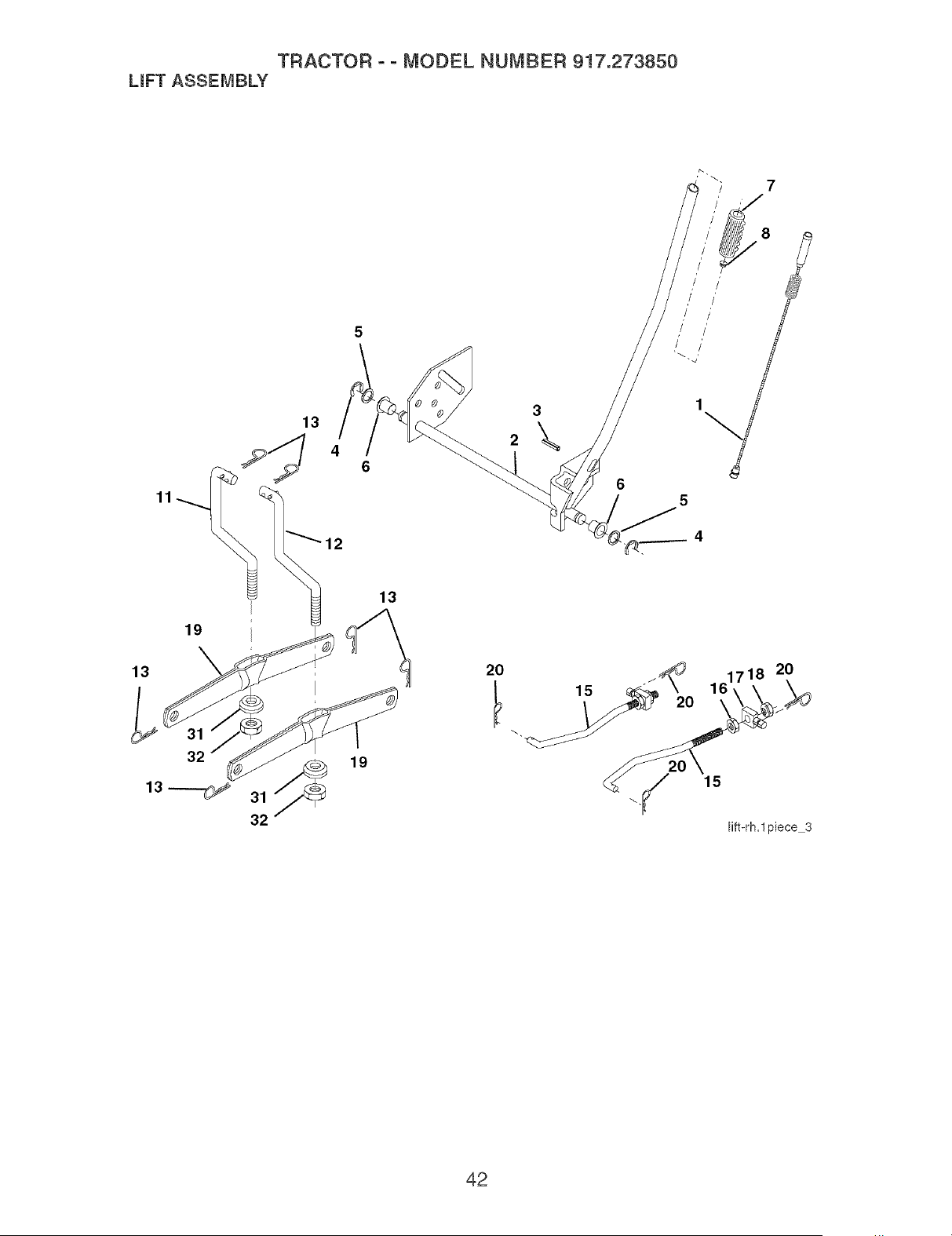
TRACTOR oo MODEL NUMBER 917.273850
LmFTASSEMBLY
19
13
13
6
5
13 20
32 _ 19 /
13 _ 31 \.
32
15
20
Fift-rh.l piece 3
42

TRACTOR ooMODEL NUMBER 917.273850
LmFTASSEMBLY
KEY PART
NO. NO. DESCRmPTmON
1 159460 Wire Asm Hnner/Sprg
W/plunger LT
2 159471 Shaft Asm Lift RH w/hf
3 105767X Pin Groove 1 500 Zinc
4 12000002 E Ring #5133-62
5 19211621 Washer 21/32 x 1 x21 Ga.
6 120183X Bearing Nylon BIk 629 Hd
7 125631X Grip Handle
8 122365X Button PIunger Yellow
11 139865 Link Lift LH Fixed Length
12 139866 Link Lift RH Fixed Length
13 4939M Retainer Spring
15 173288 Link Front
16 73350800 Nut Jam Hex 1/2-13 uric
17 175689 Trunnion BIk Zinc
18 73800800 Nut Lock w/Wsh 1/2-13 unc
19 139868 Arm Suspension Rear
20 163552 Retainer Spring
31 169865 Bearing Pvt Lift
32 73540600 Nut Crownlock 3/8 - 24
NOTE: All component dimensions given in U. S.
inches 1 inch = 25.4 mm
43
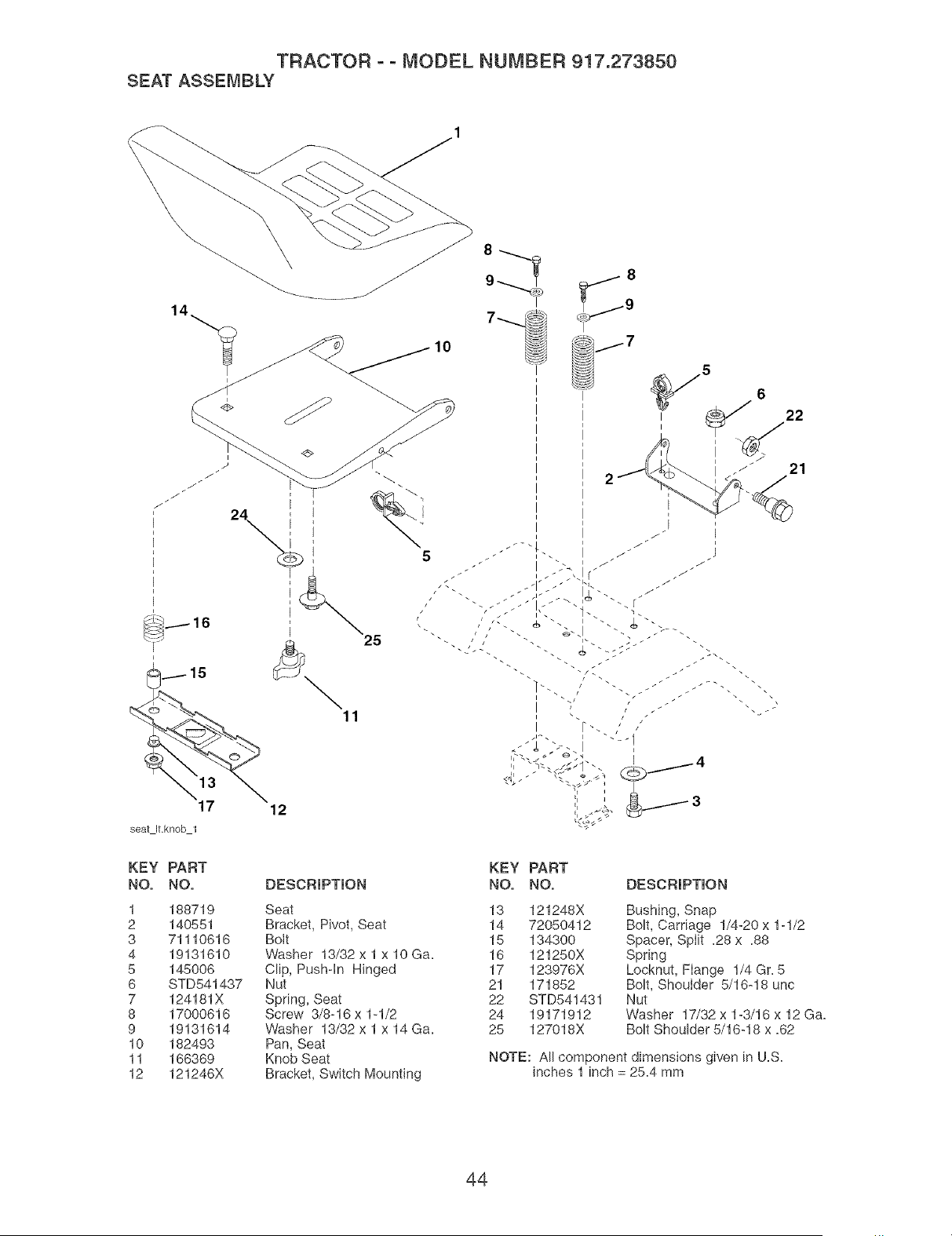
TRACTOR o o MODEL NUMBER 917.273850
SEAT ASSEMBLY
÷
i
E
24 ' !
25
11
5
/
//
r
17
seat Itknob 1
KEY PART
NO, NO,
1 188719
2 140551
3 71110616
4 19131610
5 145006
6 STD541437
7 124181X
8 17000616
9 19131614
10 182493
11 166369
12 121246X
12
DESCRIPTION
Seat
Bracket, Pivot, Seat
Bolt
Washer 13/32 x 1 x 10 Ga.
Clip, Push-in Hinged
Nut
Spring, Seat
Screw 3/8-16 x 1-1/2
Washer 13/32 x 1 x 14 Ga.
Pan, Seat
Knob Seat
Bracket, Switch Mounting
i
I
i
I
i
I
i
I
i
I
i
i Z
_J
/
.,!
El _ 3
E ×
KEY PART
NO. NO. DESCRIPTION
13 121248X Bushing, Snap
14 72050412 Bolt, Carriage 1/4-20 x 1-1/2
15 134300 Spacer, Split =28 x =88
16 121250X Spring
17 123976X Locknut, Flange 1/4 Gr. 5
21 171852 Bolt, Shoulder 5/16-18 unc
22 STD541431 Nut
24 19171912 Washer 17/32 x 1-3/16 x 12 Ga=
25 127018X Bolt Shoulder 5/16-18 x =62
NOTE: All component dimensions given in U.S.
inches 1 inch = 25.4 mm
44
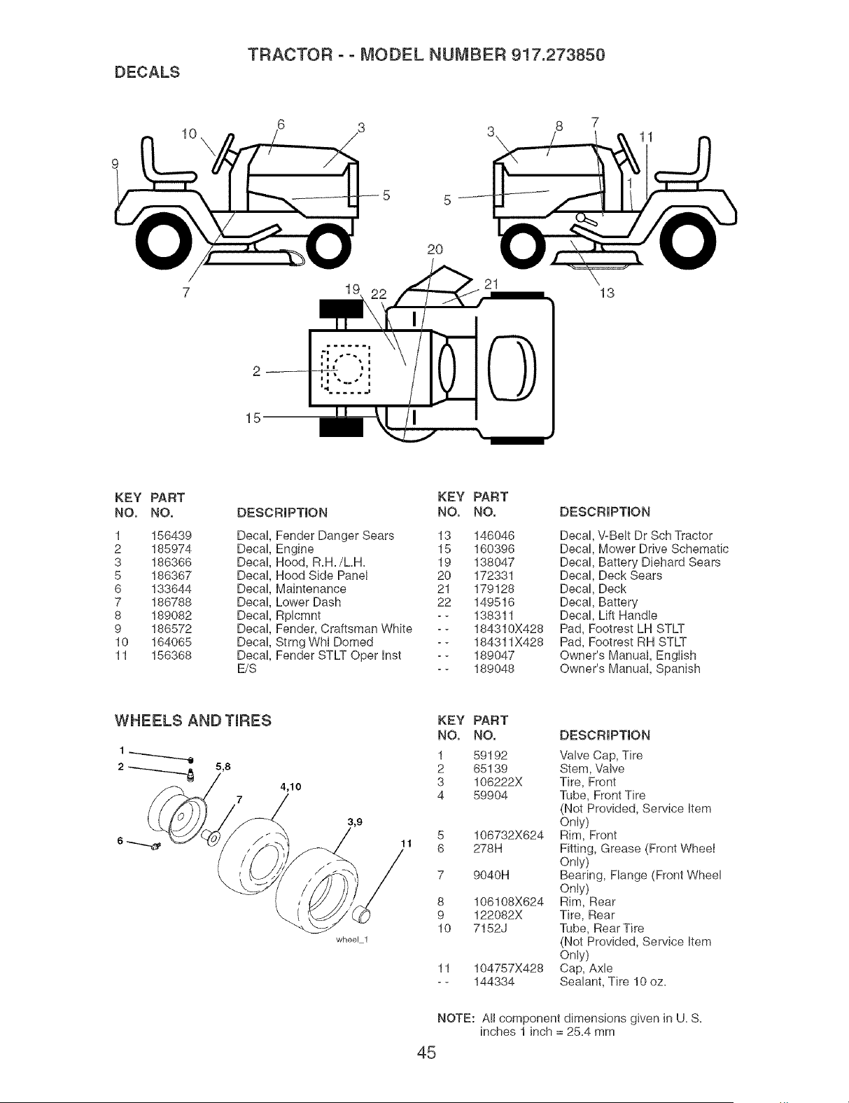
DECALS
TRACTOR o o MODEL NUMBER 917.273850
10
8 7
11
15
2O
13
KEY PART
NO, NO, DESCRIPTION
1 156439
2 185974 Decal
3 186366 Decal
5 186367 Decal
6 133644 Decal
7 186788 Decal
8 189082 Decal
9 186572 Decal
10 164065 Decal
11 156368 Decal
E/S
Decal Fender Danger Sears
KEY PART
NO. NO.
13 146046
Engine 15 160396
Hood, R.H./LH. 19 138047
Hood Side Panel 20 172331
Maintenance 21 179128
Lower Dash 22 149516
Rplcmnt - - 138311
Fender, Craftsman White - - 184310X428
Strng Whl Domed - - 184311X428
Fender STLT Oper Inst - - 189047
- - 189048
DESCRIPTION
Decal, V-Belt Dr Sch Tractor
Decal, Mower Drive Schematic
Decal, Battery Diehard Sears
Decal, Deck Sears
Decal, Deck
Decal, Battery
Decal, Lift Handle
Pad, Footrest LH STLT
Pad, Footrest RH STLT
Owner's Manual, English
Owner's Manual, Spanish
WHEELS AND TmRES
5,8
7
4,10
wheel 1
11
KEY PART
NO, NO,
1 59192
2 65139
3 106222X
4 59904
106732X624
278H
9040H
8 106108X624
9 122082X
10 7152J
11 104757X428
-- 144334
DESCRIPTION
Valve Cap, Tire
Stem, Valve
Tire, Front
Tube, Front Tire
(Not Provided, Service Item
Only)
Rim, Front
Fitting, Grease (Front Wheel
Only)
Bearing, Flange (Front Wheel
Only)
Rim, Rear
Tire, Rear
Tube, Rear Tire
(Not Provided, Service item
Only)
Cap, Axle
Sealant, Tire 10 oz.
NOTE: A!I component dimensions given in U. S.
inches 1 inch = 25.4 mm
45
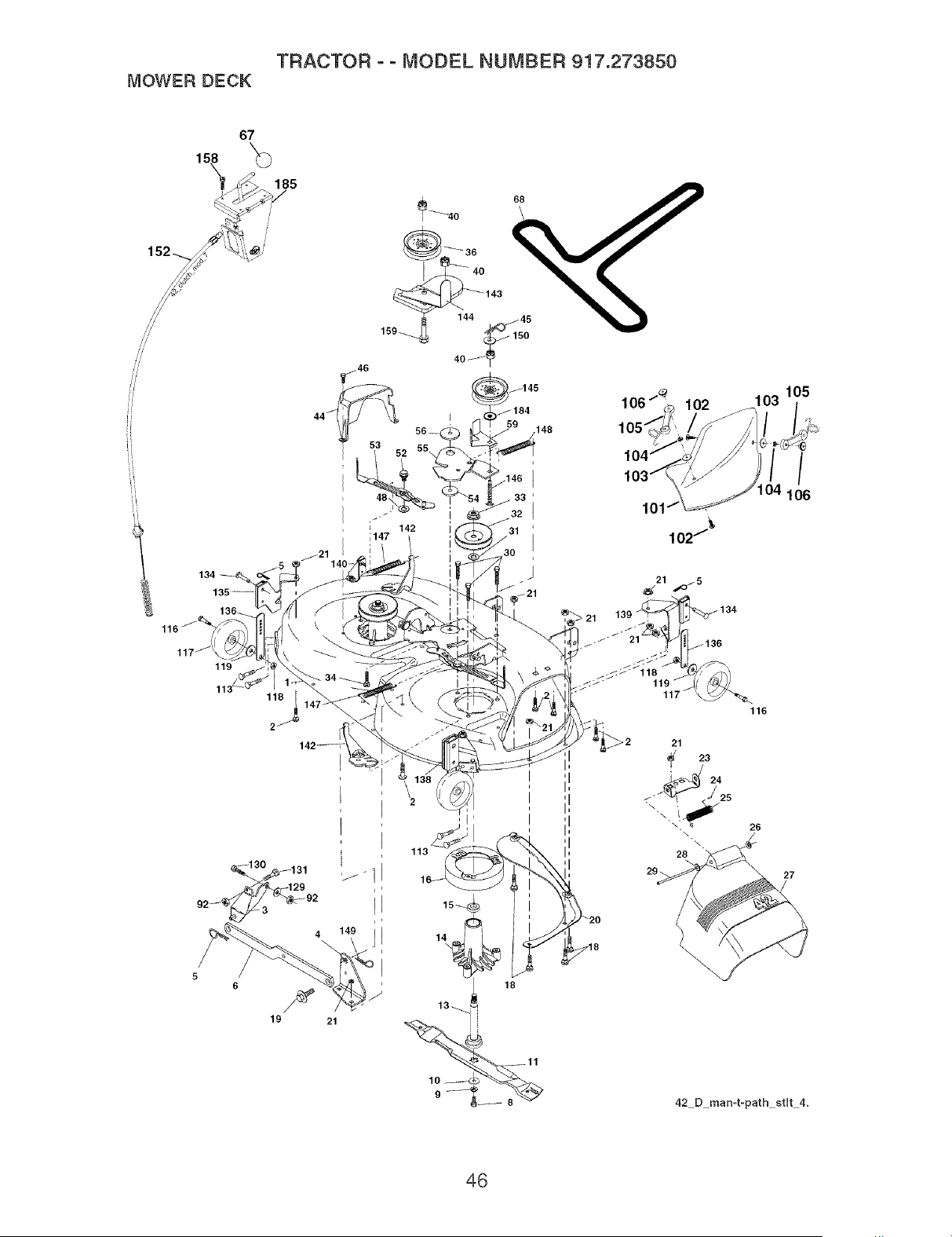
TRACTOR - - MODEL NUMBER 917.273850
MOWER DECK
67
119
118
6
f
19
148
48, 33
I
142
;147 I
loo-_lo2 lo3lo5
,o,c;,__-_]-i/b--,
lO4_
\" _104 106
102/_
42 D man=t-path atlt 4.
46
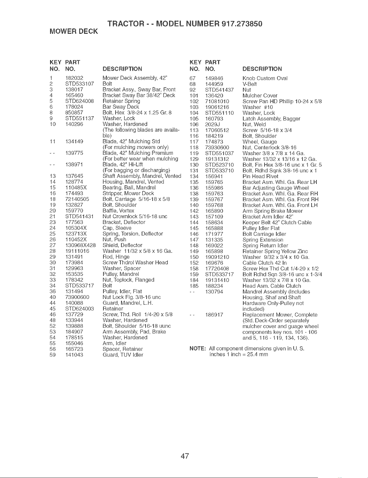
TRACTOR ° ° MODEL NUMBER 917.273850
MOWER DECK
KEY PART KEY PART
NO. NO. DESCRIPTION NO. NO.
1 182032 Mower Deck Assembly, 42" 67 149846
2 STD533107 Bolt 68 144959
3 138017 Bracket Assy, Sway Bar, Front 92 STD541437
4 165460 Bracket Sway Bar 38/42" Deck 101 136420
5 STD624008 Retainer Spring 102 71081010
6 178024 Bar Sway Deck 103 19061216
8 850857 Bolt, Hex 3/8-24 x 1.25 Gr. 8 104 STD551110
9 STD551137 Washer, Lock 105 160793
10 140296 Washer, Hardened 106 2029J
(The folIowing blades are availa- 113 17060512
bIe) 116 184219
11 134149 Biade, 42" Mulching Std 117 174873
(For mulching mowers only) 118 73930600
- - 139775 Blade, 42" Mulching Premium 119 STD551037
(For better wear when mulching 129 19131312
- - 138971 Biade, 42" Hi-Lift 130 STD523710
(For bagging or discharging) 131 STD533710
13 137645 Shaft Assembly, Mandrel, Vented 134 156941
14 128774 Housing, Mandrel, Vented 135 159765
15 110485X Bearing, Bal!, Mandrel 136 155986
16 174493 Stripper, Mower Deck 138 159763
18 72140505 Bott, Carriage 5/16-18 x 5/8 139 159767
19 132827 Bolt, Shoulder 140 159768
20 159770 Baffle, Vortex 142 165890
21 STD541431 Nut Crownlock 5/16-18 unc 143 157109
23 177563 Bracket, Deflector 144 158634
24 105304X Cap, Sleeve 145 165888
25 123713X Spring, Torsion, Deflector 146 171977
26 110452X Nut, Push 147 131335
27 130968X428 Shield, Deflector 148 169022
28 19111016 Washer 11/32x5/8x16Ga. 149 165898
29 131491 Rod, Hinge 150 19091210
30 173984 Screw ThdroI Washer Head 152 169676
31 129963 Washer, Spacer 158 17720408
32 153535 Pulley, Mandrel 159 STD533717
33 178342 Nut, Topiock, Flanged 184 19131410
34 STD533717 Bolt 185 188234
36 131494 PulIey, Idler, Fiat -- 130794
40 73900600 Nut Lock Hg. 3/8-16 uric
44 140088 Guard, Mandrel, L.H.
45 STD624003 Retainer
46 137729 Screw, Thd. Roll 1/4-20 x 5/8 - - 186917
48 133944 Washer, Hardened
52 139888 Bolt, Shoulder 5/16-18 uunc
53 184907 Arm Assembly, Pad, Brake
54 178515 Washer, Hardened
55 155046 Arm, Idler
56 165723 Spacer, Retainer
59 141043 Guard, TUV Idler
DESCRIPTION
Knob Custom Oval
V-Belt
Nut
Mulcher Cover
Screw Pan HD Phillip 10-24 x 5/8
Washer #10
Washer, Lock
Latch Assembly, Bagger
Nut, Weld
Screw 5/16-18 x 3/4
Bolt, Shoulder
Whee!, Gauge
Nut, Centerlock 3/8-16
Washer 3/8 x 7/8 x 14 Ga.
Washer 13/32 x 13/16 x 12 Ga.
Bolt, Fin Hex 3/8-16 unc x 1 Gr. 5
Bolt, Rdhd Sqnk 3/8-16 uric x 1
Pin Head Rivet
Bracket Asm. WhL Ga. Rear LH
Bar Adjusting Gauge Wheel
Bracket Asm. WhL Ga. Rear RH
Bracket Asm. WhL Ga. Front RH
Bracket Asm. WhI. Ga. Front LH
Arm Spring Brake Mower
Bracket Arm Idler 42"
Keeper Belt 42" Clutch Cable
Pulley Idler Fiat
Bolt Carriage Idler
Spring Extension
Spring Return Idler
Retainer Spring Yellow Zinc
Washer 9/32 x 3/4 x 10 Ga.
Cable Clutch 42 In
Screw Hex Thd Cut 1/4-20 x 1/2
Bolt Rdhd Sqn 3/8-16 unc x 1-3/4
VVasher 13/32 x 7/8 x 10 Ga.
Head Asm. Cable Clutch
Mandrel Assembly (Includes
Housing, Shaf and Shaft
Hardware Only-Pulley not
included)
Replacement Mower, Complete
(Std. Deck-Order separately
mulcher cover and guage wheel
components key nos. 101 - 106
and 5, 116- 119, 134, 136).
NOTE: All component dimensions given in U. S.
inches 1 inch = 25.4 mm
47
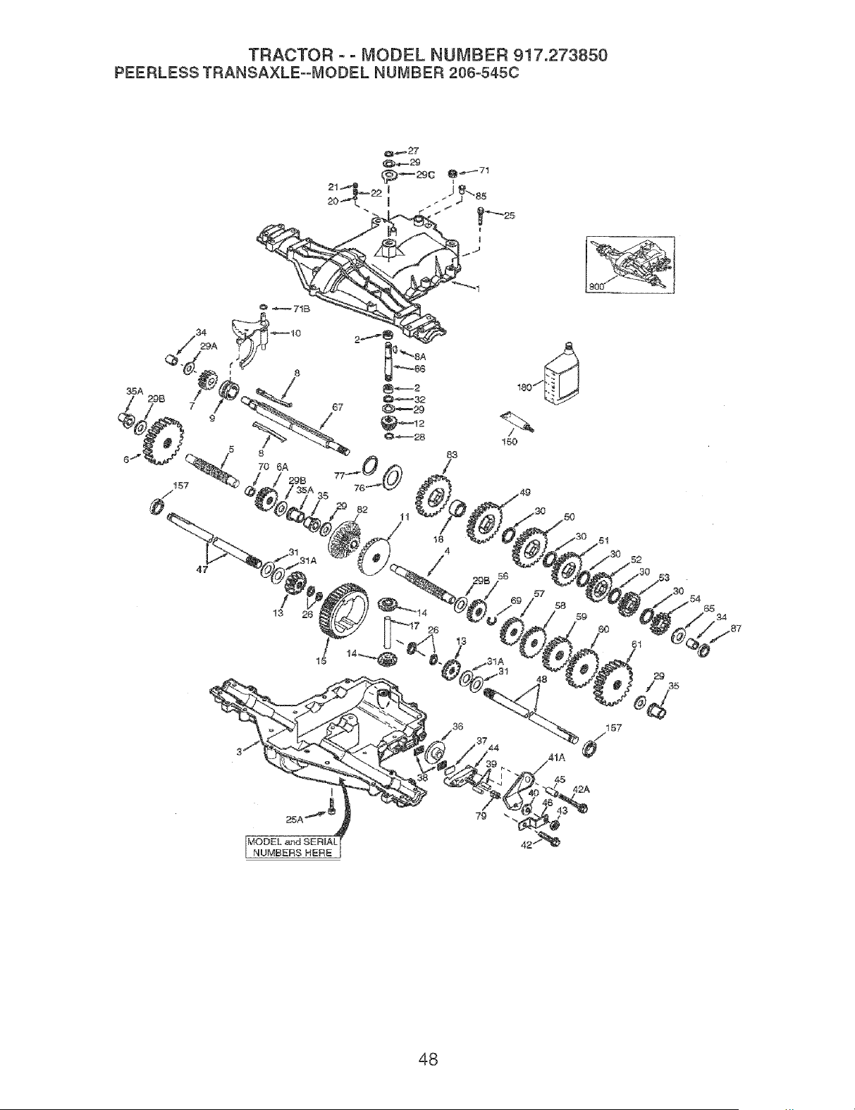
TRACTOR ° ° MODEL NUMBER 917.273850
PEERLESSTRANSAXLE--MODELNUMBER206o545C
35A
8:3
/
18
4
/
/
44
57
58
59
6,0
61
29
35
t57
#
42A
48

TRACTOR o o MODEL NUMBER 917.273850
PEERLESS TRANSAXLE==MODEL NUMBER 206=545C
KEY PART KEY PART
NO, NO, DESCRiPTiON NO, NO, DESCRiPTiON
1 772147 Transaxle Cover 39 786026 Dowel Pin
2 780086A NeedIe Bearing 5/8" 40 792076A Flat Washer =312 ID x =059W
3 770128 Transaxle Case 41A 790079 Brake Lever
4 776395 Countershaft 42 792073A Screw 1/4 - 20 x 1-1 /4"
5 776409 Output Shaft 42A 792085A Screw 1/4 - 20 x 2 1/4"
6 778364 Spur Gear (38 teeth) 43 792075 Locknut 5 / 16 - 24
6A 778369 Spur Gear (15 teeth) 44 790025 Brake Pad Holder
7 778330 Spur Gear (11 teeth) 45 786066 Spacer =2625 x 1.0
8 792180 Shift Key 46 786086 Brake Lever Bracket
8A 792047 Woodruff Key #9 47 774690 Axle (11-15 / 16" Long)
9 784352 Shift Collar 48 774691 Axte (16 - 1 / 2" long)
10 784378 Shift Rod & Fork 49 778356 Spur Gear (29 teeth)
11 778334 Bevel Gear (30 teeth) 50 778338 Spur Gear (27 teeth)
12 778309 Input Bevel Pinion (13 teeth) 51 778354 Spur Gear (23 teeth)
13 778368 BeveI Gear (13 teeth) 52 778352 Spur Gear (19 teeth)
(Include= 14) 53 778350 Spur Gear (16 teeth)
14 778368 Bevel Pinion (13 teeth) 54 778346 Spur Gear (15 teeth)
dnclude= 13) 56 778355 Spur Gear (11 teeth)
15 778370 Ring Gear (43 teeth) 57 778337 Spur Gear (13 teeth)
17 786188 Drive Pin 58 778353 Spur Gear (17 teeth)
18 786102 Spacer 1=130 X =695 59 778351 Spur Gear (21 teeth)
20 792077A Bali 5/16" dia 60 778349 Spur Gear (24 teeth)
21 792078 Set Screw 3/8 - 16 x 3/8" 61 778345 Spur Gear (25 teeth)
22 792079 Spring =310OD x =625 L 65 780189 Flat Washer =563 ID x =062W
25 792073A Screw 1/4 - 20 x lq/4" 66 776422 Input Shaft
25A 792177 Screw 1/4-20 x 1-3/8" 67 776396 Shifter & Brake Shaft
26 792125 Retaining Ring (pkg of 2) 69 792170 Retaining Ring
27 792035 Retaining Ring 70 786187 Spacer =890
28 788040 Retaining Ring 71 788069 Square Cut Ring
29 780072 Thrust Washer =627 ID x =031W 71B 788092 "O" Ring
29A 780160 Thrust Washer =762 ID x =031W 76 780090 Flat Washer 1=128 ID x =058W
29B 780051 Thrust Washer =762 ID x .031W 77 788078A Inverted Retaining Ring
29C 780199 Anti-Rotation Washer =632 79 792144 Spring =430OD x =5000 L
30 780108 Cup Washer 1=127 ID x =032W 82 778333 Bevel & Spur Gear (30 & 13
31 780001 Flat Washer =750 ID x =056W teeth)
(Use As Needed) 83 778338 Spur Gear (27 teeth)
31A 780195 Fiat Washer =750 ID x =062W 85 792154 Oil Fill Plug
32 788083 Oil Seal 5/8" 87 788089A Oil Seal 9 / 16"
34 780194 Bushing =563 150 788093A Liquid Gasket RTV Silicone
35 780193 Flanged Bushing 5 / 8" ID 157 788088A Oil SeaI 3/4"
35A 780197 Fianged Bushing =751 180 730229A Gear Oil 80W90
36 790075 Brake Disk 900 794712 Replacement MST
37 790007 Brake Pad Plate 206-545C Transaxle
38 799021 Brake Pad (pkg of 2)
NOTE: All component dimensions given in
U=S=inches 1 inch = 25=4 mm
49
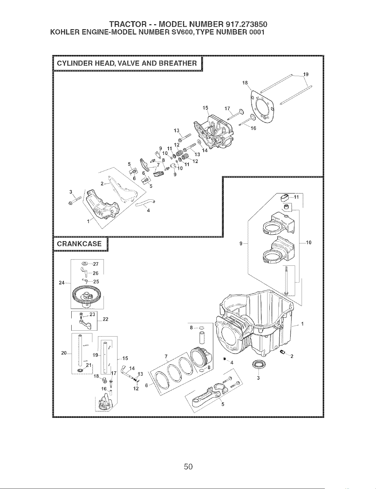
TRACTOR o o MODEL NUMBER 917.273850
KOHLER ENGmNE=MODEL NUMBER SV600,TYPE NUMBER 0001
CYUNDER HEAD, VALVE AND BREATHER I
18
13
J
1:
tt '
15 17
\
9
3
4
1/
CRANKCASE I
24........ _ 25
@j
9
5O

TRACTOR o o MODEL NUMBER 917.273850
KOHLER ENGmNE-MODEL NUMBER SV600,TYPE NUMBER 0001
HEAD/VALVE/BREATHER
CRANKCASE
KEY PART KEY PART
NO. NO. DESCRmPTmON NO. NO. DESCRmPTmON
1 20 096 03-S Kit, vaive cover (inciudes 2) 1
2 20 041 04-S Gasket, vaHve cover
3 M-645020-S Screw, hex. fiange M6xl.0x20 2 25 139 57-S
(7) 3 20 032 01-S
4 20 326 01-S Hose, breather 4 20 194 02-S
5 20 599 01-S Kit, rocker arm pivot (2) (in o 5 20 067 04-S
dudes 6) 6 20 874 01-S
6 20 086 04-S Screw, set (2)
7 20 186 01-S Arm, rocker (2) 7 20 108 01-S
8 20 086 03-S Screw, set - rocker pivot (2) 8 20 018 04-S
9 20 146 03-S Piate, push rod guide (2) 9 20 755 04-S
10 20 062 01-S Kit, retainer (2) (inciudes 6)
11 20 173 01-S Cap, vaive spring (2) 10 20 086 16-S
12 20 089 03-S Spring, vaive (2) 11 20 423 02-S
13 2008602-S Screw, hex. fiange 12 12 154 05-S
MlOx1.5x37 (6) 13
14 12 468 05-S VVasher, fiat 1/2" 14 20 144 02-S
15 20 318 01-S Head, cylinder 15 20 393 01-S
16 20 016 01-S Vaive, exhaust
17 2001701-S Vaive, intake 16 20 112 02-S
18 20 041 03-S Kit, cylinder head gasket 17 20 086 13-S
repair 18 20 032 05-S
19 20 411 02-S Rod, push (2) 19 20 144 04-S
20 20 144 05-S
21 20 468 01-S
22 20 090 01-S
23 20 086 06-S
24 20 010 03-S
25 20 089 06-S
26 20 044 16-S
27 20 468 03-S
Crankcase (USE: Short Biock
20 522 01)
Piug, sq. hd. pipe 3/8"
Seai, oii
BaH, check vaive
Rod, connecting
Piston w/Ring Set (inciudes
7,8)
Ring Set (94 mm)
Retainer, piston pin (2)
Kit, balance weight (inciudes
10,11)
Kit, screw/guide pin
Shoe, guide
CHip, hitch pin
Washer, TBD
Shaft, governor cross
Pump assembiy, oi[ ([nciudes
16-19)
Spacer, oi[ pump screw (2)
Screw, oi[ pump (2)
Sea[, oi[ pump outiet
Shaft center, cam - intake
Shaft center, cam - Exhaust
([nciudes 21 )
Washer, thrust
Lever assembiy, cam (2)
([nciudes 23)
Screw, shouider
Gear assembiy, cam ([nciudes
25°27)
Spring, ACR
Weight, ACR
Washer, thrust ° ACR (2)
NOTE: All component dimensions given in U.S.
inches 1 inch = 25.4 mm
51
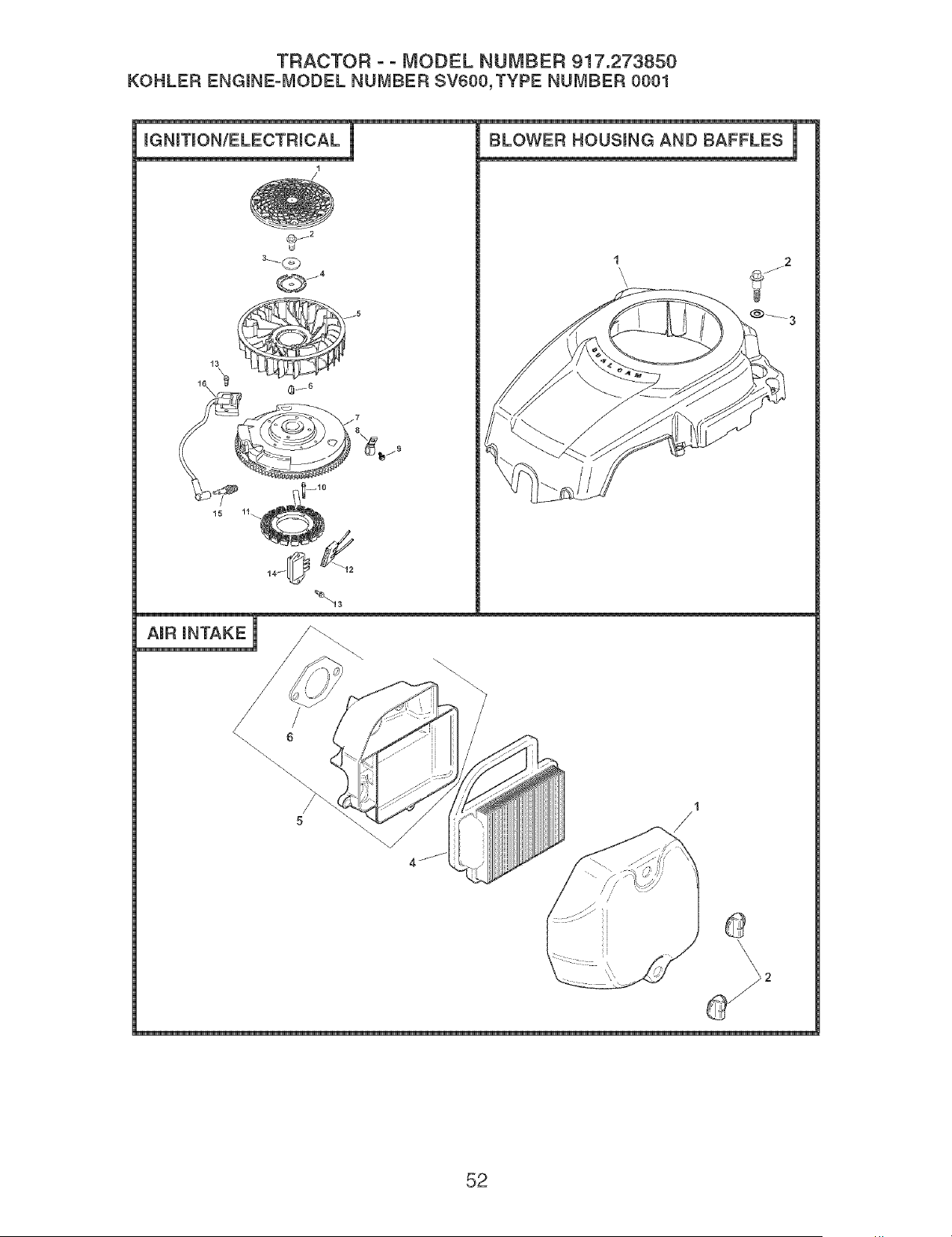
TRACTOR ° ° MODEL NUMBER 917.273850
KOHLER ENGmNE-MODELNUMBERSV600,TYPENUMBER0001
mGNmTmONIELECTRmCAL i
1
2
Q j4
/
!5 !1_
BLOWER HOUSmNG AND BAFFLES I
1
\
\,
_! 3
AmR mNTAKE
1
/
52

TRACTOR ooMODEL NUMBER 917.273850
KOHLER ENGmNE-MODELNUMBERSV600,TYPENUMBER0001
mGNmTmoN/ELECTRmCAL
KEY PART
NO. NO. DEBCRmPTmON
1 20 162 02-S Screen, grass
2 12 086 14-S Screw, hex, fHange
MlOx1,5x46
3 12 468 03-S Washer, spring 3/16"
4 20 146 02-S PHate, fan mounting
5 20 157 01-S Fan
6 X°42 o15°S Key, woodruff
7 20 025 05-S FHywheeH
8 M-561025-S Screw, hex, flange M5xO,8x25
(2)
9 231285-S CHip,came (2)
10 M°548025°S Screw, hex, hd, M5xO,8x25 (2)
11 237878°S Kit, stator
12 236602°S Connector, body
13 M°545020°S Screw, hex, fHange M5xO,8x20
(2)
14 41 403 09°S Rectifier°reguHator
15 12 132 02°S PHug, spark
16 20 584 0 I°S ModuHe, ignition
NOT ILLUSTRATED
.... 20 176 01°S Harness, wiring
BLOWER HOUSING & BAFFLES
KEY PART
NO. NO. DESCRIPTION
20 027 02°S Housing, Mower
20 086 06°S Screw, shouHder M5xO,8x36
(4)
X°25°28°S Washer, pHain
AIR INTAKE/FILTRATION
KEY PART
NO. NO. DESCRIPTION
1
2
4
5
20 096 05°S Cover, air cHeaner
25 341 03°S Knob, cover (2)
20 083 02°S EHement, air cHeaner
20 094 01°S Kit, air cHeaner base (Includes
6)
12 041 02°S Gasket, air cleaner base
NOTE: All component dimensions given in U.S.
inches 1 inch = 25.4 mm
53
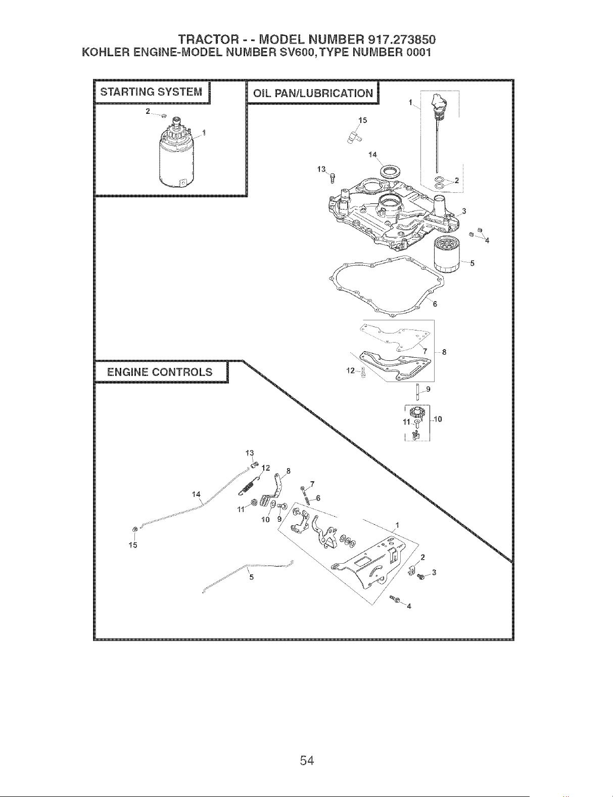
TRACTOR o o MODEL NUMBER 917.273850
KOHLER ENGmNE=mvmoDELNUMBER SV000,TYPE NUMBER 0001
2
|
OraL PAN/LUBRICATION_I _ t i
//
t4
t5
\
\
54

TRACTOR ° ° MODEL NUMBER 917.273850
KOHLER ENGmNE-mvmoDELNUMBER SV600,TYPE NUMBER 0001
STARTmNG SYSTEM
KEY PART
NO, NO, DESCRmPTmON
20 098 01°S Starter assembHy, inertia drive
25 100 31°S Nut, hex. serrated fHange (2)
OIL PAN/LU BRICATION
KEY PART
NO. NO. DESCRIPTION
1
2
3
20 040 02-S
20 153 01-S
20 009 03-S
Kit, dipstick assembHy(Hno
dudes 2)
O-Ring, dipstick (2)
Plate assembly, closure
4 25 139 60-S PHug, pipe (2)
5 52 050 02-S FHter, oH
6 20 041 01-S Gasket, cHosure pilate
7 20 096 02-S Kit, oH passage cover (Hno
dudes 8)
8 20 041 02-S Gasket, oil passage
9 20 144 03-S Shaft, governor gear
10 20 310 03°S Kit, gear and weight assembly
(Includes 11)
11 12 380 01°S Pin, governor reguHating
12 M°545013°S Screw, hex. fHange M5xO.8x13
13 M°851030°S Screw, hex. fHange
M8x1.25x30 (14)
14 2003201°S SeaH, Dill
15 25 155 02°S Connector, 90 °
ENGINE CONTROLS
KEY PART
NO. NO. DESCRIPTION
1
2
3
5
6
7
8
9
10
11
12
13
14
15
20 536 03°S
12 237 01°S
24 086 43°S
M°664020°S
20 079 02°S
12 089 11-S
20 086 10°S
20 090 02°S
52 211 04°S
X°22° 11 °S
12 1O0 07°S
20 089 07°S
25 158 11°S
20 079 01°S
25 158 08°S
Control assembHy, speed
Clamp, cabHe
Screw, torx hd. ctsk.
M5xO.8x16
Screw, lobed sckt. M6xl .Ox20
(2)
Linkage, choke - singHe wire
Spring, speed control (2)
Screw, thread forming
M4xO.7x25 (2)
Lever, governor
BoHt, round head 1/4°20xl"
Washer, Hock 1/4"
Nut, hex. fHange 1/4°20"
Spring, governor
Bushing, throttHe Hinkage
Linkage, throttHe
Bushing, Hinkage retaining
NOTE: All component dimensions given in U.S.
inches 1 inch = 25.4 mm
55
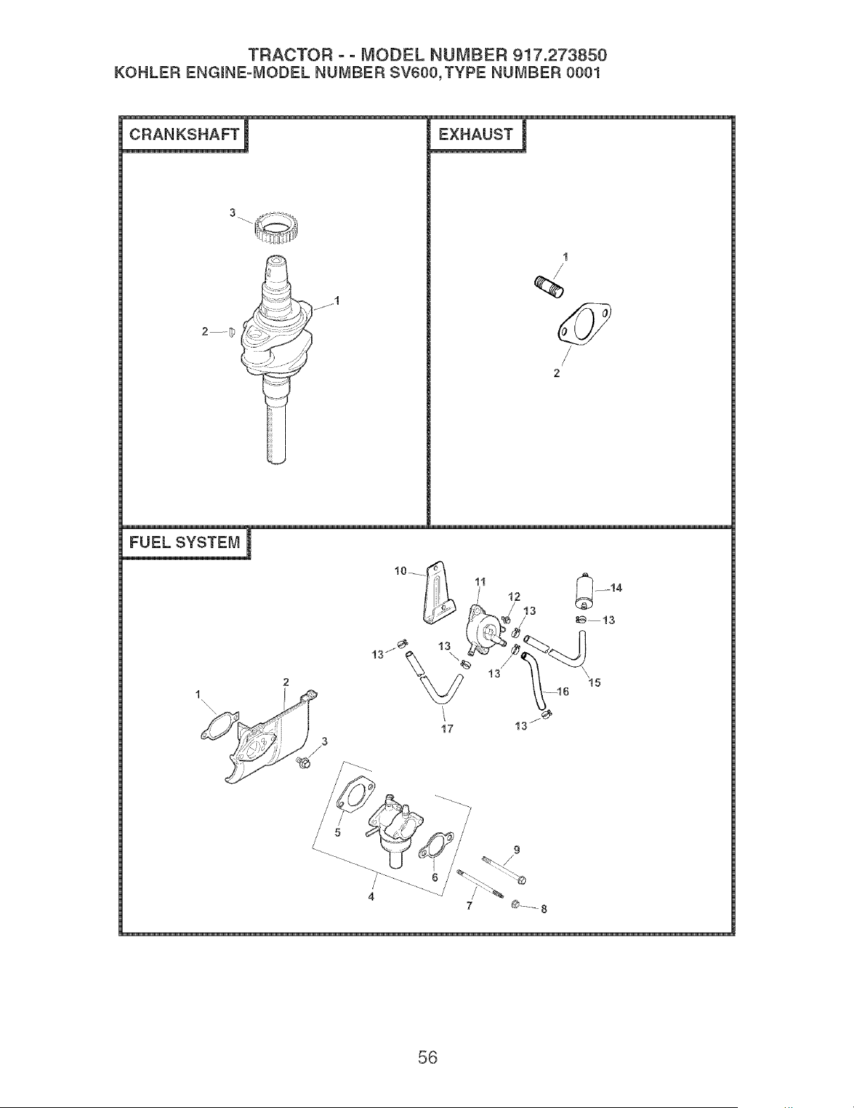
TRACTOR o o MODEL NUMBER 917.273850
KOHLER ENGmNE=iVIODEL NUMBER SV600,TYPE NUMBER 0001
CRANKSHAFT !
2--D
EXHAUST !
/
13
'15
17
13
4
9
/
56

TRACTOR o o MODEL NUMBER 917.273850
KOHLER ENGmNE-mvmODELNUMBER SV600,TYPE NUMBER 0001
CRANKSHAFT
KEY PART
NO. NO. DESCRmPTmON
1 20 014 14°S Crankshaft (inciudes 2)
2 X°42° 15°S Key 3/16"
3 20 043 12°S Gear, crankshaft
EXHAUST
KEY PART
NO. NO. DESCRIPTION
25 072 04-S
20 041 12°S
Stud, exhaust (2)
Gasket, exhaust
20 522 01 Short Block
20 755 05°S Gasket Set
FUEL SYSTEM
KEY PART
NO. NO. DESCRIPTION
1
2
3
5
6
7
10
20 041 07°S
20 265 01°S
M°651020°S
20 853 01°S
12 041 01°S
12 041 02°S
20 072 03°S
M°641060°S
20 086 11 °S
20 126 02°S
Gasket, heat deflector
Deflector, heat
Screw, hex. fiange
M6x1.0x20
Carburetor w/gaskets
(Includes 5,6)
Gasket, carburetor
Gasket, air cleaner
Stud, carburetor
Nut, hex. flange M6x1.0
Screw, carb
S60x 1.42x85
Bracket, fuel pump
11 24 393 16-S
12 M°545010°S Screw, hex. flange
M5x0.8xl0 (2)
13 25 237 14°S Clamp, hose (6)
14 25 050 08°S FHter, fuei
15 41 353 15°S Line, fuel 2" (pump to
fiiter)
16 24 353 12°S Line, fuei 11"(puise to
pump)
17 20 353 01 °S Line, fuel 15°3/4" (pump
to carb)
NOTILLUSTRATED
°°
°°
°°
°°
X°22°11°S Washer, Hock 1/4"
(ground)
66 431 04°S Sieeve, insulating (for
11" fuei Hne)
12 757 02°S Kit, fioat
12 757 03°S Kit, carburetor repair
12 757 33°S Kit, solenoid repair
12 757 37°S Kit, bowi repiacement
w/gaskets
12 454 03°S Tie, wire
NOTE: All component dimensions given in U.S.
inches 1 inch = 25.4 mm
57

58

SUGGESTED GUIDE FOR SIGHTING SLOPES FOR SAFE OPERATION
L_
c.O
ONLY RIDE UP AND DOWN HILL,
NOT ACROSS HILL
15 DEGREES MAX.
WARNING: To avoid serious injury, operate your tractor up and
down the face of slopes, never across the face. Do not mow
slopes greater than 15 degrees. Make turns gradually to prevent
tipping or loss of control. Exercise extreme caution when
changing direction on slopes.
1. Fo_d this page atong dotted Nine indicated above.
2. HoNd page before you so that its left edge is vertically parallel to a tree
trunk or other upright structure.
3o Sight across the fold in the direction of hiIN sJope you want to measure.
4, Compare the angle of the fo_d with the s_ope of the hilL

iiiiiiiiiiiiiiiiiii
iiiiiiiiiiiiiiiiiii_
iiiiiiiiiiiiiiiiiii
iiiiiiiiiiiiiiiiiii
iiiiiiiiiiiiiiiiiii
iiiiiiiiiiiiiiiiiii
iiiiiiiiiiiiiiiiiii
iiiiiiiiiiiiiiiiiii
iiiiiiiiiiiiiiiiiii
iiiiiiiiiiiiiiiiiii
iiiiiiiiiiiiiiiiiii
iiiiiiiiiiiiiiiiiii
iiiiiiiiiiiiiiiiiii
iiiiiiiiiiiiiiiiiii
iiiiiiiiiiiiiiiiiii
iiiiiiiiiiiiiiiiiii
iiiiiiiiiiiiiiiiiii
iiiiiiiiiiiiiiiiiii
iiiiiiiiiiiiiiiiiii
iiiiiiiiiiiiiiiiiii
iiiiiiiiiiiiiiiiiii
iiiiiiiiiiiiiiiiiii
iiiiiiiiiiiiiiiiiii
iiiiiiiiiiiiiiiiiii
iiiiiiiiiiiiiiiiiii
iiiiiiiiiiiiiiiiiii
iiiiiiiiiiiiiiiiiii
iiiiiiiiiiiiiiiiiii
iiiiiiiiiiiiiiiiiii
iiiiiiiiiiiiiiiiiii
iiiiiiiiiiiiiiiiiii
iiiiiiiiiiiiiiiiiii
iiiiiiiiiiiiiiiiiii
iiiiiiiiiiiiiiiiiii
iiiiiiiiiiiiiiiiiii
iiiiiiiiiiiiiiiiiii
iiiiiiiiiiiiiiiiiii
iiiiiiiiiiiiiiiiiii
iiiiiiiiiiiiiiiiiii
iiiiiiiiiiiiiiiiiii
iiiiiiiiiiiiiiiiiii
iiiiiiiiiiiiiiiiiii
iiiiiiiiiiiiiiiiiii
iiiiiiiiiiiiiiiiiii
iiiiiiiiiiiiiiiF
iiiiiiiiiiiiiiii
iiiiiiiiiiiiiiii
iiiiiiiiiiiiiiii
iiiiiiiiiiiiiiii
iiiiiiiiiiiiiiii
iiiiiiiiiiiiiiii
iiiiiiiiiiiiiiii
iiiiiiiiiiiiiiii
iiiiiiiiiiiiiiii
iiiiiiiiiiiiiiii
iiiiiiiiiiiiiiii
iiiiiiiiiiiiiiii
iiiiiiiiiiiiiiii
iiiiiiiiiiiiiiii
iiiiiiiiiiiiiiii
iiiiiiiiiiiiiiii
iiiiiiiiiiiiiiii
iiiiiiiiiiiiiiii
iiiiiiiiiiiiiiii
iiiiiiiiiiiiiiii
iiiiiiiiiiiiiiii
iiiiiiiiiiiiiiii
iiiiiiiiiiiiiiii
iiiiiiiiiiiiiiii
iiiiiiiiiiiiiiii
iiiiiiiiiiiiiiii
iiiiiiiiiiiiiiii
iiiiiiiiiiiiiiii
iiiiiiiiiiiiiiii
iiiiiiiiiiiiiiii
iiiiiiiiiiiiiiii
Your Home
For repair - in your home - of all major brand appliances,
lawn and garden equipment, or heating and cooling systems,
no matter who made it, no matter who sold it!
For the replacement parts, accessories and
owner's manuals that you need to do-it-yourself.
For Sears professional installation of home appliances
and items like garage door openers and water heaters.
1-800-4-MY-HOME ® Anytime, day or night
(1-800-469-4663) (U.S.A. and Canada)
www.sears.com www.sears.ca
Our Home
For repair of carry-in products like vacuums, lawn equipment,
and electronics, call or go on-line for the nearest
Sears Parts and Repair Center.
1-800-488-1222 Anytime, day or night (U.S.A. only)
www.sears.corn
To purchase a protection agreement (U.S.A.)
or maintenance agreement (Canada) on a product serviced by Sears:
1-800-827-6655 (U.S.A.) 1-800-361-6665 (Canada)
Para pedir servicio de reparaci6n
a domicilio, y para ordenar piezas:
1-888-SU-HOGAR sM
(1-888-784-6427)
Au Canada pour service en frangais:
1-800-LE-FOYER Mc
(1-800-533-6937)
::iiiiiiiiiiiiiiiii:
::iiiiiiiiiiiiiiiii:
::iiiiiiiiiiiiiiiii:
::iiiiiiiiiiiiiiiii:
::iiiiiiiiiiiiiiiii:
::iiiiiiiiiiiiiiiii:
::iiiiiiiiiiiiiiiii:
::iiiiiiiiiiiiiiiii:
::iiiiiiiiiiiiiiiii:
::iiiiiiiiiiiiiiiii:
::iiiiiiiiiiiiiiiii:
::iiiiiiiiiiiiiiiii:
::iiiiiiiiiiiiiiiii:
::iiiiiiiiiiiiiiiii:
::iiiiiiiiiiiiiiiii:
::iiiiiiiiiiiiiiiii:
::iiiiiiiiiiiiiiiii:
::iiiiiiiiiiiiiiiii:
::iiiiiiiiiiiiiiiii:
::iiiiiiiiiiiiiiiii:
::iiiiiiiiiiiiiiiii:
::iiiiiiiiiiiiiiiii:
::iiiiiiiiiiiiiiiii:
i_i_i_iiii_ii!ii!ii!ii!ii!ii!ii!ii!ii!ii!ii!ii!ii!ii!iill
_,_EAR_ o241o
© Sears, Roebuckand Co.
® Registered Trademark / TMTrademark / SMService Mark of Sears, Roebuck and Co.
® Marca Registrada / TMMarca de Fabrica / SMMarca de Servicio de Sears, Roebuck and Co.
MCMarque de commerce / MDMarque d_pos6e de Sears, Roebuck and Co.
189047 Re',/. 6 8.2.04 TRiMH Printed in U.S.A.


