
490 / 590e
TM
Manuals in additional languages:
http://www.schwinntness.com
ASSEMBLY MANUAL / OWNER’S MANUAL
490 / 590e
TM

2
TABLE OF CONTENTS
Important Safety Instructions 3
Safety Warning Labels / Serial Number 6
Specications 9
Before Assembly 9
Parts 10
Hardware 11
Tools 11
Assembly 12
Using JRNY™ with Your Machine 29
Bluetooth
®
Heart Rate Monitor 29
Moving the Machine 30
Leveling the Machine 30
Features 31
Console Features 32
Using JRNY™ with Your Machine 34
Bluetooth
®
Heart Rate Monitor 35
Operation 37
Mounting and Dismounting Your Machine 37
Getting Started 37
Power Up / Idle Mode 38
Manual (Quick Start) Program 38
Prole Programs 39
Modify Display of Workout Values 40
Pausing or Stopping 41
Workout Summary Mode 41
Console Setup Mode 42
Maintenance 44
Maintenance Parts 45
Troubleshooting 47
To validate warranty support, keep the original proof of purchase and record the following information:
Serial Number __________________________
Date of Purchase ____________________
If purchased in US/Canada: To register your product warranty, go to: www.SchwinnFitness.com/register
Or call 1 (800) 605–3369.
If purchased outside US/Canada: To register your product warranty, contact your local distributor.
For details regarding product warranty or if you have questions or problems with your product, please contact your
local distributor. To nd your local distributor, go to: global.schwinntness.com
Nautilus, Inc., 5415 Centerpoint Parkway, Groveport, OH 43125 USA, www.NautilusInc.com - Customer Service: North America
(800) 605-3369, [email protected] | Nautilus (Shanghai) Fitness Equipments Co, Ltd, Room 1701 &1702, 1018 Changning Road,
Changning District, Shanghai, China 200042, www.nautilus.cn - 86 21 6115 9668 | outside U.S. www.nautilusinternational.com | © 2023
Nautilus, Inc. | Schwinn, the Schwinn Quality logo, Schwinn 590e, JRNY and Nautilus are trademarks owned by or licensed to Nautilus,
Inc., which are registered or otherwise protected by common law in the United States and other countries. Other trademarks are the
property of their respective owners. The Bluetooth
®
word mark and logos are registered trademarks owned by Bluetooth SIG, Inc., and
any use of such marks by Nautilus, Inc. is under license.
ORIGINAL MANUAL - ENGLISH VERSION ONLY

3
When using an electrical appliance, basic precautions should always be followed, including the following:
This icon means a potentially hazardous situation which, if not avoided, could result in death or serious
injury.
Obey the following warnings:
Read and understand all Warnings on this machine.
Carefully read and understand the Assembly/Owner’s Manual.
Carefully read and understand the Assembly instructions. Read and understand the
complete Manual. Keep the Manual for future reference.
To reduce the risk of electrical shock or unsupervised usage of the equipment, always
unplug this machine from the electrical outlet immediately after using and before
cleaning.
WARNING
!
WARNING indicates a hazardous
situation which, if not avoided, could
result in death or serious injury.
DANGER
!
DANGER indicates a hazardous
situation which, if not avoided, will
result in death or serious injury.
CAUTION
!
CAUTION indicates a hazardous
situation which, if not avoided, could
result in minor or moderate injury.
NOTICE
NOTICE is used to address practices
not related to personal injury.
!
To decrease the risk of burns, electric shock, or injury to persons, read and
understand the complete Assembly/Owner’s Manual. Failure to follow these guidelines
can cause a serious or possibly fatal electrical shock or other serious injury.
• Keep bystanders and children away from the product you are assembling at all times.
• Do not connect power supply to the machine until instructed to do so.
• The machine should never be left unattended when plugged in. Unplug from outlet when not in use, and before putting
on or taking off parts.
• Before each use, examine the machine for damage to power cord, loose parts or signs of wear. Do not use if found in
this condition. If purchased in US/Canada, contact Customer Service for repair information. If purchased outside US/
Canada, contact your local distributor for repair information.
• Do not drop or put objects into any opening of the machine.
• Do not assemble this machine outdoors or in a wet or moist location.
• Make sure assembly is done in an appropriate work space away from foot traffic and exposure to bystanders.
• Some components of the machine can be heavy or awkward. Use a second person when doing the assembly steps
involving these parts. Do not do steps that involve heavy lifting or awkward movements on your own.
• Set up this machine on a solid, level, horizontal surface.
• Do not try to change the design or functionality of this machine. This could compromise the safety of this machine and
will void the warranty.
• If replacement parts are necessary, use only genuine Nautilus replacement parts and hardware. Failure to use genuine
replacement parts can cause a risk to users, keep the machine from operating correctly and void the warranty.
• Do not use until the machine has been fully assembled and inspected for correct performance in accordance with the
Manual.
• Use this machine only for its intended use as described in this manual. Do not use attachments not recommended by
the manufacturer.
• Do all assembly steps in the sequence given. Incorrect assembly can lead to injury or incorrect function.
• Connect this machine to a properly grounded/earthed outlet only (see Grounding or Earthing Instructions).
• Keep the power cord away from heat sources and hot surfaces.
• Do no operate where aerosol products are being used.
• To disconnect, turn all controls to the off position, then remove plug from outlet.
• Silicone lubricant is not intended for human consumption. Keep out of reach of children. Store in a safe place.
•
SAVE THESE INSTRUCTIONS.
IMPORTANT SAFETY INSTRUCTIONS

4
Before using this equipment, obey the following warnings:
Read and understand the complete Manual. Keep the Manual for future reference.
Read and understand all warnings on this machine. If at any time the Warning labels become loose,
unreadable or dislodged, replace the labels. If purchased in US/Canada, contact Customer Service for
replacement labels. If purchased outside US/Canada, contact your local distributor for them.
To reduce the risk of electrical shock or unsupervised usage of the equipment, always
unplug the power cord from the wall outlet and/or the machine and wait 5 minutes
before cleaning, maintaining or repairing the machine. Place the power cord in a
secure location.
• Children must not be let on or near to this machine. Moving parts and other features of the machine can be dangerous
to children.
• Not intended for use by anyone under 14 years of age. Individuals between 14 and 17 years of age must be supervised
when using this machine.
• Consult a physician before you start an exercise program. Stop exercising if you feel pain or tightness in your chest,
become short of breath, or feel faint. Contact your doctor before you use the machine again. Use the values calculated
or measured by the machine’s computer for reference purposes only.
• Individual human power which is required to utilize this machine for exercise may be different than the mechanical
power displayed.
• Before each use, examine this machine for loose parts or signs of wear. Do not use if found in this condition. Monitor
the Handlebars, Pedals, and Crank Arms closely. If purchased in US/Canada, contact Customer Service for repair
information. If purchased outside US/Canada, contact your local distributor for repair information.
• Connect this machine to a correctly grounded outlet; consult a licensed electrician for assistance.
• Do not let liquids touch the electronic controller. If it does, the controller must be inspected and tested for safety by an
approved technician before it can be used again.
• The electrical wiring for the residence in which the machine will be used must obey the applicable local and provincial
requirements.
• Maximum user weight limit: 150 kg (330 lb). Do not use if you are over this weight.
• This machine is intended for Home/Consumer or Studio/Institutional use. When the machine is placed into a Studio/
Institutional environment, usage should be limited to less than 3 hours per day, and it should only be used in areas
where access and control of the machine are managed and supervised by approved staff. The degree of management
depends among other things on the specific setting in which the machine is placed, security of that environment, and
familiarity of the users with the equipment. Because others will have used the machine previously, make sure the
incline, pedals and handlebars are correctly adjusted, tightened and secured.
• Do not wear loose clothing or jewelry. This machine contains moving parts. Do not put fingers, feet, or other objects into
moving parts of the exercise equipment.
• Always wear rubber soled athletic shoes when you use this machine. Do not use the machine with bare feet or only
wearing socks.
• Set up and operate this machine on a solid, level, horizontal surface.
• Make the Foot Pedals stable before you step on them. Use caution when you step on and off the machine.
• Do not operate this machine outdoors or in moist or wet locations.
• Keep at least 0.6 m (24 in) along the side used to access the machine and to the rear of the machine clear. This is the
recommended safe distance for access and passage around and emergency dismounts from the machine. Keep third
parties out of this space when machine is in use.
• Do not over exert yourself during exercise. Operate the machine in the manner described in this manual.
• Correctly adjust and safely engage all Positional Adjustment Devices. Make sure that the Adjustment Devices do not hit
the user.
• Keep the Foot Pedals and Handlebars clean and dry.
• Perform all regular and periodic maintenance procedures recommended in the Owner’s Manual.

5
• Exercise on this machine requires coordination and balance. Be sure to anticipate that changes in incline angle and
resistance level can occur during workouts, and be attentive in order to avoid loss of balance and possible injury.
• This machine is not equipped with a freewheel and therefore the moving parts cannot be stopped immediately.
• Since this machine operates with a fixed gear, do not back, or reverse, pedal. Doing so may loosen the Legs and
Pedals, which could result in damage to the machine and/or injury to the user. Never operate this machine with loose
Legs and Pedals.
• This machine cannot stop the Pedals or Upper Handlebars independently of the Flywheel. Reduce the pace to slow
the Flywheel, Upper Handlebars and Pedals to a stop. Do not dismount the machine until the Pedals and Upper
Handlebars have come to a complete stop.
• Do not drop or put objects into any opening of the machine.
• Keep power cord away from heat source and hot surfaces.
• This machine must be connected to an appropriate, dedicated electrical circuit. Nothing else must be connected to the
circuit.
• Connect this machine to a correctly grounded/earthed outlet; consult a licensed electrician for assistance.
• Do not operate where aerosol products are being used.
• A machine should never be left unattended when plugged in. Unplug from outlet when not in use, and before putting on
or taking off parts.
• Use this machine only for its intended use as described in this manual. Do not use attachments not recommended by
the manufacturer.
• This appliance is not intended for use by persons with reduced physical, sensory or mental capabilities, or lack of
knowledge, unless they have been given supervision or instruction concerning use of the appliance by a person
responsible for their safety. Keep children under the age of 14 away from this machine.
• Children should be supervised to ensure that they do not play with the appliance.
•
SAVE THESE INSTRUCTIONS.
6
SAFETY WARNING LABELS AND SERIAL NUMBER
Product Specication and Serial Number
7
Safety Warning Labels and Serial Number
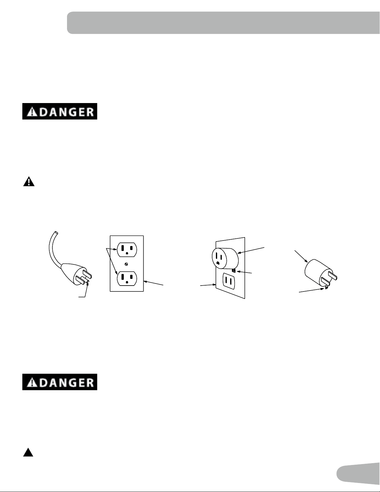
Metal Screw
Tab for
Grounding
Screw
Adapter
Grounded
Outlet Box
Grounded
Outlet
Grounding Pin
Grounding Instructions
This product must be grounded. If it should malfunction or break down, grounding provides a path of least resistance for
electric current to reduce the risk of electric shock. This product is equipped with a cord having an equipment-grounding
conductor and a grounding plug. The plug must be plugged into an appropriate outlet that is properly installed and
grounded in accordance with all local codes and ordinances.
Improper connection of the equipment-grounding conductor can result in a risk of
electric shock. Check with a qualied electrician or serviceman if you are in doubt as
to whether the product is properly grounded. Do not modify the plug provided with the
product – if it will not t the outlet, have a proper outlet installed by a qualied
electrician.
If you connect the machine to an outlet with GFI (ground fault interrupt) or AFI (arc fault interrupt), machine operation can
cause the circuit to trip.
This machine is for use on a nominal 120-V circuit, and has a grounding plug that looks like the plug
illustrated below. A temporary adapter that looks like the adapter illustrated may be used to connect this
plug to a 2-pole receptacle as shown if a properly grounded outlet is not available.
The temporary adapter should be used only until a properly grounded outlet can be installed by a qualied electrician.
The tab for the grounding screw must be connected to a permanent ground such as a properly grounded outlet box cover.
Whenever the adapter is used, it must be held in place by a metal screw.
Earthing Instructions (for a 220-240V AC system)
This product must be electrically earthed. If a malfunction occurs, correct earthing decreases the risk of electric shock.
The power cord is equipped with an equipment-earthing conductor, and must be connected to an outlet that is properly
installed and earthed.
The electrical wiring must comply with all applicable local and provincial standards
and requirements. Incorrect connection of the equipment-earthing conductor can
result in a risk of electric shock. Consult a licensed electrician if you are not sure that
the machine is correctly earthed. Do not change the plug on the machine – if it does
not t the outlet, have a correct outlet installed by a licensed electrician.
If you connect the machine to an outlet with RCBO (Residual-Current circuit Breaker with Overload protection), machine
operation can cause the circuit to trip. A Surge Protector Device is recommended to protect the machine.
!
If a Surge Protector Device (SPD) is used with this machine, be sure that it matches the power rating of this
equipment (220-240V AC). Do not connect other appliances or devices to the surge protector in combination
with this machine.

8
FCC Compliance
!
Changes or modications to this unit not expressly approved by the party responsible for compliance could
void the user’s authority to operate the equipment.
The machine and power supply comply with Part 15 of the FCC rules. Operation is subject to the following two conditions:
(1) This device may not cause harmful interference, and (2) this device must accept any interference received, including
interference that may cause undesired operation.
Note: This machine and power supply have been tested and found to comply with the limits for a Class B digital
device, pursuant to Part 15 of the FCC Rules. These limits are designed to provide reasonable protection against
harmful interference in a residential installation. This equipment generates, uses and can radiate radio frequency
energy and, if not installed and used in accordance with the instructions, may cause harmful interference to radio
communications.
However, there is no guarantee that interference will not occur in a particular installation. If this equipment does cause
harmful interference to radio or television reception, which can be determined by turning the equipment o and on, the
user is encouraged to try to correct the interference by one or more of the following measures:
• Reorient or relocate the receiving antenna.
• Increase the separation between the equipment and receiver.
• Connect the equipment into an outlet on a circuit dierent from that to which the receiver is connected.
• Consult the dealer or an experienced radio/TV technician for help.
This product complies with the European Radio Equipment Directive 2014/53/EU
!
Make sure that the product is connected to an outlet having the same conguration as the plug. Use the
appropriate adapter supplied with this product.
9
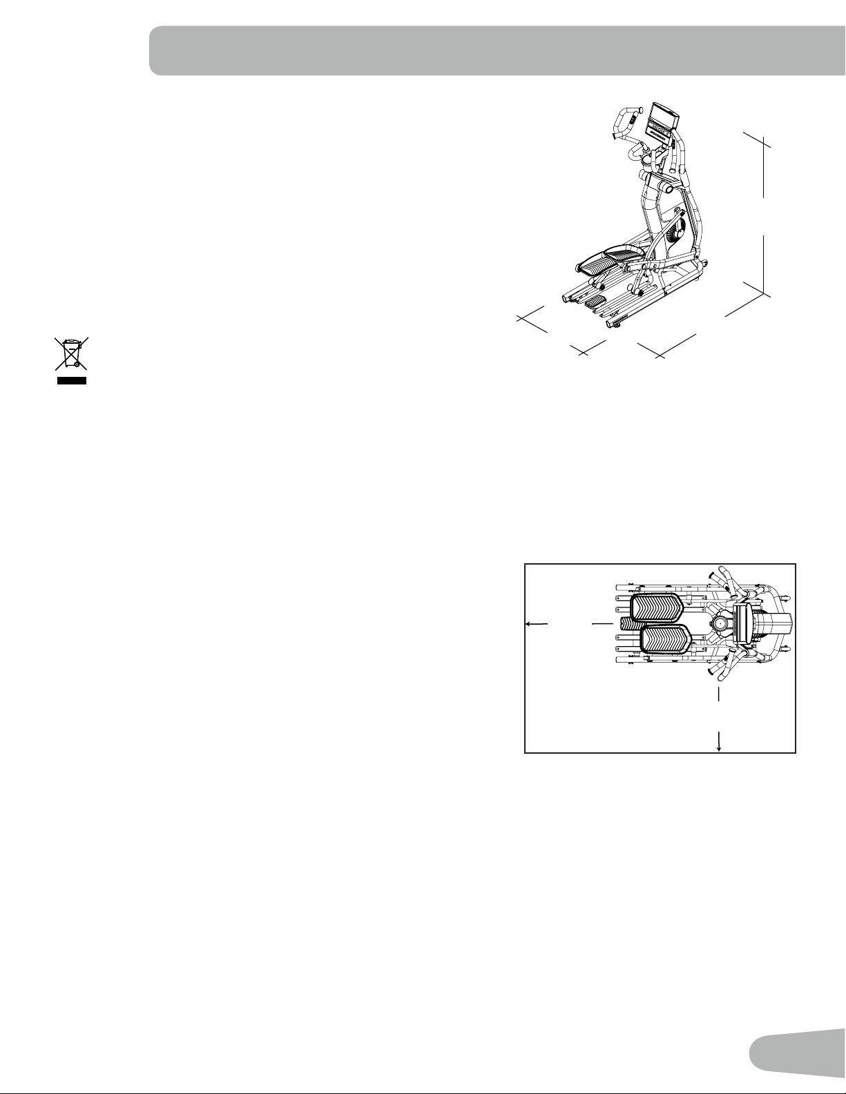
Before Assembly
Select the area where you are going to set up and operate your machine. For safe operation, the location must be on a
hard, level surface. Allow a minimum workout area of 82.1 in x 57.9 in (208.5 cm x 147.1 cm). Keep the workout area clear
0.6 m (24 in) along the side used to access the machine and to the rear of the machine. Be sure that the workout space
you are utilizing has adequate height clearance, taking into consideration the height of the user and the maximum incline
of the elliptical machine. Estimated time to assemble the machine is 60 - 90 minutes.
NOTICE: Inspect the machine for damaged parts due to delivery. If
damage is found, contact Customer Service (if inside US/
Canada) or your local distributor (if outside US/Canada) for
assistance.
Basic Assembly
Follow these basic points when you assemble your machine:
• Read and understand the “Important Safety Instructions” before
assembly.
• Collect all the pieces necessary for each assembly step.
• Using the recommended wrenches, turn the bolts and nuts to the right (clockwise) to tighten, and the left
(counterclockwise) to loosen, unless instructed otherwise.
• When attaching 2 pieces, lightly lift and look through the bolt holes to help insert the bolt through the holes.
• The assembly requires 2 people.
• Do not use any power tools for assembly.
Machine Mat
The Schwinn™ Machine Mat is an optional accessory that helps keep your workout area clear and adds a layer of
protection to your oor. The rubber machine mat provides a non-slip, rubber surface which limits static discharge and
reduces the possibility of display errors. If possible, put your Schwinn™ Machine Mat in your selected workout area before
you begin assembly.
To order the optional machine mat, contact Customer Service (if purchased in US/Canada) or your local distributor (if
purchased outside US/Canada).
Power Requirements: 120V 220V
Operational Voltage: 110-127V AC, 60Hz 220V - 240V AC, 50Hz
Operating Current: 2A 2A
Maximum User Weight: 150 kg (330 lb)
Total Surface Area (footprint) of equipment: 12,723 cm
2
Maximum Pedal Height - with full incline: 28.3 in ( 72 cm)
Machine Weight: approx. 84.8 kg (187 lb)
This product complies with the European Radio Equipment Directive
2014/53/EU
DO NOT dispose of this product as refuse. This product is to be
recycled. For proper disposal of this product, please follow the
prescribed methods at an approved waste center.
172.6 cm
( 68 in )
86.2 cm
( 33.9 in )
147.6 cm ( 58.1 in )
2.1 m (82.1 in)
1.5 m
(57.9
in)
0.6 m
( 24 in )
0.6 m
( 24 in )
SPECIFICATIONS / BEFORE ASSEMBLY
10
14
3
2
4
7
8
4
9
3
5
10
11
12
13
1
6
15
16
*
*
*
*
17
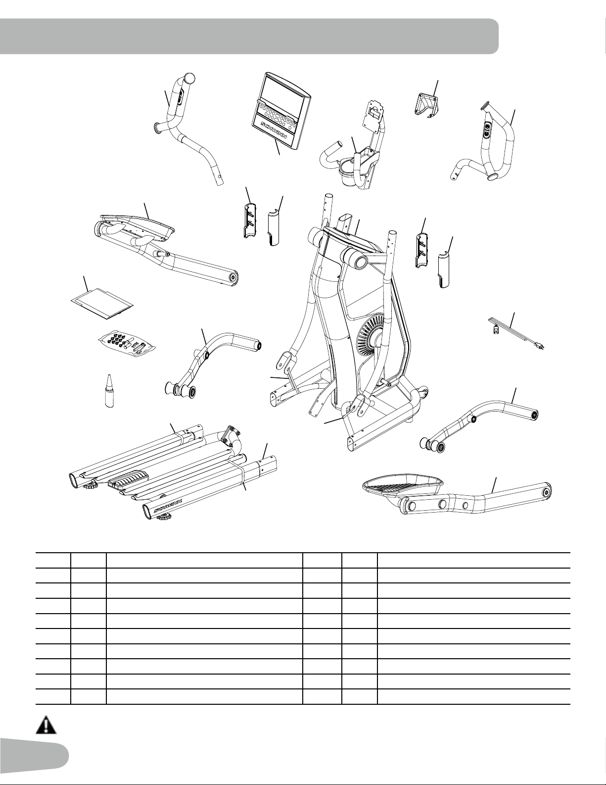
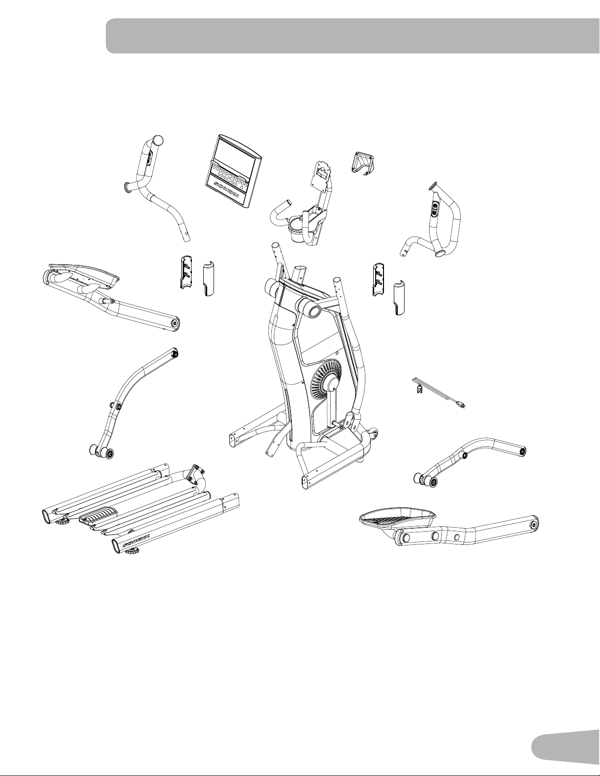
A right (“ R ”) and left (“ L ”) decal has been applied to some parts to assist with assembly.
Item Qty Description Item Qty Description
1 1 Console Assembly 10 1 Leg, Right
2 1 Upper Handlebar, Left 11 1 Pedal, Right
3 2 Handlebar Cover, Interior 12 1 Rail Assembly *
4 2 Handlebar Cover, Exterior 13 1 Leg, Left
5 1 Main Assembly * 14 1 Pedal, Left
6 1 Console Mast 15 1 Document Kit
7 1 Console Pivot Cover 16 1 Silicone Lubricant, Bottle
8 1 Upper Handlebar, Right 17 1 Hardware Bag
9 1 Power Cord
DO NOT CUT THE SHIPPING ZIP-TIES on the Rail Assembly or Main Assembly until instructed. *
PARTS
11
Item Qty Description
A 20 Button Head Flange Screw, M8x1.25x15 Black
B 2 Button Head Flange Screw with Wide Washer,
M8x1.25x20 Black
C 2 Pivot Pin
D 4 Self-Tapping Screw, M3.9x15
Note: Select pieces of Hardware may have been provided as spares. Be aware that there may be remaining
Hardware after the proper assembly of your machine.
Tools
Included Not Included
6mm
#2
13mm
15mm
19mm
A
B D
C
HARDWARE / TOOLS
Hardware
A Cloth or
Paper Towel
Clockwise
Counter-clockwise
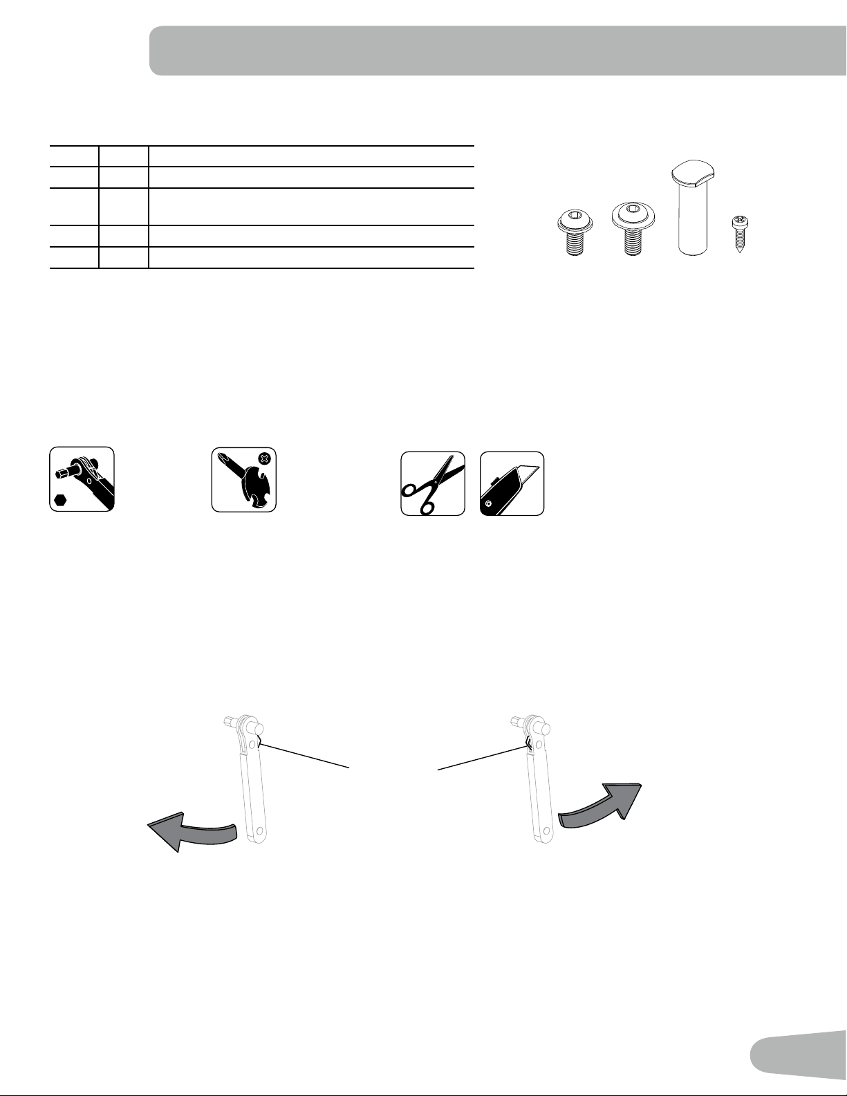
Using the Ratchet Tool
A ratchet is provided to assist with the assembly process. When properly set, the ratchet can be used to quickly remove
and attach hardware. Rotate the ratchet handle to see if the ratchet handle is set to turn in the desired direction.
Directional Switch set to tighten hardware: Directional Switch set to remove or uninstall hardware:
(Clockwise) (Counter-clockwise)
If the tool does not rotate the hardware in the desired direction use your nger or thumb to push the Directional Switch
until it snaps to the other side. The tool should now allow rotation of the hardware in the other direction.
1. Insert the ratchet bit into the hardware, and rotate the ratchet handle in the direction you wish to turn the fastener.
2. When there is no more room to move the ratchet handle, rotate the handle back to the starting point. The ratchet
mechanism will not turn the hardware when the handle is being rotated back to the starting point.
3. Once the ratchet handle is back in the start position, rotate the ratchet handle again in the direction you wish to turn
the hardware.
4. Repeat until the hardware is tightened or loosened as needed.
Directional Switch
12
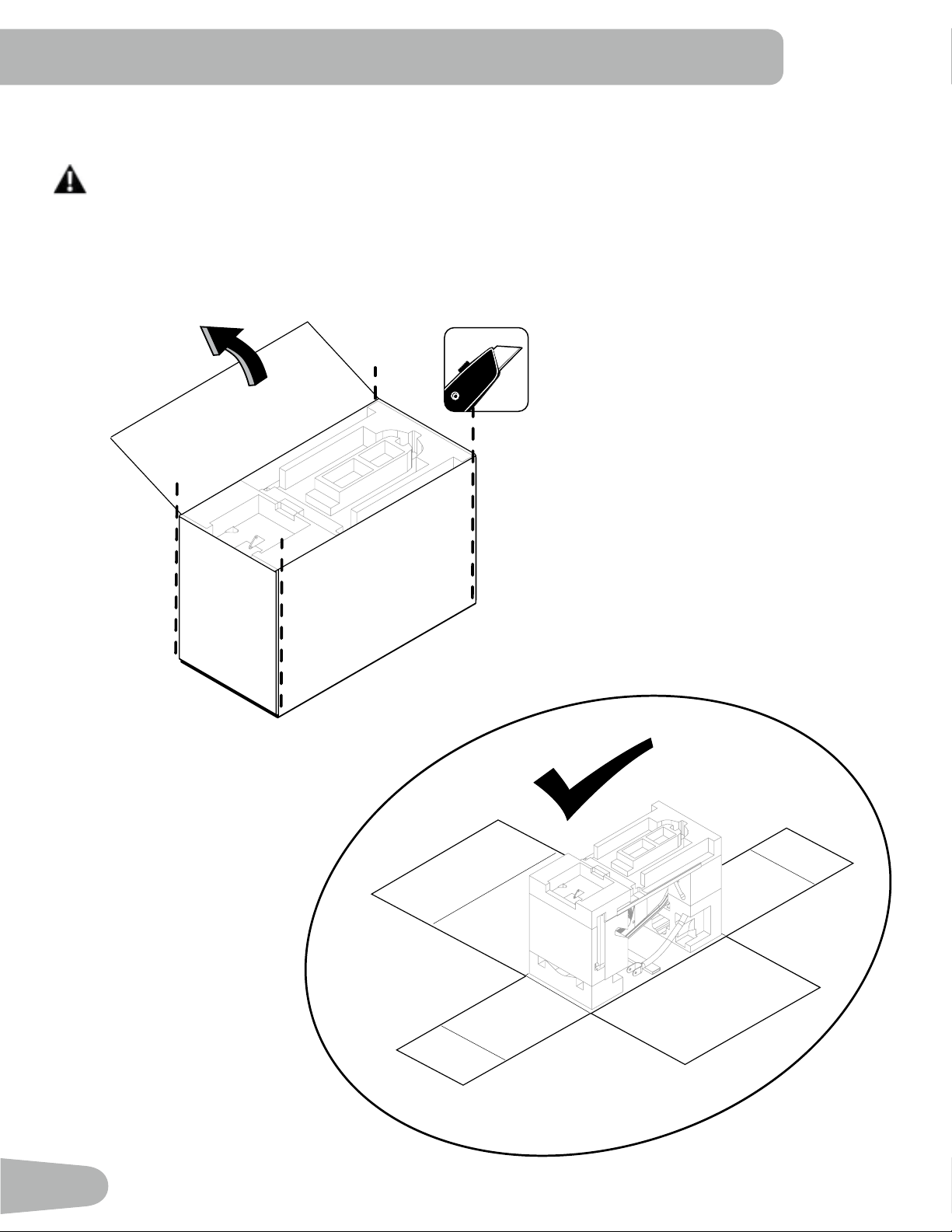
1. With the Box Near the Intended Workout Area, Open the Top Flap of the Box and Safely Cut
the Corners of the Box
Be sure not to injure yourself when cutting the box with scissors or a box cutter. Keep hands and ngers
away from the motion of the scissors or box cutter at all times. Be aware that the box has shipping staples
which can be harmful. Keep your hands and ngers away from them at all times.
Note: The box can be used to protect the flooring.
ASSEMBLY
13
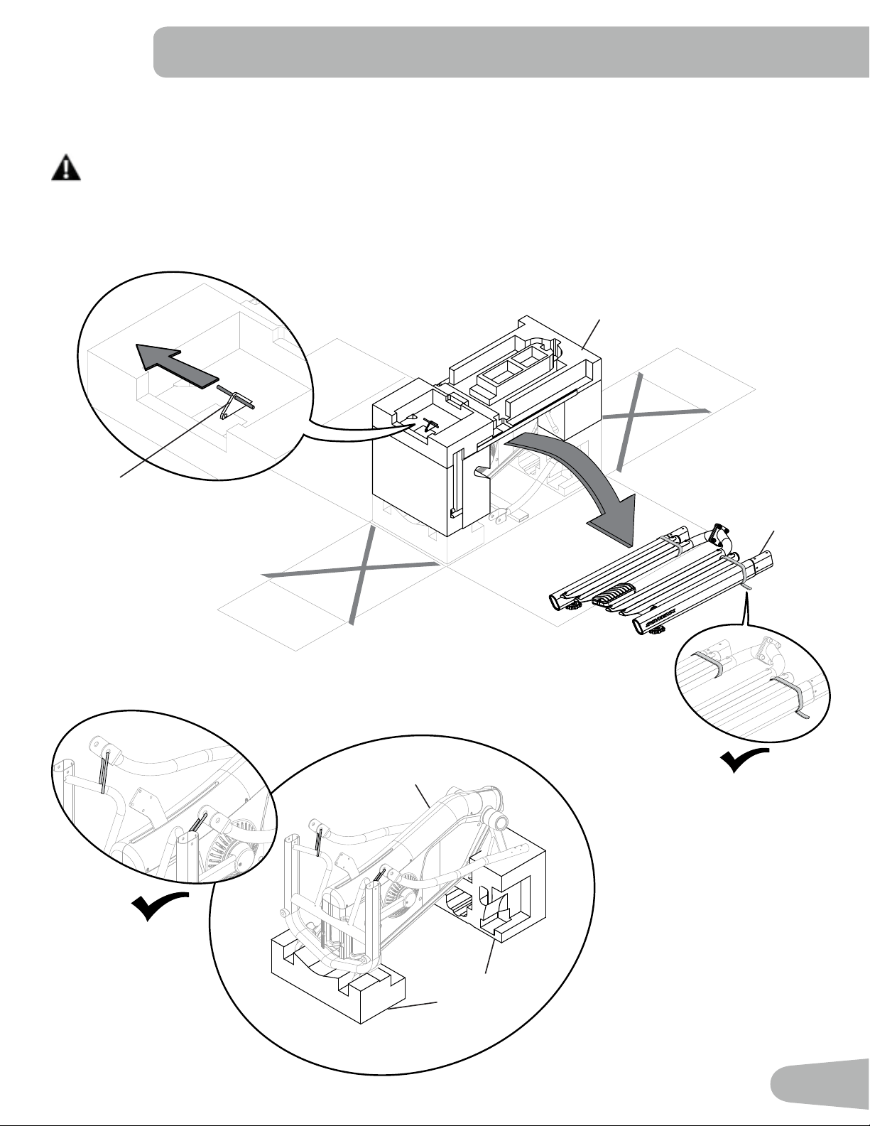
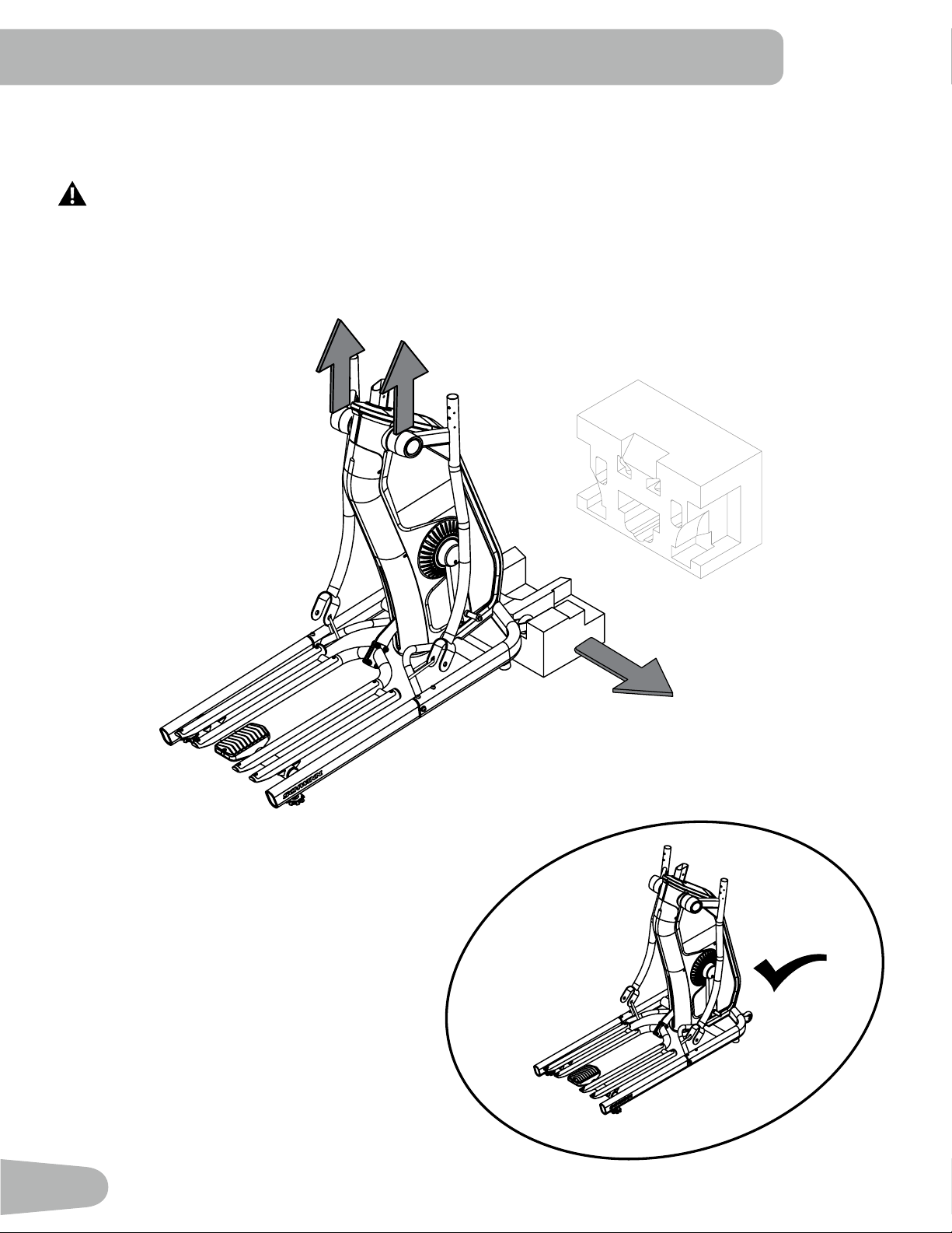
2. Keeping the Area Clear Along the Short Ends of the Box, Unpack Leaving the Main
Assembly on the Two Lower Shipping Blocks
DO NOT CUT THE SHIPPING ZIP-TIES on the Rail Assembly or Main Assembly until instructed.
Note: Be sure to remove the Shipping Insert Rod from the Incline (Lift) Motor Arm of the Main Assembly before remov-
ing the Upper Shipping Block.
5
12
Lower Shipping
Blocks
Incline (Lift) Motor Arm
Upper Shipping Block
14
12
X4
*
X4
6mm
*
6mm
X8
A
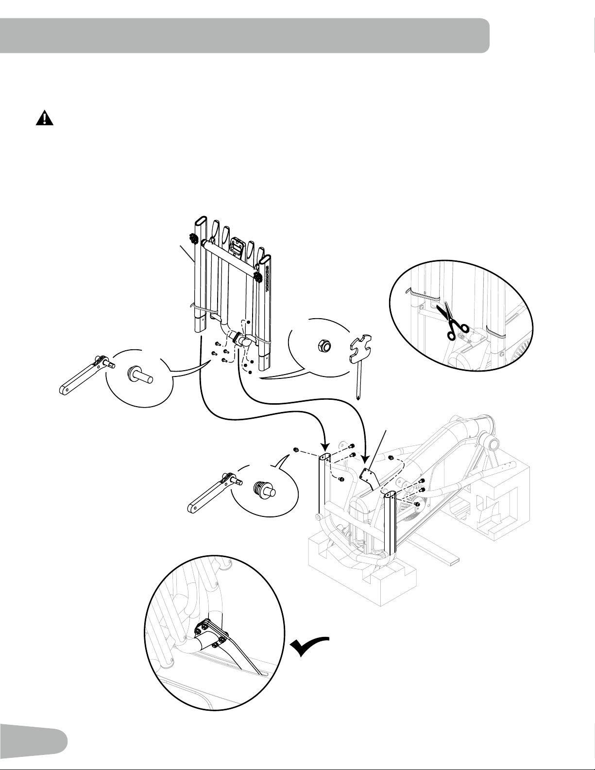
3. Attach the Rail Assembly to the Main Assembly. Once attached, cut the Shipping Zip-Ties
from the Rail Assembly and Attach to the Incline (Lift) Motor Arm of the Main Assembly.
In order to avoid possible serious injury, when attaching the Rail Assembly to the Main Assembly be
careful to avoid ngers or hands being caught or pinched. Do not place ngers or hands below any
pivoting parts of the Rail Assembly.
Note: Some parts can be slightly shifted to assist with alignment. At first, only finger tighten hardware. Then with all of
hardware started, FULLY tighten. * Hardware is not supplied in the Hardware Bag. Remove all hardware from
the Rail Assembly before attaching it.
Incline (Lift)
Motor Arm
15
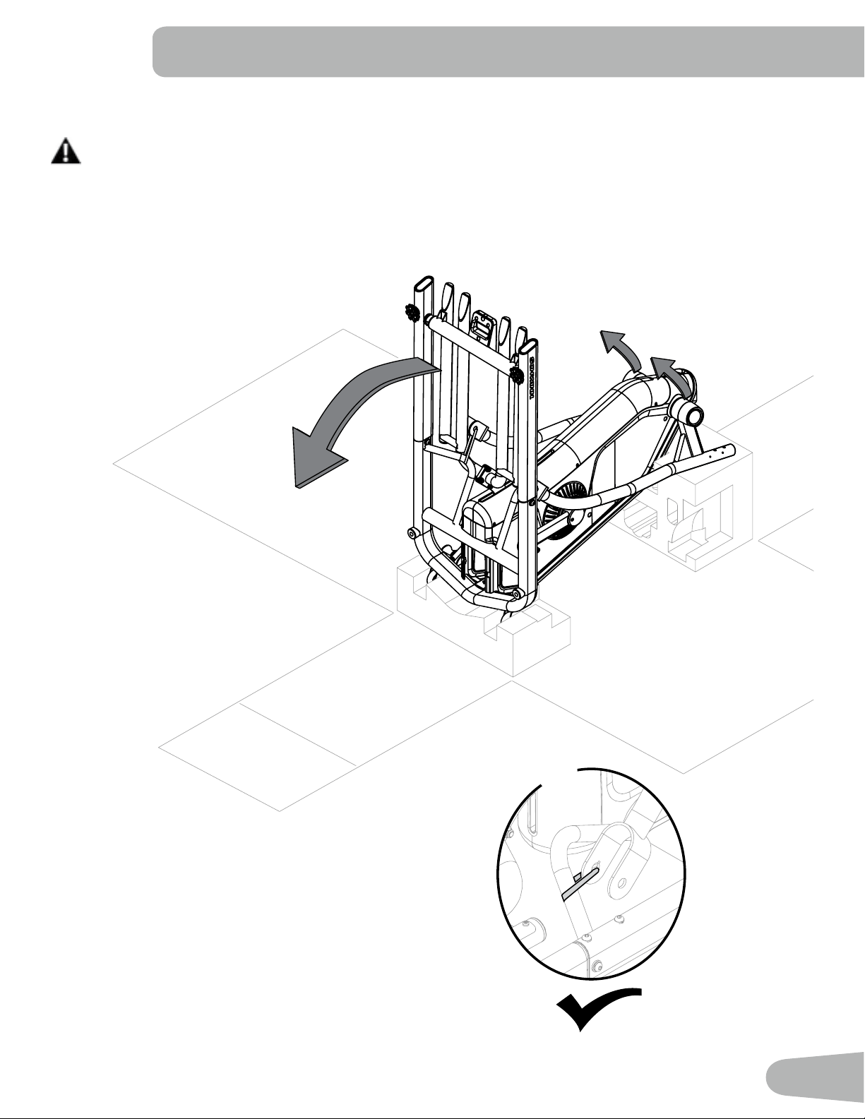
4. Safely Pivot the Frame Assembly into an Upright Position
Some components of the machine can be heavy or awkward. Use a second person when doing the assem-
bly steps involving these parts. Do not do steps that involve heavy lifting or awkward movements on your
own. Have a second person assist by lowering the Rail Assembly.
Note: This step may require two people. DO NOT CUT the Shipping Zip-Ties that secure the Lower Handlebars
until instructed to cut them.
X2
16
5. Slightly Lift the Frame Assembly and Remove the Shipping Block from Under It. Gently
Lower the Frame Assembly.
Some components of the machine can be heavy or awkward. Use a second person when doing the assem-
bly steps involving these parts. Do not do steps that involve heavy lifting or awkward movements on your
own. Lift the Frame Assembly from the inside pivot area as indicated below.
17
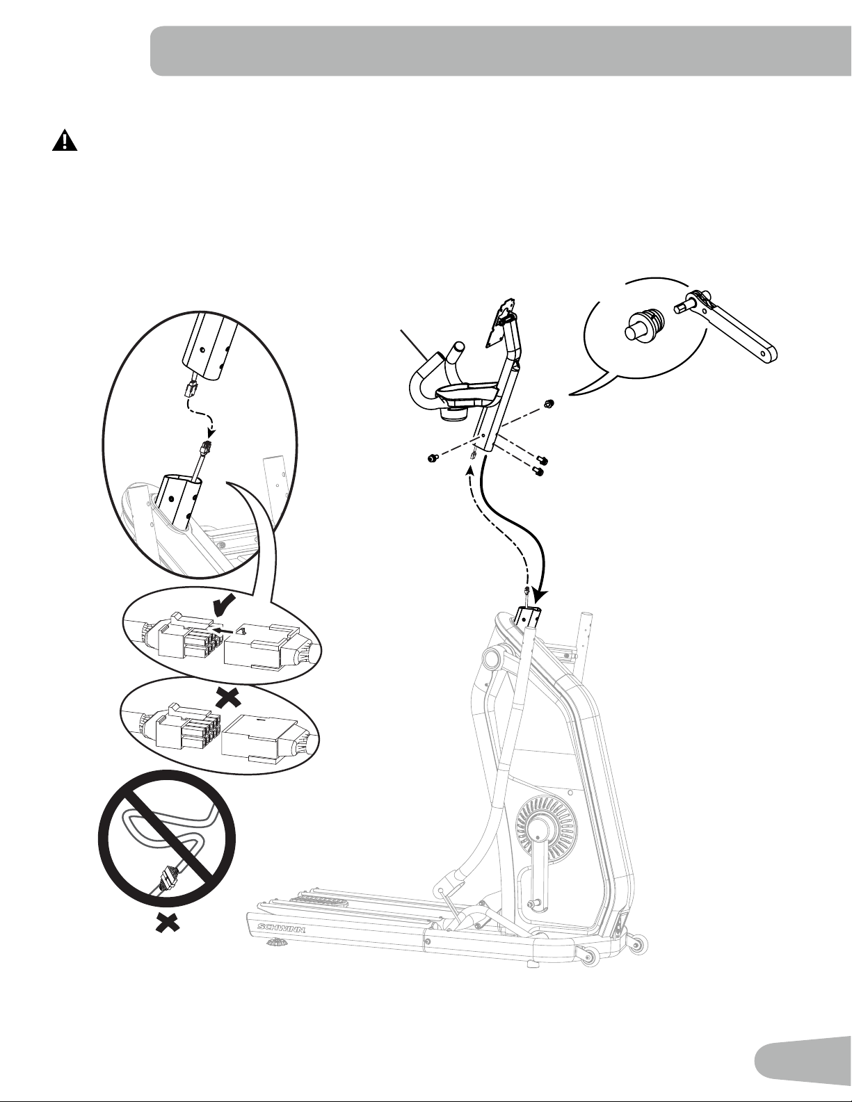
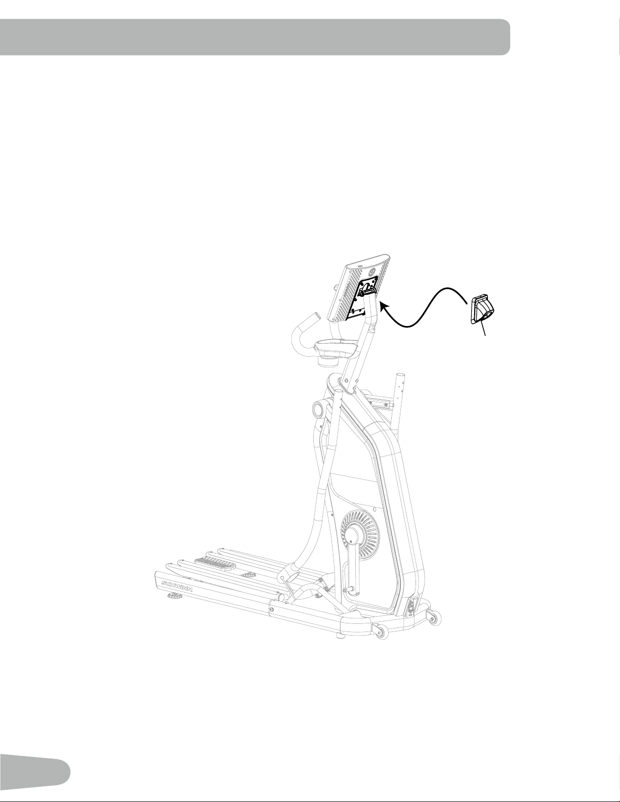
6. Connect the Cables, and Then Attach the Console Mast to the Frame Assembly
Some components of the machine can be heavy or awkward. Use a second person when doing the assembly
step involving these parts. Do not do steps that involve heavy lifting or awkward movements on your own.
Note: Do not pinch or cut the Cables. To assist with not pinching, gently pull the cables from the top of the Console Mast
as it is lowered onto the Frame Assembly.
X4
6mm
A
6
18
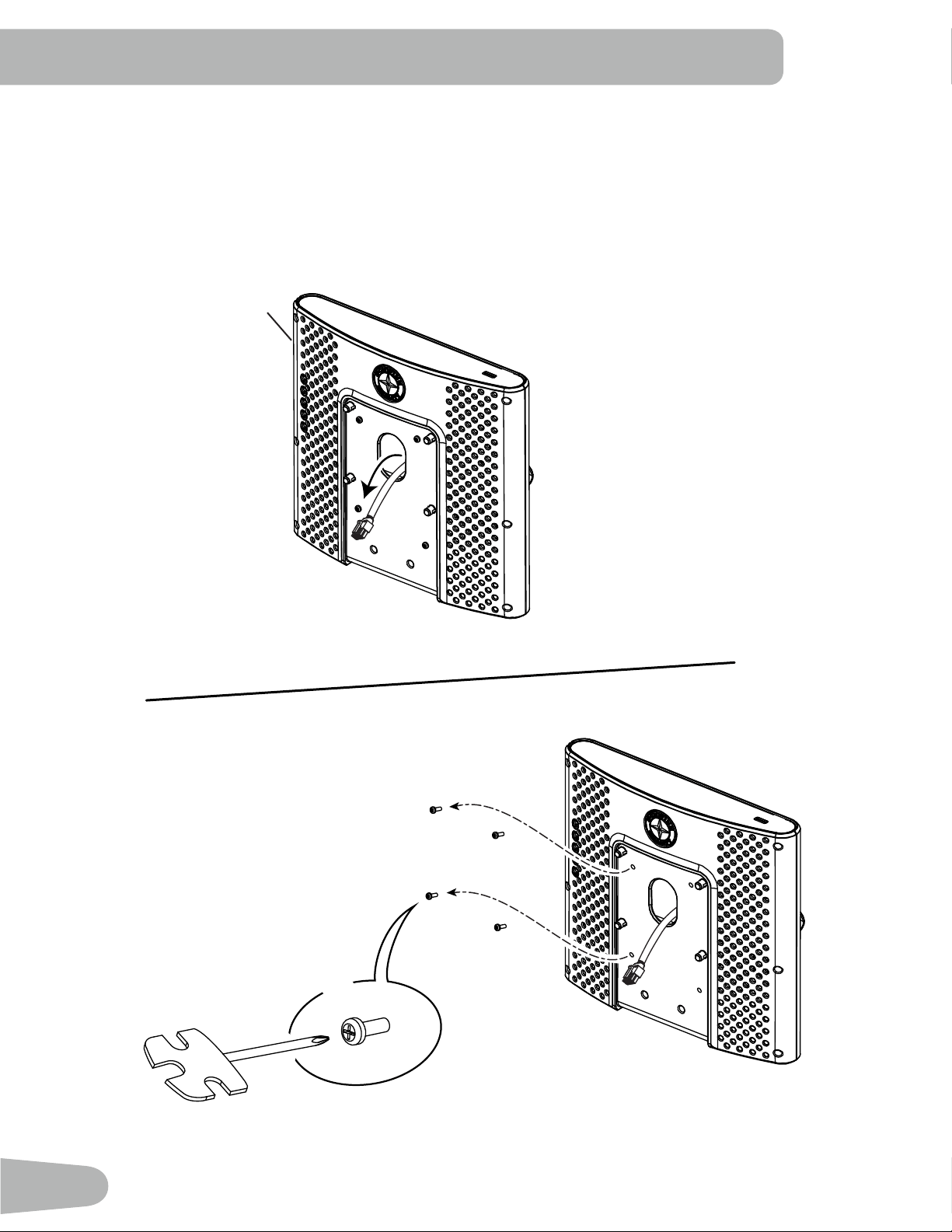
7. From the Opening on the Back of the Console Assembly, Gently Remove the Loose End
of the Cable from the Console Assembly. Then Remove the Hardware from the Console
Assembly.
NOTICE: Do not pinch or cut the Cable. Do not allow the hardware to fall into the Console Assembly. * Hardware is
not supplied in the Hardware Bag.
*
1
X4
#2
19
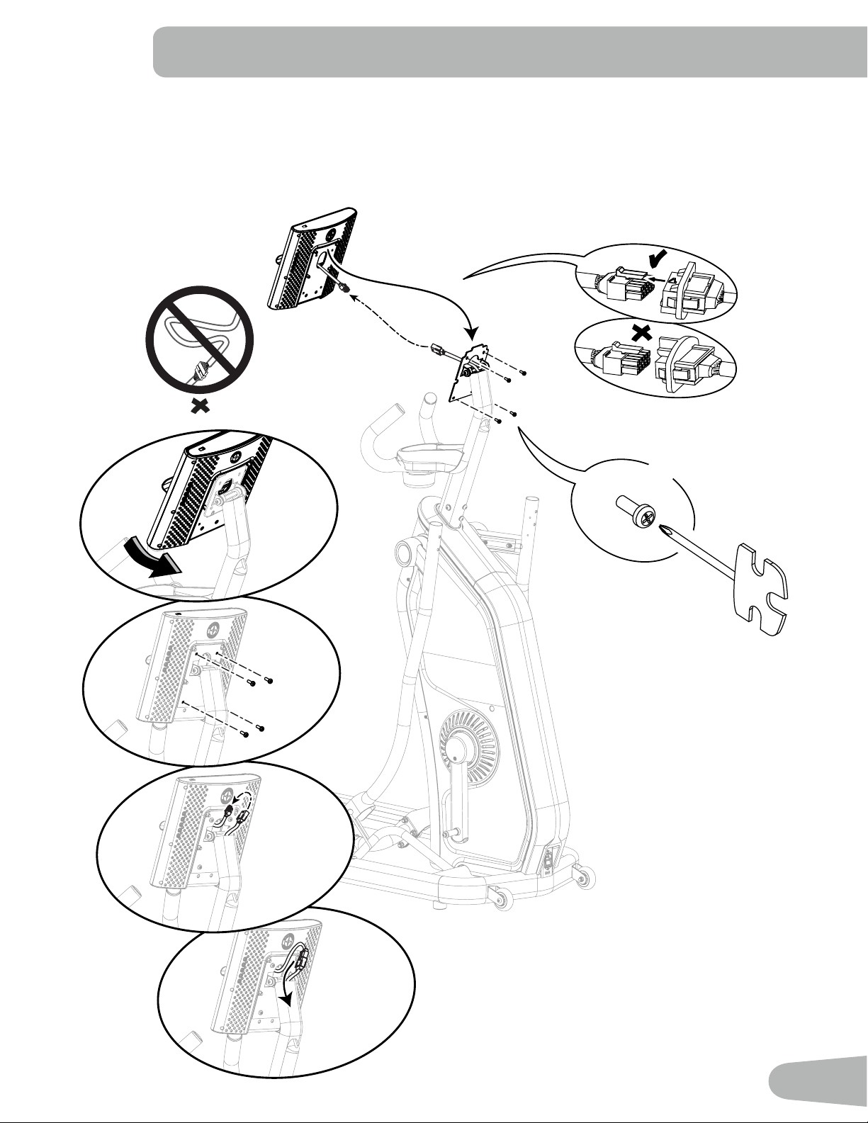
8. Place, Pivot and Secure the Console Assembly to the Console Mast, and Then Connect the
Console Cables
NOTICE: Do not pinch or cut the Cables. Be sure to fully connect the cable connectors. Once connected, push the
Cables into the Console Mast. * Hardware is not supplied in the Hardware Bag.
#2
*
X4
*
*
*
*
20
9. Attach the Console Pivot Cover to the Frame Assembly.
7
21
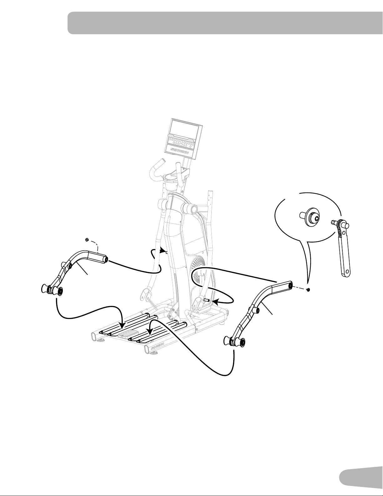
10. Attach the Legs to the Frame Assembly
Note: Do not cut the Shipping Zip-Ties. Lubricant has been applied to some of the hardware involved with this step.
Be sure to have a cloth or paper towel available to wipe any excess lubricant o of your hands after installa-
tion. * Hardware is not supplied in the Hardware Bag.
X2
*
10
13
6mm
22
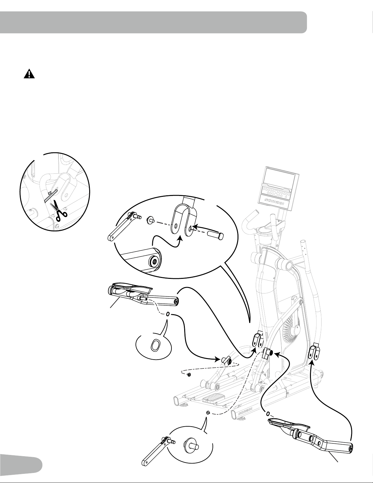
11. Cut the Shipping Zip-Ties that Secure the Lower Handlebars. Attach the Pedals to the
Frame Assembly.
In order to avoid possible serious injury, when inserting the end of the Pedal into the Lower Handlebar be
careful to avoid ngers or hands being caught or pinched. Be sure to stay out of the path of the
Handlebars.
Note: Do not fully rotate the Lower Handlebars or damage to the cables in the Handlebars will occur. When
inserting the Pedals into the Legs, be sure that the post is centered with the opening of the Leg. Lubricant has
been applied to some of the hardware involved with this step. Be sure to have a cloth or paper towel available to
wipe any excess lubricant off of your hands after installation. * Hardware is not supplied in the Hardware Bag.
** Using the 19mm wrench, slightly rotate the Pivot Pin to assist with a proper set. Be sure the key on the Pivot
Pin is fully set into the notch on the Lower Handlebar. The Pivot Pin will be flush with the outside of the Lower
Handlebar when properly set.
X2
*
11
14
6mm
X2
*
X2
X2
**
B
6mm
C
23
X8
A
6mm
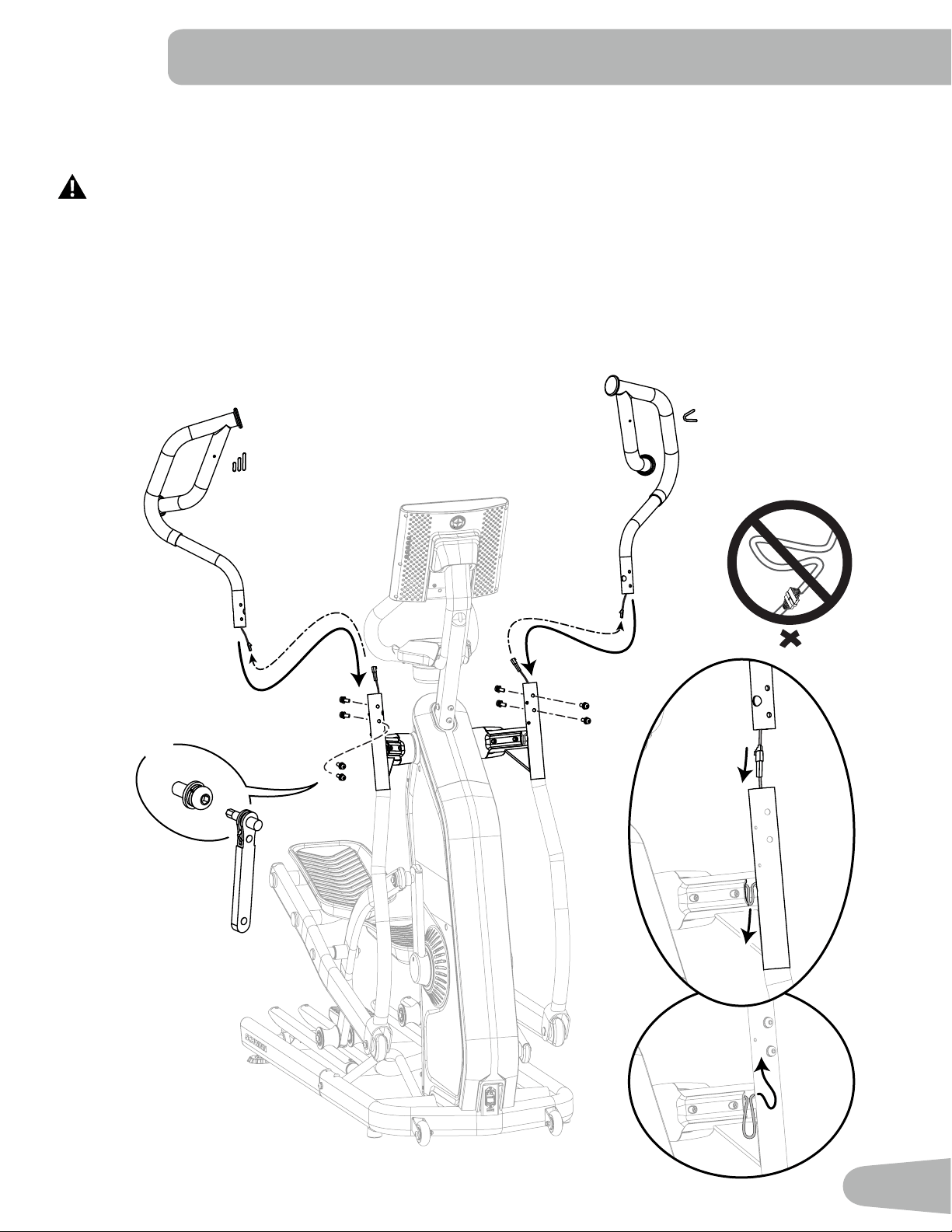
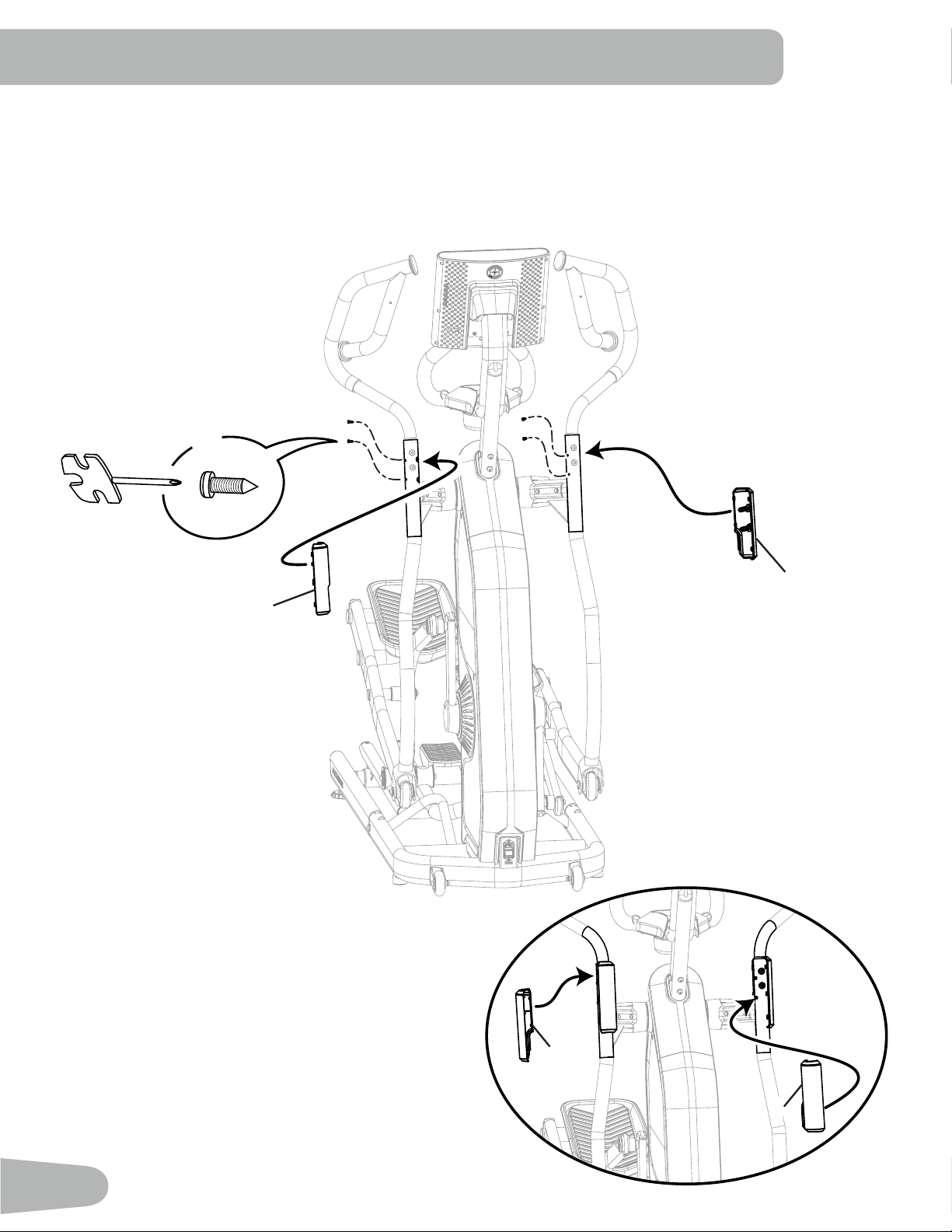
12. Connect the Cables. While Inserting the Upper Handlebar, Gently Pull the Cable Down into
the Lower Handlebar, and Attach the Upper Handlebar.
In order to avoid possible serious injury when inserting the tube ends onto the Lower Handlebars, be
careful to avoid ngers or hands being caught or pinched.
Some components of the machine can be heavy or awkward. Use a second person when doing the assembly
step involving these parts. Do not do steps that involve heavy lifting or awkward movements on your own.
Note: Do not pinch or cut the Cables. When the Upper Handlebars are attached, push the exposed cables back into the
Upper Handlebars as far as possible without damaging them. A decal has been applied to all right (“ R ”) and left
(“ L ”) parts to assist with assembly.
“ Resistance “
“ Incline “
24
13. Attach the Interior Handlebar Covers, and then Snap the Exterior Handlebar Covers to the
Frame Assembly
Note: Do not pinch or cut the Cables inside the Handlebars. Before installing hardware, inspect to be sure that the hard-
ware will not cut any of the cables inside the Handlebars. If necessary, adjust the cables and inspect again.
X4
D
3
3
4
4
#2
25
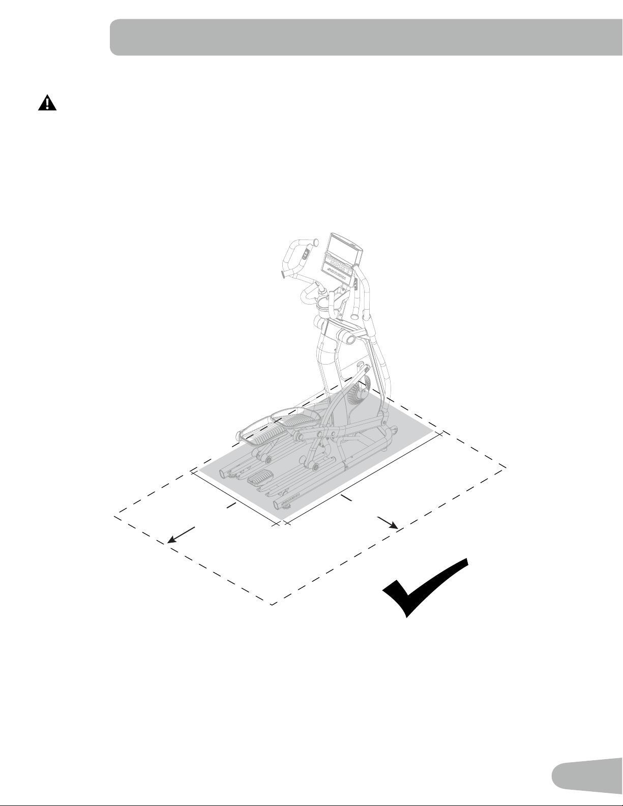
14. Clear a Path to the Intended Workout Area
For safe operation, the Intended Workout Area must be on a hard, level surface. Allow a minimum workout
area of 2.1 m x 1.5 m (82.1 in x 57.9 in). Keep the workout area clear 0.6 m (24 in) along the side used to
access the machine and to the rear of the machine. This is the recommended safe distance for access and
passage around and emergency dismounts from the machine. Be sure that the workout space you are
utilizing has adequate height clearance, taking into consideration the height of the user and the maximum
incline of the machine. Keep third parties out of this space when machine is in use.
0.6 m (24 in)
0.6 m (24 in)
86.2 cm
(33.9 in)
147.6 cm
(58.1 in)
1.5 m (57.9 in)
2.1 m (82.1 in)
26
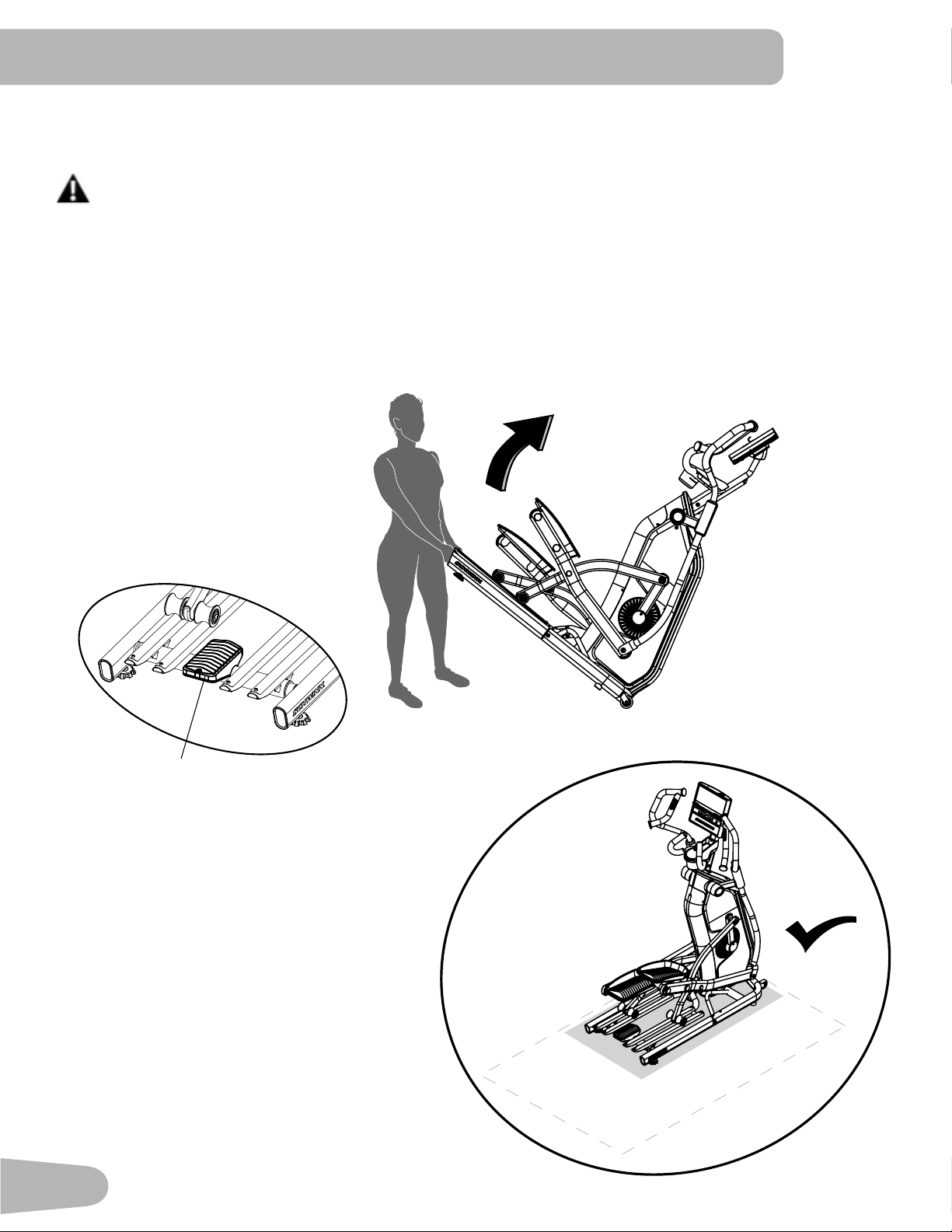
15. Using the Transport Handle Tilt the Machine onto the Transport Wheels, and Then Safely
Roll and Lower It into the Intended Workout Area
Do not use the handlebars, Console Mast, or the Console to lift or move the machine. Injury to you or
damage to the machine can occur.
The machine may be moved by one or more persons depending on their physical abilities and capacities.
Make sure that you and others are all physically t and able to move the machine safely.
Place the machine on a clean, hard, level surface, free from unwanted material or other objects that may
hamper your ability to move freely. A rubber mat should be used below the machine to prevent the release
of static electricity and protect your ooring.
Transport Handle
27
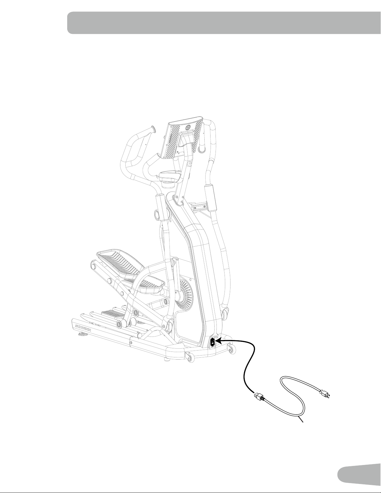
16. Connect the Power Cord to the Frame Assembly
Note: Make sure the Power Cord is pushed all the way into the Power Inlet on the machine.
9
28
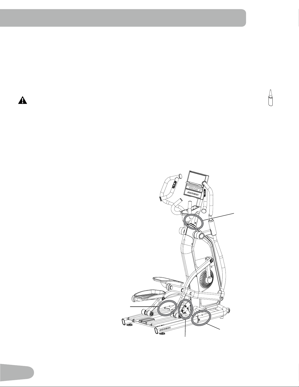
17. Final Inspection
Inspect your machine to ensure that all fasteners are tight and components are properly assembled.
Be sure to record the serial number in the eld provided at the front of this manual.
Carefully remove the protective plastic film from the display screen, keypad and top of the Console. Due to static electricity,
“ghost” images may show on the screen but these will disappear after a few minutes.
Apply a small amount of silicone lubricant to a cloth and wipe the Rails to eliminate roller noise.
Silicone lubricant is not intended for human consumption. Keep out of reach of children.
Store in a safe place.
Do not use until the machine has been fully assembled and inspected for correct
performance in accordance with the Owner’s Manual.
14
3
2
4
7
8
4
9
3
5
10
11
12
13
1
6
15
16
*
*
*
*
17
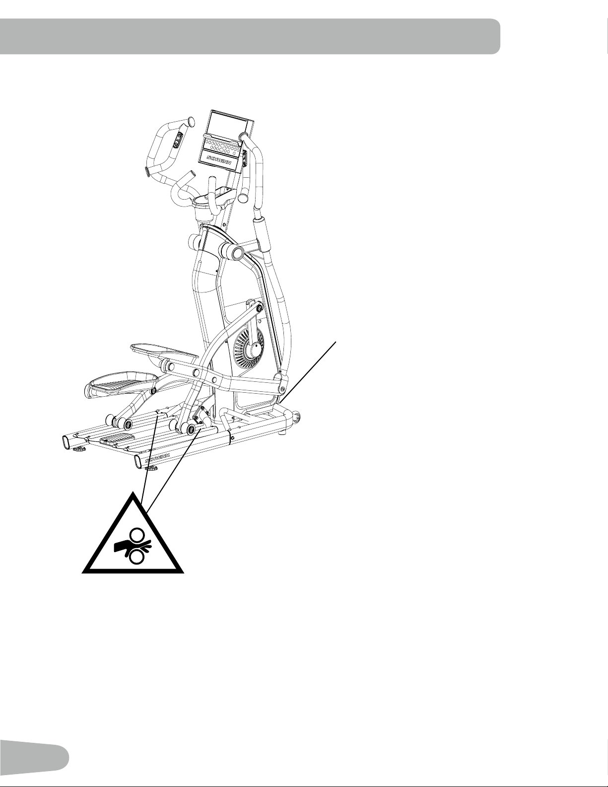
NOTICE: After your rst few workouts, some
hardware will need to be tightened
again. To ensure quiet and smooth
operation, make sure to tighten
the indicated hardware after three
workouts.
Be sure to inspect and fully tighten
all hardware monthly or after every
20 hours of use.
Console Mast
Rail Assembly
Incline (Lift) Motor
Arm
Rail Assembly

29
BEFORE YOU START
* A JRNY™ membership is required for the JRNY™ experience – see www.schwinntness.com/jrny for details. For
United States and Canada customers, you can obtain a JRNY™ membership by calling 888-986-5528 or visiting
www.schwinntness.com/jrny. Where available (including the United States), you can also obtain a JRNY™ membership
by downloading the JRNY™ app onto your phone or tablet and signing up within the downloaded app. JRNY™
memberships may not be available in all countries.
Using the “JRNY™” App with Your Machine
This tness machine is equipped with Bluetooth
®
connectivity and can be wirelessly connected for workouts using the
“JRNY™” app. The app can be accessed with your JRNY™ membership.
Note: Do not connect this machine through your Bluetooth
®
settings on your device. Simply download the app, start a
workout, and follow the instructions on the app.
1. Download the app named JRNY
™
. The app is available on the App Store and Google Play™.
Note: For a complete list of supported devices, review the app on the App Store or Google Play™.
2. Install the app.
3. Open the “JRNY™” app, and follow the instructions.
4. When done, tap on the red Bluetooth
®
icon in the upper right corner of the display.
Note: If Bluetooth
®
is not active on your device, follow the instructions to activate it.
5. A list of available machines will be displayed. Select your machine from the list of available machines.
6. The JRNY™ app is now ready for use.
Note: Once a Bluetooth
®
Heart Rate device is connected, that device is engaged to that machine. To use the Heart
Rate device elsewhere, it must be disconnected. Follow the instructions provided in the app to disconnect.
Bluetooth
®
Low Energy (BLE) Heart Rate Monitor (not supplied)
Your tness machine is equipped to be able to receive a signal from a Bluetooth
®
Low Energy (BLE) Heart Rate (HR)
Monitor. When connected, the Console will display the Bluetooth
®
Heart Rate Monitor Connected icon. Follow the
instructions provided with your Bluetooth
®
Low Energy (BLE) Heart Rate Monitor.
If you have a pacemaker or other implanted electronic device, consult your doctor before using a Bluetooth
®
Heart Rate Monitor.
Note: Be sure to remove the protective cover (if provided) from the Heart Rate Sensor before use.
1. Put on your Bluetooth
®
Low Energy (BLE) Heart Rate monitor and activate it.
2. The Console will actively search for any monitors in the area, and will rapidly ash the Bluetooth
®
Heart Rate Monitor
Connected icon.
Note: Any previously connected HR devices will be disconnected. However, if they are within range, the Console
may nd them again if unable to locate your Monitor.
3. When connected, the Bluetooth
®
Heart Rate Monitor Connected icon will ash with your pulse and your current heart
rate value will be displayed on the Console. You are now ready to workout.
Note: Once a Bluetooth
®
Low Energy (BLE) Heart Rate device is connected, that device is engaged to that machine.
To use the Heart Rate device elsewhere, it must be disconnected. Follow the instructions in the app, or push
the Connect Bluetooth
®
button to disconnect from the Console.
30
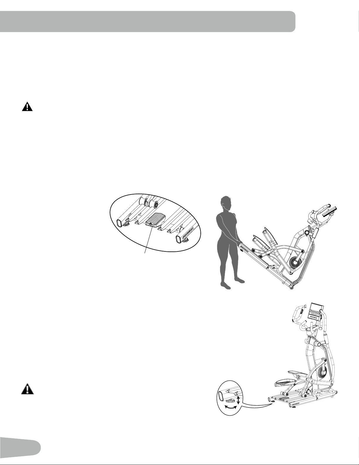
Moving the Machine
Use the Transport Handle / Rear Step and Transport Wheels to move the machine. The Transport Handle / Rear Step is
located in the middle of the Rail Assembly at the rear of the machine. Tilt the machine forward by lifting upward with the
Transport Handle / Rear Step until the weight is on the Transport Wheels.
Roll the machine on the transport wheels to a new location. Lower your machine slowly into its new location without injury
to your head or ngers.
Do not use the handlebars, Console Mast, or the Console to lift or move the machine. Injury to you or
damage to the machine can occur.
The machine may be moved by one or more persons depending on their physical abilities and capacities.
Make sure that you and others are all physically t and able to move the machine safely.
Place the machine on a clean, hard, level surface, free from unwanted material or other objects that may
hamper your ability to move freely. A rubber mat should be used below the machine to prevent the release
of static electricity and protect your ooring.
To prevent unsupervised operation of the machine always turn the power switch to O and disconnect the
power cord from the wall outlet and machine power input. Place the power cord in a secure location.
Leveling the Machine
The machine needs to be leveled if your workout area is uneven or if
the Rail Assembly is slightly o the oor. To adjust:
1. Place the machine in your workout area.
2. Safely stand on the Rear Step for approximately 20 seconds.
3. Step o the machine.
4. Loosen the locking nuts and adjust the levelers until they all contact
the oor.
Do not adjust the levelers to such a height that they detach
or unscrew from the machine. Injury to you or damage to
the machine can occur.
5. Adjust until the machine is level. Tighten the locking nuts.
Make sure the machine is level and stable before you exercise.
Transport Handle / Rear Step
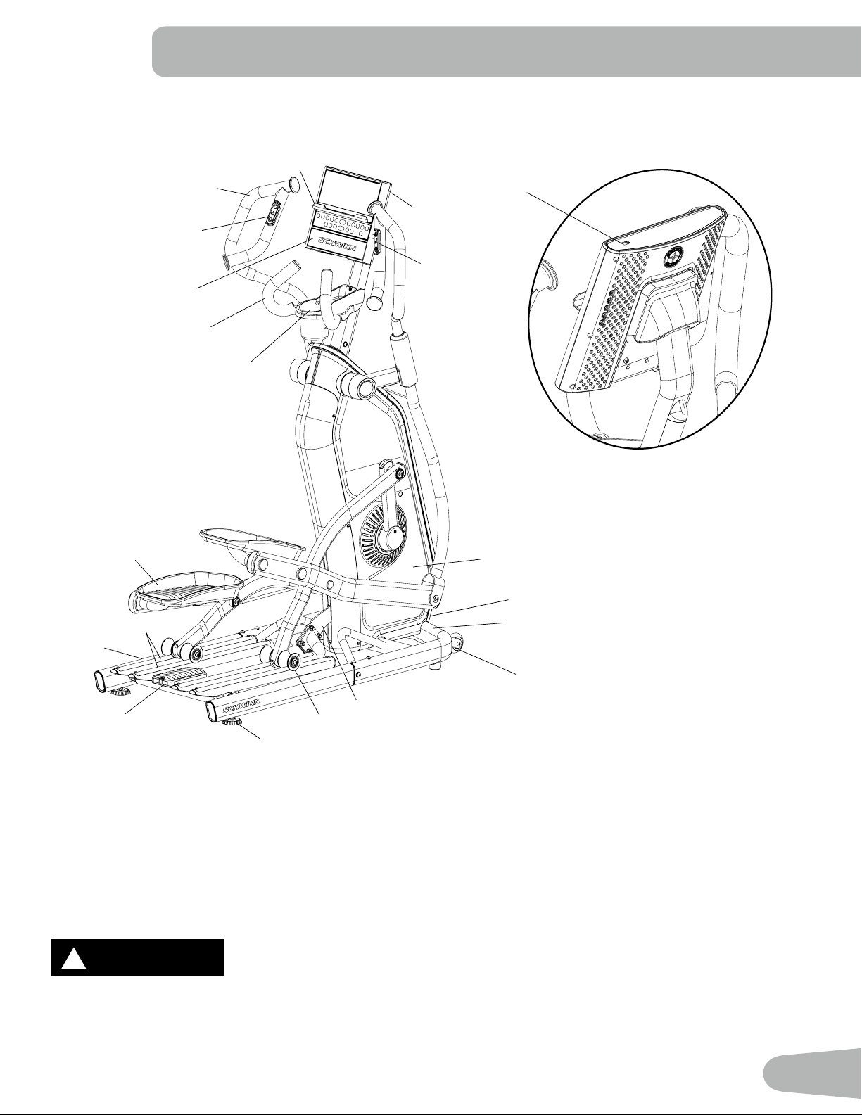
31
Pedal
Transport Handle / Rear
Step
Leveler
Rail Assembly
Media Tray
Upper Handlebar
Speaker
Power Switch / Inlet
USB Charging Port
WARNING
!
WARNING indicates a hazardous
situation which, if not avoided, could
result in death or serious injury.
DANGER
!
DANGER indicates a hazardous
situation which, if not avoided, will
result in death or serious injury.
CAUTION
!
CAUTION indicates a hazardous
situation which, if not avoided, could
result in minor or moderate injury.
NOTICE
NOTICE is used to address practices
not related to personal injury.
!
Use the values calculated or measured by the machine’s computer for reference
purposes only. The heart rate displayed is an approximation and should be used for
reference only. Over exercising may result in serious injury or death. If you feel faint
stop exercising immediately.
Incline (Lift) Motor Arm
Resistance Re-
mote Controls
Incline Remote Controls
Console, Tiltable
Static Handlebar
Fully Shrouded Flywheel;
Transport Wheel
Front Stabilizer
Storage Tray / Water
Bottle Holder
FEATURES
Roller
Rail
32
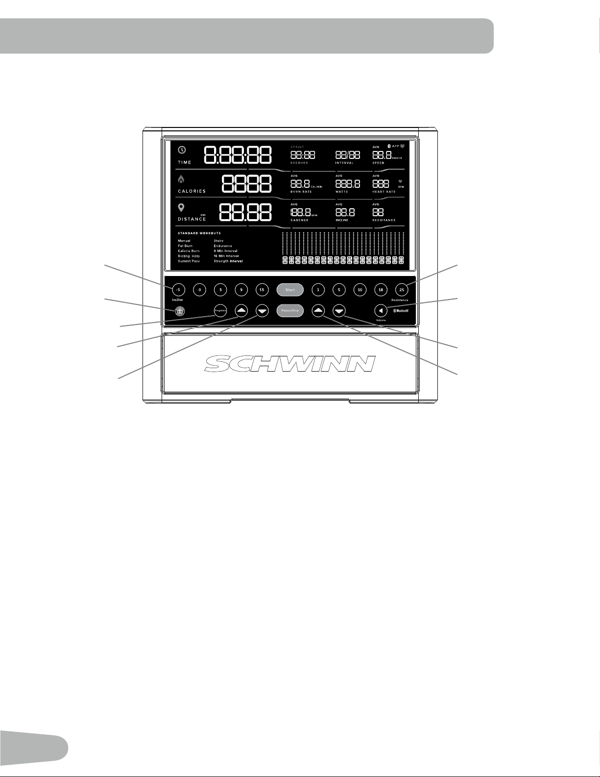
Keypad Functions
Incline Level Quick buttons- Shifts the incline level to the setting quickly during a workout.
Resistance Level Quick buttons- Shifts the resistance level to the setting quickly during a workout.
Programs button- Tap to cycle through the menu of workout programs.
Start button- Starts a Program workout, conrms information, or resumes a paused workout.
Pause / Stop button- Pauses an active workout or ends a paused workout.
Increase () button- Increases the workout resistance or incline level, or moves through options.
Decrease () button- Decreases the workout resistance or incline level, or moves through options.
Volume button- Sets the sound level of the Console. Tap to cycle through the volume levels: O, 1, 2 (default), 3. It does
not aect the output from your personal device.
Reset button (Schwinn
™
logo)- for service technician use only. When pushed during power up, the button restores the
Console settings to the factory default state. The Console will require updates to be applied in order to become fully
functional. Workout data is not aected.
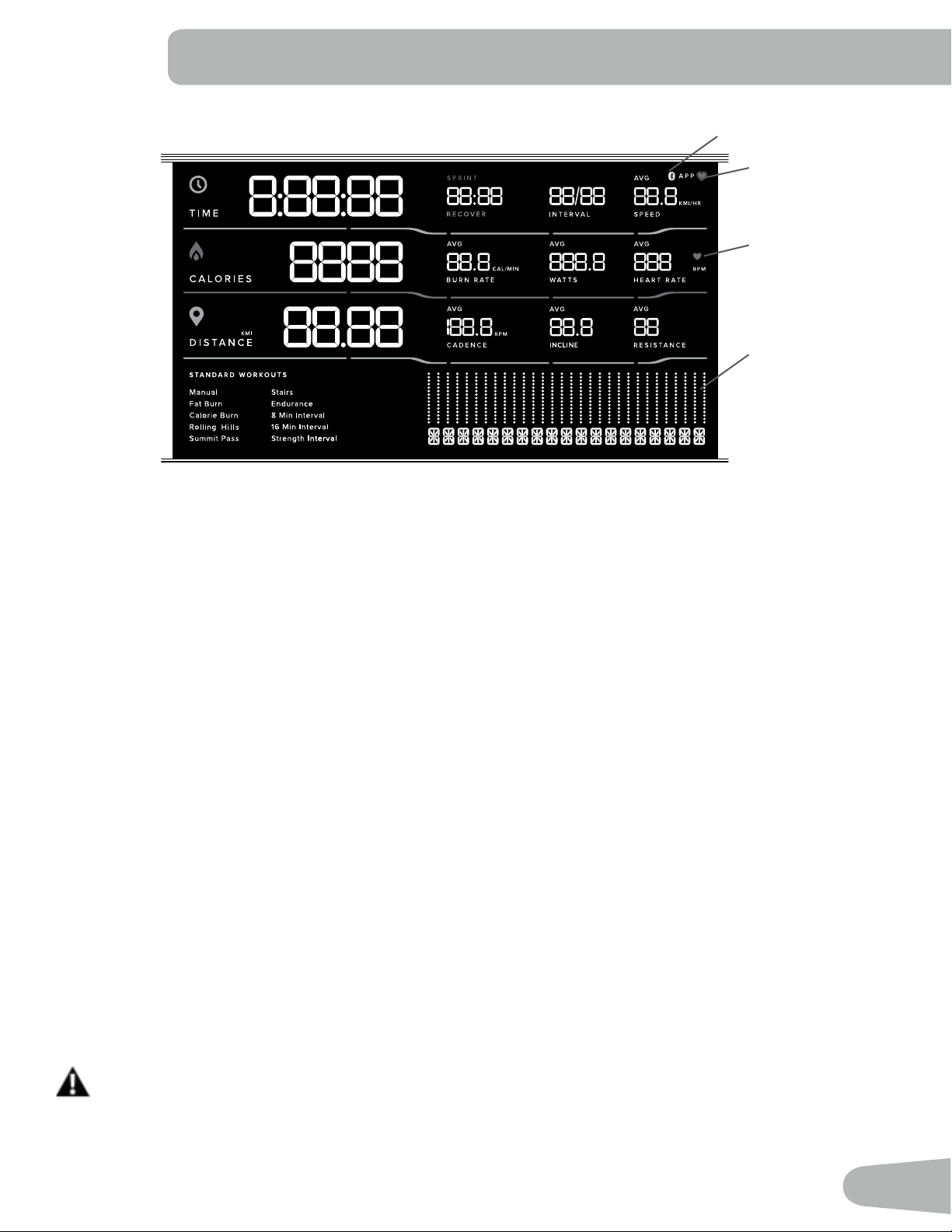
Console Display
Bluetooth
®
App Connected icon - Display shows when the Console is paired with the App.
Bluetooth
®
Heart Rate Monitor Connected icon - Display shows when the Console is paired with a Bluetooth
®
Heart Rate
Monitor.
Console Features
The Console provides important information about your workout and lets you control the incline and resistance levels
while you exercise. The Console features touch control buttons to navigate you through the exercise programs.
Reset button
™
Incline Level Quick
buttons
Resistance Level
Quick buttons
Increase button
(Resistance)
Decrease button
(Resistance)
Volume button
Programs button
Increase button
(Incline)
Decrease button
(Incline)
33
Heart Rate Detected icon - Display shows when the Console receives a heart rate signal from a Bluetooth
®
Heart Rate
Monitor.
Time
The TIME display shows the total time count of the workout.
Interval
During an Interval workout, the INTERVAL display shows the currently active Interval and the total number of Intervals for
the workout. Each Interval has a Sprint and a Recover workout segment.
Speed
The SPEED display shows the machine speed in miles per hour (mph) or kilometers per hour (km/h).
Calories
The CALORIES display shows the estimated calories that you have burned during the exercise.
Burn Rate
The BURN RATE display shows the level of calories being burned per minute. This rate is a function of intensity, which
is the current level of RPM (pedal speed) and resistance level. As either of those values increase, the Burn Rate will
increase.
Watts
The WATTS display shows the estimated power output at the current RPM and intensity level, displayed in watts (746
watts = 1 hp).
Heart Rate (Pulse)
The HEART RATE display shows the beats per minute (BPM) from the heart rate monitor. When a heart rate signal is
received by the Console, the icon will ash.
Consult a physician before you start an exercise program. Stop exercising if you feel pain or tightness in
your chest, become short of breath, or feel faint. Contact your doctor before you use the machine again.
The heart rate displayed is an approximation and should be used for reference only.
Program Display
™
Bluetooth
®
App Connected icon
Bluetooth
®
Heart
Rate Monitor
Connected icon
Heart Rate
Detected icon

34
Distance
The DISTANCE display shows the distance count (miles or km) in the workout. The maximum distance value is 99.99.
The default distance unit is miles (MI).
Note: To switch units between kilometers and miles before a workout, push the Programs button and hold for 3 seconds
to enter the Console Setup Mode. The System Units prompt appears. Push an Increase/Decrease button to
change the units (KM/KG or MI/LB). With the desired unit of measurement displayed, push the Start button to
save.
Cadence
The CADENCE display shows your current pedal speed in revolutions per minute (RPM).
Interval
The INTERVAL display shows the current interval level in the workout.
Incline
The INCLINE display shows the current incline level in the workout.
Resistance
The RESISTANCE display shows the current resistance level in the workout.
Program Display
The Program Display shows information to the User and the grid display area shows the course prole for the program.
Each column in the prole shows one interval (workout segment). The higher the column, the higher the resistance level.
The ashing column shows your current interval.
Remote Incline and Resistance Controls
The Remote Incline and Resistance Controls are located on the Upper Handlebar Arms. The incline and resistance can
be controlled from these controls. The buttons on the left Upper Handlebar include an Incline Increase button () and an
Incline Decrease () button. The controls on the right Upper Handlebar include a Resistance Increase button () and a
Resistance Decrease () button.
Do not push these buttons when grabbing onto the Upper Handlebar Arms.
Using the “JRNY™” App with Your machine
This tness machine is equipped with Bluetooth
®
connectivity and can be wirelessly connected for workouts using the
“JRNY™” app. The app can be accessed with your JRNY™ membership.
Note: Do not connect this machine through your Bluetooth
®
settings on your device. Simply download the app, start
a workout, and follow the instructions on the app.
1. Download the app named JRNY
™
. The app is available on the App Store and Google Play™.
Note: For a complete list of supported devices, review the app on the App Store or Google Play™.
* A JRNY™ membership is required for the JRNY™ experience – see www.schwinntness.com/jrny for details. For
United States and Canada customers, you can obtain a JRNY™ membership by calling 888-986-5528 or visiting
www.schwinntness.com/jrny. Where available (including the United States), you can also obtain a JRNY™ membership
by downloading the JRNY™ app onto your phone or tablet and signing up within the downloaded app. JRNY™
memberships may not be available in all countries.

35
2. Install the app.
3. Open the “JRNY™” app, and follow the instructions.
4. When done, tap on the red Bluetooth
®
icon in the upper right corner of the display.
Note: If Bluetooth
®
is not active on your device, follow the instructions to activate it.
5. A list of available machines will be displayed. Select your machine from the list of available machines.
6. The JRNY™ app is now ready for use.
Note: Once a Bluetooth
®
Heart Rate device is connected, that device is engaged to that machine. To use the Heart
Rate device elsewhere, it must be disconnected. Follow the instructions provided in the app to disconnect.
USB Charging
If a USB Device is attached to the USB Port, the Port will attempt to charge the device. The power supplied from the USB
Port may not be enough to operate the device and charge it at the same time.
Bluetooth
®
Audio (Input)
Your machine is able to play audio across a Bluetooth
®
connection from your smart device through the console speakers.
Note: Bluetooth
®
audio can only be streamed into the console.
Bluetooth
®
Low Energy (BLE) Heart Rate Monitor (not supplied)
Your tness machine is equipped to be able to receive a signal from a Bluetooth
®
Low Energy (BLE) Heart Rate (HR)
Monitor. When connected, the Console will display the Bluetooth
®
Heart Rate Monitor Connected icon. Follow the
instructions provided with your Bluetooth
®
Low Energy (BLE) Heart Rate Monitor.
If you have a pacemaker or other implanted electronic device, consult your doctor before using a
Bluetooth
®
Heart Rate Monitor.
Note: Be sure to remove the protective cover (if provided) from the Heart Rate Sensor before use.
1. Put on your Bluetooth
®
Low Energy (BLE) Heart Rate monitor and activate it.
2. The Console will actively search for any monitors in the area, and will rapidly ash the Bluetooth
®
Heart Rate Monitor
Connected icon.
Note: Any previously connected Heart Rate devices will be disconnected. However, if they are within range, the
Console may nd them again if unable to locate your Monitor.
3. When connected, the Bluetooth
®
Heart Rate Monitor Connected icon will ash with your pulse and your current heart
rate value will be displayed on the Console. You are now ready to workout.
Note: Once a Bluetooth
®
Low Energy (BLE) Heart Rate device is connected, that device is engaged to that machine.
To use the Heart Rate device elsewhere, it must be disconnected. Follow the instructions provided in the app
to disconnect.
36
Heart Rate Calculations
Your maximum heart rate usually decreases from 220 Beats Per Minute (BPM) in childhood to approximately 160 BPM by
age 60. This fall in heart rate is usually linear, decreasing by approximately one BPM for each year. There is no indication
that training inuences the decrease in maximum heart rate. Individuals of the same age could have dierent maximum
heart rates. It is more accurate to nd this value by getting a stress test than by using an age related formula.
Your at rest heart rate is inuenced by endurance training. The typical adult has an at rest heart rate of approximately 72
BPM, where as highly trained runners may have readings of 40 BPM or lower.
The Heart Rate table is an estimate of what Heart Rate Zone (HRZ) is eective to burn fat and improve your cardiovas-
cular system. Physical conditions vary, therefore your individual HRZ could be several beats higher or lower than what is
shown.
The most ecient procedure to burn fat during exercise is to start at a slow pace and gradually increase your intensity un-
til your heart rate reaches between 60 – 85% of your maximum heart rate. Continue at that pace, keeping your heart rate
in that target zone for over 20 minutes. The longer you maintain your target heart rate, the more fat your body will burn.
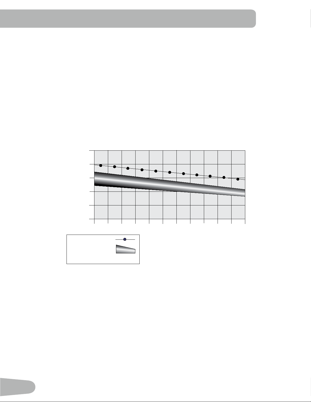
Fat-Burning Target Heart Rate
20-24
FAT-BURNING TARGET HEART RATE
Heart Rate BPM (beats per minute)
Age
25-29
0
50
100
150
200
250
30-34 35-39 40-44 45-49 50-54 55-59 60-64 65-69 70+
196
191
186
181
176
171
166
161
156
151
146
167
162
158
154
150
145
141
137
133
128
126
Maximum Heart Rate
Target Heart Rate Zone
(keep within this range
for optimum fat-burning)
118
115
112
109
106
103
100
97
94
91
88
The graph is a brief guideline, describing the generally suggested target heart rates based on age. As noted above, your
optimal target rate may be higher or lower. Consult your physician for your individual target heart rate zone.
Note: As with all exercises and fitness regimens, always use your best judgment when you increase your exercise
time or intensity.

37
What to Wear
Wear rubber-soled athletic shoes. You will need the appropriate clothes for exercise that allow you to move freely.
How Often Should You Exercise
Consult a physician before you start an exercise program. Stop exercising if you feel pain or tightness in
your chest, become short of breath, or feel faint. Contact your doctor before you use the machine again.
Use the values calculated or measured by the machine’s computer for reference purposes only. The heart
rate displayed on the console is an approximation and should be used for reference only.
• 3 times a week for 30 minutes each day.
• Schedule workouts in advance and try to follow the schedule.
• Consider doing some warm-up stretches, which will help prepare your body, before your workouts.
Mounting and Dismounting Your Machine
Care should be used when mounting or dismounting the machine.
Be aware that the Pedals and the Handlebars are connected and when either of these parts move the other
does as well. In order to avoid possible serious injury, grasp the Static Handlebars to steady yourself.
Be sure there is nothing under the Pedals before moving anything on the machine.
To mount your tness machine:
1. Move the Pedals so both are over the Rail Assembly, and not extended past the rear of the machine.
2. Grasp the Static Handlebars under the Console Assembly.
3. Steadying yourself with the Static Handlebars, step up onto the Transport Handle / Rear Step and the lowest Pedal.
As your weight is applied to the lowest Pedal, both Pedals will move. Be sure that the Pedals do not affect the leg on
the Transport Handle / Rear Step.
Note: “Bottomed out” is when the User is unable to start a workout because the Pedals will not move. If this occurs,
safely grasp the Static Handlebars and apply your weight to the heel of the higher foot. While still grasping
the Static Handlebar, lean back slightly applying more weight onto the heel. Once the Pedals begin to move,
resume your intended workout.
To dismount your tness machine:
1. Move the Pedals so both are over the Rail Assembly and bring the machine to a complete stop.
This machine is not equipped with a free-wheel. Pedal speed should be reduced in a controlled manner.
2. Grasp the Static Handlebars under the Console to steady yourself.
3. With your weight on the lowest foot, safely swing the upper foot o the Pedal and down onto the Transport Handle /
Rear Step. Be sure to place your foot on the Step so if the Pedals move, it will not affect your footing.
4. Swing the lower foot o of the Pedal and down onto the oor.
5. Step o of the machine and release your grip from the Static Handlebars.
Getting Started
1. Place the tness machine in your workout area.
OPERATION

38
Place the machine on a clean, hard, level surface, free from unwanted material or other objects that may
hamper your ability to move freely. A rubber mat can be used below the machine to prevent the release of
static electricity and protect your ooring.
The machine can be moved by one or more persons. Make sure that your own physical strength is capable
of safely moving the machine.
2. Examine for any objects below the Pedals. Be sure it is clear.
3. Connect the power cord to the machine and into a grounded AC Wall Outlet.
4. If you use a Heart Rate Monitor, follow the Heart Rate Monitor directions.
5. To mount the machine, move the Pedals so both are over the Rail Assembly, and not extended past the rear of the
machine.
Care should be used when mounting or dismounting the machine.
Be aware that the Pedals and the Handlebars are connected and when either of these parts move the other
does as well. In order to avoid possible serious injury, grasp the Static Handlebars to steady yourself.
6. Grasp the Static Handlebars under the Console Assembly.
7. Steadying yourself with the Static Handlebars, step up onto the Transport Handle / Rear Step and the lowest Pedal.
As your weight is applied to the lowest Pedal, both Pedals will move. Be sure that the Pedals do not affect the leg on
the Transport Handle / Rear Step.
Note: “Bottomed out” is when the User is unable to start a workout because the Pedals will not move. If this occurs,
safely grasp the Static Handlebars and apply your weight to the heel of the higher foot. While still grasping
the Static Handlebar, lean back slightly applying more weight onto the heel. Once the Pedals begin to move,
resume your intended workout.
8. You are now in position to begin a workout.
Power-Up / Idle Mode / Welcome screen
The Console will enter Power-Up / Idle Mode if it is plugged into a power source, any button is pushed, or if it receives a
signal from the RPM sensor as a result of pedaling the machine.
Auto Shut-O (Sleep Mode)
If the Console does not receive any input in approximately 5 minutes, it will automatically shut o. The LCD display is o
while in Sleep Mode.
Note: The Console does not have an On/Off switch.
Manual (Quick Start) Program
The Manual (Quick Start) program lets you start a workout without entering any information.
During a Manual Workout, each column represents a 1 minute time period. The active column will advance across the
screen every minute. If the workout lasts for more than 18 minutes, the active column will stay to the right where an
additional column is added to the workout program.
1. Mount the machine.
2. Push Start to begin the workout.
To change the resistance level, push the Resistance Increase/Decrease buttons. To change the incline level, push
the Incline Increase/Decrease buttons. The current interval and future intervals are set to the new level. The default
Manual resistance level is 4. The default Incline level is 0. The time will count up from 00:00.
39
Note: If a Manual workout is performed for more than 9 hours 99 minutes and 59 seconds (9:99:59), the units for Time
will reset to zero. Be sure to add these values to your final workout results.
3. When done with your workout, stop pedaling and push Pause/Stop to pause the workout. Push Pause/Stop again to
end the workout.
Prole Programs
The Prole programs automate dierent resistance and workout levels.
1. Mount the machine.
2. Tap the Programs button to cycle through the menu of workout programs to the desired workout.
3. Push Start to begin the workout.
To change the resistance level, push the Resistance Increase/Decrease buttons. To change the incline level, push the
Incline Increase/Decrease buttons.
4. When done with your workout, stop pedaling and push Pause/Stop to pause the workout. Push Pause/Stop again to
end the workout.
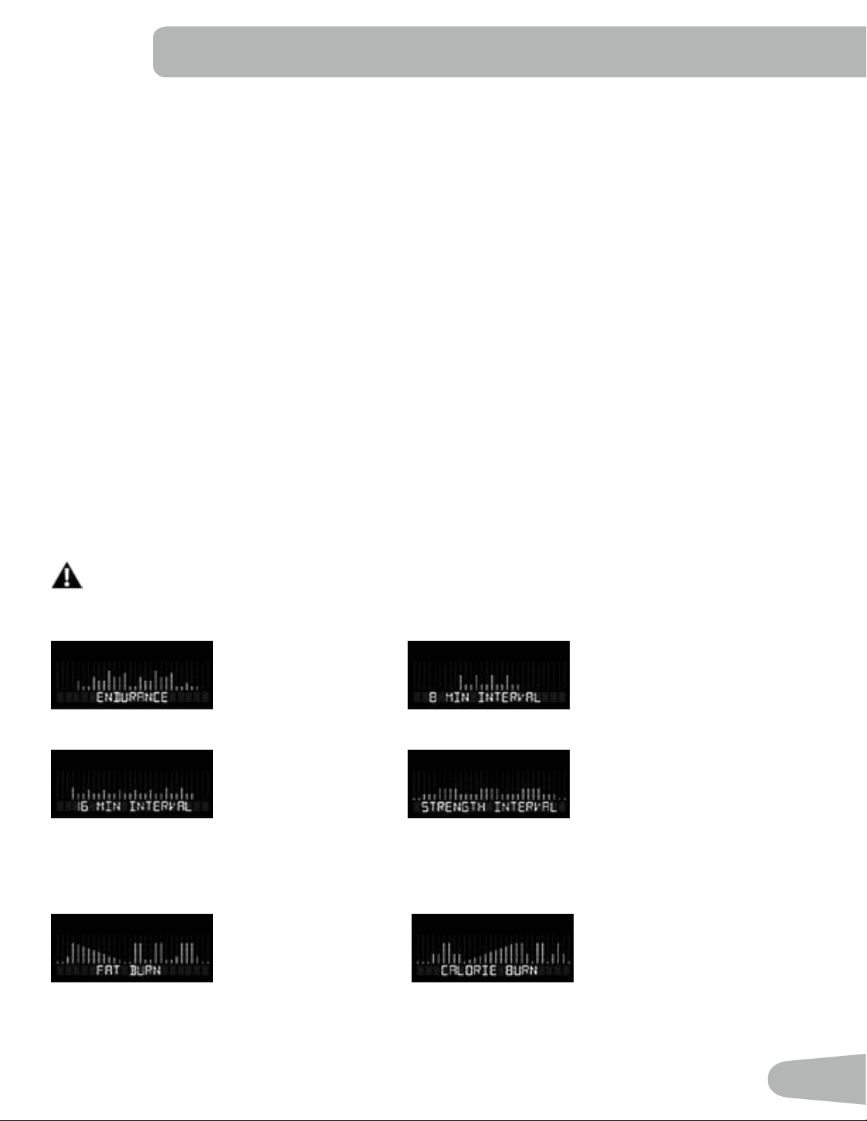
Interval Programs
During the Interval Programs, the workout will switch between an increased intensity, “Sprint” period (more resistance),
and a slower paced, “catch your breath” time period ( “Recover”, or less resistance ). This shift between Sprint and
Recover is repeated over the entire workout. For example, in the 8 Min Interval program the “Sprint” period is 30 seconds,
and the “Recover” period is 90 seconds.
Note: Each “Recover” period is represented by 2 columns on the display.
The “Sprint” period of an Interval Program is a suggested increase in resistance level and speed, and
should only be followed if your physical tness level allows.
Endurance 8 Min Interval
16 Min Interval Strength Interval
Non-Interval Programs
Fat Burn Calorie Burn
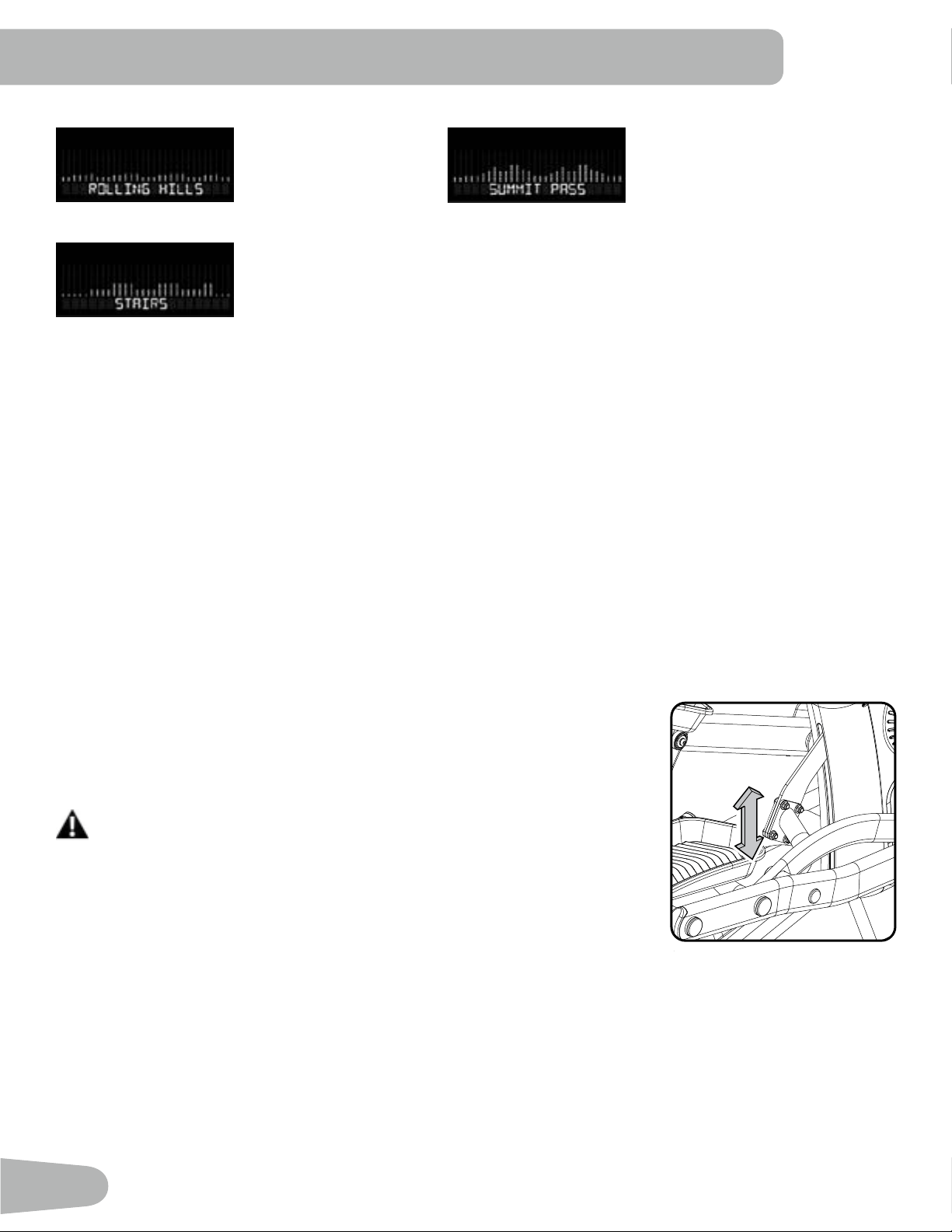
40
Rolling Hills Summit Pass
Stairs
Modify Display of Workout Values
To switch units between kilometers and miles before a workout, push the Programs button and hold for 3 seconds to enter
the Console Setup Mode. The System Units prompt appears. Push an Resistance Increase/Decrease button to change
the units (KM/KG or MI/LB). With the desired unit of measurement displayed, push the Start button to save.
Note: The default system of measurement is MI/LB.
Changing Resistance Levels
Push the Resistance Increase() or Decrease() buttons to change the resistance level at any time in a workout
program. To rapidly change the resistance level, push the desired Resistance Level Quick Button. The Console will adjust
to the selected resistance level of the Quick button.
Changing Incline Levels
Push the Incline Level Increase() or Decrease() buttons to change the incline angle
of the Rail Assembly at any time in a workout program. To rapidly change the incline
level, push the desired Incline Level Quick Button. The Console will adjust to the se-
lected incline level of the quick button.
Be sure the area below the machine is clear before lowering. Fully lower the
incline after each workout.
Exercise on this machine requires coordination and balance. Be sure to an-
ticipate that changes in resistance levels and incline angle of Rail Assembly
can occur during workouts, and be attentive in order to avoid loss of bal-
ance and possible injury.
Be sure that the workout space you are utilizing has adequate height clearance, taking into consideration
the height of the user and the maximum height of the fully inclined Rail Assembly.
Note: The incline (lift) motor may pause adjustments to the incline for a few minutes if it has been used a lot in a short
period of time. The Console will display “Incline Cooling” during the pause.

41
Pausing or Stopping
1. Push the Pause/Stop button or stop pedaling for 5 seconds to pause your workout.
2. To continue your workout, push Start or begin pedaling.
To stop the workout, push the Pause/Stop button. The Console will go into Workout Summary mode. Push PAUSE/
STOP again to exit to the Welcome screen.
Muting the Console
The Console has the option to be muted. To disable the audible cues, tap the Volume button to cycle through the volume
levels: O, 1, 2 (default), 3. It does not aect the output from your personal device.
Note: The Console will reset to the last volume setting for the selected User Profile after each power-up.
Workout Summary Mode
After a workout, the Console display will show “Workout Complete” then “Saving Workout”. The Console will show the
Workout Summary values for 5 minutes. The workout must be longer than 1 minute in order to store the data.
The summary includes total and average workout values. The total workout values are Time, Distance, Calories and
Intervals Completed. The average workout values are Speed, Sprint Burn Rate, Watts, Heart Rate (if available), Cadence,
Incline and Resistance.
Note: If no Heart Rate was provided during the workout, the Console will not report a value.
The Workout Summary will end after 5 minutes or if the Pause/Stop button is pushed.

42
The Console Setup Mode allows you to set units of measurement to either Imperial or metric, adjust screen brightness,
view maintenance statistics (such as Run Time hours and software version – for service technician use only), or reset the
Console.
1. Push the Programs button and hold for 3 seconds while in the Power-Up Mode to go into the Console Setup Mode
(System Menu).
Note: Push the Pause/Stop button to exit the System Menu and return to the Power-Up Mode screen.
2. The Console display shows the System Units prompt with the current setting. The default setting is Imperial English
units. Push the Resistance Increase/Decrease buttons to change between Imperial (MI/LB) and metric (KM/KG).
Note: If the units change when there is data in User Statistics, the statistics convert to the new units.
3. Push the Programs button to set the selection and continue to the next menu option.
Note: To save the selection and exit the System Menu, push the Start button. To exit without saving, push the Pause/
Stop button.
4. The Console display shows the Screen Brightness prompt with the current setting. The 5 levels of brightness are: 5
(100%), 4 (default, 95%), 3 (90%), 2 (85%), 1 (80%). The display shows the brightness of the selected level. Push the
Resistance Increase/Decrease buttons to move to the desired level.
5. Push the Programs button to set the selection and continue to the next menu option.
6. The Console display shows the Disconnect Bluetooth prompt. The default option is NO. The YES option will discon-
nect all Bluetooth
®
devices. Push the Resistance Increase/Decrease buttons to change between options (YES/NO).
7. Push the Programs button to set the selection and continue to the next menu option.
8. The Console display shows the Auto Connect HR (Heart Rate) prompt. The default option is YES. Push the Resis-
tance Increase/Decrease buttons to change between options (YES/NO).
9. Push the Programs button to set the selection and continue to the next menu option.
10. The Console display shows the Hardware Variant & Console Firmware Version.
11. Push the Programs button to continue to the next menu option.
12. The Console display shows the Base Serial Number.
13. Push the Programs button to continue to the next menu option.
14. The Console display shows the Hardware Variant (machine type).
15. Push the Programs button to set the selection and continue to the next menu option.
16. The Console display shows the Run Time hours (total number of hours of workout time).
17. Push the Programs button to continue to the next menu option.
18. The Console display shows the BLE Version.
19. Push the Programs button to continue to the next menu option.
20. The Console display shows the BTC Version.
21. Push the Programs button to continue to the next menu option.
22. The Console display shows the SENSOR Version.
23. Push the Programs button to continue to the next menu option.
24. The Console display shows the Error Log prompt (for service technician use only). Push the Resistance Decrease
button to move through the logged errors. At the end of the logged errors, the Console display shows the Clear Errors
prompt (for service technician use only). To clear the errors, push the Start button.
25. Push the Programs button to continue to the next menu option.
26. The Console display shows the Reset Console prompt. The default option is NO. Push the Pause/Stop button to exit
CONSOLE SETUP MODE

43
without starting Reset.
Note: The YES option will reset the System Units, Screen Brightness and Demo Mode to default settings. It does not
reset the Run Time Hours.
Push the Resistance Increase/Decrease buttons to change between options (YES/NO).
Push the Start button to set the selection and exit the System Menu.
27. The Console will display the Power-Up Mode screen.

44
Read all maintenance instructions fully before you start any repair work. In some conditions, an assistant is required to do
the necessary tasks.
Equipment must be regularly examined for damage and repairs. The owner is responsible to make sure that
regular maintenance is done. Worn or damaged components must be repaired or replaced immediately.
Only manufacturer supplied components can be used to maintain and repair the equipment.
If at any time the Warning labels become loose, unreadable or dislodged, replace the labels. If purchased
in US/Canada, contact Customer Service for replacement labels. If purchased outside US/Canada, contact
your local distributor for them.
To reduce the risk of electrical shock or unsupervised usage of the equipment, always
unplug the power cord from the wall outlet and/or the machine and wait 5 minutes
before cleaning, maintaining or repairing the machine. Place the power cord in a
secure location.
Daily: Before each use, examine the exercise machine for loose, broken, damaged, or worn parts. Do not use if
found in this condition. Repair or replace all parts at the rst sign of wear or damage. After each workout, use
a damp cloth to wipe your machine and Console free of moisture.
Note: Avoid excessive moisture on the Console.
Weekly: Check for smooth roller operation. Wipe the machine to remove dust, dirt, or grime. Clean the rails and
surface of the rollers with a damp cloth.
Apply silicone lubricant to a dry cloth and wipe the rails to eliminate roller noise.
Silicone lubricant is not intended for human consumption. Keep out of reach of children. Store
in a safe place.
Note: Do not use petroleum based products.
Monthly or after 20 hours: Make sure all bolts and screws are tight. Tighten if necessary.
NOTICE: If necessary, only use a mild dish soap with a soft cloth to clean the Console. Do not clean with a
petroleum based solvent, automotive cleaner, or any product that contains ammonia. Do not clean the
Console in direct sunlight or at high temperatures Be sure to keep the Console free of moisture.
When the machine is used in a Studio/Institutional environment, we recommend that the Pedals be replaced
every year to maintain maximum user safety and performance. Only use replacement Pedals available from
Nautilus. Other brands of Pedals may not be designed for this product, and can cause danger to users and
bystanders, and will void the warranty.
MAINTENANCE
45
Maintenance Parts
Console Assembly
Upper Handlebar, Right
Leg, Right
Leg, Left
Rail Assembly
Pedal, Right
Pedal, Left
Upper Handlebar, Left
Console Pivot Cover
Console Mast
Main Assembly
Handlebar Cover,
Exterior
Handlebar
Cover, Exterior
Handlebar
Cover, Interior
Handlebar
Cover, Interior
Power Cord
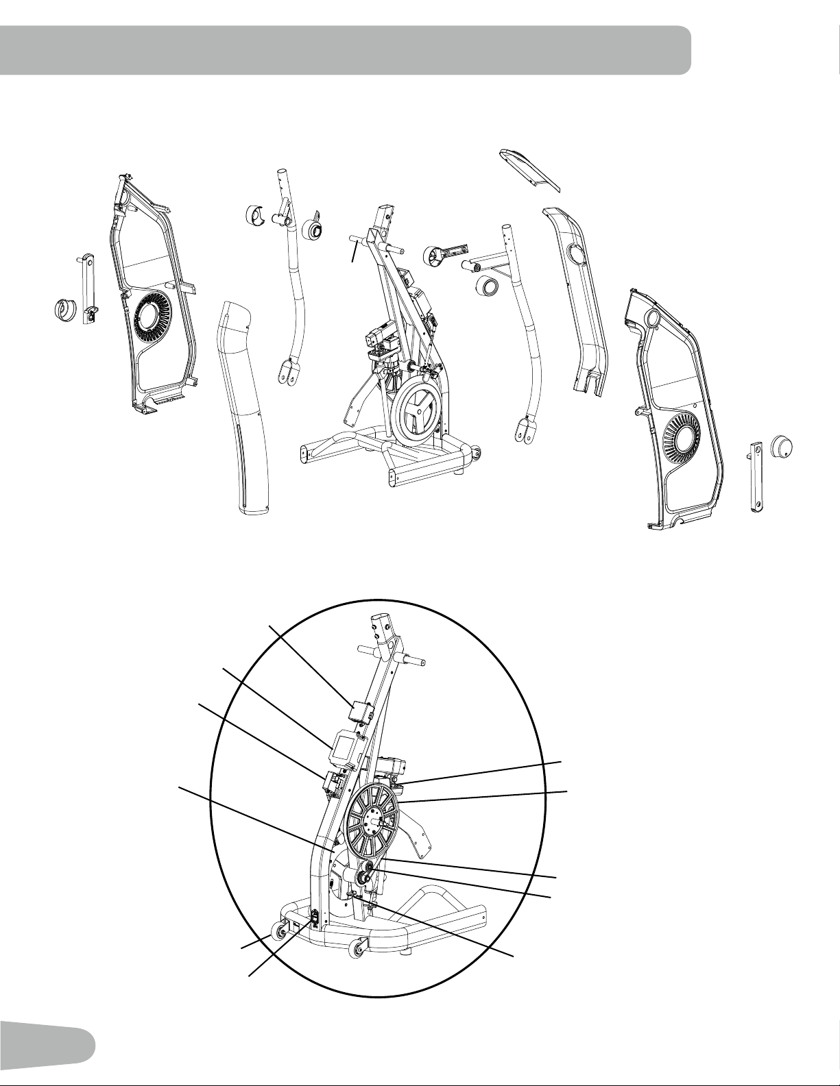
46
Lower Handle-
bar, Right
Main Assembly
Front Upper
Shroud
Crank
Cap
Shroud
Front Lower
Shroud
Lower Handle-
bar, Left
Crank
Cap
Shroud
Crank
Arm
Crank
Arm
Left Main Shroud
Right Main Shroud
Pivot Cover
Outer Cap
Inner Pivot
Shroud
Inner Pivot
Shroud
Pivot Cover
Outer Cap
Rear Shroud
Servo Motor
Transport Wheel
Power Switch and Inlet
Flywheel
Speed Sensor Assembly
Incline (Lift) Motor
Drive Pulley
Drive Belt
Idler Pulley
Sensor Board
Oine Power Supply
Main Assembly Frame
Pivot Rod

47
TROUBLESHOOTING
Condition/Problem Things to Check Solution
No display/partial display/
unit will not turn on
Check electrical (wall)
outlet
Make sure unit is plugged into a functioning wall outlet.
Check connection at front
of unit
Connection should be secure and undamaged. Replace cord
or power inlet if either are damaged.
Check data cable integrity All wires in cable should be intact. If any are visibly pinched or
cut, replace cable.
Check data cable
connections/orientation
Be sure cables at base of mast and at back of console are con-
nected securely and oriented properly. Small latch on connec-
tor should line up and snap into place.
Check console display for
damage
Check for visual sign that console display is cracked or other-
wise damaged. Replace Console if damaged.
Console Display If Console only has partial display and all connections are ne,
replace the Console.
Console display shows "0
Base Hub Comm Error"
error code
Check data cable integrity All wires in cable should be intact. If any are visibly pinched or
cut, replace cable.
Check data cable
connections/orientation
Be sure cables at base of mast and at back of console are con-
nected securely and oriented properly. Small latch on connec-
tor should line up and snap into place.
Check console display for
damage
Check for visual sign that console display is cracked or other-
wise damaged. Replace Console if damaged.
If the above steps do not resolve the problem, contact Cus-
tomer Service (if inside US/Canada) or your local distributor (if
outside US/Canada).
Console display shows "3
Stuck Button Error" error
code
Check console keypad Check for stuck buttons on the Console keypad. Replace Con-
sole if damaged.
Be sure there is no object resting on one of the buttons de-
pressing it. if issue persists, replace console.
Console display shows "5
NVRAM Error" error code
Console Indicates problem with ash memory on Console. Contact Cus-
tomer Service (if inside US/Canada) or your local distributor (if
outside US/Canada).
Unit operates but
Bluetooth
®
Heart Rate
(HR) not displayed
HR monitor (not provided) Follow the troubleshooting instructions provided with the
device.
HR monitor batteries If monitor has replaceable batteries, install new batteries.
Interference Try moving unit away from sources of interference (TV, Micro-
wave, etc).
On/O LED button During a workout, only push the On/O LED button once to
activate the armband.
Replace HR device If interference is eliminated and HR does not function, replace
HR device.
If the above steps do not resolve the problem, contact Cus-
tomer Service (if inside US/Canada) or your local distributor (if
outside US/Canada).

48
Condition/Problem Things to Check Solution
No speed/RPM reading Check data cable integrity All wires in cable should be intact. If any are cut or pinched,
replace cable.
Check data cable
connections/orientation
Be sure each cable is connected securely and oriented proper-
ly. Small latch on connector should line up and snap into place.
Check magnet position
(requires shroud removal)
Magnet should be in place on pulley.
Check Speed Sensor
(requires shroud removal)
Speed sensor should be aligned with magnet and connected to
data cable. Realign sensor if necessary. Replace if there is any
damage to the sensor or the connecting wire.
Resistance does not
change (machine turns on
and operates)
Check data cable integrity All wires in cable should be intact. If any are visibly pinched or
cut, replace cable.
Check data cable
connections/orientation
Be sure cable is connected securely and oriented properly.
Small latch on connector should line up and snap into place.
Check Servo Motor
(requires shroud removal)
Replace Servo Motor if not functioning properly.
Check Console display for
damage
Check for visual sign that console display is cracked or other-
wise damaged. Replace Console if damaged.
Resistance handlebar
connection
Be sure cable from right Upper Handlebar and cables to Con-
sole are secure and undamaged.
If the above steps do not resolve the problem, contact Cus-
tomer Service (if inside US/Canada) or your local distributor (if
outside US/Canada).
Incline does not adjust
(machine turns on and
operates)
Check data cable
connections/orientation
Be sure cable is connected securely and oriented properly.
Small latch on connector should line up and snap into place.
Check Console display for
damage
Check for visual sign that console display is cracked or other-
wise damaged. Replace Console if damaged.
Incline handlebar
connection
Be sure cable from left Upper Handlebar and cables to Console
are secure and undamaged.
Incline Adjuster Assembly
(requires shroud removal)
Be sure Incline Adjuster Assembly is attached to Incline Motor
drive screw.
Console display shows
“Incline Cooling” error
code
Additional incline adjustments are disabled for a few minutes to
protect the motor from over heating. Allow the lift motor to cool,
and then resume your workout.
If the above steps do not resolve the problem, contact Cus-
tomer Service (if inside US/Canada) or your local distributor (if
outside US/Canada).

49
Condition/Problem Things to Check Solution
Console shuts o (enters
sleep mode) while in use
Check electrical (wall)
outlet
Make sure unit is plugged into a functioning wall outlet.
Check connection at front
of unit
Connection should be secure and undamaged. Replace cord
or power inlet if either are damaged.
Check data cable integrity All wires in the cable should be intact. If any are cut or pinched,
replace cable.
Check data cable
connections/orientation
Be sure cable is connected securely and oriented properly.
Small latch on connector should line up and snap into place.
Reset machine Unplug unit from electrical outlet for 3 minutes. Reconnect to
outlet.
Check magnet position
(requires shroud removal)
Magnet should be in place on pulley.
Check Speed Sensor
(requires shroud removal)
Speed sensor should be aligned with magnet and connected to
data cable. Realign sensor if necessary. Replace if there is any
damage to the sensor or the connecting wire.
Unit rocks/does not sit
level
Check leveler adjustment Adjust levelers until machine is level.
Check surface under unit Adjustment may not be able to compensate for extremely un-
even surfaces. Move machine to level area.
Pedals loose/unit dicult
to operate
Hardware Tightly secure all hardware on the Pedals, Legs and Handlebar
Arms.
Drive train click/tick
noise once per full crank
revolution
Check crank/pulley
assembly
Disconnect left and right foot assemblies and rotate crank. If
sound persists, replace crank/pulley assembly. If sound does
not come from rotating crank, check foot assemblies and up-
per/lower handlebars.
Check Pedal, Leg and
Handlebar assemblies
Manually move Pedal, Leg, and Handlebar assemblies to iso-
late sound. Replace part making sound.
Check for loose hardware Tightly secure all hardware on the Rail Assembly and the base
of the Console Mast.
Knocking sound during
machine operation
Check hardware at
junction between Lower
Handlebar Arm and Pedal
Make sure that the alignment tab on the Pivot Sleeve goes into
the slot in the hole. Be sure the Pivot Sleeve extends through
the opposite hole in the joint cover.
Squeaking noise
that appears a few
minutes into a workout
and normally will get
progressively worse as
the workout continues
Bolts that connect the
Lower Handlebars to the
axle running through the
Main Assembly
Loosen pivot rod bolts slightly until noise goes away. White
lithium grease can also be applied for a temporary x. Contact
Customer Service (if inside US/Canada) or your local distribu-
tor (if outside US/Canada).
Roller squeaking on rail Apply silicone lubricant to a dry cloth and wipe the rails to
eliminate roller noise.
Console continuously
cycles through program
screens
Console is in demonstra-
tion mode
Press and hold the Schwinn
™
logo button for 3 seconds. The
setting will take eect after the next time the machine goes into
Sleep Mode.

50

51

8030981.081523.C
™
EN