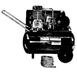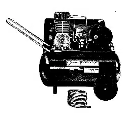
Operators Manual
Permanently Lubricated
Tank Mounted
AIR COMPRESSOR
Model No.
919.152120
• Safety Guidelines
• Assembly
• Operation
• Maintenance
• Service and Adjustments
• Troubleshooting
• Espa_ol
CAUTION: Read the Safety Guidelines
and All Instructions Carefully Before
Operating.
Sears, Roebuck and Co., Hoffman Estates, IL 60170 U.S.A.
Visit our Craftsman website: www.sears.com/craftsman
D21850 Rev. 0 10/18/00
WARRANTY ............................. 2
SAFETY GUIDELINES .................... 3-6
GLOSSARY .............................. 7
ACCESSORIES .......................... 7
ASSEMBLY .............................. 7
Contents of Carton ...................... 7
Assembly ............................. 7
INSTALLATION ........................... 8
Location of Air Compressor ............... 8
Grounding Instructions ................... 8
Extension Cords ........................ 8
Voltage and Circuit Protection ............. 8
OPERATION ........................... 9-10
Know Your Air Compressor ............... 9
Description of Operation ................. 9
How to Stop .......................... 10
Before Starting ........................ 10
Before Each Start-Up ................... 10
How to Start .......................... 10
MAINTENANCE .......................... 11
Customer Responsibilities ............... 11
To Check Safety Valve .................. 11
To Drain Tank ......................... 11
SERVICE AND ADJUSTMENTS ............. 12
To Replace or Clean Check Valve .......... 12
To Replace Regulator ................... 12
STORAGE .............................. 13
TROUBLESHOOTING GUIDE ............ f4-15
ESPAI_IOL ............................ 16-29
HOW TO ORDER REPAIR PARTS ..... Back Cover
FULL ONE YEAR WARRANTY
AIR COMPRESSOR
If this air compressor fails due to a defect in material or workmanship within one year from the date of
purchase, RETURN IT TO THE NEAREST SEARS REPAIR CENTER THROUGHOUT THE UNITED STATES
AND SEARS WILL REPAIR IT, FREE OF CHARGE, If purchased from Orchard Supply Hardware, return to
the nearest Orchard Store and Orchard will repair it, free of charge.
If this air compressor is used for commercial or rental purposes, the warranty will apply for ninety days
from the date of purchase.
This warranty gives you specific legal rights and you may have other rights which vary from state to state.
Sears, Robebuck and Co., Deptr. 817WA, Hoffman Estates, II 60170
D21850 2- ENG
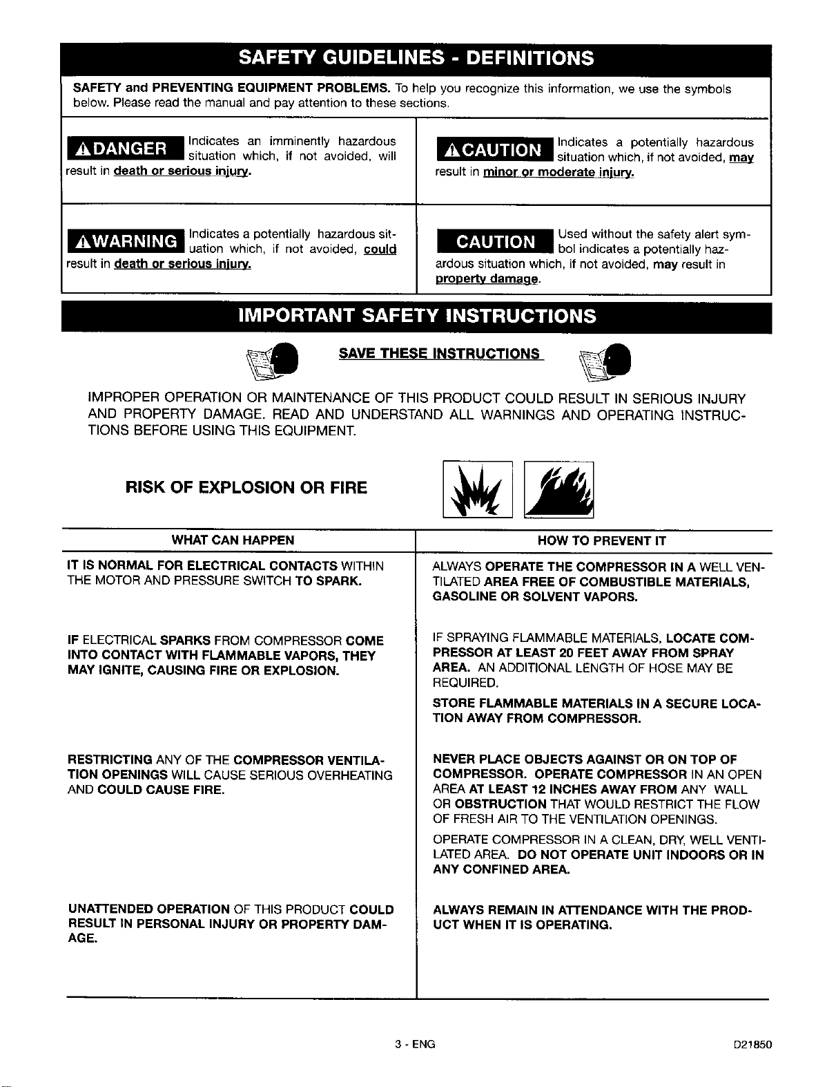
SAFETY and PREVENTING EQUIPMENT PROBLEMS. To help you recognize this information, we use the symbols
below. Please read the manual and pay attention to these sections.
Indicates an imminently hazardous
which, if not avoided, will
result in death or serious injury.
Indicates a potentially hazardous sit-
which, if not avoided, could
result in death or serious iniury.
Indicates a potentially hazardous
if not avoided,
result in minor or moderate injury.
Used without the safety alert sym-
a potentially haz-
ardous situation which, if not avoided, may result in
orooertv damage.
SAVE THESE INSTRUCTIONS
IMPROPER OPERATION OR MAINTENANCE OF THIS PRODUCT COULD RESULT IN SERIOUS INJURY
AND PROPERTY DAMAGE. READ AND UNDERSTAND ALL WARNINGS AND OPERATING INSTRUC-
TIONS BEFORE USING THIS EQUIPMENT.
RISK OF EXPLOSION OR FIRE
WHAT CAN HAPPEN
IT IS NORMAL FOR ELECTRICAL CONTACTS WITHIN
THE MOTOR AND PRESSURE SWITCH TO SPARK.
IF ELECTRICAL SPARKS FROM COMPRESSOR COME
INTO CONTACT WITH FLAMMABLE VAPORS, THEY
MAY IGNITE, CAUSING FIRE OR EXPLOSION.
RESTRICTING ANY OF THE COMPRESSOR VENTILA-
TION OPENINGS WILL CAUSE SERIOUS OVERHEATING
AND COULD CAUSE FIRE.
UNATTENDED OPERATION OF THIS PRODUCT COULD
RESULT IN PERSONAL INJURY OR PROPERTY DAM-
AGE.
HOW TO PREVENT IT
ALWAYS OPERATE THE COMPRESSOR IN A WELL VEN-
TILATED AREA FREE OF COMBUSTIBLE MATERIALS,
GASOLINE OR SOLVENT VAPORS,
IF SPRAYING FLAMMABLE MATERIALS, LOCATE COM-
PRESSOR AT LEAST 20 FEET AWAY FROM SPRAY
AREA. AN ADDITIONAL LENGTH OF HOSE MAY BE
REQUIRED.
STORE FLAMMABLE MATERIALS IN A SECURE LOCA-
TION AWAY FROM COMPRESSOR.
NEVER PLACE OBJECTS AGAINST OR ON TOP OF
COMPRESSOR. OPERATE COMPRESSOR IN AN OPEN
AREA AT LEAST 12 INCHES AWAY FROM ANY WALL
OR OBSTRUCTION THAT WOULD RESTRICT THE FLOW
OF FRESH AIR TO THE VENTILATION OPENINGS.
OPERATE COMPRESSOR IN A CLEAN, DRY, WELL VENTI-
LATED AREA. DO NOT OPERATE UNIT INDOORS OR IN
ANY CONFINED AREA.
ALWAYS REMAIN IN ATTENDANCE WITH THE PROD-
UCT WHEN IT IS OPERATING.
3-ENG D21850
RISK OF BURSTING
AIR TANK: THE FOLLOWING CONDITIONS COULD LEAD TO A WEAKENING OF THE TANK, AND
RESULT IN A VIOLENT TANK EXPLOSION AND COULD CAUSE PROPERTY DAMAGE OR SERIOUS
INJURY.
WHAT CAN HAPPEN HOW TO PREVENT IT
1. FAILURE TO PROPERLY DRAIN CONDENSED
WATER FROM THE TANK, CAUSING RUST
AND THINNING OF THE STEEL TANK.
2. MODIFICATIONS OR ATTEMPTED REPAIRS TO THE
TANK.
3. UNAUTHORIZED MODIFICATIONS TO THE
UNLOADER VALVE, SAFETY VALVE, OR ANY
OTHER COMPONENTS WHICH CONTROL TANK
PRESSURE.
4. EXCESSIVE VIBRATION CAN WEAKEN THE AIR
TANK AND CAUSE RUPTURE OR EXPLOSION.
ATTACHMENTS & ACCESSORIES:
EXCEEDING THE PRESSURE RATING OF AIR TOOLS,
SPRAY GUNS, AIR OPERATED ACCESSORIES, TIRES AND
OTHER INFLATABLES CAN CAUSE THEM TO EXPLODE
OR FLY APART, AND COULD RESULT IN SERIOUS INJURY.
DRAIN TANK DALLY OR AFTER EACH USE. IF TANK
DEVELOPS A LEAK, REPLACE IT IMMEDIATELY WITH A
NEW TANK OR REPLACE THE ENTIRE COMPRESSOR.
NEVER DRILL INTO, WELD, OR MAKE ANY MODIFICA-
TIONS TO THE TANK OR ITS AI-£ACHMENTS.
THE TANK IS DESIGNED TO WITHSTAND SPECIFIC OPER-
ATING PRESSURES. NEVER MAKE ADJUSTMENTS OR
PARTS SUBSTITUTIONS TO ALTER THE FACTORY SET
OPERATING PRESSURES.
FOR ESSENTIAL CONTROL OF AIR PRESSURE,YOU
MUST INSTALL A PRESSURE REGULATOR AND PRES-
SURE GAUGE TO THE AIR OUTLET (IF NOT EQUIPPED)
OF YOUR COMPRESSOR. FOLLOW THE EQUIPMENT
MANUFACTURERS RECOMMENDATION AND NEVER
EXCEED THE MAXIMUM ALLOWABLE PRESSURE RATING
OF ATTACHMENTS. NEVER USE COMPRESSOR TO
INFLATE SMALL LOW-PRESSURE OBJECTS SUCH AS
CHILDREN'S TOYS, FOOTBALLS, BASKETBALLS, ETC.
RISK FROM FLYING OBJECTS
WHAT CAN HAPPEN
THE COMPRESSED AIR STREAM CAN CAUSE SOFT TIS-
SUE DAMAGE TO EXPOSED SKIN AND CAN PROPEL
DIRT, CHIPS, LOOSE PARTICLES AND SMALL OBJECTS
AT HIGH SPEED, RESULTING IN PROPERTY DAMAGE OR
PERSONAL INJURY.
HOW TO PREVENTIT
ALWAYS WEAR ANSI Z87.t APPROVED SAFETY GLASS-
ES WITH SIDE SHIELDS WHEN USING THE COMPRES-
SOR.
NEVER POINT ANY NOZZLE OR SPRAYER TOWARD
ANY PART OF THE BODY OR AT OTHER PEOPLE OR
ANIMALS.
ALWAYS TURN THE COMPRESSOR OFF AND BLEED
PRESSURE FROM THE AIR HOSE AND TANK BEFORE
All'EMPTING MAINTENANCE, ATFACHING TOOLS OR
ACCESSORIES.
D21850 4 - ENG
RISK OF ELECTRICAL SHOCK
WHAT CAN HAPPEN
YOUR AIR COMPRESSOR IS POWERED BY ELECTRICI-
TY. LIKE ANY OTHER ELECTRICALLY POWERED DEVICE,
IF IT IS NOT USED PROPERLY IT MAY CAUSE ELECTRIC
SHOCK.
REPAIRS ATTEMPTED BY UNQUALIFIED PERSONNEL
CAN RESULT IN SERIOUS INJURY OR DEATH BY ELEC-
TROCUTION,
ELECTRICAL GROUNDING: FAILURE TO PROVIDE ADE-
QUATE GROUNDING TO THIS PRODUCT COULD
RESULT IN SERIOUS INJURY OR DEATH FROM ELEC-
TROCUTION. SEE GROUNDING INSTRUCTIONS.
HOW TO PREVENT IT
NEVER OPERATE THE COMPRESSOR OUTDOORS WHEN
IT IS RAINING OR IN WET CONDITIONS.
NEVER OPERATE COMPRESSOR WITH PROTECTIV-
COVERS REMOVED OR DAMAGED.
ANY ELECTRICAL WIRING OR REPAIRS REQUIRED ON
THIS PRODUCT SHOULD BE PERFORMED BY AUTHO-
RIZED SERVICE CENTER PERSONNEL IN ACCORDANCE
WITH NATIONAL AND LOCAL ELECTRICAL CODES.
MAKE CERTAIN THAT THE ELECTRICAL CIRCUIT TO
WHICH THE COMPRESSOR IS CONNECTED PROVIDES
PROPER ELECTRICAL GROUNDING, CORRECT VOLT-
AGE AND ADEQUATE FUSE PROTECTION.
RISK TO BREATHING
WHAT CAN HAPPEN HOW TO PREVENT IT
THE COMPRESSED AIR DIRECTLY FROM YOUR COM-
PRESSOR IS NOT SAFE FOR BREATHING. THE AIR
STREAM MAY CONTAIN CARBON MONOXIDE, TOXIC
VAPORS, OR SOLID PARTICLES FROM THE TANK.
BREATHING THESE CONTAMINANTS CAN CAUSE
SERIOUS INJURY OR DEATH.
SPRAYED MATERIALS SUCH AS PAINT, PAINT SOL-
VENTS, PAINT REMOVER, INSECTICIDES, WEED
KILLERS, CONTAIN HARMFUL VAPORS AND POISONS.
AIR OBTAINED DIRECTLY FROM THE COMPRESSOR
SHOULD NEVER BE USED TO SUPPLY AIR FOR HUMAN
CONSUMPTION. IN ORDER TO USE AIR PRODUCED BY
THIS COMPRESSOR FOR BREATHING, SUITABLE FIL-
TERS AND IN-LINE SAFETY EQUIPMENT MUST BE
PROPERLY INSTALLED. IN-LINE FILTERS AND SAFETY
EQUIPMENT USED IN CONJUNCTION WITH THE COM-
PRESSOR MUST BE CAPABLE OF TREATING AIR TO ALL
APPLICABLE LOCAL AND FEDERAL CODES PRIOR TO
HUMAN CONSUMPTION.
WORK IN AN AREA WITH GOOD CROSS-VENTILATION.
READ AND FOLLOW THE SAFETY INSTRUCTIONS PRO-
VIDED ON THE LABEL OR SAFETY DATA SHEETS FOR
THE MATERIAL YOU ARE SPRAYING, USE A
NIOSH/MSHA APPROVED RESPIRATOR DESIGNED FOR
USE WITH YOUR SPECIFIC APPLICATION.
5 - ENG D21850
RISK OF BURNS
WHAT CAN HAPPEN
TOUCHING EXPOSED METAL SUCH AS THE COMPRES-
SOR HEAD OR OUTLET TUBES, CAN RESULT IN
SERIOUS BURNS.
HOW TO PREVENT IT
NEVER TOUCH ANY EXPOSED METAL PARTS ON
COMPRESSOR DURING OR IMMEDIATELY AFTER OPER-
ATION. COMPRESSOR WILL REMAIN HOT FOR SEVERAL
MINUTES AFTER OPERATION.
DO NOT REACH AROUND PROTECTIVE SHROUDS OR
ATTEMPT MAINTENANCE UNTIL UNIT HAS BEEN
ALLOWED TO COOL.
RISK FROM MOVING PARTS
WHAT CAN HAPPEN HOW TO PREVENT IT
MOVING PARTS SUCH AS THE PULLEY, FLYWHEEL AND
BELT CAN CAUSE SERIOUS INJURY IF THEY COME
INTO CONTACT WITH YOU OR YOUR CLOTHING.
ATTEMPTING TO OPERATE COMPRESSOR WITH DAM-
AGED OR MISSING PARTS OR ATrEMPTING TO REPAIR
COMPRESSOR WITH PROTECTIVE SHROUDS REMOVED
CAN EXPOSE YOU TO MOVING PARTS AND CAN
RESULT IN SERIOUS INJURY.
NEVER OPERATE THE COMPRESSOR WITH GUARDS
OR COVERS WHICH ARE DAMAGED OR REMOVED.
ANY REPAIRS REQUIRED ON THJS PRODUCT SHOULD
BE PERFORMED BY AUTHORIZED SERVICE CENTER
PERSONNEL,
RISK OF FALLING
WHAT CAN HAPPEN HOW TO PREVENT IT
A PORTABLE COMPRESSOR CAN FALL FROM A TABLE, ALWAYS OPERATE COMPRESSOR IN A STABLE
WORKBENCH OR ROOF CAUSING DAMAGE TO THE SECURE POSITION TO PREVENT ACCIDENTAL MOVE-
COMPRESSOR AND COULD RESULT IN SERIOUS MENT OF THE UNIT. NEVER OPERATE COMPRESSOR
INJURY OR DEATH TO THE OPERATOR, ON A ROOF OR OTHER ELEVATED POSITION, USE
ADDITIONAL AIR HOSE TO REACH HIGH LOCATIONS,
RISK OF PROPERTY DAMAGE WHEN TRANSPORTING
COMPRESSOR
(Fire, Inhalation, Damage to Vehicle Surfaces)
For units requiring off in pump or gasoline engines
WHAT CAN HAPPEN HOW TO PREVENT IT
OIL CAN LEAK OR SPILL AND COULD RESULT IN FIRE ALWAYS PLACE COMPRESSOR ON A PROTECTIVE MAT
OR BREATHING HAZARD, SERIOUS INJURY OR DEATH WHEN TRANSPORTING TO PROTECT AGAINST DAMAGE
CAN RESULT. OIL LEAKS WILL DAMAGE CARPET, PAINT TO VEHICLE FROM LEAKS. REMOVE COMPRESSOR
OR OTHER SURFACES IN VEHICLES OR TRAILERS. FROM VEHICLE IMMEDIATELY UPON ARRIVAL AT YOUR
DESTINATION.
D21850 6 - ENG
Become familiar with these terms before operating the
unit.
CFM: Cubic feet per minute.
SCFM: Standard cubic feet per minute; a unit of
measure of air delivery.
PSIG: Pounds per square inch gauge; a unit of meas-
ure of pressure.
Code Certification: Products that bear one or more
of the following marks: UL, CUL, ETL, CETL, have
been evaluated by OSHA certified independent safety
laboratories and meet the applicable Underwriters
Laboratories Standards for Safety.
Cut-In Pressure: While the motor is off, air tank
pressure drops as you continue to use your accesso-
ry. When the tank pressure drops to a certain low
level the motor will restart automatically. The low
pressure at which the motor automatically restarts is
called "cut-in" pressure.
Cut-Out Pressure: When an air compressor is
turned on and begins to run, air pressure in the air
tank begins to build. It builds to a certain high pres-
sure before the motor automatically shuts off - pro-
tecting your air tank from pressure higher than its
capacity. The high pressure at which the motor shuts
off is called "cut-out" pressure.
Branch Circuit: Circuit carrying electricity from elec-
trical panel to outlet.
This unit is capable of powering the following Accessories. The accessories are available through the current
Power and Hand Tool Catalog or full-line Sears stores.
Accessories Specialty Tools
• In LineFilter • Air Brush
• TireAir Chuck • Inflating/BlowGun
• Quick Connector Sets * Grease Gun
(varioussizes) • Caulk Gun
• Air PressureRegulators Carpentry Tools
• Oil Fog Lubricators
• FinishingNailer/ Stapler
• Air Hose:
• Construction Nailer/ Stapler
1/4", 5/16" OR 3/8" I.D.
in various lengths Spray Painting
• Multi-PurposeSpray Gun
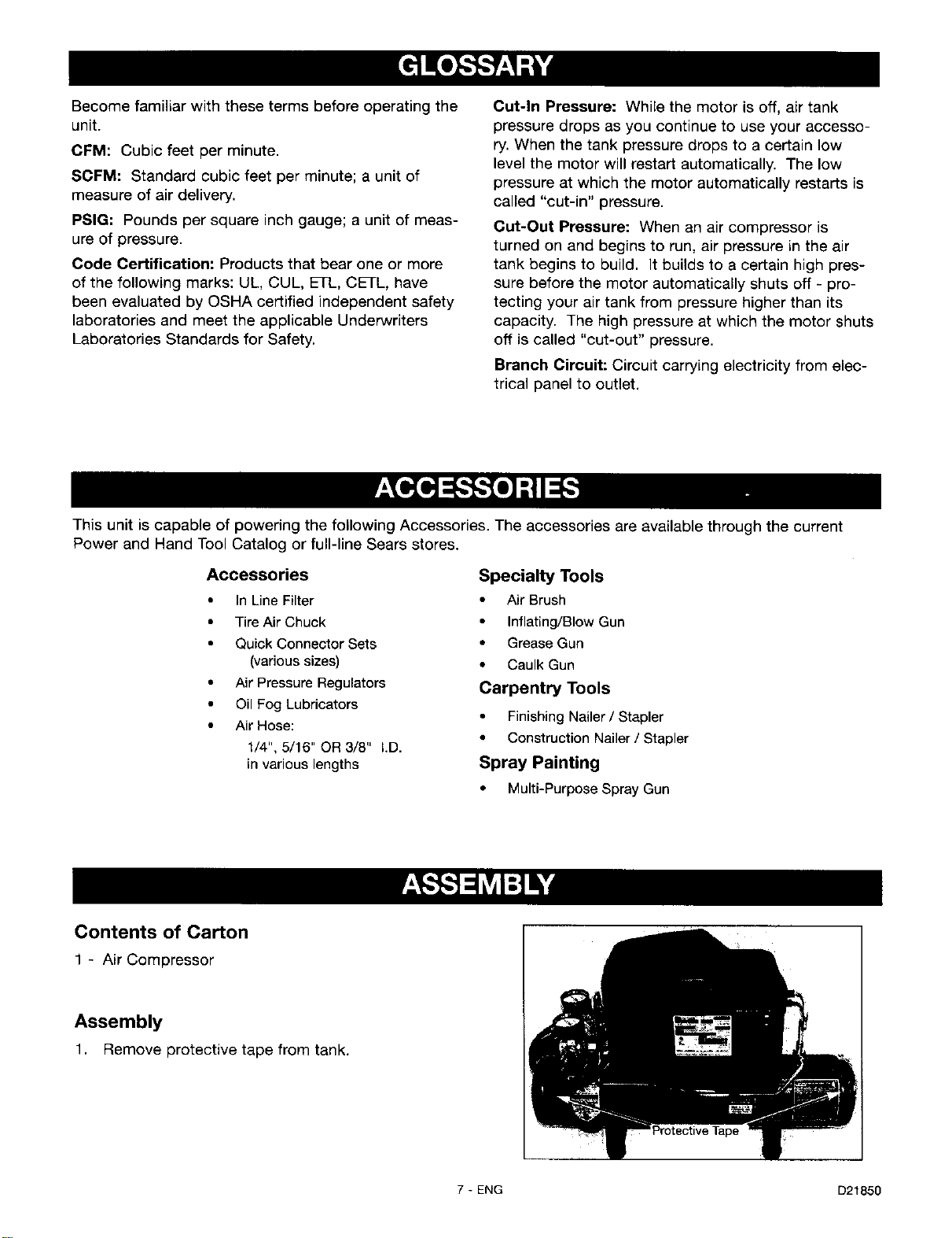
Contents of Carton
1 - Air Compressor
Assembly
1. Remove protective tape from tank.
7-ENG D21850
HOW TO SET UP YOUR UNIT
Location of the Air Compressor
Locate the air compressor in a clean, dry and well
ventilated area. The air compressor should be located
at least 12" away from the wall or other obstructions
that will interfere with the flow of air. The air compres-
sor pump and shroud are designed to allow for proper
cooling. The ventilation openings on the compressor
are necessary to maintain proper operating tempera-
ture. Do not place rags or other containers on or near
these openings.
GROUNDING INSTRUCTIONS
RISK OF ELECTRICAL
SHOCK. In the event of a
short circuit, grounding reduces the risk of
shock by providing an escape wire for the
electric current. This air compressor must be
properly grounded.
The portable air compressor is equipped with a cord
having a grounding wire with an appropriate ground-
ing plug (see following illustrations). The plug must be
used with an outlet that has been installed and
grounded in accordance with all local codes and ordi-
nances.
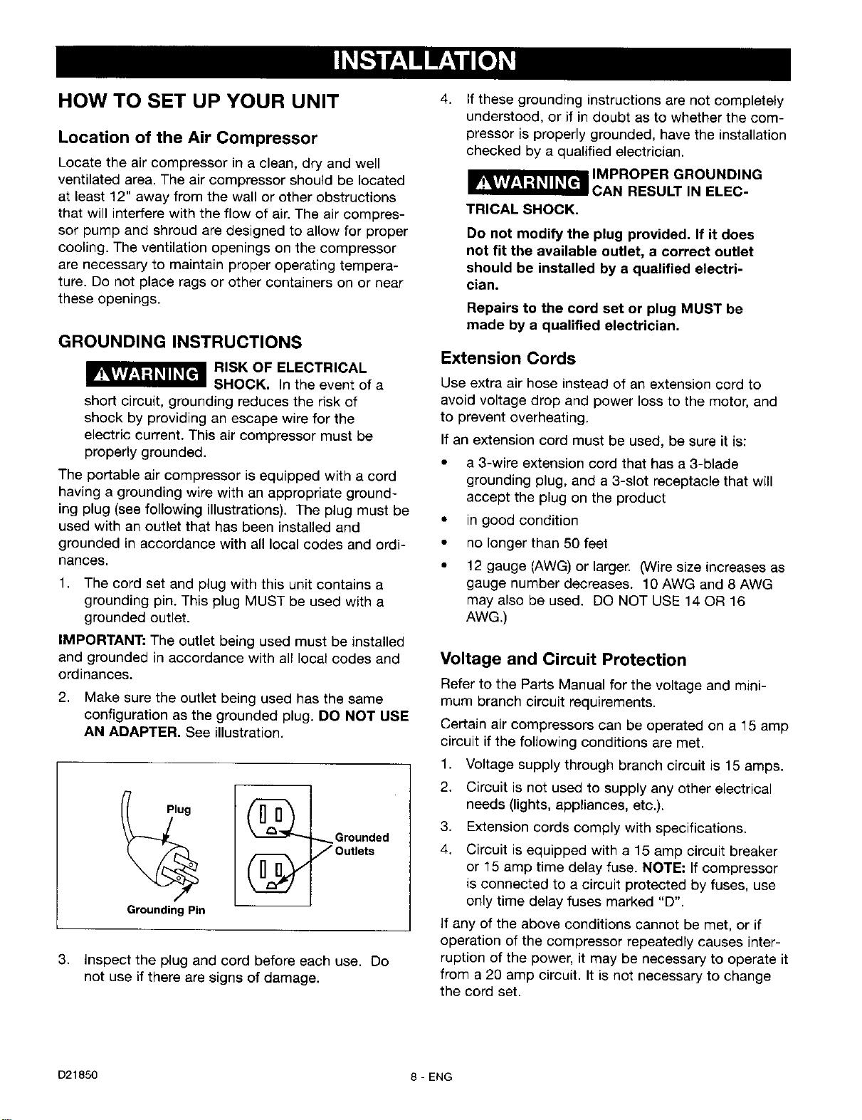
1. The cord set and plug with this unit contains a
grounding pin. This plug MUST be used with a
grounded outlet.
IMPORTANT: The outlet being used must be installed
and grounded in accordance with all local codes and
ordinances.
2. Make sure the outlet being used has the same
configuration as the grounded plug. DO NOT USE
AN ADAPTER. See illustration.
Grounding Pin
Grounded
./Outlets
3. Inspect the plug and cord before each use. Do
not use if there are signs of damage.
4.
If these grounding instructions are not completely
understood, or if in doubt as to whether the com-
pressor is properly grounded, have the installation
checked by a qualified electrician.
IMPROPER GROUNDING
3AN RESULT IN ELEC-
TRICAL SHOCK.
Do not modify the plug provided. If it does
not fit the available outlet, a correct outlet
should be installed by a qualified electri-
cian.
Repairs to the cord set or plug MUST be
made by a qualified electrician.
Extension Cords
Use extra air hose instead of an extension cord to
avoid voltage drop and power loss to the motor, and
to prevent overheating.
If an extension cord must be used, be sure it is:
• a 3-wire extension cord that has a 3-blade
grounding plug, and a 3-slot receptacle that will
accept the plug on the product
• in good condition
• no longer than 50 feet
• 12 gauge (AWG) or larger. (Wire size increases as
gauge number decreases. 10 AWG and 8 AWG
may also be used. DO NOT USE 14 OR 16
AWG .)
Voltage and Circuit Protection
Refer to the Parfs Manual for the voltage and mini-
mum branch circuit requirements.
Certain air compressors can be operated on a 15 amp
circuit if the following conditions are met.
1. Voltage supply through branch circuit is 15 amps.
2. Circuit is not used to supply any other electrical
needs (lights, appliances, etc.).
3. Extension cords comply with specifications.
4.
Circuit is equipped with a 15 amp circuit breaker
or 15 amp time delay fuse. NOTE: If compressor
is connected to a circuit protected by fuses, use
only time delay fuses marked "D".
If any of the above conditions cannot be met, or if
operation of the compressor repeatedly causes inter-
ruption of the power, it may be necessary to operate it
from a 20 amp circuit. It is not necessary to change
the cord set.
D21850 8-ENG
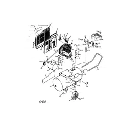
Know Your Air Compressor
READ THIS OWNER'S MANUAL AND SAFETY RULES BEFORE OPERATING YOUR UNIT. Compare the illustra-
tions with your unit to familiarize yourself with the location of various controls and adjustments. Save this manual
for future reference.
Description of Operation
Become familiar with these controls before operating
the unit.
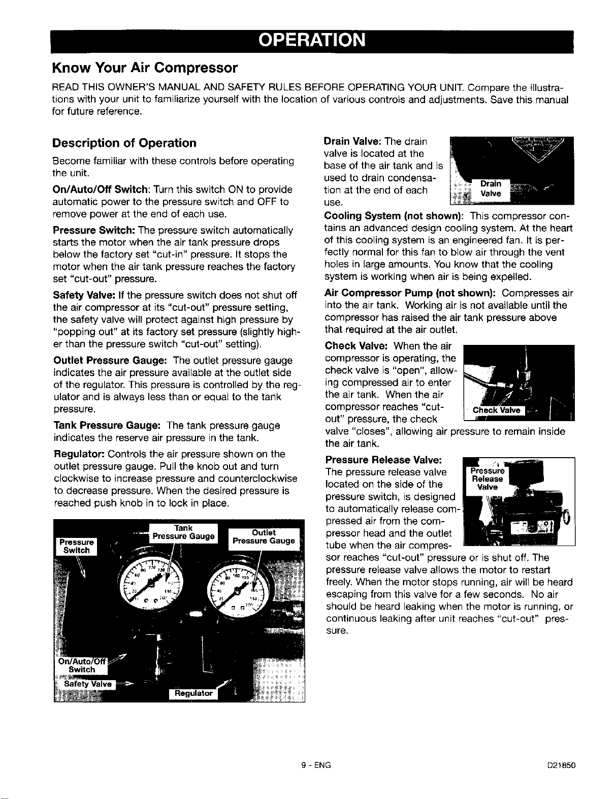
On/Auto/Off Switch: Turn this switch ON to provide
automatic power to the pressure switch and OFF to
remove power at the end of each use.
Pressure Switch: The pressure switch automatically
starts the motor when the air tank pressure drops
below the factory set "cut-in" pressure. It stops the
motor when the air tank pressure reaches the factory
set "cut-out" pressure.
Safety Valve: If the pressure switch does not shut off
the air compressor at its "cut-out" pressure setting,
the safety valve will protect against high pressure by
"popping out" at its factory set pressure (slightly high-
er than the pressure switch "cut-out" setting).
Outlet Pressure Gauge: The outlet pressure gauge
indicates the air pressure available at the outlet side
of the regulator. This pressure is controlled by the reg-
ulator and is always less than or equal to the tank
pressure.
Tank Pressure Gauge: The tank pressure gauge
indicates the reserve air pressure in the tank.
Regulator: Controls the air pressure shown on the
outlet pressure gauge. Pull the knob out and turn
clockwise to increase pressure and counterclockwise
to decrease pressure. When the desired pressure is
reached push knob in to lock in place.
Drain Valve: The drain
valve is located at the
base of the air tank and is
used to drain condensa-
tion at the end of each
use.
Cooling System (not shown): This compressor con-
tains an advanced design cooling system. At the heart
of this cooling system is an engineered fan. It is per-
fectly normal for this fan to blow air through the vent
holes in large amounts. You know that the cooling
system is working when air is being expelled.
Air Compressor Pump (not shown): Compresses air
into the air tank. Working air is not available until the
compressor has raised the air tank pressure above
that required at the air outlet.
Check Valve: When the air
compressor is operating, the
check valve is "open", allow-
ing compressed air to enter
the air tank. When the air
compressor reaches "cut- CheckValve
out" pressure, the check
valve "closes", allowing air pressure to remain inside
the air tank.
Pressure Release Valve:
The pressure release valve
located on the side of the
pressure switch, is designed
to automatically release com-
pressed air from the com-
pressor head and the outlet
tube when the air compres-
sor reaches "cut-out" pressure or is shut off. The
pressure release valve allows the motor to restart
freely. When the motor stops running, air will be heard
escaping from this valve for a few seconds. No air
should be heard leaking when the motor is running, or
continuous leaking after unit reaches "cut-out" pres-
sure.
9-ENG D21850
How to Use Your Unit
How to Stop:
1. Set the On/Auto/Off lever to "OFF".
Before Starting
Break-in Procedure
Serious damage may result ifthe
following break-in instructions are
not closely followed.
This procedure is required before the air compressor
is put into service and when the check valve or a
complete compressor pump has been replaced.
1. Make sure the On/Auto/Off lever is in the "OFF"
position.
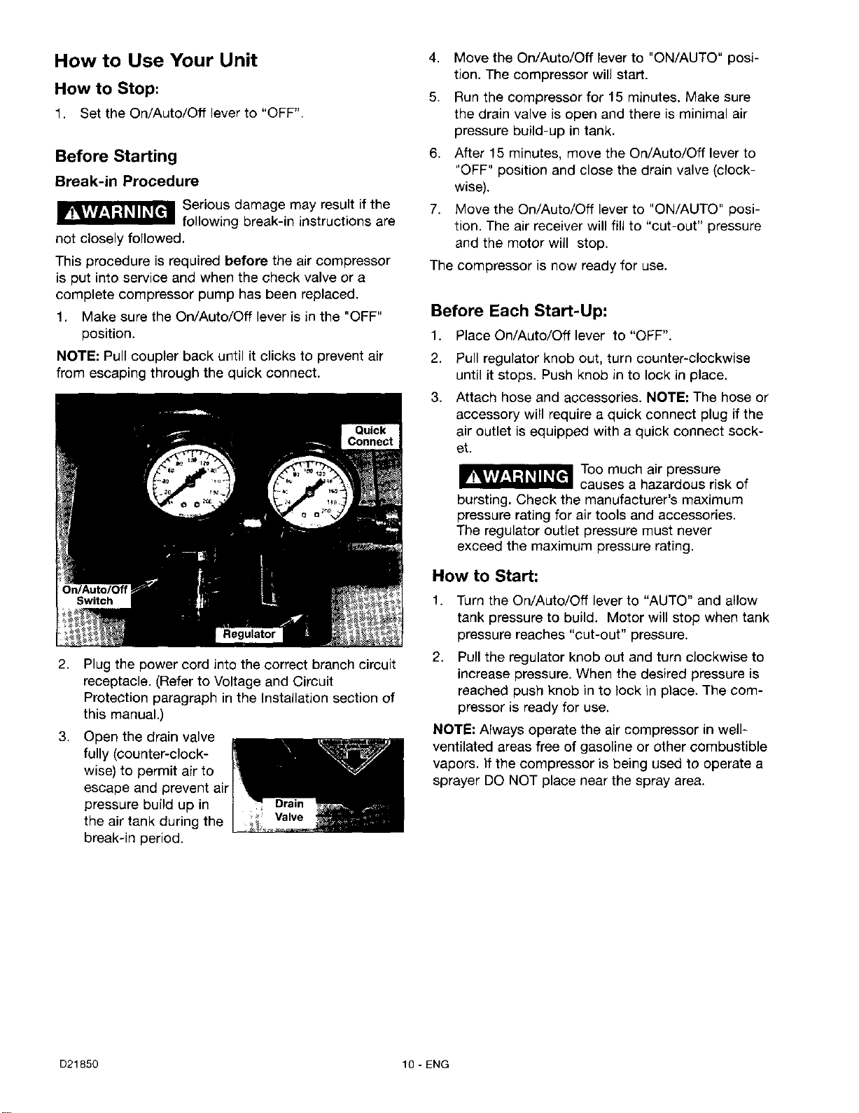
NOTE: Pull coupler back until it clicks to prevent air
from escaping through the quick connect.
2.
Plug the power cord into the correct branch circuit
receptacle. (Refer to Voltage and Circuit
Protection paragraph in the Installation section of
this manual.)
3. Open the drain valve
fully (counter-clock-
wise) to permit air to
escape and prevent air
pressure build up in
the air tank during the
break-in period.
Valve
4. Move the On/Auto/Off lever to "ON/AUTO" posi-
tion. The compressor will start.
5. Run the compressor for 15 minutes. Make sure
the drain valve is open and there is minimal air
pressure build-up in tank.
6. After 15 minutes, move the On/Auto/Off lever to
"OFF" position and close the drain valve (clock-
wise).
7. Move the On/Auto/Off lever to "ON/AUTO" posi-
tion. The air receiver will fill to "cut-out" pressure
and the motor will stop.
The compressor is now ready for use.
Before Each Start-Up:
1. Place On/Auto/Off lever to "OFF".
2,
3.
Pull regulator knob out, turn counter-clockwise
until it stops. Push knob in to lock in place.
Attach hose and accessories. NOTE: The hose or
accessory will require a quick connect plug if the
air outlet is equipped with a quick connect sock-
et.
Too much air pressure
causes a hazardous risk of
bursting. Check the manufacturer's maximum
pressure rating for air tools and accessories.
The regulator outlet pressure must never
exceed the maximum pressure rating.
How to Start:
1. Turn the On/Auto/Off lever to "AUTO" and allow
tank pressure to build. Motor will stop when tank
pressure reaches "cut-out" pressure.
2. Pull the regulator knob out and turn clockwise to
increase pressure. When the desired pressure is
reached push knob in to lock in place. The com-
pressor is ready for use.
NOTE; Always operate the air compressor in well-
ventilated areas free of gasoline or other combustible
vapors. If the compressor is being used to operate a
sprayer DO NOT place near the spray area.
D21850 10-ENG
Customer Responsibilities
Check Safety Valve
Drain Tank
Before each use
e
Daily or after
each use
2. Pull the regulator knob out and turn clockwise to
set the outlet pressure to zero.
3. Remove the air tool or accessory.
4. Pull ring on safety valve allowing air to bleed from
the tank until tank pressure is approximately 20
psi. Release safety valve ring.
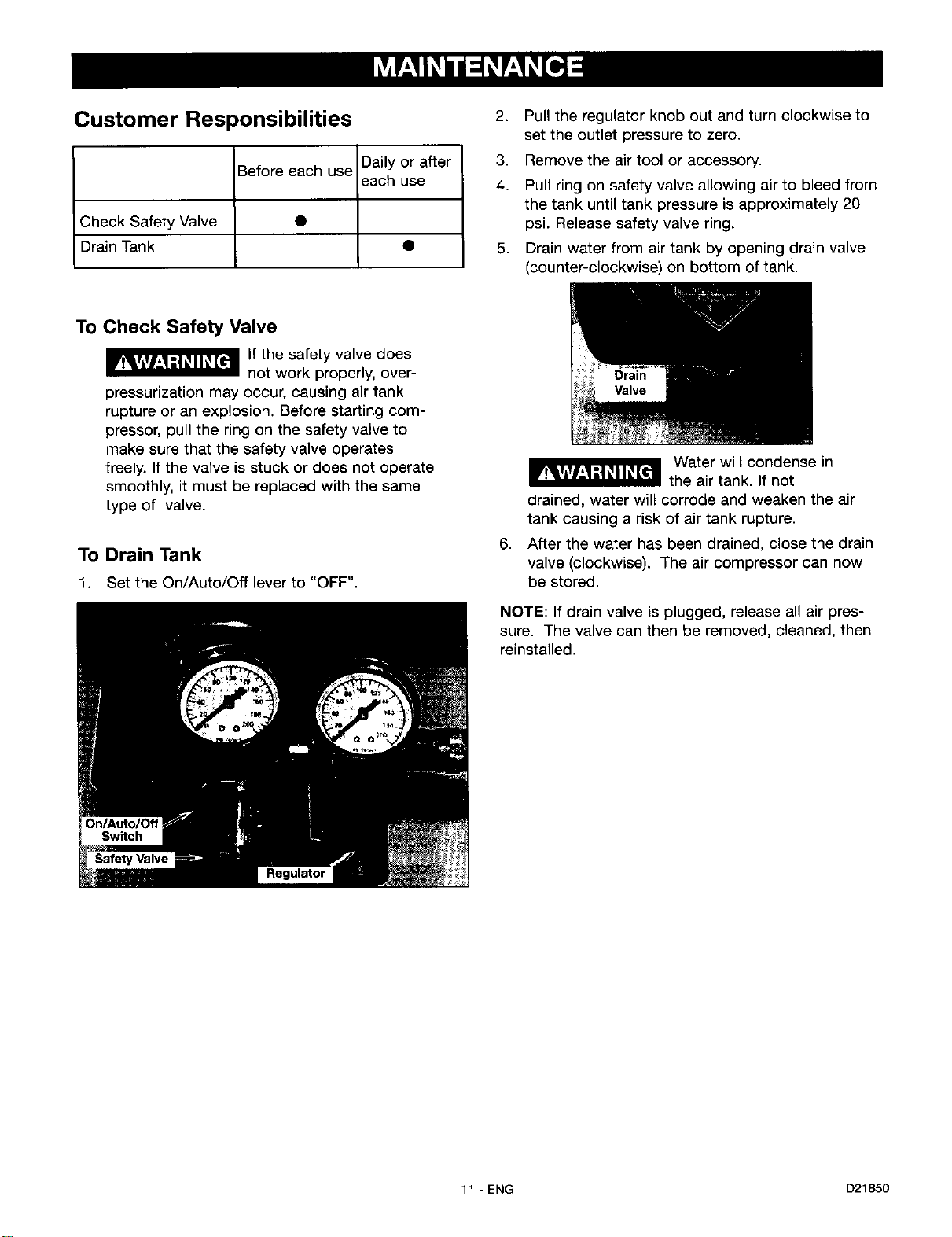
5. Drain water from air tank by opening drain valve
(counter-clockwise) on bottom of tank.
To Check Safety Valve
If the safety valve does
not work properly, over-
pressurization may occur, causing air tank
rupture or an explosion. Before starting com-
pressor, pull the ring on the safety valve to
make sure that the safety valve operates
freely. If the valve is stuck or does not operate
smoothly, it must be replaced with the same
type of valve.
To Drain Tank
1. Set the On/Auto/Oft lever to "OFF".
6,
Valve
Water will condense in
the air tank. If not
drained, water will corrode and weaken the air
tank causing a risk of air tank rupture.
After the water has been drained, close the drain
valve (clockwise). The air compressor can now
be stored.
NOTE: If drain valve is plugged, release all air pres-
sure. The valve can then be removed, cleaned, then
reinstalled.
11- ENG D21850
_Unit cycles automatically when power is on. When doing Maintenance, you may be exposed
to voltage sources, compressed air or moving parts. Personal injuries can occur. Before per-
forming any Maintenance or repair, unplug the compressor and bleed off all air pressure.
ALL MAINTENANCE AND REPAIR OPERATIONS NOT LISTED MUST BE PERFORMED BY
TRAINED SERVICE TECHNICIAN.
Before servicing:
• Unplug or disconnect electrical supply to the
air compressor.
• Bleed tank of pressure. 2.
• Allow the air compressor to cool. 3.
To Replace or Clean Check Valve
1. Release all air pressure from air tank. See "To
Drain Tank" in the Maintenance section.
2. Unplug outfit.
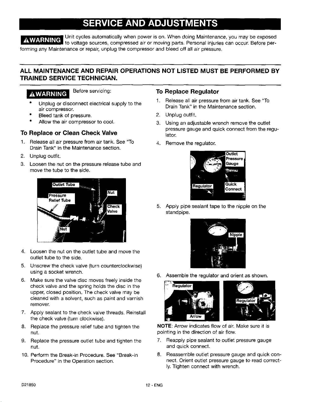
3. Loosen the nut on the pressure release tube and
move the tube to the side.
To Replace Regulator
1. Release all air pressure from air tank. See "To
Drain Tank" in the Maintenance section.
Unplug outfit.
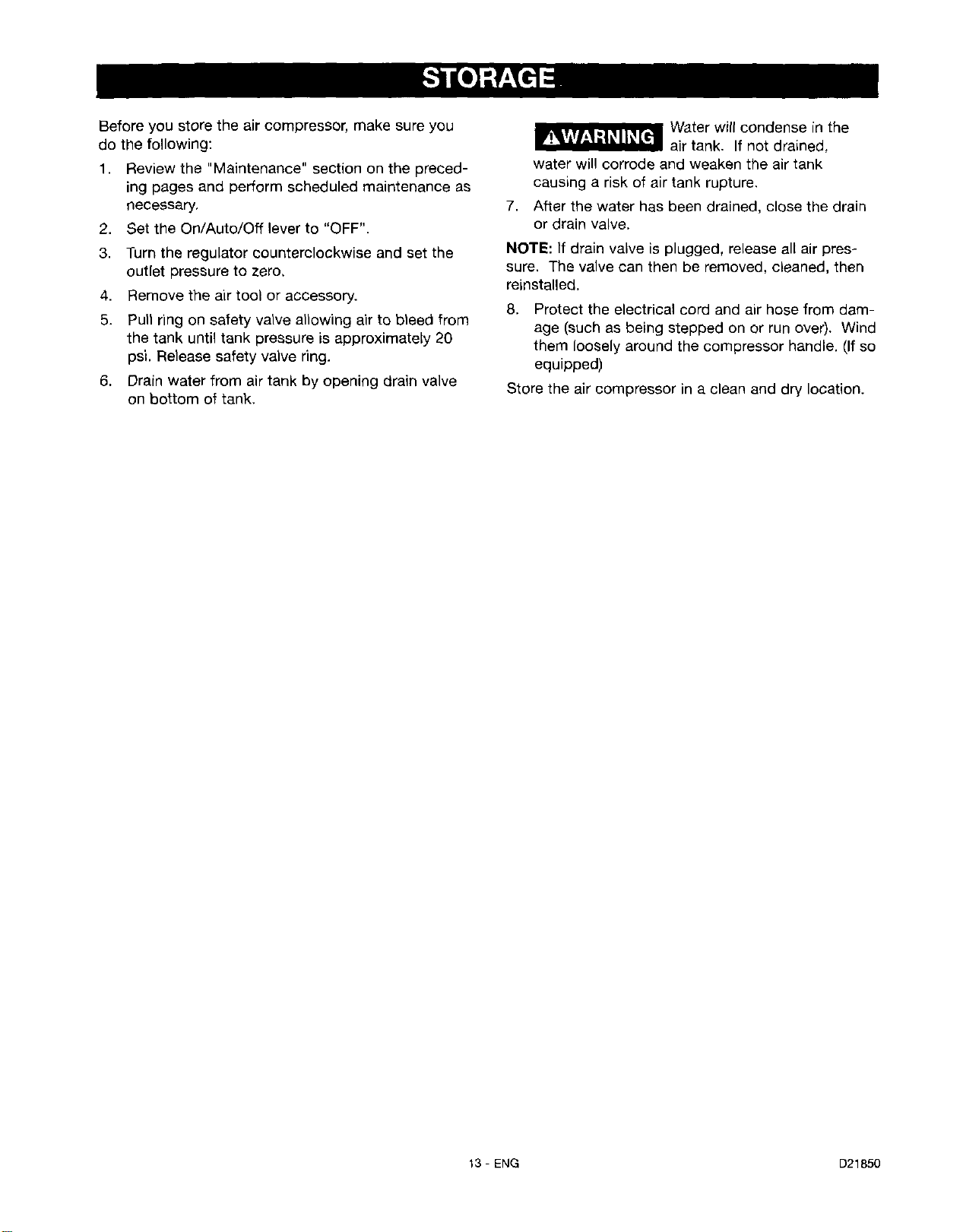
Using an adjustable wrench remove the outlet
pressure gauge and quick connect from the regu-
lator.
4. Remove the regulator.
Outlet Tube
5. Apply pipe sealant tape to the nipple on the
standpipe.
4. Loosen the nut on the outlet tube and move the
outlet tube to the side.
5,
6.
Unscrew the check valve (turn counterclockwise)
using a socket wrench.
Make sure the valve disc moves freely inside the
check valve and the spring holds the disc in the
upper, closed position. The check valve may be
cleaned with a solvent, such as paint and varnish
remover.
7. Apply sealant to the check valve threads. Reinstall
the check valve (turn clockwise).
8. Replace the pressure relief tube and tighten the
nut.
9. Replace the pressure outlet tube and tighten the
nut.
10. Perform the Break-in Procedure, See "Break-in
Procedure" in the Operation section.
6. Assemble the regulator and orient as shown.
NOTE: Arrow indicates flow of air. Make sure it is
pointing in the direction of air flow.
7. Reapply pipe sealant to outlet pressure gauge
and quick connect.
8. Reassemble outlet pressure gauge and quick con-
nect. Orient outlet pressure gauge to read correct-
ly. Tighten connect with wrench.
D21850 12-ENG
Before you store the air compressor, make sure you
do the following:
1. Review the "Maintenance" section on the preced-
ing pages and perform scheduled maintenance as
necessary,
2. Set the On/Auto/Off lever to "OFF".
3. Turn the regulator counterclockwise and set the
outlet pressure to zero,
4. Remove the air tool or accessory.
5. Pull ring on safety valve allowing air to bleed from
the tank until tank pressure is approximately 20
psi. Release safety valve ring.
6. Drain water from air tank by opening drain valve
on bottom of tank.
7,
Water will condense in the
air tank. If not drained,
water will corrode and weaken the air tank
causing a risk of air tank rupture,
After the water has been drained, close the drain
or drain valve.
NOTE: If drain valve is plugged, release all air pres-
sure. The valve can then be removed, cleaned, then
reinstalled.
8. Protect the electrical cord and air hose from dam-
age (such as being stepped on or run over). Wind
them loosely around the compressor handle. (If so
equipped)
Store the air compressor in a clean and dry location.
13-ENG D21850
Performing repairs may expose voltage sources, moving parts or compressed air sources,
moving parts or compressd air sources. Personal injury may occur. Prior to attempting any
repairs, unplug the air compressor and bleed off all air tank air pressure.
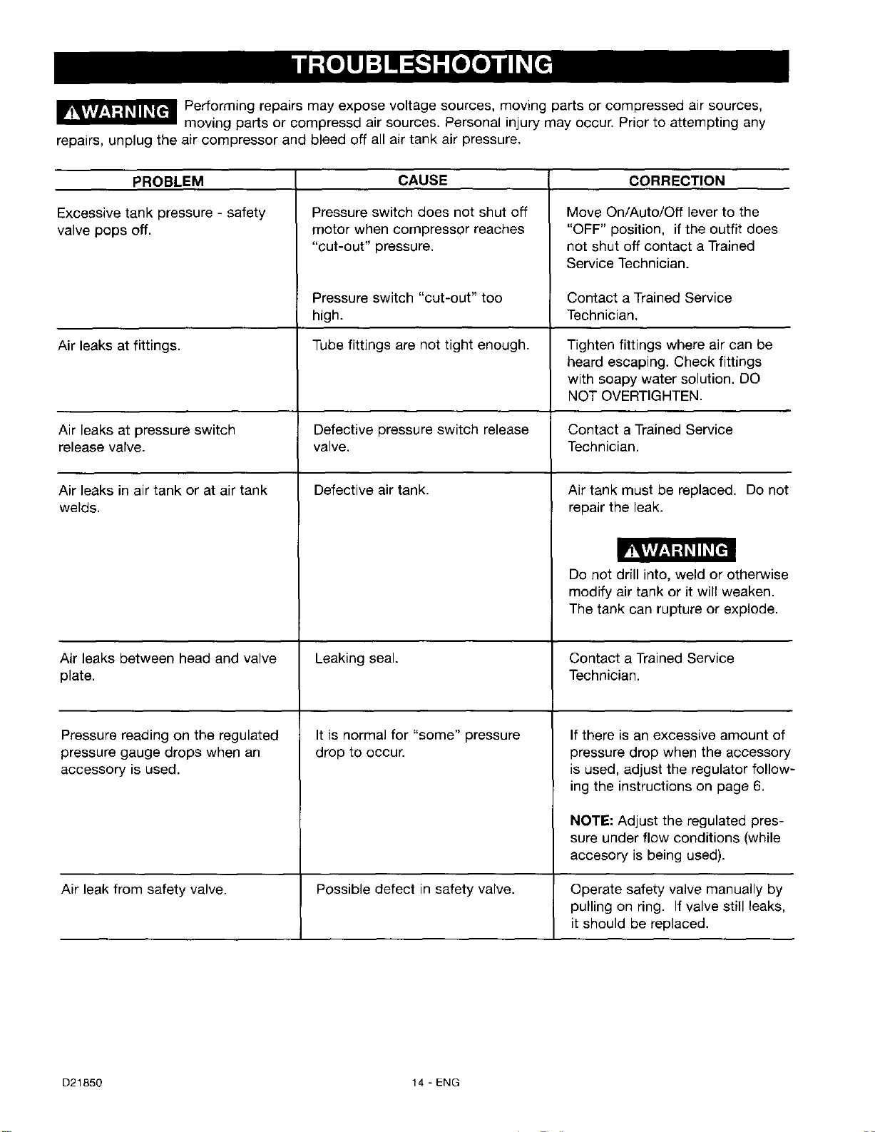
PROBLEM
Excessive tank pressure - safety
valve pops off.
Air leaks at fittings.
CAUSE CORRECTION
Pressure switch does not shut off
motor when compressor reaches
"cut-out" pressure.
Pressure switch "cut-out" too
high.
Tube fittings are not tight enough.
Move On/Auto/Off lever to the
"OFF" position, if the outfit does
not shut off contact a Trained
Service Technician.
Contact a Trained Service
Technician.
Tighten fittings where air can be
heard escaping. Check fittings
with soapy water solution. DO
NOT OVERTIGHTEN.
Air leaks at pressure switch Defective pressure switch release Contact a Trained Service
release valve, valve, Technician.
Air leaks in air tank or at air tank Defective air tank. Air tank must be replaced. Do not
welds, repair the leak.
Pressure reading on the regulated
pressure gauge drops when an
accessory is used.
Do not drill into, weld or otherwise
modify air tank or it will weaken.
The tank can rupture or explode.
Air leaks between head and valve Leaking seal. Contact a Trained Service
plate. Technician.
It is normal for "some" pressure
drop to occur.
If there is an excessive amount of
pressure drop when the accessory
is used, adjust the regulator follow-
ing the instructions on page 6.
NOTE: Adjust the regulated pres-
sure under flow conditions (while
accesory is being used).
Air leak from safety valve. Possible defect in safety valve. Operate safety valve manually by
pulling on ring. If valve still leaks,
it should be replaced.
D21850 14 - ENG
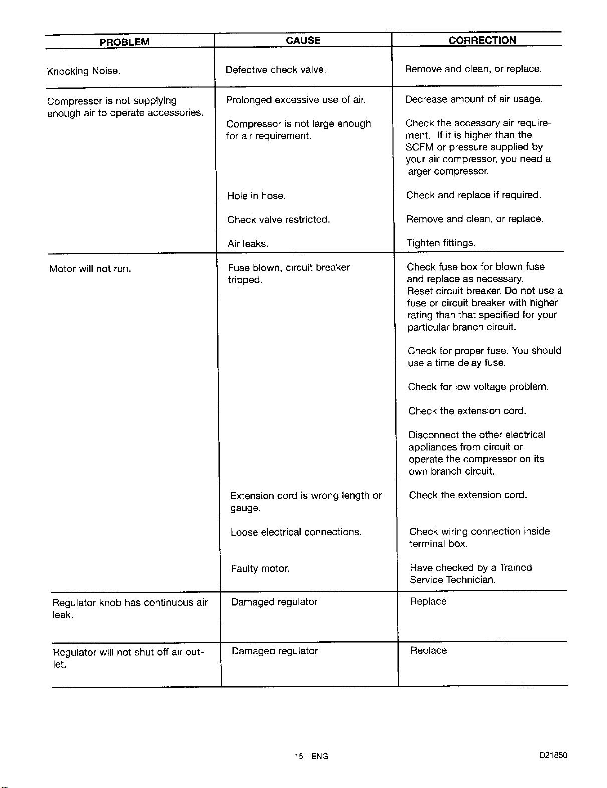
PROBLEM
Knocking Noise.
Compressor is not supplying
enough air to operate accessories.
CAUSE
Defective check valve.
Prolonged excessive use of air.
Compressor is not large enough
for air requirement.
Motor will not run.
Hole in hose.
Check valve restricted.
Air leaks.
Fuse blown, circuit breaker
tripped.
Extension cord is wrong length or
gauge.
Loose electrical connections.
CORRECTION
Remove and clean, or replace.
Decrease amount of air usage.
Check the accessory air require-
ment. If it is higher than the
SCFM or pressure supplied by
your air compressor, you need a
larger compressor.
Check and replace if required.
Remove and clean, or replace.
Tighten fittings.
Check fuse box for blown fuse
and replace as necessary.
Reset circuit breaker. Do not use a
fuse or circuit breaker with higher
rating than that specified for your
particular branch circuit.
Check for proper fuse. You should
use a time delay fuse.
Check for low voltage problem.
Check the extension cord.
Disconnect the other electrical
appliances from circuit or
operate the compressor on its
own branch circuit.
Check the extension cord.
Check wiring connection inside
terminal box.
Faulty motor. Have checked by a Trained
Service Technician.
Regulator knob has continuous air Damaged regulator Replace
leak.
Regulator will not shut off air out- Damaged regulator Replace
let.
15-ENG D21850

D21850 30-SP

31-SP D21850
Get it fixed, at your home or ours!
For repair of major brand appliances in your own home...
no matter who made it, no matter who sold it!
1-800-4-MY-HOME sMAnytime, day or night
(1-800-469-4663)
www.sears.com
To bring in products such as vacuums, lawn equipment and electronics
for repair, call for the location of your nearest Sears Parts & Repair Center.
1-800-488-1222 Anytime, day or night
www.sears.com
For the replacement parts, accessories and owner's manuals
that you need to do-it-yourself, call Sears PartsDirectSM!
1-800-366-PART 6 a.m.- 11 p.m. CST,
(1-800-366-7278) 7 days a week
www.sears.com/partsdirect
To purchase or inquire about a Sears Service Agreement:
1-800-827-6655
7 a.m. - 5 p.m. CST, Mon.- Sat.
Para pedir servicio de reparaci6n a domicilio,
y para ordenar piezas con entrega a domicilio:
1-888-SU-HOGAR sM
(1-888-784-6427)
Au Canada pour service en fran£ais:
1-877-LE-FOYER sM
SEARS
HomeCentralSMj
(1-877-533-6937)
© Sears. Roebuck and Co.
® Registered Trademark / TM Trademark of Sears, Roebuck and Co.
® Marca Registrada / TM Marca de F&brica de Sears, Roebuck and Co.
D21850 32- SP