
Owner's Manual
.0 HP
ELECTRIC ;TART
42" MOWER
AUTOMATIC
1
LAWN TRACTOR
Model No.
917.270642
o Safety
Assembly
o Operation
o Maintenance
o Repair Parts
CAUTION:
Read and follow all
Safety Rules and Instructions
before operating this equip-
ment.
For answers to your questions
about this product, Call:
1=800-659-5917
Sears Craftsman Help Line
5 am - 5 pro, Mon- Sat
Sears, Roebuck and Co., Hoffman Estates, IL 60179
Warranty ................................................. 2
Safety Rules ........................................... 2
Product Specifications ............................ 5
Assembly ................................................ 6
Operation ............................................... 1t
Maintenance Schedule ......................... 18
Maintenance .......................................... 18
Service and Adjustments ...................... 22
Storage .................................................. 28
Troubleshooting .................................... 30
Repair Parts ......................................... 34
Parts Ordering ....................... Back Cover
LIMITED TWO YEAR WARRANTY ON CRAFTSMAN RIDING EQUIPMENT
For two (2) years from the date of purchase, if this Craftsman Riding Equipment is main-
tained, lubricated and tuned up according to the instructions in the owner's manual,
Sears will repair or replace, free of charge, any parts found to be defective in material or
workmanship.
This Warranty does not cover:
o Expendable items which become worn during normal use, such as blades, spark
plugs, air cleaners, belts, etco
• Tire replacement or repair caused by punctures from outside objects, such as nails,
thorns, stumps, or glass.
o Repairs necessary because of operator abuse, negligence, improper storage or acci-
dent or the failure to maintain the equipment according to the instructions contained in
the owner's manual.
o Riding equipment used for commercial or rental purposes.
LIMITED 90 DAY WARRANTY ON BATTERY
For ninety (90) days from date of purchase, if any battery included with this riding equip-
ment proves defective in material or workmanship and our testing determines the bat-
tery will not hold a charge, Sears will replace the battery at no charge. In-home warranty
service on your Craftsman riding equipment is available at no charge for 30 days from
the date of purchase. Please contact your nearest service center. After 30 days from the
date of purchase, warranty service is available by taking your Craftsman riding equip-
ment to your nearest Sears Service Center. (In-home warranty service will still be avail-
able after 30 days from the date of purchase but a standard trip charge will apply). This
warranty applies only while this product is in the United States. This Warranty gives you
specific legal rights, and you may also have other rights which may vary from state to
state.
Sears, Roebuck and Co, D/817 WA, Hoffman Estates, IL 60179
GENERAL OPERATION
o Read, understand, and follow all instruc-
tions in the manual and on the machine
before starting°
° Only allow responsible adults, who are
familiar with the instructions, to operate
the machine_
o Clear the area of objects such as rocks,
toys, wire, etco, which could be picked
up and thrown by the blade.
- Be sure the area is clear of other people
before mowing. Stop machine if anyone
enters the area.
2
o Never carry passengers.
° Do not mow in reverse unless absolute-
ly necessary. Always look down and
behind before and while backing.
• Be aware of the mower discharge direc-
tion and do not point it at anyone. Do
not operate the mower without either
the entire grass catcher or the guard in
place.
o Slow down before turning.
° Never leave a running machine unat-
tended. Always turn off blades, set park-
ing brake, stop engine, and remove
keys before dismounting.
• Turn off blades when not mowing.
- Stop engine before removinggrass
catcher or uncloggingchute°
o Mow only in daylight or good artificial
light.
° Do not operate the machine while under
the influence of alcohol or drugs.
o Watchfor traffic when operating near or
crossing roadways.
° Use extra care when loading or unload-
ing the machine into a trailer or truck.
SLOPE OPERATION
Slopes are a major factor related to loss-
of-control and tipover accidents, which
can result in severe injury or death. All
slopes require extra caution. If you cannot
back up the slope or if you fee! uneasy on
it, do not mow it.
DO:
o Mow up and down slopes, not across_
° Remove obstacles such as rocks, tree
limbs, etc.
° Watch for holes, ruts, or bumps. Uneven
terrain could overturn the machine. Tall
grass can hide obstacles.
o Use slow speed. Choose a low gear so
that you will not have to stop or shift
while on the slope.
o Follow the manufacturer's recommen-
dations for wheel weights or counter-
weights to improve stability.
o Use extra care with grass catchers or
other attachments. These can change
the stability of the machine.
° Keep all movement on the slopes slow
and gradual. Do not make sudden
changes in speed or direction_
° Avoid starting or stopping on a slope. If
tires lose traction, disengage the blades
and proceed slowly straight down the
slope.
DO NOT:
o Do not turn on slopes unless necessary,
and then, turn slowly and gradually
downhill, if possible.
o Do not mow near drop-offs, ditches, or
embankments° The mower could sud-
denly turn over if a wheel is over the
edge of a cliff or ditch, or if an edge
caves in.
o Do not mow on wet grass. Reduced
traction could cause sliding_
o Do not try to stabilize the machine by
putting your foot on the ground.
o Do not use grass catcher on steep
slopes.
CHILDREN
Tragic accidents can occur if the operator
is not alert to the presence of children.
Children are often attracted to the
machine and the mowing activity. Never
assume that children will remain where
you last saw them.
• Keep children out of the mowing area
and under the watchful care of another
responsible adult.
o Be alert and turn machine off if children
enter the area.
o Before and when backing, look behind
and down for small children_
• Never carry children. They may fall off
and be seriously injured or interfere with
safe machine operation.
o Never allow children to operate the
machine_
° Use extra care when approaching blind
corners, shrubs, trees._ or other objects
that may obscure vision.
SERVICE
o Use extra care in handling gasoline and
other fuels. They are flammable and
vapors are explosive.
Use only an approved container.
Never remove gas cap or add fuel
with the engine running. Allow en-
gine to cool before refueling. Do not
smoke.
Never refuel the machine indoors.
Never store the machine or fuel
container inside where there is an
open flame, such as a water heater.
° Never run a machine inside a closed
area.
° Keep nuts and bolts, especially blade
attachment bolts, tight and keep equip-
ment in good condition.
° Never tamper with safety devices.
Check their proper operation regularly.
° Keep machine free of grass, leaves, or
other debris build-up. Clean oil or fuel
spillage. Allow machine to cool before
storing.
o Stop and inspect the equipment if you
strike an object. Repair, if necessary,
before restarting.
3
o
o
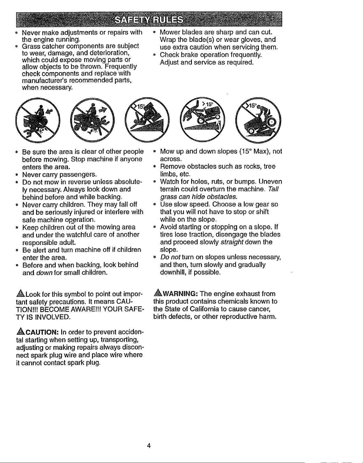
Never make adjustments or repairs with
the engine running.
Grass catcher components are subject
to wear, damage, and deterioration,
which could expose moving parts or
allow objects to be thrown. Frequently
check components and replace with
manufacturer's recommended parts,
when necessary.
o Be sure the area is clear of other people
before mowing. Stop machine if anyone
enters the area.
• Never carry passengers.
o Do not mow in reverse unless absolute-
ly necessary. Always look down and
behind before and while backing.
o Never carry children. They may fall off
and be seriously injured or interfere with
safe machine oRerationo
• Keep children out of the mowing area
and under the watchful care of another
responsible adult.
° Be alert and turn machine off if children
enter the area.
° Before and when backing, look behind
and down for small children.
o Mower blades are sharp and can cut.
Wrap the blade(s) or wear gloves, and
use extra caution when servicing them.
Check brake operation frequently.
Adjust and service as required.
o Mow up and down slopes (t5 ° Max), not
across.
• Remove obstacles such as rocks, tree
limbs, etc.
o Watch for holes, ruts, or bumps_ Uneven
terrain could overturn the machine. Tall
grass can hide obstacles.
o Use slow speed. Choose a low gear so
that you wilt not have to stop or shift
while on the stope_
• Avoid starting or stopping on a slope. If
tires lose traction, disengage the blades
and proceed slowly straight down the
slope.
o Do not turn on slopes unless necessary,
and then, turn slowly and gradually
downhill, if possible.
,_Look for this symbol to point out impor-
tant safety precautions. It means CAU-
TION!!! BECOME AWARE!!! YOUR SAFE-
TY IS INVOLVED°
,_CAUTION: In order to prevent acciden-
tal starting when setting up, transporting,
adjusting or making repairs always discon-
nect spark plug wire and place wire where
it cannot contact spark plug.
,_WARNING: The engine exhaust from
this product contains chemicals known to
the State of California to cause cancer,
birth defects, or other reproductive harm.
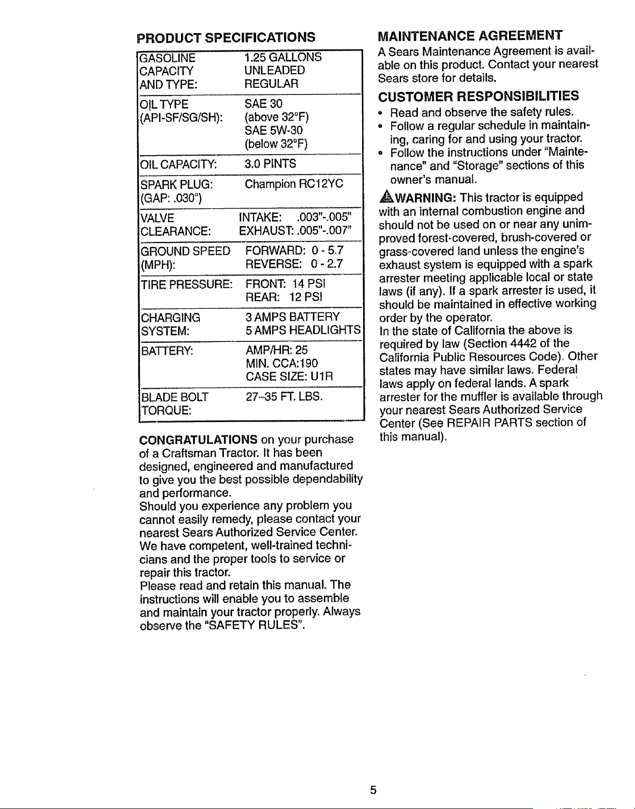
PRODUCT SPECIFICATIONS
GASOLINE 1.25 GALLONS
CAPACITY UNLEADED
AND TYPE: REGULAR
O!L TYPE SAE 30
(API-SF!SG/SH): (above 32°F)
SAE 5W-30
(below 32°F)
OIL CAPACITY: 3,0 PINTS
SPARK PLUG: Champion RC12YC
(GAP: .030")
VALVE INTAKE: o003"-_005"
;LEARANCE: EXHAUST: .005"-.007"
'GROUND SPEED FORWARD: 0-5.7
MPH): REVERSE: 0- 2.7
TIRE PRESSURE: FRONT: 14PSI
REAR: 12 PSt
;HARGING 3 AMPS BATTERY
;YSTEM: 5 AMPS HEADLIGHTS
BATTERY: AMP/HR: 25
MIN. CCA:190
CASE SIZE: UtR
BLADE BOLT 27-35 FT. LBS.
TORQUE:
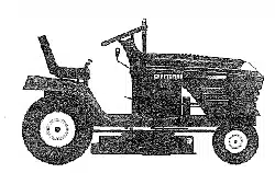
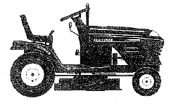
CONGRATULATIONS on your purchase
of a Craftsman Tractor. It has been
designed, engineered and manufactured
to give you the best possible dependability
and performance.
Should you experience any problem you
cannot easily remedy, please contact your
nearest Sears Authorized Service Center.
We have competent, well-trained techni-
cians and the proper tools to service or
repair this tractor.
Please read and retain this manual. The
instructions will enable you to assemble
and maintain your tractor properly. Always
observe the "SAFETY RULES".
MAINTENANCE AGREEMENT
A Sears Maintenance Agreement is avail-
able on this product. Contact your nearest
Sears store for details.
CUSTOMER RESPONSIBILITIES
• Read and observe the safety rules.
o Follow a regular schedule in maintain-
ing, caring for and using your tractor.
• Follow the instructions under "Mainte-
nance" and "Storage" sections of this
owner's manual°
_kWARNING: This tractor is equipped
with an internal combustion engine and
should not be used on or near any unim-
proved forest-covered, brush-covered or
grassocovered land unless the engine's
exhaust system is equipped with a spark
arrester meeting applicable local or state
laws (if any)° If a spark arrester is used, it
should be maintained in effective working
order by the operator.
In the state of California the above is
required by law (Section 4442 of the
California Public Resources Code), Other
states may have similar laws. Federal
laws apply on federal lands. A spark
arrester for the muffler is available through
your nearest Sears Authorized Service
Center (See REPAIR PARTS section of
this manual).
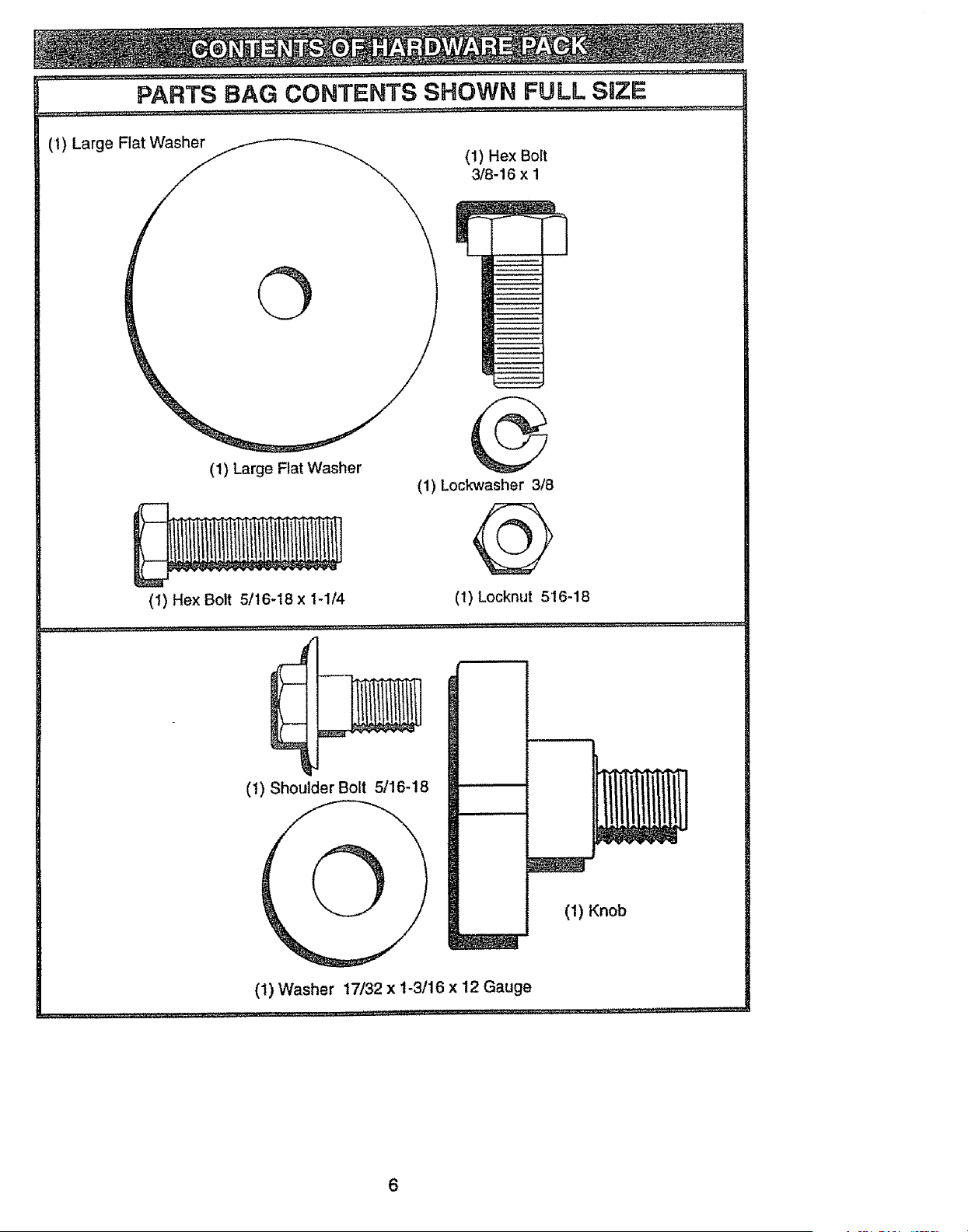
PARTS BAG CONTENTS SHOWN FULL SIZIE
(t) Large Flat Washer
(1) Hex Bolt
3/8-16 x 1
©
(1) Large Flat Washer
(1) Lockwasher 3/8
@
(1) Hex Bolt 5/16-t8 x 1-1/4 (I) Locknut 516-18
(1) Shoulder Bolt 5/16-18
O
(1) Knob
(1) Washer 17/32 x 1-3/16 x 12 Gauge
6
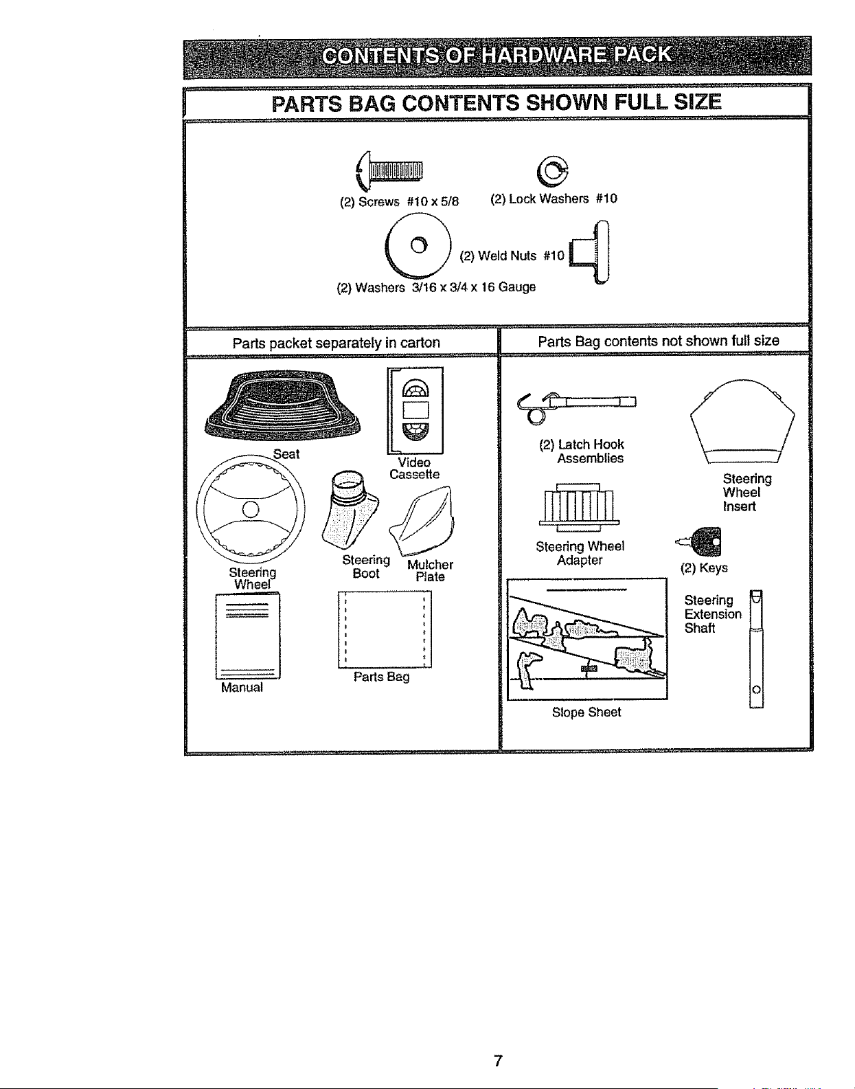
PARTS BAG CONTENTS SHOWN FULL SiZE
(2) Screws #10 x 5/8 (2) Lock Washers #10
(2) Washers 3/16 x 3/4 x 16 Gauge
Parts packet separately in carton
........................... ,.4_L .............• u ,J_............. ,.Ju ............
F-]
Steering
Wheel
Manual
Video
Cassette
Steering Mulcher
Boot Plate
I I
ii t
il
I t
Parts Bag
Parts Bag contents not shown full size
(2) Latch Hook
Assemblies
Steering Wheel ,c_
Adapter (2) Keys
Slope Sheet
Steering
Wheel
Insert
Steering
Extension
Shaft =
_i
Your new tractor has been assembled at the factory with exception of those parts left
unassembled for shipping purposes. To ensure safe and proper operation of your tractor
all parts and hardware you assemble must be tightened securely. Use the correct tools
as necessary to insure proper tightness. Review the video cassette before you begin.
TOOLS REQUIRED FOR
ASSEMBLY
A socket wrench set will make assembly
easier. Standard wrench sizes you need
are listed below.
(1) 9/16" wrench
(1)Pliers
(2) 1/2" wrench
(1) 3/4" wrench
(1) Utility knife
(1) 3/4" Socket w/
drive rachet
(1) Phillips Screw-
driver
(1) Tire pressure
gauge
When right or left hand is mentioned in
this manual, it means, from your point of
view, when you are in the operating posi-
tion (seated behind the steering wheel).
TO REMOVE TRACTOR FROM
CARTON
UNPACK CARTON
= Remove all accessible loose parts and
parts boxes from shipping carton (See
page 6).
• Cut, from top to bottom, along lines on
all four corners of shipping carton, and
lay panels flaL
o Check for any additional loose parts or
boxes and remove.
BEFORE ROLLING TRACTOR OFF
SKiD
ATTACH STEERING WHEEL
ASSEMBLE EXTENSION SHAFT AND
BOOT
o Slide extension shaft onto lower steer-
ing shaft. Align mounting holes in exten-
sion and lower shafts and install 5/16
hex bolt and iocknut. Tighten securely.
IMPORTANT: Tighten bolt and nut secure-
ly to 18-22 ft. Ibs. torque.
o Place tabs of steering boot over tab
slots in dash and push down to secure.
INSTALL STEERING WHEEL
- Position front wheels of the tractor so
they are pointing straight forward.
o Slide steering wheel adapter onto steer-
ing shaft extension.
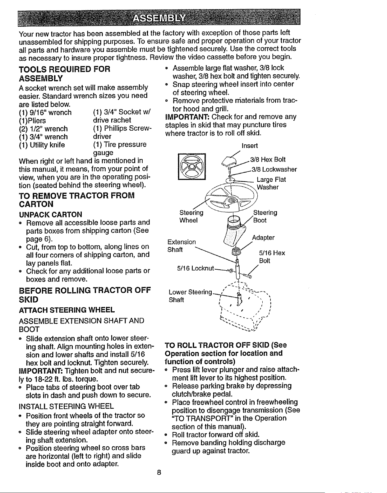
• Position steering wheel so cross bars
are horizontal (left to right) and slide
inside boot and onto adapter.
° Assemble large flat washer, 3/8 lock
washer, 3/8 hex bolt and tighten securely.
° Snap steering wheel insert into center
of steering wheel.
o Remove protective rfiaterials from trac-
tor hood and grill.
IMPORTANT: Check for and remove any
staples in skid that may puncture tires
where tractor is to roll off skid.
Insert
318 Hex Bolt
318 Lockwasher
Large Flat
Washer
TO ROLL TRACTOR OFF SKID (See
Operation section for location and
function of controls)
o Press lift lever plunger and raise attach-
ment lift lever to its highest position.
° Release parking brake by depressing
clutch/brake pedal.
° Place freewheel control in freewheeling
position to disengage transmission (See
"TO TRANSPORT" in the Operation
section of this manual).
• Roll tractor forward off skid.
• Remove banding holding discharge
guard up against tractor.
8
HOW TO SET UP YOUR TRACTOR
CHECK BATTERY
o Lift seat pan to raised postion and open
battery box door,
° If this battery is put into service after
month and year indicated on label (label
located between terminals) charge bat-
tery for minimum of one hour at 6-10
amps. (See "BATTERY" in MAINTE-
NANCE section of this manual for charg-
ing structions.)
Seat
Battery
Door
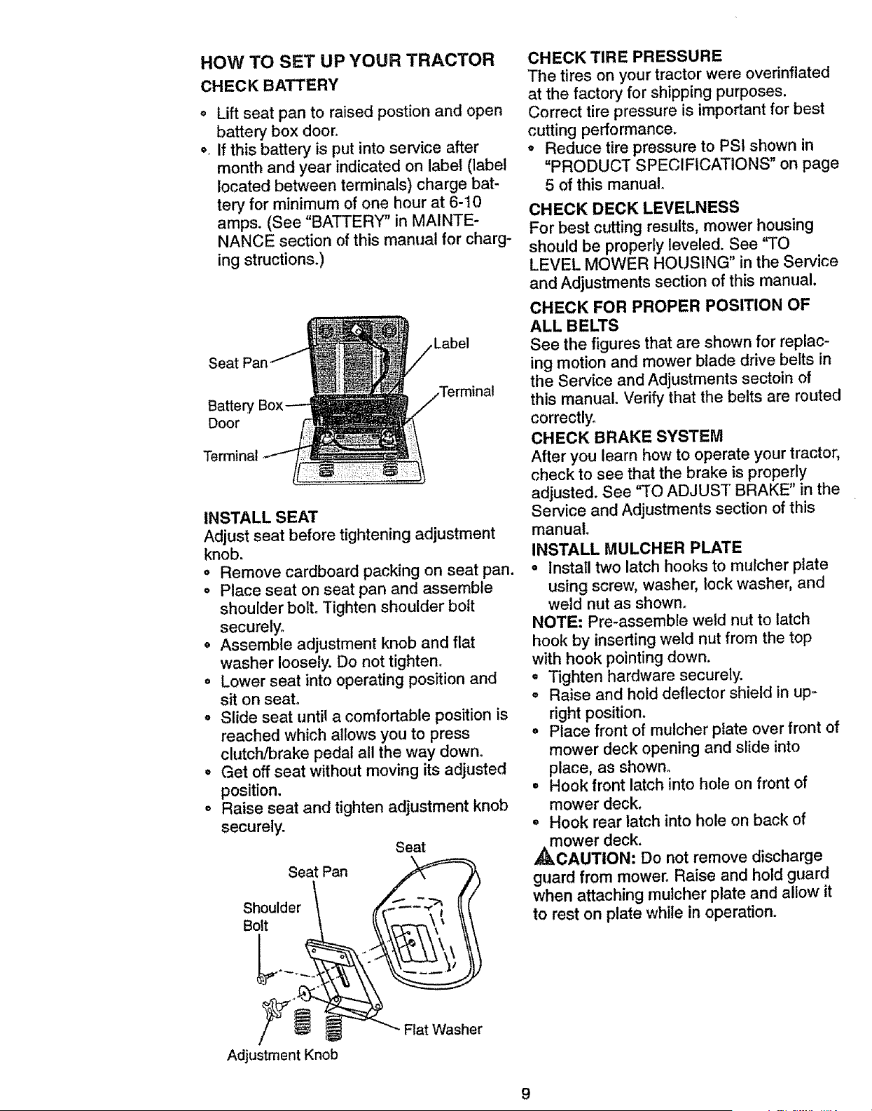
INSTALL SEAT
Adjust seat before tightening adjustment
knob.
o Remove cardboard packing on seat pan.
o Place seat on seat pan and assemble
shoulder bolt. Tighten shoulder bolt
securely.
• Assemble adjustment knob and flat
washer loosely. Do not tighten.
• Lower seat into operating position and
sit on seat°
° Slide seat until a comfortable position is
reached which allows you to press
clutch/brake pedal all the way down.
° Get off seat without moving its adjusted
position.
• Raise seat and tighten adjustment knob
securely.
Seat
Seat Pan _!
Shoulder
Bolt
Adjustment Knob
Flat Washer
CHECK TIRE PRESSURE
The tires on your tractor were overinflated
at the factory for shipping purposes.
Correct tire pressure is important for best
cutting performance.
• Reduce tire pressure to PSI shown in
"PRODUCT SPECIFICATIONS" on page
5 of this manual°
CHECK DECK LEVELNESS
For best cutting results, mower housing
should be properly leveled. See "TO
LEVEL MOWER HOUSING" in the Service
and Adjustments section of this manual.
CHECK FOR PROPER POSITION OF
ALL BELTS
See the figures that are shown for replac-
ing motion and mower blade drive belts in
the Service and Adjustments sectoin of
this manual. Verify that the belts are routed
correctly.
CHECK BRAKE SYSTEM
After you learn how to operate your tractor,
check to see that the brake is properly
adjusted. See "TO ADJUST BRAKE" in the
Service and Adjustments section of this
manual.
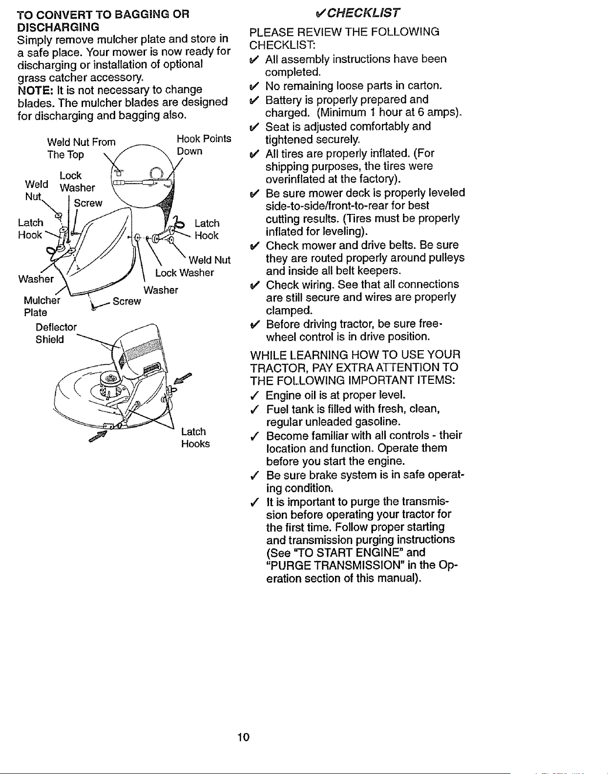
INSTALL MULCHER PLATE
• Install two latch hooks to mulcher plate
using screw, washer, lock washer, and
weld nut as shown.
NOTE: Pre-assemble weld nut to latch
hook by inserting weld nut from the top
with hook pointing down.
, Tighten hardware securely.
o Raise and hold deflector shield in up,-
right position.
o Place front of mulcher plate over front of
mower deck opening and slide into
place, as shown.
° Hook front latch into hole on front of
mower deck.
° Hook rear latch into hole on back of
_kmower deck.
CAUTION: Do not remove discharge
guard from mower_ Raise and hold guard
when attaching mulcher plate and allow it
to rest on plate while in operation.
TO CONVERT TO BAGGING OR
DISCHARGING
Simply remove mulcher plate and store in
a safe place. Your mower is now ready for
discharging or installation of optional
grass catcher accessory.
NOTE; It is not necessary to change
blades. The mulcher blades are designed
for discharging and bagging also.
Weld Nut From Hook Points
Down
The Top ,,_
Lock
Weld Washer
Screw
Latch Latch
Hook
Washer
Mulcher "_I-- Screw
Plate
Deflector
Shield
Nut
Lock Washer
Washer
Latch
Hooks
_/ CHECKLIS T
PLEASE REVIEW THE FOLLOWING
CHECKLIST:
_" All assembly instructions have been
completed.
v" No remaining loose parts in carton.
Battery is properly prepared and
charged. (Minimum I hour at 6 amps).
v' Seat is adjusted comfortably and
tightened securely°
v' All tires are properly inflated. (For
shipping purposes, the tires were
overinflated at the factory).
Be sure mower deck is properly leveled
side-to-side/front-to-rear for best
cutting results. (Tires must be properly
inflated for leveling).
v' Check mower and drive belts. Be sure
they are routed properly around pulleys
and inside all belt keepers.
v" Check wiring. See that all connections
are still secure and wires are properly
clamped.
v' Before driving tractor, be sure free-
wheel control is in drive position.
WHILE LEARNING HOW TO USE YOUR
TRACTOR, PAY EXTRA ATTENTION TO
THE FOLLOWING IMPORTANT ITEMS:
#" Engine oil is at proper level.
J' Fuel tank is filled with fresh, clean,
regular unleaded gasoline.
,/ Become familiar with all controls - their
location and function. Operate them
before you start the engine,
,/ Be sure brake system is in safe operat-
ing condition_
,/ It is important to purge the transmis-
sion before operating your tractor for
the first time. Follow proper starting
and transmission purging instructions
(See "TO START ENGINE" and
"PURGE TRANSMISSION" in the Op-
eration section of this manual).
10

These symbols may appear on your tractor or in literature suppliedwith the product.
Learnand understand their meaning,
BATTERY
ENGINE ON
FUEL
CAUTION OR REVERSE FORWARD SLOW
WARNING
ENGINE OFF OIL PRESSURE LIGHTS ON "_
$
Xl-@ 0
CHOKE MOWER HEIGHT PARKING BRAKE
LOCKED
FAST
OVER TEMP
LIGHT
UNLOCKED MOWER LIFT
ATTACHMENT
CLUTCH ENGAGED
IGNITION
REVERSE NEUTRAL HIGH
ATTACHMENT
CLUTCH DISENGAGED
L
LOW PARKING BRAKE
@@@
KEEP AREA CLEAR SLOPE HAZARDS
(SEE SAFETY RULES SECTION)
DANGER_ KEEP HANDS AND FEET AWAY
FREE WHEEL
(Automatic Models only)
11
KNOW YOUR TRACTOR
READ THIS OWNER'S MANUAL AND SAFETY RULES BEFORE OPERATING
YOUR TRACTOR
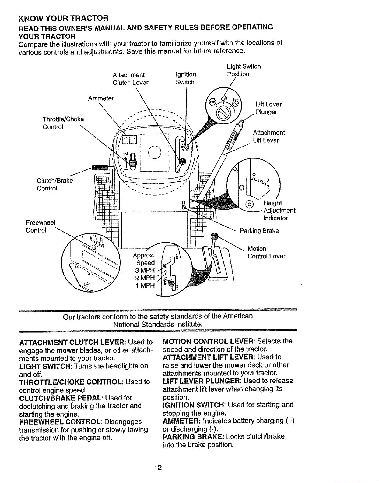
Compare the illustrations with your tractor to familiarize yourself with the locations of
various controls and adjustments Save this manual for future reference.
Attachment Ignition
Clutch Lever Switch
Light Switch
Position
ThrottletChoke
Control
Ammeter
©
Lift Lever
Plunger
Attachment
Lift Lever
Clutch/Brake
Control
Freewheel
Control
Height
Adjustment
Indicator
Parking Brake
Approx.
Speed
3 MPH
2 MPH
1 MPH
Motion
Control Lever
Jt,lll,l ......... , ................ '[[_.LJ L ........... , ........................................
Our tractors conform to the safety standards of the American
National Standards Institute.
ATTACHMENT CLUTCH LEVER: Used to
engage the mower blades, or other attach-
ments mounted to your tractor.
LIGHT SWITCH: Turns the headlights on
and off.
THROTTLE/CHOKE CONTROL: Used to
control engine speed.
CLUTCH/BRAKE PEDAL: Used for
declutching and braking the tractor and
starting the engine.
FREEWHEEL CONTROL: Disengages
transmission for pushing or slowly towing
the tractor with the engine off.
MOTION CONTROL LEVER: Selects the
speed and direction of the tractor.
ATTACHMENT LIFT LEVER: Used to
raise and lower the mower deck or other
attachments mounted to your tractor.
LIFT LEVER PLUNGER: Used to release
attachment lift lever when changing its
position.
IGNITION SWITCH: Used for starting and
stopping the engine.
AMMETER: indicates battery charging (+)
or discharging (-).
PARKING BRAKE: Locks clutch/brake
into the brake position°
12
The operation of any tractor can result in foreign objects thrown into the
eyes, which can result in severe eye damagerAlways wear safety glasses
or eye shields while operatingyour tractor or performing any adjustmentsor
repairs. We recommenda wide visionsafety maskover the spectacles,or
standard safety glasses
HOW TO USE YOUR TRACTOR
Your tractor is equipped with an operator
presence sensing switch_ When engine is
running, any attempt by the operator to
leave the seat without first setting the
parking brake will shut off the engine.
TO SET PARKING BRAKE
• Depress clutch/brake pedal into full
"BRAKE" position and hold_
o Place parking brake lever in "EN-
GAGED" position and release pressure
from clutch/brake pedal. Pedal should
remain in "BRAKE" position. Make sure
parking brake will hold tractor secure.
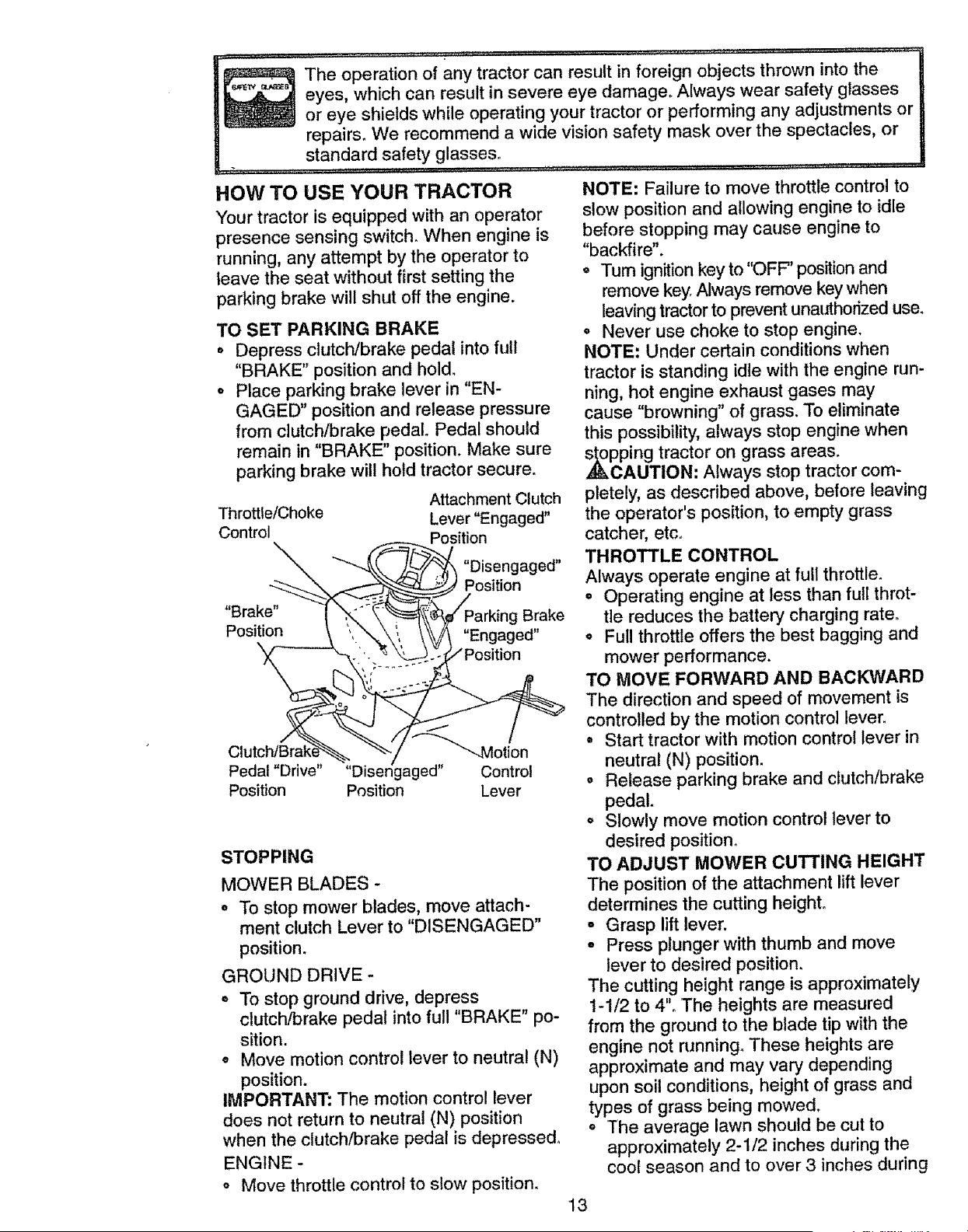
Attachment Clutch
Throttle/Choke Lever "Engaged"
Control
_ Position
_ "Disengaged"
Position
"Brake ,_ Parkin Brake
., g
Pos_t_on u
nga-ed"
• _....... osition
Peda! "Drive" "Disengaged" Control
Position Position Lever
STOPPING
MOWER BLADES -
o To stop mower blades, move attach-
ment clutch Lever to "DISENGAGED"
position.
GROUND DRIVE
o To stop ground drive, depress
clutch/brake pedal into full "BRAKE" po-
sition.
o Move motion control lever to neutral (N)
position.
IMPORTANT." The motion control lever
does not return to neutral (N) position
when the clutch/brake pedal is depressed_
ENGINE -
o Move throttle control to slow position.
NOTE: Failure to move throttle control to
slow position and allowing engine to idle
before stopping may cause engine to
"backfire".
o Turn ignitionkey to "OFF" position and
remove key Always remove key when
leaving tractor to prevent unauthorized use_
° Never use choke to stop engine.
NOTE: Under certain conditions when
tractor is standing idle with the engine run-
ning, hot engine exhaust gases may
cause "browning" of grass. To eliminate
this possibility, always stop engine when
_pping tractor on grass areas.
CAUTION: Always stop tractor com-
pletely, as described above, before leaving
the operator's position, to empty grass
catcher, etco
THROTTLE CONTROL
Always operate engine at full throttle.
o Operating engine at tess than futl throt-
tle reduces the battery charging rate.
o Full throttle offers the best bagging and
mower performance.
TO MOVE FORWARD AND BACKWARD
The direction and speed of movement is
controlled by the motion control lever.
° Start tractor with motion control lever in
neutral (N) position.
o Release parking brake and clutch/brake
pedal.
o Slowly move motion control lever to
desired position°
TO ADJUST MOWER CUTTING HEIGHT
The position of the attachment lift lever
determines the cutting heighL
° Grasp lift lever.
o Press plunger with thumb and move
lever to desired position.
The cutting height range is approximately
1-I/2 to 4". The heights are measured
from the ground to the blade tip with the
engine not running_ These heights are
approximate and may vary depending
upon soil conditions, height of grass and
types of grass being mowed.
° The average lawn should be cut to
approximately 2-1/2 inches during the
coot season and to over 3 inches during
13
hot months. For healthier and better
looking lawns, mow often and after
moderate growth.
o For best cutting performance, grass
over 6 inches in height should be
mowed twice. Make the first cut relative-
ly high; the second to desired height.
TO OPERATE ON HILLS
•_kCAUTION: Do not drive up or down
hills with slopes greater than t5 ° and do
not drive across any slope. Use the slope
guide provided at the back of this manual.
• Choose the slowest speed before start-
ing up or down hills.
,, Avoid stopping or changing speed on
hills.
= If slowing is necessary, move throttle
control lever to slower position.
o If stopping is absolutely necessary, push
clutch!brake pedal quickly to brake posi-
tion and engage parking brake.
- Move motion control lever to neutral (N)
position.
IMPORTANT: The motion control lever
does not return to neutral (N) position
when the clutch/brake pedal is depressed.
• To restart movement, slowly release
parking brake and clutch/brake pedal.
o Slowly move motion control lever to
slowest setting.
o Make all turns slowly.
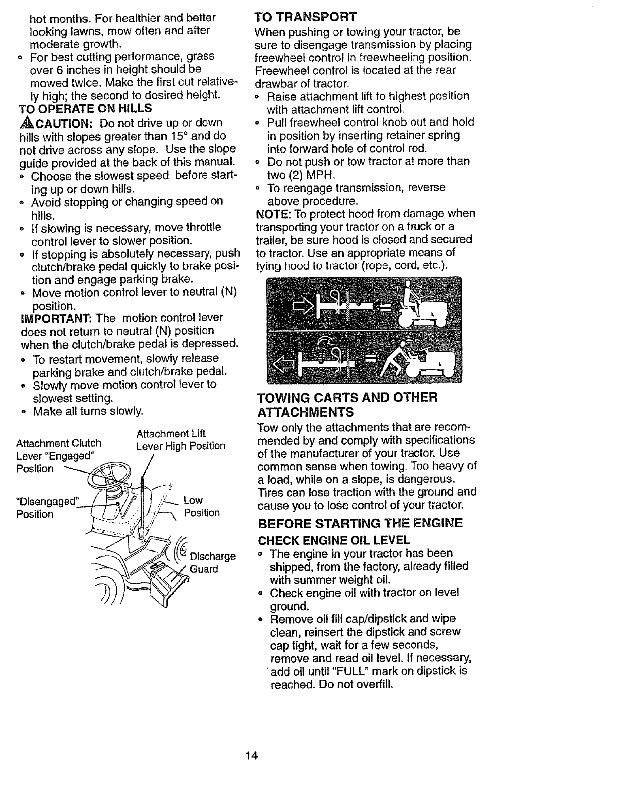
Attachment Clutch
Lever "Engaged"
Position
Attachment Lift
Lever High Position
Position
,,:_ Low
Position
'ge
Guard
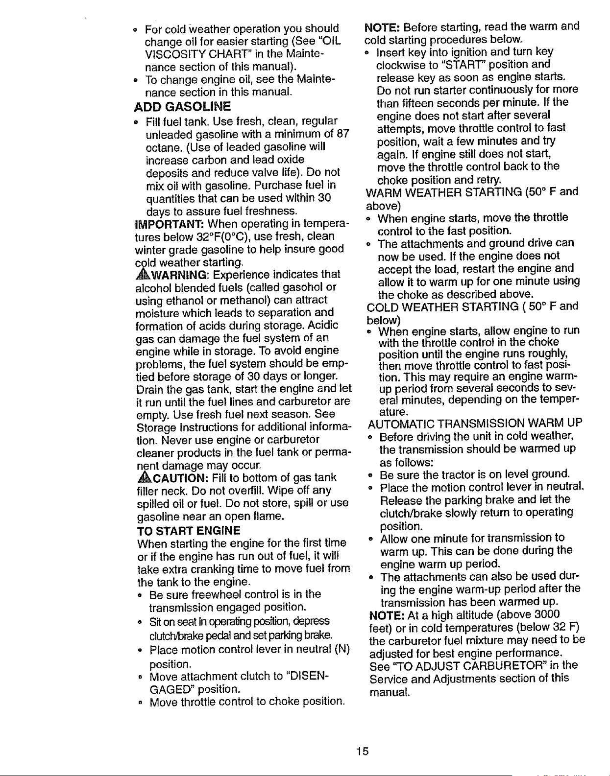
TO TRANSPORT
When pushing or towing your tractor, be
sure to disengage transmission by placing
freewheel control in freewheeling position.
Freewheel control is located at the rear
drawbar of tractor°
o Raise attachment lift to highest position
with attachment lift control..
o Pull freewheel control knob out and hold
in position by inserting retainer spring
into forward hole of control rod.
= Do not push or tow tractor at more than
two (2) MPH.
• To reengage transmission, reverse
above procedure.
NOTE: To protect hood from damage when
transporting your tractor on a truck or a
trailer, be sure hood is closed and secured
to tractor. Use an appropriate means of
tying hood to tractor (rope, cord, etc,).
TOWING CARTS AND OTHER
ATTACHMENTS
Tow only the attachments that are recom-
mended by and comply with specifications
of the manufacturer of your tractor. Use
common sense when towing_ Too heavy of
a load, while on a slope, is dangerous.
Tires can lose traction with the ground and
cause you to lose control of your tractor.
BEFORE STARTING THE ENGINE
CHECK ENGINE OIL LEVEL
• The engine in your tractor has been
shipped, from the factory, already filled
with summer weight oil.
° Check engine oil with tractor on level
ground.
° Remove oil fill cap/dipstick and wipe
clean, reinsert the dipstick and screw
cap tight, wait for a few seconds,
remove and read oil level. If necessary,
add oil until "FULL" mark on dipstick is
reached. Do not overfill
14
• Forcold Weather operation you should
change oil for easier starting (See "OIL
VISCOSITY CHART" in the Mainte-
nance section of this manual).
° To change engine oil, see the Mainte-
nance section in this manual.
ADD GASOLINE
° Fill fuel tank° Use fresh, clean, regular
unleaded gasoline with a minimum of 87
octane. (Use of leaded gasoline will
increase carbon and lead oxide
deposits and reduce valve life). Do not
mix oil with gasoline. Purchase fuel in
quantities that can be used within 30
days to assure fuel freshness.
IMPORTANT: When operating in tempera-
tures below 32°F(0°C), use fresh, clean
winter grade gasoline to help insure good
dAweather starting,
RNING: Experience indicates that
alcohol blended fuels (called gasohol or
using ethanol or methanol) can attract
moisture which leads to separation and
formation of acids during storage. Acidic
gas can damage the fuel system of an
engine while in storage. To avoid engine
problems, the fuel system should be emp-
tied before storage of 30 days or longer.
Drain the gas tank, start the engine and let
it run until the fuel lines and carburetor are
empty. Use fresh fuel next season. See
Storage Instructions for additional informa-
tion. Never use engine or carburetor
cleaner products in the fuel tank or perma-
,_nt damage may occur°
CAUTION: Fill to bottom of gas tank
filler neck. Do not overfill° Wipe off any
spilled oil or fuel. Do not store, spill or use
gasoline near an open flame.
TO START ENGINE
When starting the engine for the first time
or if the engine has run out of fuel, it will
take extra cranking time to move fuel from
the tank to the engine.
o Be sure freewheel control is in the
transmission engaged position.
= Sit on seat in operating position, depress
dutch/brake pedal and set parking brake.
o Place motion control lever in neutral (N)
position.
, Move attachment clutch to "DISEN-
GAGED" position.
o Move throttle control to choke position.
NOTE: Before starting, read the warm and
cold starting procedures below.
o Insert key into ignition and turn key
clockwise to "START" position and
release key as soon as engine starts_
Do not run starter continuously for more
than fifteen seconds per minute. If the
engine does not start after several
attempts, move throttle control to fast
position, wait a few minutes and try
again. If engine still does not start,
move the throttle control back to the
choke position and retry.
WARM WEATHER STARTING (50 ° F and
above)
o When engine starts, move the throttle
control to the fast position.
o The attachments and ground drive can
now be used. If the engine does not
accept the load, restart the engine and
allow it to warm up for one minute using
the choke as described above.
COLD WEATHER STARTING ( 50 ° F and
below)
o When engine starts, allow engine to run
with the throttle control in the choke
position until the engine runs roughly,
then move throttle control to fast posi-
tion. This may require an engine warm-
up period from several seconds to sev-
eral minutes, depending on the temper-
ature_
AUTOMATIC TRANSMISSION WARM UP
= Before driving the unit in cold weather,
the transmission should be warmed up
as follows:
o Be sure the tractor is on level ground.
o Place the motion control lever in neutral.
Release the parking brake and let the
clutch/brake slowly return to operating
position.
o Allow one minute for transmission to
warm upo This can be done during the
engine warm up period.
o The attachments can also be used dur-
ing the engine warm-up period after the
transmission has been warmed up.
NOTE" At a high altitude (above 3000
feet) or in cold temperatures (below 32 F)
the carburetor fuel mixture may need to be
adjusted for best engine performance.
See 'q"O ADJUST CARBURETOR" in the
Service and Adjustments section of this
manual.
15
,_kURGE TRANSMISSION
CAUTION: Never engage or disen-
gage freewheel lever while the engine is
running.
To ensure proper operation and perfor-
mance, it is recommended that the trans-
mission be purged before operating tractor
for the first time. This procedure will
remove any trapped air inside the trans-
mission which may have developed during
shipping of your tractor.
iMPORTANT: Should your transmission
require removal for service or replace-
ment, it should be purged after reinstalla-
tion before operating the tractor.
o Place tractor safely on level surface with
engine off and parking brake set.
, Disengage transmission by placing free-
wheel control in freewheeling position
(See "TO TRANSPORT" in this section
of manual).
o Sitting in the tractor seat, start engine.
After the engine is running, move throt-
tle control to slow position. With motion
control lever in neutral (N) position,
slowly disengage clutch/brake pedal.
o Move motion control lever to full forward
position and hold for five (5) seconds.
Move lever to full reverse position and
hold for five (5) seconds° Repeat this
procedure three (3) times_
NOTE: During this procedure there will be
no movement of drive wheels. The air is
being removed from hydraulic drive sys-
tem.
o Move motion control lever to neutral (N)
position. Shut off engine and set parking
brake.
• Engage transmission by placing free-
wheel control in driving position (See
"TO TRANSPORT" in this section of
manual).
° Sitting in the tractor seat, start engine.
After the engine is running, move throt-
tle control to half (1/2) speed. With
motion control lever in neutral (N) posi-
tion, slowly disengage clutch!brake
pedal.
o Slowly move motion control lever for-
ward; after the tractor moves approxi-
mately five (5) feet, slowly move motion
control lever to reverse position. After
the tractor moves approximately five (5)
feet return the motion control lever to
the neutral (N) position. Repeat this pro-
cedure with the motion control lever
three (3) times.
° Your tractor is now purged and ready for
normal operation.
MOWING TIPS
o Tire chains cannot be used when the
mower housing is attached to tractor.
o Mower should be properly leveled for
best mowing performance. See '%0
LEVEL MOWER HOUSING" in the
Service and Adjustments section of this
manual.
o The left hand side of mower should be
used for trimming.
o Drive so that clippings are discharged onto
the area that has been cut. Have the cut area
to the right of the tractor.This will result ina
more even distribution of clippings and more
un'rformct_ng.
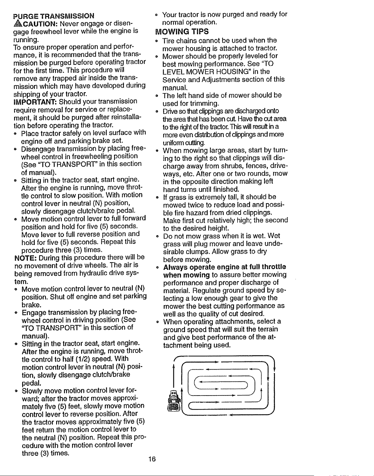
o When mowing large areas, start by turn-
ing to the right so that clippings will dis-
charge away from shrubs, fences, drive-
ways, etc. After one or two rounds, mow
in the opposite direction making left
hand turns until finished.
• If grass is extremely tall, it should be
mowed twice to reduce load and possi-
ble fire hazard from dried clippings.
Make first cut relatively high; the second
to the desired height.
o Do not mow grass when it is weL Wet
grass wilt plug mower and leave unde-
sirable clumps° Allow grass to dry
before mowing.
o Always operate engine at full throttle
when mowing to assure better mowing
performance and proper discharge of
material. Regulate ground speed by se-
lecting a low enough gear to give the
mower the best cutting performance as
well as the quality of cut desired.
= When operating attachments, select a
ground speed that will suit the terrain
and give best performance of the at-
tachment being used.
f
1
16
MULCHING MOWING TIPS
IMPORTANT: For best performance, keep
mower housing free of built-up grass and
trash. Clean after each use.
o The special mulching blade will recut
_the grass clippings many times and
reduce them in size so that as they fall
onto the lawn they will disperse into the
grass and not be noticed. Also, the
mulched grass will biodegrade quickly
to provide nutrients for the lawn. Always
mulch with your highest engine (blade)
speed as this will provide the best recut-
ting action of the blades.
,, Avoid cutting your lawn when it is wet.
Wet grass tends to form clumps and
interferes with the mulching action. The
best time to mow your lawn is the early
afternoon. At this time the grass has
dried and the newly cut area will not be
exposed to the direct sun.
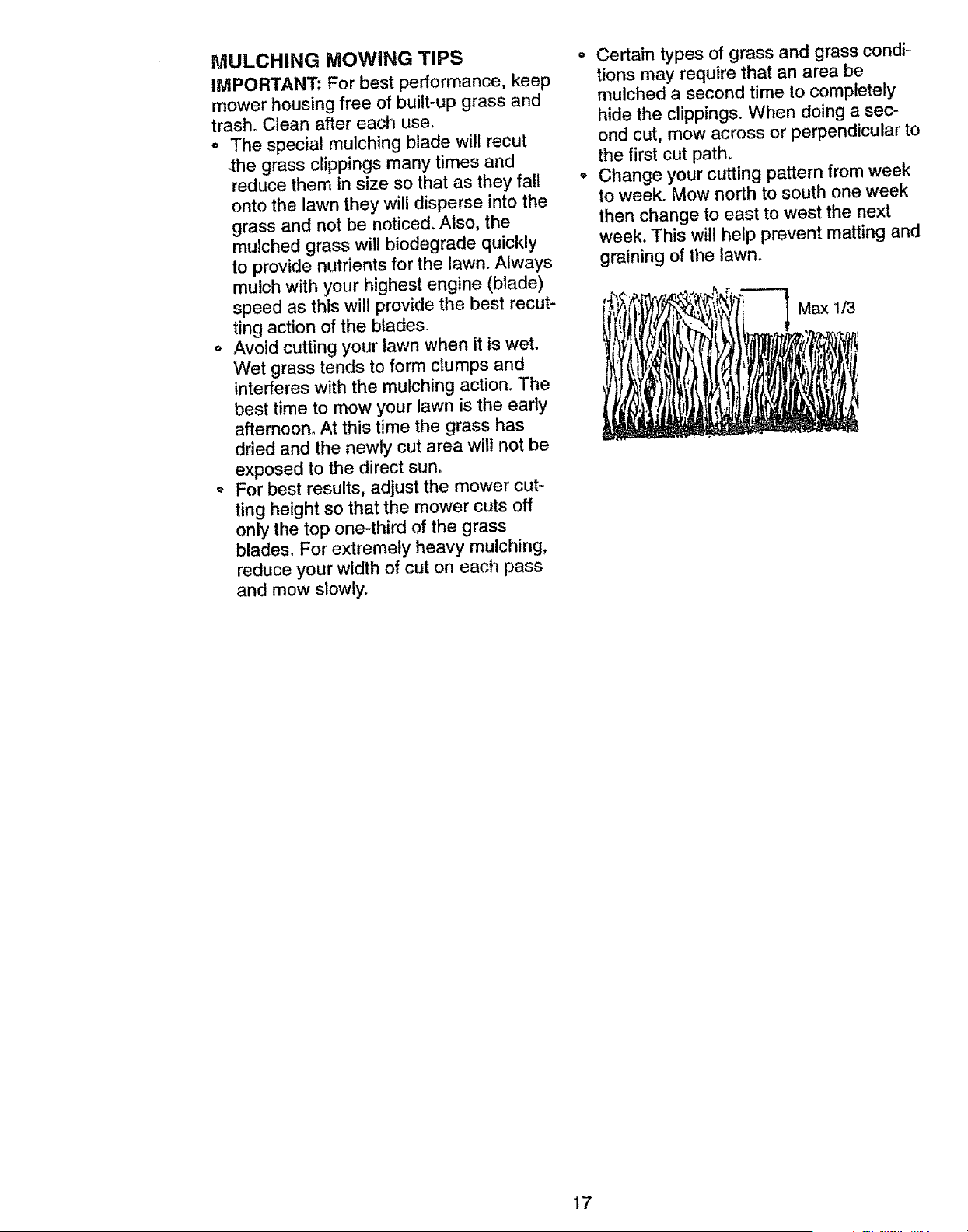
° For best results, adjust the mower cut,..
ting height so that the mower cuts off
only the top one-third of the grass
blades. For extremely heavy mulching,
reduce your width of cut on each pass
and mow slowly.
° Certain types of grass and grass condi-
tions may require that an area be
mulched a second time to completely
hide the clippings. When doing a sec-
ond cut, mow across or perpendicular to
the first cut path.
• Change your cutting pattern from week
to week. Mow north to south one week
then change to east to west the next
week. This will help prevent matting and
graining of the lawn.
Maxl_
17
ENGINE
CUSTOMER RESPONSIBILITIES
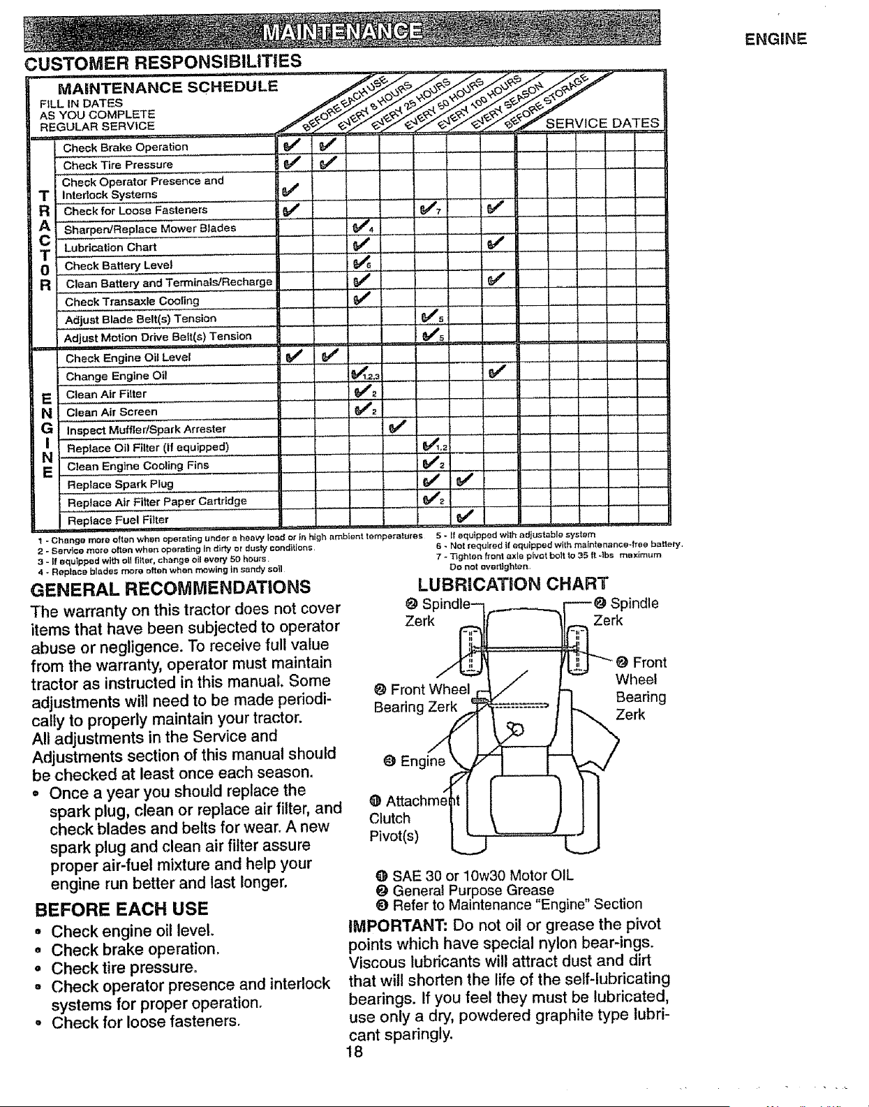
MAINTENANCE SCHEDULE
FtLL IN DATES
AS YOU COMPLETE
REGULAR SERVICE
Check Brake Operation
Check Tire Pressure
Check Operator Presence and ......
T Interlock Systems
R Check for Loose 'F'_steners
cA Sharpen!Repia'ce'"M'ower Blades
T Lubrication Chart
O Check Battery Level
a C!ean Battery and Ten'nin,_ls/R,echarge
Chec k Transaxle Cooling ............
Adjust Blade Belt(s) Tension
' Adjust Motion DriVe Belt(s) Tension
Check Engine Oil Level I _ 6##
Change Engine Oil
Clean Air Filter
" C ean A{r Screen .........................................
G ,nspo=Mu.le_Spa;"Arre;te,.............
Replace Oil Filter (if equipped)
Replace Spark Plug
Replace Air Fif_er Paper Cartridge
Replace Fuel Filter
SERVICE DATES
le,, _,
_ex
v',
v' v'o , , , ,
• i ,, ,,
I
_5
, _1,2!
e,'2
v"
1 - Change rno[e often when operating under a heavy load or in high ambient temperatures 5 - ff equipped with adjustable system
2 - Service more often when operating in dirty or dusty conditions,
3 - _!equipped with ot__tet, change oll every 50 hours
4 - Rep_ce blsdes mere often when mowing In sandy soll
GENERAL RECOMMENDATIONS
The warranty on this tractor does not cover
items that have been subjected to operator
abuse or negligence. To receive full value
from the warranty, operator must maintain
tractor as instructed in this manual. Some
adjustments will need to be made periodi-
cally to properly maintain your tractor.
All adjustments in the Service and
Adjustments section of this manual should
be checked at least once each season.
• Once a year you should replace the
spark plug, clean or replace air filter, and
check blades and belts for wear. A new
spark plug and clean air filter assure
proper air-fuel mixture and help your
engine run better and last longer.
BEFORE EACH USE
= Check engine oil level
o Check brake operation,
° Check tire pressure,
° Check operator presence and interlock
systems for proper operation,
° Check for loose fasteners,
6 - Not required If equipped with maintenance-free ba_.ely,
7 - Tighten front axle plv_t bolt to 35 ft -Ibs max}mum
Do not over!}ghten
LUBRICATION CHART
Spindle-- ._____.._. _ Spindle
Zerk
O Front Wheel,
Bearing _
O Engine_
@ Attachment I
cJutch I I
Pivot(s) L_.__L
rk
Front
Wheel
f Bearing
Zerk
@ SAE 30 or 10w30 Motor OIL
General Purpose Grease
_) Refer to Maintenance Engine" Section
IMPORTANT: Do not oil or grease the pivot
points which have special nylon bear-ings.
Viscous lubricants will attract dust and dirt
that will shorten the life of the self-lubricating
bearings. If you feel they must be lubricated,
use only a dry, powdered graphite type lubri-
cant sparingly.
18
TRACTOR
Always observe safety rules when per-
forming any maintenance.
BRAKE OPERATION
if tractor requires more than six (6) feet
stopping distance at high speed in highest
gear, then brake must be adjusted.(See
'%0 ADJUST BRAKE" in the Service and
Adjustments section of this manual).
TIRES
o Maintain proper air pressure in all tires
(See "PRODUCT SPECIFICATIONS"
on page 5 of this manual).
o Keep tires free of gasoline, oil, or insect
control chemicals which can harm rub-
ber.
o Avoid stumps, stones, deep ruts, sharp
objects and other hazards that may
cause tire damage.
NOTE" To seal tire punctures and prevent
flat tires due to slow leaks, tire sealant
may be purchased from your local parts
dealer. Tire sealant also prevents tire dry
rot and corrosion.
BLADE CARE
For best results mower blades must be
kept sharp. Replace bent or damaged
blades.
BLADE REMOVAL
o Raise mower to highest position to allow
access to blades.
o Remove hex bolt, lock washer and flat
washer securing blade.
o Install new or resharpened blade with
trailing edge up towards deck as shown.
IMPORTANT: To ensure proper assembly,
center hole in blade must align with star
on mandrel assembly.
o Reassemble hex bolt, lock washer and
flat washer in exact order as shown°
o Tighten bolt securely (30-35 Ft. Lbs.
torque).
IMPORTANT: Blade bolt is Grade 8 heat
treated. Mandrel
Trailing Blade Assembly
Edge Up_ \ Center f_,_
LockWasher, "_" _ "-'_-_' \ _" r
*A Grade 8 heat treated bolt can be
identified by six lines on the bolt head.
TO SHARPEN BLADE
NOTE: We do not recommend sharpening
blade, but if you do, be sure the blade is
balanced.
Care should be taken to keep the blade
balanced. An unbalanced blade will cause
excessive vibration and eventual damage
to mower and engine.
o The blade can be sharpened with a file
or on a grinding wheel. Do not attempt
to sharpen while it is on the mower.
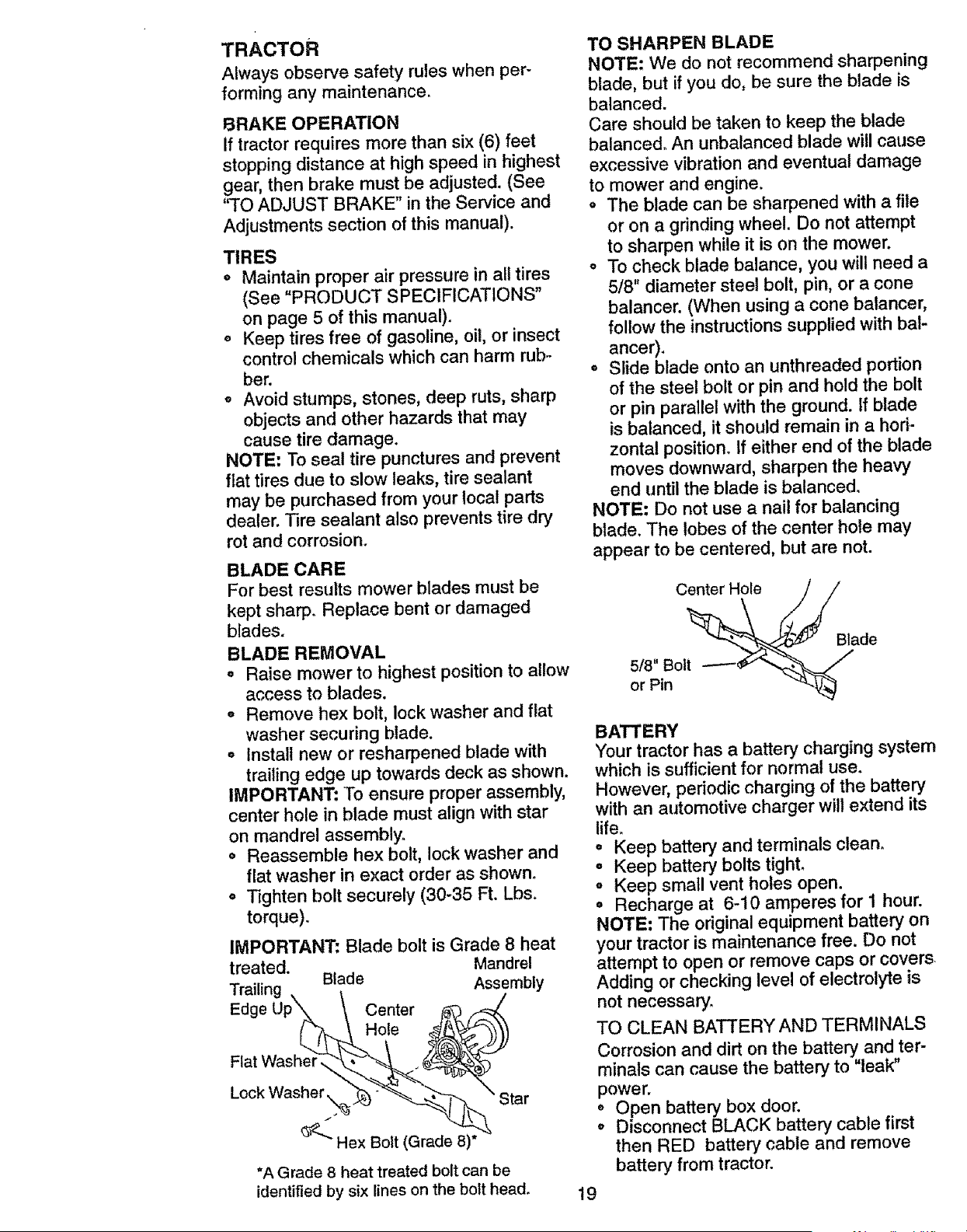
o To check blade balance, you will need a
5/8" diameter steel bolt, pin, or a cone
balancer. (When using a cone balancer,
follow the instructions supplied with bal-
ancer).
o Slide blade onto an unthreaded portion
of the steel bolt or pin and hold the bolt
or pin parallel with the ground. If blade
is balanced, it should remain in a hori-
zontal position° If either end of the blade
moves downward, sharpen the heavy
end until the blade is balanced.
NOTE: Do not use a nail for balancing
blade. The lobes of the center hole may
appear to be centered, but are not.
Center Hole
5/8" Bolt
or Pin
Blade
BATTERY
Your tractor has a battery charging system
which is sufficient for normal use.
However, periodic charging of the battery
with an automotive charger will extend its
life.
o Keep battery and terminals clean.
o Keep battery bolts tight.
o Keep small vent holes open.
o Recharge at 6-10 amperes for 1 hour.
NOTE: The original equipment battery on
your tractor is maintenance free. Do not
attempt to open or remove caps or covers
Adding or checking level of electrolyte is
not necessary.
TO CLEAN BATTERY AND TERMINALS
Corrosion and dirt on the battery and ter-
minals can cause the battery to "leak"
power.
o Open battery box door.
o Disconnect BLACK battery cable first
then RED battery cable and remove
battery from tractor.
19
o Rinse the battery with plain water and
dry.
° Clean terminals and battery cableends
with wire brush until bright.
° Coat terminals with grease or petroleum
jelly.
° Reinstallbattery (See "REPLACING
BATTERY"in the SERVICEAND
ADJUSTMENTSsection of this
manual).
V-BELTS
Check V-belts for deteriorationand wear
after 100 hours of operation and replace if
necessary. The belts are not adjustable.
Replace belts if they begin to slip from
wear.
TRANSAXLE COOLING
The transmission fan and cooling fins
should be kept clean to assure proper
cooling.
Do not attempt to clean fan or transmis-
sion while engine is running or while the
transmission is hot.
o Inspect cooling fan to be sure fan
blades are intact and clean.
• Inspect cooling fins for dirt, grass clip-
pings and other materials. To prevent
damage to seals, do not use com-
pressed air or high pressure sprayer to
clean cooling fins.
TRANSAXLE PUMP FLUID
The transaxle was sealed at the factory
and fluid maintenance is not required for
the life of the transaxle. Should the
transaxle ever leak or require servicing,
contact your nearest authorized service
center.
ENGINE
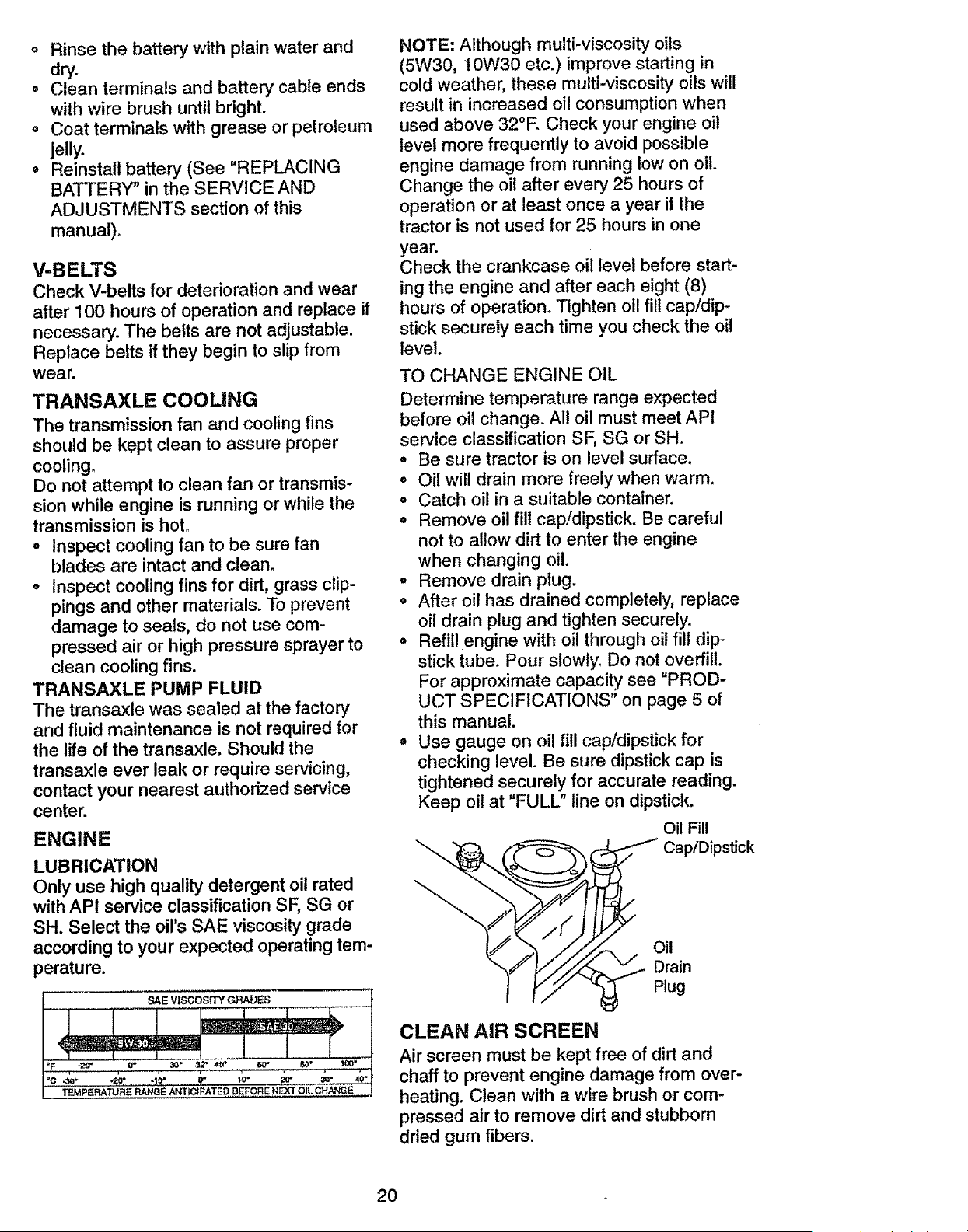
LUBRICATION
Only use high quality detergent oil rated
with API service classification SF, SG or
SH. Select the oil's SAE viscosity grade
according to your expected operating tem-
perature.
NOTE: Although multi-viscosity oils
(5W30, 10W30 etc.) improve starting in
cold weather, these multi-viscosity oils will
result in increased oil consumption when
used above 32°E Check your engine oil
level more frequently to avoid possible
engine damage from running low on oil
Change the oil after every 25 hours of
operation or at least once a year if the
tractor is not used for 25 hours in one
year.
Check the crankcase oil level before start-
ing the engine and after each eight (8)
hours of operation° Tighten oil fill cap/dip-
stick securely each time you check the oil
level.
TO CHANGE ENGINE OIL
Determine temperature range expected
before oil change. All oil must meet API
service classification SF, SG or SH.
• Be sure tractor is on level surface.
o Oil will drain more freely when warm.
• Catch oil in a suitable container.
• Remove oil fill cap!dipstick. Be careful
not to allow dirt to enter the engine
when changing oil.
° Remove drain plug.
• After oil has drained completely, replace
oil drain plug and tighten securely.
• Refill engine with oil through oil fill dip-
stick tube. Pour slowly_ Do not overfill.
For approximate capacity see "PROD-
UCT SPECIFICATIONS" on page 5 of
this manual.
• Use gauge on oil fill cap/dipstick for
checking level. Be sure dipstick cap is
tightened securely for accurate reading.
Keep oil at "FULL" line on dipstick.
Oil Fill
__ Cap/Dipstick
/.
.o,
""_! _"yy/<_._ Drain
I t'Y ,ug
CLEAN AIR SCREEN
Air screen must be kept free of dirt and
chaff to prevent engine damage from over-
heating. Clean with a wire brush or com-
pressed air to remove dirt and stubborn
dried gum fibers.
2O
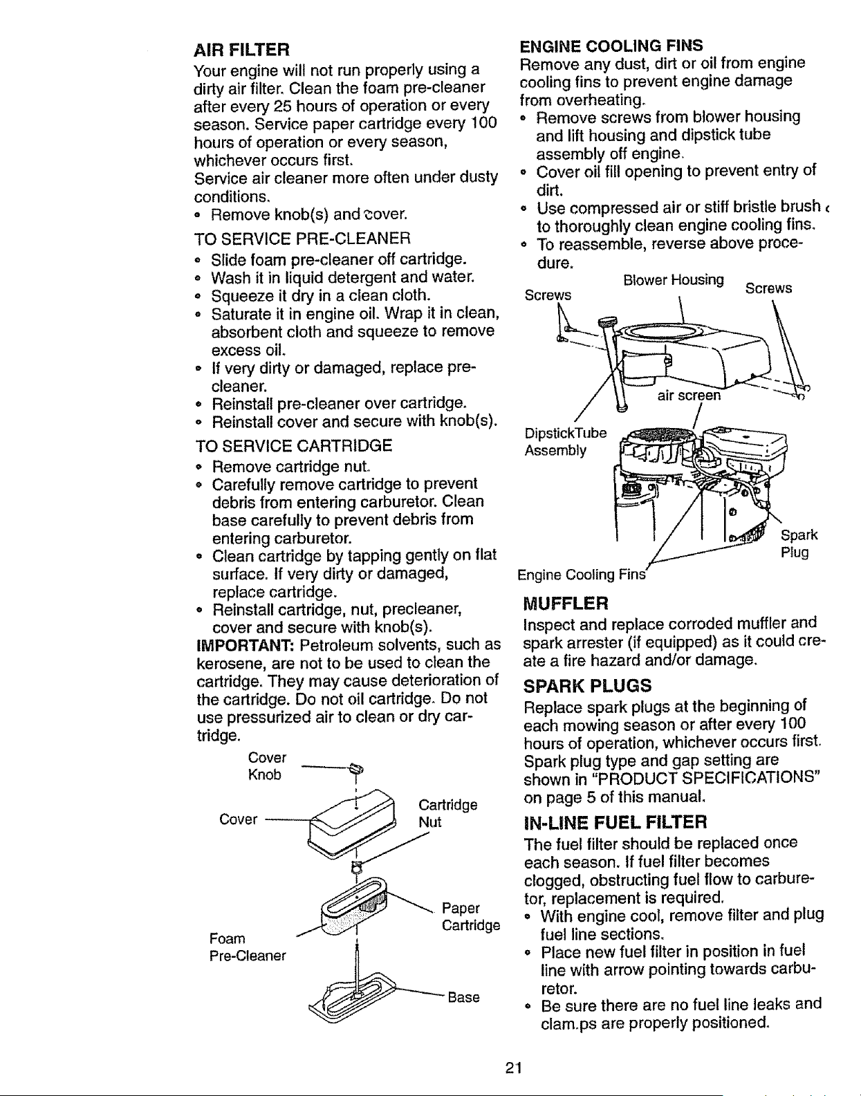
AIR FILTER
Your engine will not run propedy using a
dirty air filter. Clean the foam pre-cleaner
after every 25 hours of operation or every
season_ Service paper cartridge every 100
hours of operation or every season,
whichever occurs first.
Service air cleaner more often under dusty
conditions.
o Remove knob(s) and _over.
TO SERVICE PRE-CLEANER
° Slide foam pre-cleaner off cartridge.
= Wash it in liquid detergent and water.
o Squeeze it dry in a clean cloth.
• Saturate it in engine oil. Wrap it in clean,
absorbent cloth and squeeze to remove
excess oil
o If very dirty or damaged, replace pre-
cleaner.
° Reinstall pre-cleaner over cartridge°
o Reinstall cover and secure with knob(s).
TO SERVICE CARTRIDGE
o Remove cartridge nut.
o Carefully remove cartridge to prevent
debris from entering carburetor. Clean
base carefully to prevent debris from
entering carburetor.
o Clean cartridge by tapping gently on flat
surface° If very dirty or damaged,
replace cartridge.
° Reinstall cartridge, nut, precleaner,
cover and secure with knob(s).
IMPORTANT; Petroleum solvents, such as
kerosene, are not to be used to clean the
cartridge. They may cause deterioration of
the cartridge. Do not oil cartridge. Do not
use pressurized air to clean or dry car-
tridge.
Cover
Knob -'-'---'_
Cover _ Cartridge
Foam
Pre-Cleaner
Paper
Ca_ddge
_-Base
ENGINE COOLING FINS
Remove any dust, dirt or oil from engine
cooling fins to prevent engine damage
from overheating.
o Remove screws from blower housing
and lift housing and dipstick tube
assembly off engine,
o Cover oil fill opening to prevent entry of
dirt.
= Use compressed air or stiff bristle brush €
to thoroughly clean engine cooling fins.
° To reassemble, reverse above proce-
dure.
Screws Blower Housing Screws
air screen
DipstickTube
Assembly
Engine Cooling
MUFFLER
Inspect and replace corroded muffler and
spark arrester (if equipped) as it could cre-
ate a fire hazard and/or damage.
SPARK PLUGS
Replace spark plugs at the beginning of
each mowing season or after every 100
hours of operation, whichever occurs first.
Spark plug type and gap setting are
shown in "PRODUCT SPECIFICATIONS"
on page 5 of this manual
IN-LINE FUEL FILTER
The fuel filter should be replaced once
each season. If fuel filter becomes
clogged, obstructing fuel flow to carbure-
tor, replacement is required,
° With engine cool, remove filter and plug
fuel line sections.
° Place new fuel filter in position in fuel
line with arrow pointing towards carbu-
retor.
° Be sure there are no fuel line leaks and
clam.ps are properly positioned.
21
Filter
3LEANING
Clean engine, battery, seat, finish, etc.
of all foreign matter.
o Keep finished surfaces and wheels free
of all gasoline, oil, etc.
o Protect painted surfaces with automo-
tive type wax.
We do not recommend using a garden
hose to clean your tractor unless the elec-
trical system, muffler, air filter and carbure-
tor are covered to keep water out. Water
in engine can result in a shortened engine
life.
_,CAUTION: Before performing any service or adjustments:
• Depress clutch/brake pedal fully and set parking brake.
° Place motion control lever in neutral (N) position.
• Place attachment clutch in "DISENGAGED" position.
o Turn ignition key "OFF" and remove key.
° Make sure the blades and all moving parts have completely stopped.
• Disconnect spark plug wire from spark plug and place wire where it cannot come
in contact with plug.
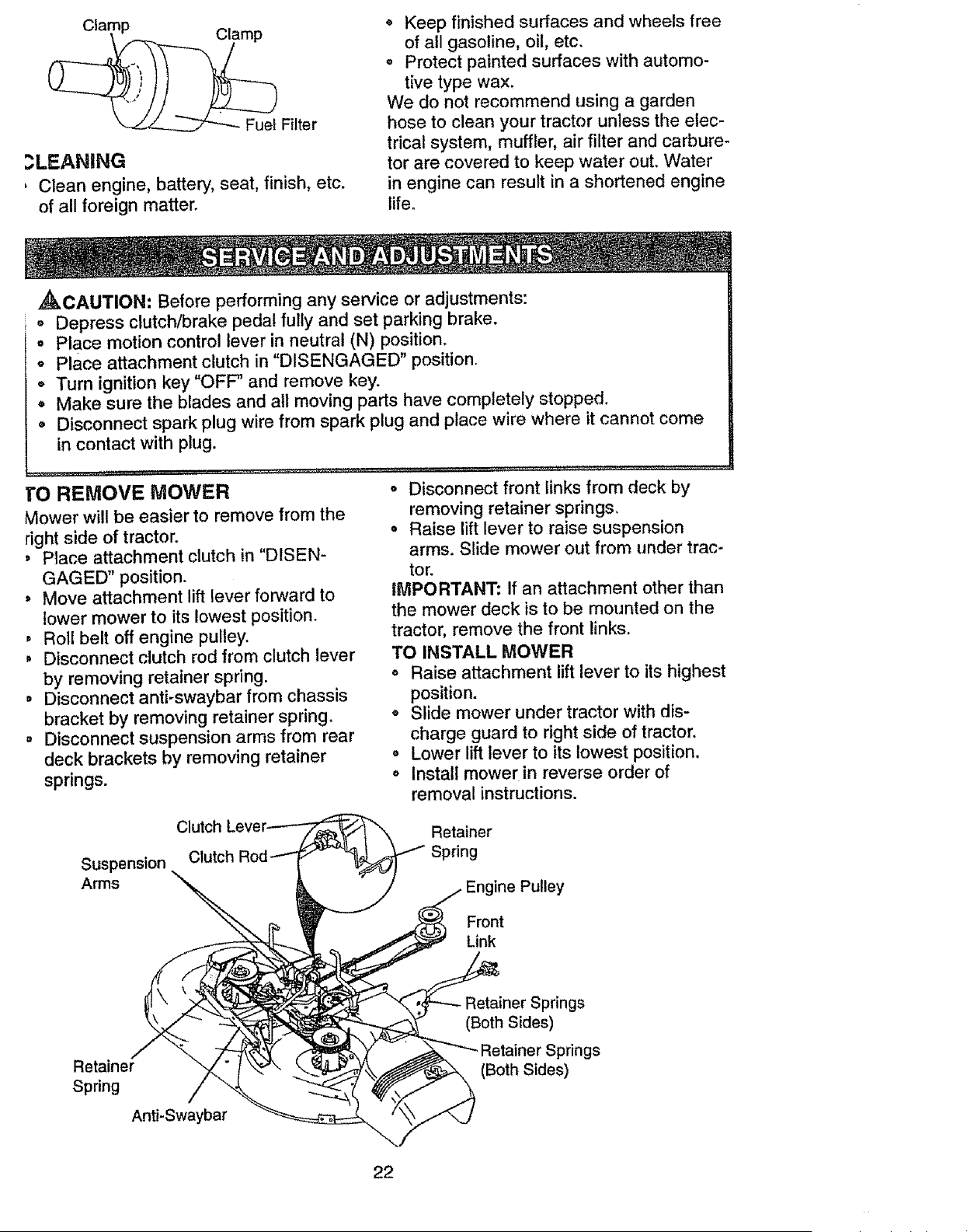
TO REMOVE MOWER
Mower will be easier to remove from the
right side of tractor.
, Place attachment clutch in "DISEN-
GAGED" position.
, Move attachment lift lever forward to
lower mower to its lowest position.
, Roll belt off engine pulley.
, Disconnect clutch rod from clutch lever
by removing retainer spring.
= Disconnect anti-swaybar from chassis
bracket by removing retainer spring.
= Disconnect suspension arms from rear
deck brackets by removing retainer
springs.
° Disconnect front links from deck by
removing retainer spdngs.
° Raise lift lever to raise suspension
arms. Slide mower out from under trac-
tor.
IMPORTANT: If an attachment other than
the mower deck is to be mounted on the
tractor, remove the front links.
TO INSTALL MOWER
° Raise attachment lift lever to its highest
position.
o Slide mower under tractor with dis-
charge guard to right side of tractor.
, Lower lift lever to its lowest position.
o Install mower in reverse order of
removal instructions.
Suspension Clutch
Arms
Retainer
Spring
ine Pulley
Front
Link
Retainer
Spring
Anti-Swaybar
Retainer Springs
(Both Sides)
,r Springs
(Both Sides)
22
TO LEVEL MOWER HOUSING
Adjust the mower while tractor is parked
on level ground or driveway. Make sure
tires are properly inflated (See "PROD-
UCT SPECIFICATIONS"). tf tires are
over or underinflated, you will not properly
adjust your mower°
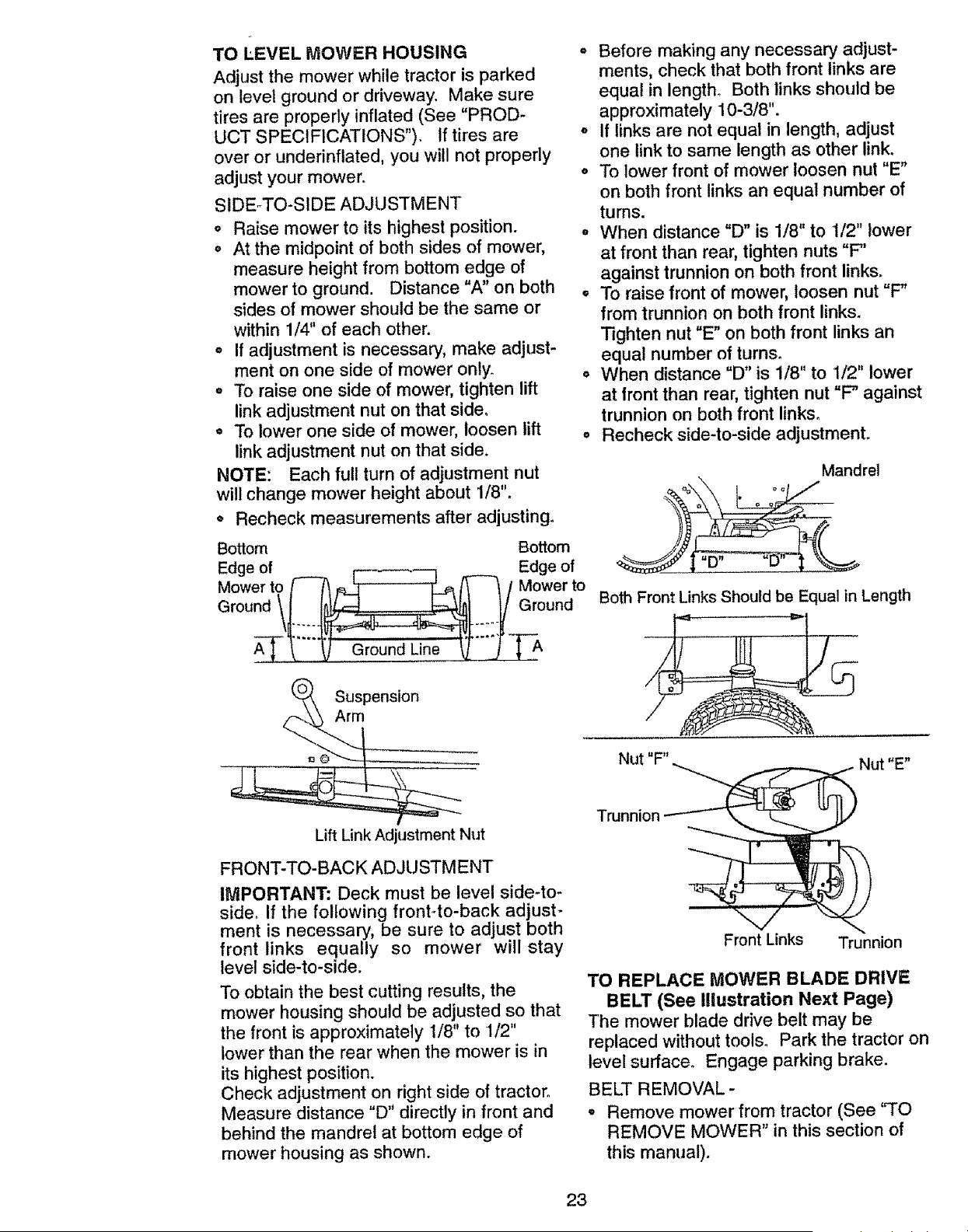
SIDE-TO-SIDE ADJUSTMENT
• Raise mower to its highest position.
° At the midpoint of both sides of mower,
measure height from bottom edge of
mower to ground. Distance "A" on both
sides of mower should be the same or
within 1/4" of each other.
° If adjustment is necessary, make adjust-
ment on one side of mower only.
, To raise one side of mower, tighten lift
link adjustment nut on that side.
. To lower one side of mower, loosen lift
link adjustment nut on that side.
NOTE: Each full turn of adjustment nut
will change mower height about 1/8".
° Recheck measurements after adjusting°
Bottom
Edge of
Mower to _ ,_ _[_'-'-"-'_l a/_-'-q, I
ar°und/l
"_-"_J Ground Line _-'TJ-
Suspension
Arm
Bottom
Edge of
Mower to
Ground
Lift Link Adjustment Nut
FRONT-TO-BACK ADJUSTMENT
IMPORTANT: Deck must be level side-to-
side, If the following front.-to-back adjust-
ment is necessary, be sure to adjust both
front links equally so mower will stay
level side-to-side.
To obtain the best cutting results, the
mower housing should be adjusted so that
the front is approximately 1/8" to 1/2"
lower than the rear when the mower is in
its highest position.
Check adjustment on right side of tractor°
Measure distance "D" directly in front and
behind the mandrel at bottom edge of
mower housing as shown.
o Before making any necessary adjust-
ments, check that both front links are
equal in length° Both links should be
approximately 10-3/8".
, If links are not equal in length, adjust
one link to same length as other link.
° To lower front of mower loosen nut "E"
on both front links an equal number of
turns.
° When distance "D" is 1/8" to 1/2" lower
at front than rear, tighten nuts "F"
against trunnion on both front link&
, To raise front of mower, loosen nut =F"
from trunnion on both front links.
Tighten nut =E" on both front links an
equal number of turns.
, When distance =D" is 1/8" to 1/2" lower
at front than rear, tighten nut "F" against
trunnion on both front link&
. Recheck side-to-side adjustment.
Mandrel
"13"
Both Front Links Should be Equal in Length
N u _
ut F _ Nut "E"
Trunnion ___
Front Links Trunnion
TO REPLACE MOWER BLADE DRIVE
BELT (See Illustration Next Page)
The mower blade drive belt may be
replaced without tools, Park the tractor on
level surface. Engage parking brake.
BELT REMOVAL-
o Remove mower from tractor (See "TO
REMOVE MOWER" in this section of
this manual).
23
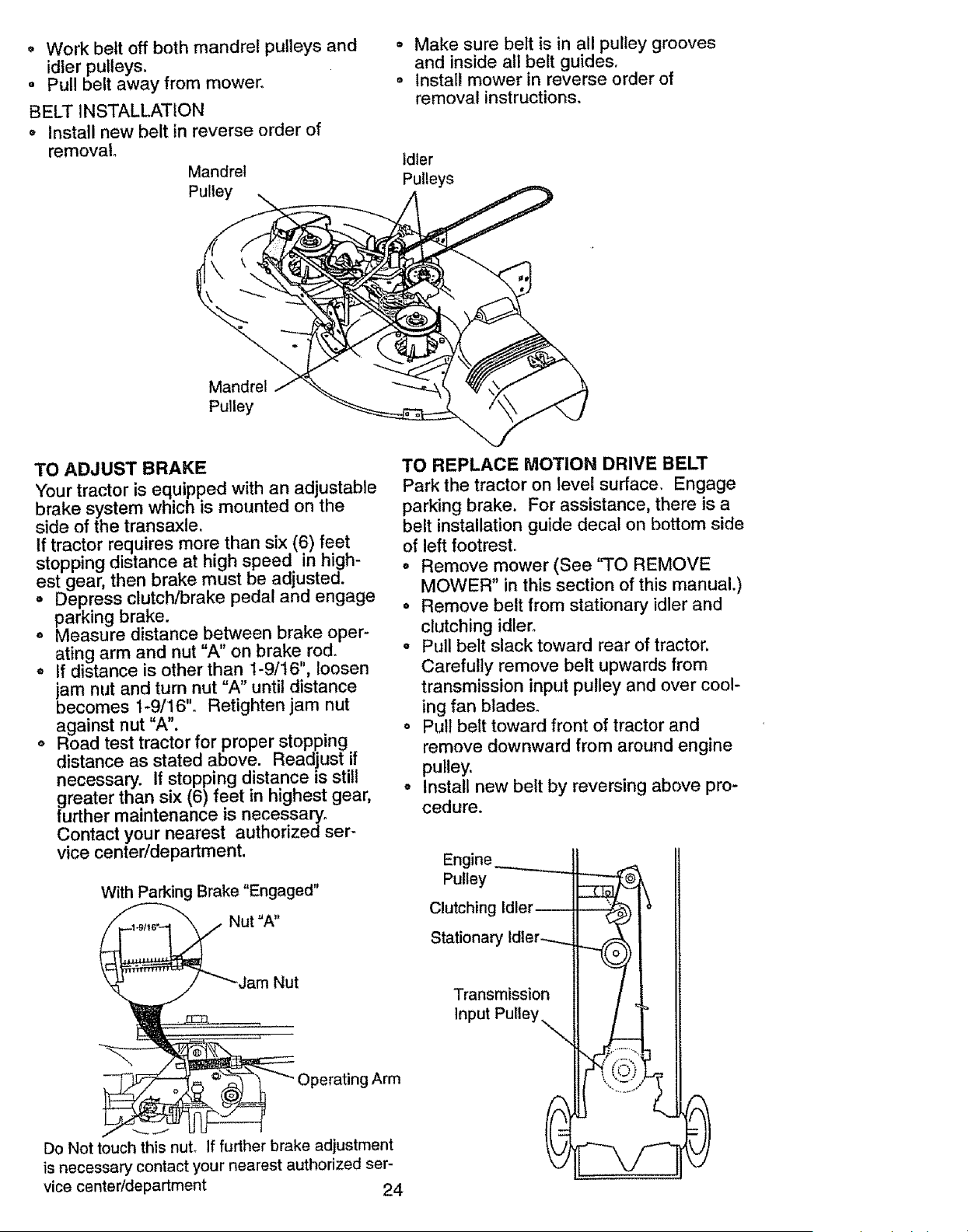
o Work belt off both mandrel pulleys and
idler pulleys.
° Pull belt away from mowen
BELTINSTALLATION
o Install new belt in reverse order of
removal
Mandrel
Pulley
o Make sure belt is in all pulley grooves
and inside all belt guides.
o Install mower in reverse order of
removalinstructions.
Idler
Pulleys
Mandrel
Pulley
TO ADJUST BRAKE
Your tractor is equipped with an adjustable
brake system which is mounted on the
side of the transaxle.
If tractor requires more than six (6) feet
stopping distance at high speed in high-
est gear, then brake must be adjusted.
o Depress clutch/brake pedal and engage
parking brake.
o Measure distance between brake oper-
ating arm and nut "A" on brake rod.
o If distance is other than 1-9/16", loosen
jam nut and turn nut "A" until distance
becomes 1-9/16". Retighten jam nut
against nut "A".
o Road test tractor for proper stopping
distance as stated above. Readjust if
necessary, if stopping distance is still
greater than six (6)feet in highest gear,
further maintenance is necessary.
Contact your nearest authorized ser-
vice center/department.
With Parking Brake "Engaged"
Nut
Operating Arm
Do Not touch this nuL If further brake adjustment
is necessary contact your nearest authorized ser-
vice center/department 24
TO REPLACE MOTION DRIVE BELT
Park the tractor on level surface. Engage
parking brake. For assistance, there is a
belt installation guide decal on bottom side
of left footrest.
• Remove mower (See 'qO REMOVE
MOWER" in this section of this manual.)
o Remove belt from stationary idler and
clutching idler.
° Pull belt slack toward rear of tractor.
Carefully remove belt upwards from
transmission input pulley and over cool-
ing fan blades.
° Pull belt toward front of tractor and
remove downward from around engine
pulley.
o Install new belt by reversing above pro-
cedure.
Engine II ._
Pulley
Clutching 'dler_ i '
Transmission 11 / &
Input
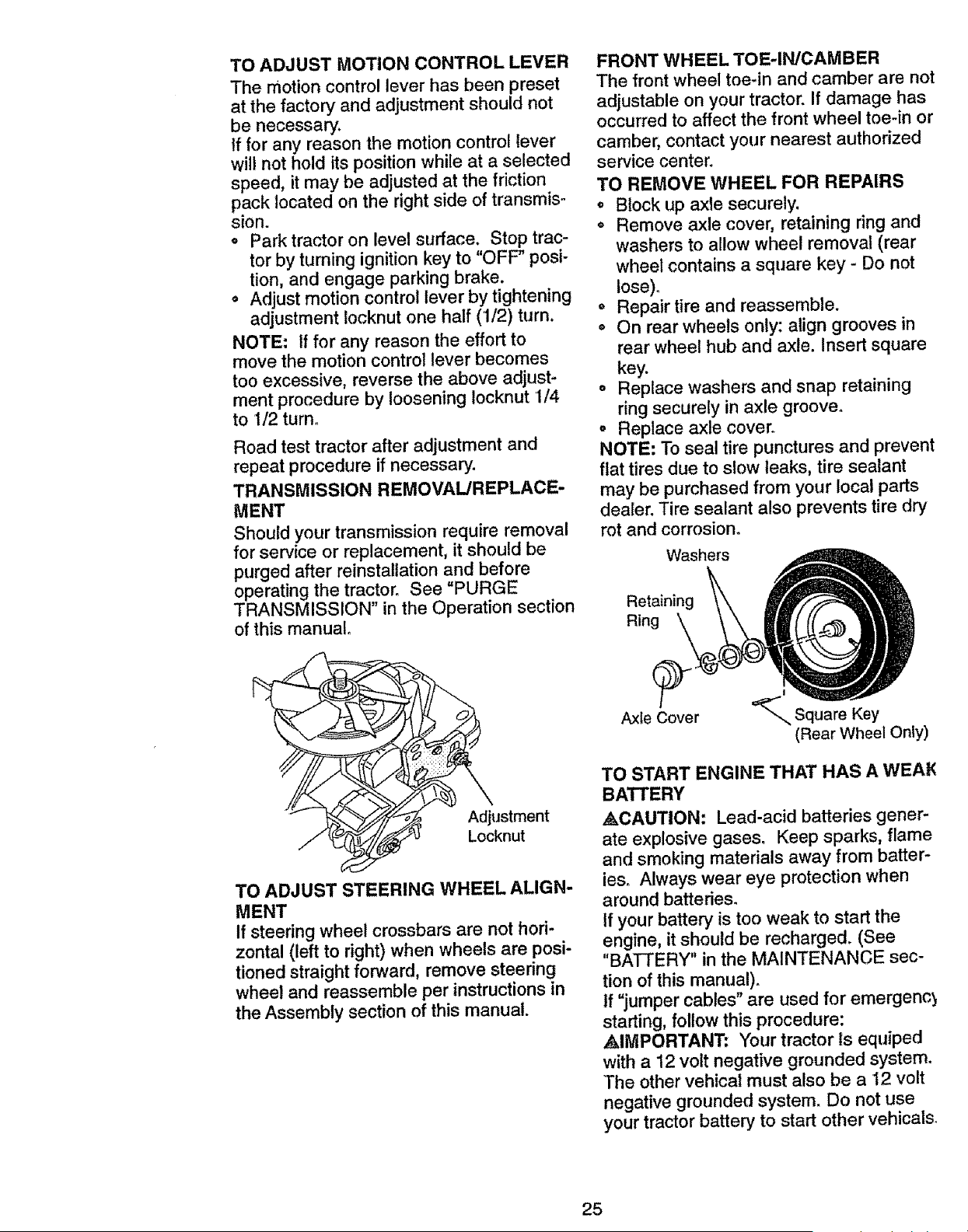
TO ADJUST MOTION CONTROL LEVER
The motion control lever has been preset
at the factory and adjustment should not
be necessary.
If for any reason the motion control lever
will not hold its position while at a selected
speed, it may be adjusted at the friction
pack located on the right side of transmis-
sion.
o Park tractor on level surface. Stop trac-
tor by turning ignition key to "OFF" posi-
tion, and engage parking brake.
° Adjust motion control lever by tightening
adjustment Iocknut one half (1/2) turn.
NOTE= If for any reason the effort to
move the motion control lever becomes
too excessive, reverse the above adjust-
ment procedure by loosening Iocknut 1/4
to 1/2 turn.
Road test tractor after adjustment and
repeat procedure if necessary.
TRANSMISSION REMOVAL/REPLACE-
MENT
Should your transmission require removal
for service or replacement, it should be
purged after reinstallation and before
operating the tractor. See =PURGE
TRANSMISSION" in the Operation section
of this manual°
FRONT WHEEL TOE-IN/CAMBER
The front wheel toe-in and camber are not
adjustable on your tractor. If damage has
occurred to affect the front wheel toe-in or
camber, contact your nearest authorized
service center.
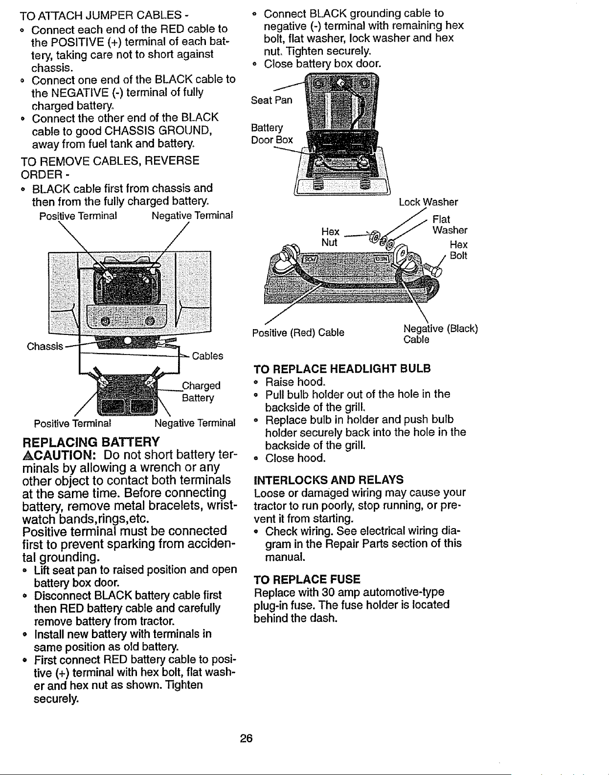
TO REMOVE WHEEL FOR REPAIRS
° Block up axle securely.
o Remove axle cover, retaining ring and
washers to allow wheel removal (rear
wheel contains a square key - Do not
iose)o
o Repair tire and reassemble.
o On rear wheels only: align grooves in
rear wheel hub and axle. Insert square
key.
o Replace washers and snap retaining
ring securely in axle groove.
° Replace axle cover.
NOTE: To seal tire punctures and prevent
flat tires due to slow leaks, tire sealant
may be purchased from your local parts
dealer. Tire sealant also prevents tire dry
rot and corrosion°
Washers
Retaining
Ring
Adjustment
Locknut
TO ADJUST STEERING WHEEL ALIGN-
MENT
If steering wheel crossbars are not hori-
zontal (left to right) when wheels are posi-
tioned straight forward, remove steering
wheel and reassemble per instructions in
the Assembly section of this manual.
Axle Cover
I
=_-,,. Square Key
(Rear Wheel Only)
TO START ENGINE THAT HAS A WEAK
BATTERY
ACAUTION: Lead-acid batteries gener-
ate explosive gases° Keep sparks, flame
and smoking materials away from batter-
ies_ Always wear eye protection when
around batteries.
If your battery is too weak to start the
engine, it should be recharged. (See
"BATTERY" in the MAINTENANCE sec-
tion of this manual).
If "jumper cables" are used for emergenc_
starting, follow this procedure:
AIMPORTANT: Your tractor Is equiped
with a 12 volt negative grounded system.
The other vehica| must also be a 12 volt
negative grounded system_ Do not use
your tractor battery to start other vehicals.
25
TO A'FFACH JUMPER CABLES -
o Connect each end of the RED cable to
the POSITIVE (+) terminal of each bat-
tery, taking care not to short against
chassis.
o Connect one end of the BLACK cable to
the NEGATIVE (-) terminal of fully
charged battery°
• Connect the other end of the BLACK
cable to good CHASSIS GROUND,
away from fuel tank and battery,
TO REMOVE CABLES, REVERSE
ORDER -
• BLACK cable first from chassis and
then from the fully charged battery,
Positive Terminal Negative Terminal
° Connect BLACK grounding cable to
negative (-) terminal with remaining hex
bolt, flat washer, lock washer and hex
nut. Tighten securely.
o Close battery box door.
Seat Pan
Battery
Door Box
LeckWasher
Flat
Hex Washer
Nut Hex
Belt
Positive (Red) Cable
Negative (Black)
Cable
Charged
Battery
Positive Terminal
Negative Terminal
REPLACING BATTERY
,&CAUTION: Do not short battery ter-
minals by allowing a wrench or any
other object to contact both terminals
at the same time. Before connecting
battery, remove metal bracelets, wrist-
watch bands, rings,etc.
Positive terminal must be connected
first to prevent sparking from acciden-
tal grounding.
° Lift seat pan to raised position and open
battery box door.
• Disconnect BLACK battery cable first
then RED battery cable and carefully
remove battery from tractor.
o Install new battery with terminals in
same position as old battery.
° First connect RED battery cable to posi-
tive (+) terminal with hex bolt, flat wash-
er and hex nut as shown. Tighten
securely.
TO REPLACE HEADLIGHT BULB
o Raise hood.
o Pull bulb holder out of the hole in the
backside of the grill°
• Replace bulb in holder and push bulb
holder securely back into the hole in the
backside of the grill.
° Close hood.
iNTERLOCKS AND RELAYS
Loose or damaged wiring may cause your
tractor to run poorly, stop running, or pre-
vent it from starting.
= Check wiring. See electrical wiring dia-
gram in the Repair Parts section of this
manual.
TO REPLACE FUSE
Replace with 30 amp automotive-type
plug-in fuse. The fuse holder is located
behind the dash.
26
TO REMOVE HOOD AND GRILL AS-
SEMBLY
o Raise hood.
o Unsnap headlight wire connector.
= Stand in front of tractor° Grasp hood at
sides, tilt toward engine and lift off of
tractor_
• To replace, reverse above procedures.
Hood
Headlight
Wire
Connector
ENGINE
Manintenance, repair, or replacement of
the emission control devices and systems,
which are being done at the customers
expense, may be performed by any non-
road engine repair estyablishment or indi-
vidual. Warranty repairs must be per-
formed by an authorized engine manufac-
turer's service outlet.
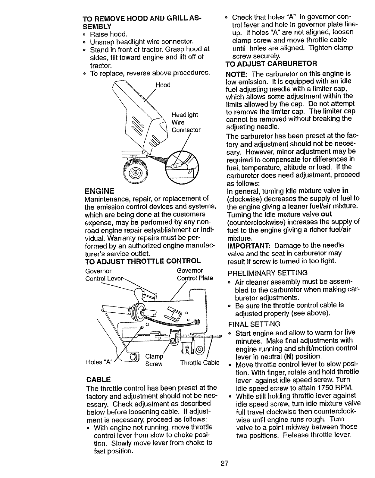
TO ADJUST THROTTLE CONTROL
Governor Governor
Control Control Plate
\
Clamp
Holes "A" Screw Throttle Cable
CABLE
The throttle control has been preset at the
factory and adjustment should not be nec-
essary. Check adjustment as described
below before loosening cable. If adjust-
ment is necessary, proceed as follows:
o With engine not running, move throttle
control lever from slow to choke posi-
tion. Slowly move lever from choke to
fast position.
o Check that holes "A" in governor con_
trol lever and hole in governor plate line-
up. If holes "A" are not aligned, loosen
clamp screw and move throttle cable
until holes are aligned. Tighten clamp
screw securely.
TO ADJUST CARBURETOR
NOTE: The carburetor on this engine is
low emission. It is equipped with an idle
fuel adjusting needle with a limiter cap,
which allows some adjustment within the
limits allowed by the cap. Do not attempt
to remove the limiter cap. The limiter cap
cannot be removed without breaking the
adjusting needle°
The carburetor has been preset at the fac-
tory and adjustment should not be neces-
sary. However, minor adjustment may be
required to compensate for differences in
fuel, temperature, altitude or load. If the
carburetor does need adjustment, proceed
as follows:
tn general, turning idle mixture valve in
(clockwise) decreases the supply of fuel to
the engine giving a leaner fuel/air mixture.
"Fuming the idle mixture valve out
(counterclockwise) increases the supply of
fuel to the engine giving a richer fueValr
mixture.
IMPORTANT: Damage to the needle
valve and the seat in carburetor may
result if screw is turned in too tight.
PRELIMINARY SETTING
= Air cleaner assembly must be assem-
bled to the carburetor when making car-
buretor adjustments.
o Be sure the throttle control cable is
adjusted properly (see above).
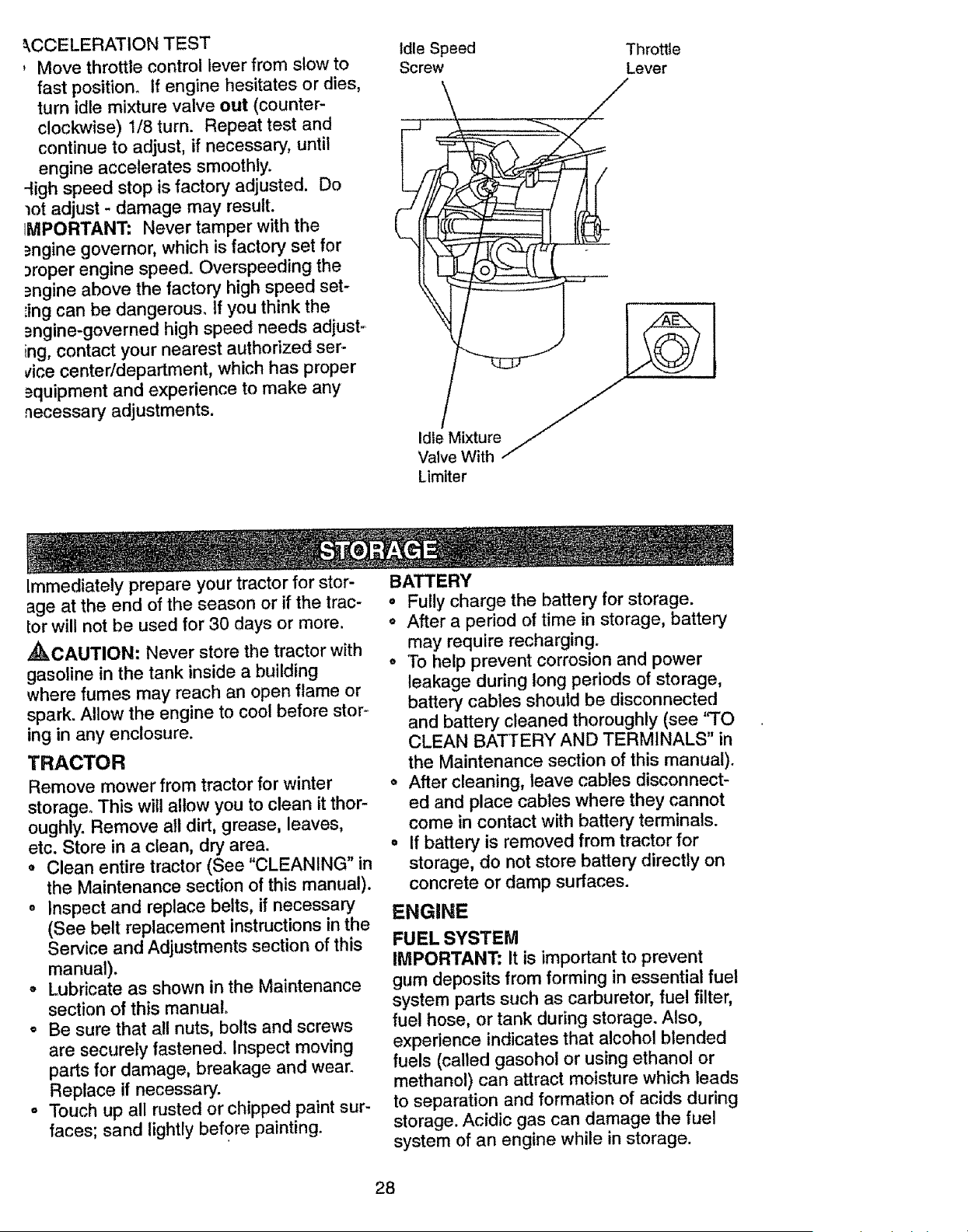
FINAL SETTING
= Start engine and allow to warm for five
minutes. Make final adjustments with
engine running and shift/motion control
lever in neutral (N) position.
° Move throttle control lever to slow posi-
tion. With finger, rotate and hold throttle
lever against idle speed screw. Turn
idle speed screw to attain 1750 RPM.
= While still holding throttle lever against
idle speed screw, turn idle mixture valve
full travel clockwise then counterclock-
wise until engine runs rough. Turn
valve to a point midway between those
two positions. Release throttle lever.
27
_,CCELERATIONTEST
, Move throttle control lever from slow to
fast position, if engine hesitates or dies,
turn idle mixture valve out (counter-
clockwise) 1/8 turn. Repeat test and
continue to adjust, if necessary, until
engine accelerates smoothly.
4igh speed stop is factory adjusted. Do
lot adjust - damage may result.
iMPORTANT: Never tamper with the
_ngine governor, which is factory set for
3roper engine speed. Overspeeding the
)ngine above the factory high speed set-
iing can be dangerous. If you think the
=_ngine-governed high speed needs adjust ._
ing, contact your nearest authorized ser.-
vice center/department, which has proper
_quipment and experience to make any
necessary adjustments.
Idle Speed
Screw
Throttle
Lever
Limiter
Immediately prepare your tractor for stor-
age at the end of the season or if the trac-
tor will not be used for 30 days or more.
,_IkCAUTION: Never store the tractor with
gasoline in the tank inside a building
where fumes may reach an open flame or
spark. Allow the engine to cool before stor..
ing in any enclosure.
TRACTOR
Remove mower from tractor for winter
storage° This will allow you to clean it thor-
oughly. Remove all dirt, grease, leaves,
etc. Store in a clean, dry area.
o Clean entire tractor (See "CLEANING" in
the Maintenance section of this manual).
o Inspect and replace belts, if necessary
(See belt replacement instructions in the
Service and Adjustments section of this
manual).
o Lubricate as shown in the Maintenance
section of this manual.
° Be sure that all nuts, bolts and screws
are securely fastened. Inspect moving
parts for damage, breakage and wear.
Replace if necessary.
o Touch up all rusted or chipped paint sur-
faces; sand lightly before painting.
BATTERY
• Fully charge the battery for storage.
o After a period of time in storage, battery
may require recharging.
° To help prevent corrosion and power
leakage during long periods of storage,
battery cables should be disconnected
and battery cleaned thoroughly (see 'q'O
CLEAN BATTERY AND TERMINALS" in
the Maintenance section of this manual).
• After cleaning, leave cables disconnect-
ed and place cables where they cannot
come in contact with battery terminals.
• If battery is removed from tractor for
storage, do not store battery directly on
concrete or damp surfaces.
ENGINE
FUEL SYSTEM
IMPORTANT: It is important to prevent
gum deposits from forming in essential fuel
system parts such as carburetor, fuel filter,
fuel hose, or tank during storage. Also,
experience indicates that alcohol blended
fuels (called gasohol or using ethanol or
methanol) can attract moisture which leads
to separation and formation of acids during
storage. Acidic gas can damage the fuel
system of an engine while in storage.
28
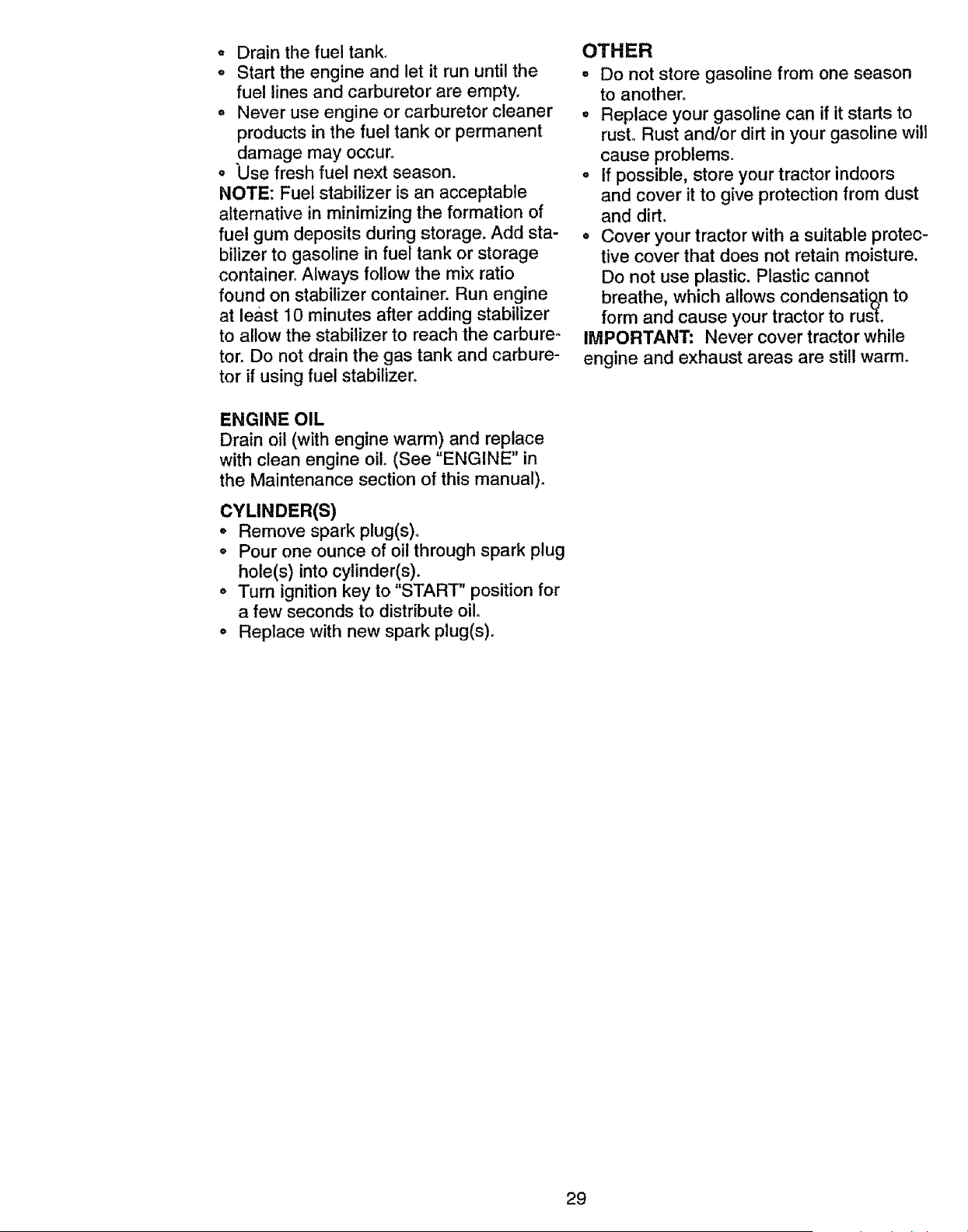
Drain the fuel tank,
o Start the engine and let it run until the
fuel lines and carburetor are empty.
o Never use engine or carburetor cleaner
products in the fuel tank or permanent
damage may occur,.
o Use fresh fuel next season.
NOTE: Fuel stabilizer is an acceptable
alternative in minimizingthe formation of
fuel gum deposits during storage. Add sta-
bilizer to gasoline in fuel tank or storage
container°Always follow the mix ratio
found on stabilizer container.Run engine
at least 10 minutesafter adding stabilizer
to allow the stabilizerto reach the carbure-
tor. Do not drainthe gas tank and carbure-
tor if usingfuel stabilizer.
ENGINE OIL
Drain oil (with enginewarm) and replace
with clean engine oilo(See "ENGINE"in
the Maintenancesection of this manual),
CYLINDER(S)
• Remove spark plug(s)o
o Pour one ounce of oil through spark plug
hole(s) into cylinder(s),
. Turn ignition key to "START" position for
a few seconds to distribute oil.
o Replace with new spark plug(s).
OTHER
• Do not store gasoline from one season
to another_
° Replace your gasoline can if it starts to
rust° Rust and/or dirt in your gasoline will
cause problems.
° If possible, store your tractor indoors
and cover it to give protection from dust
and dirt.
• Cover your tractor with a suitable protec-
tive cover that does not retain moisture.
Do not use plastic, Plastic cannot
breathe, which allows condensatioon to
form and cause your tractor to rust.
IMPORTANT: Never cover tractor while
engine and exhaust areas are still warm°
29
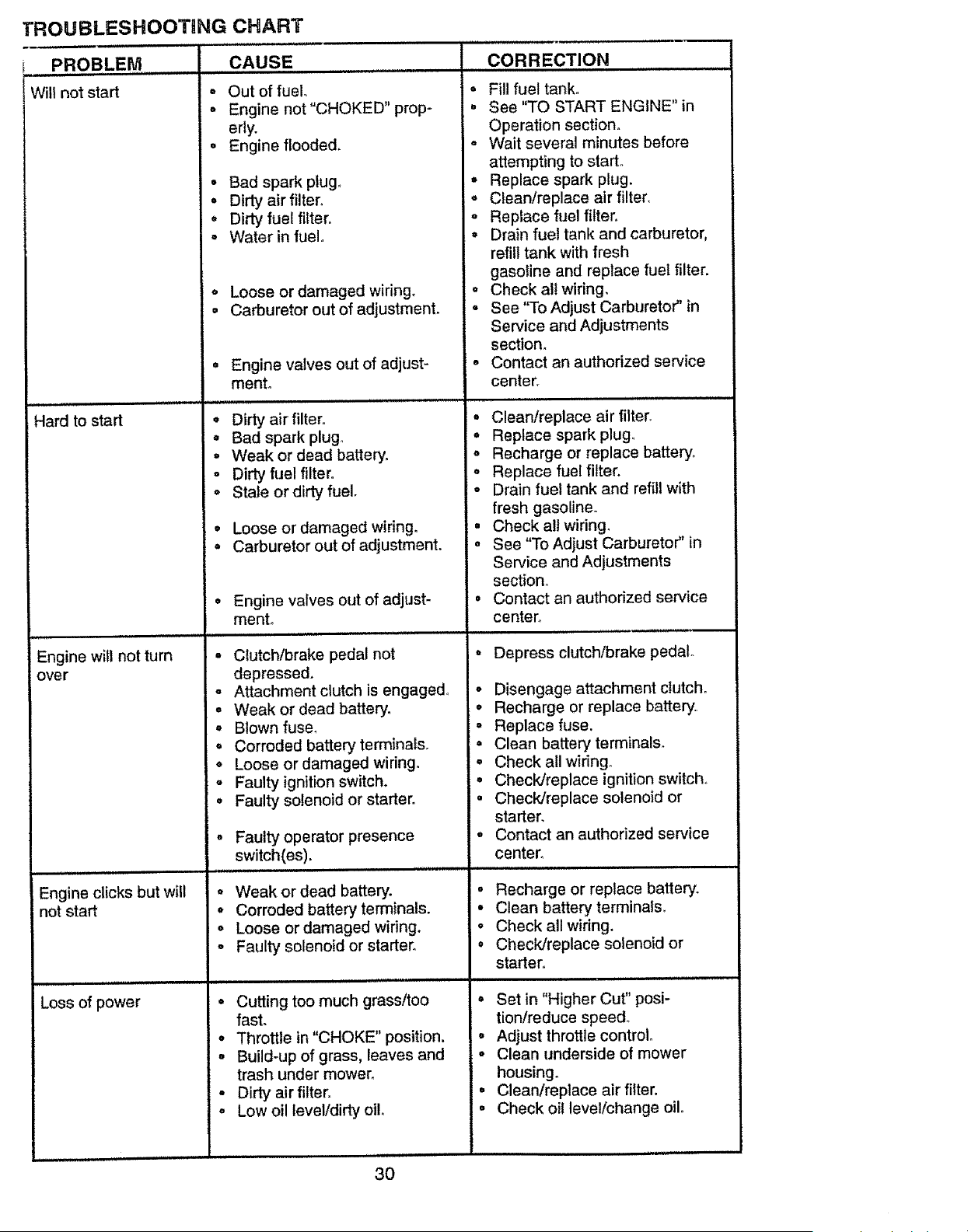
TROUBLESHOOTING CHART
PROBLEM , CAUSE
± .... =l ,,n,,,,,, ,i
Will not start - Out of fuel.
Hard to start
Engine will not turn
over
o Engine not"CHOKED" prop-
edy.
o Engine flooded.
• Bad spark plug,
• Dirty air filter.
, Dirty fuel filter.
° Water in fuel.
o Loose or damaged wiring.
= Carburetor out of adjustment.
• Engine valves out of adjust-
ment.
i ,,a *, i i,in, i ,,,,,i
@
CORRECTION
° Fill fuel tank°
. See "TO START ENGINE" in
Operation section,
o Wait several minutes before
attempting to starL
° Replace spark plug.
• Cleanlreplace air filter,
= Replace fuel filter.
= Drain fuel tank and carburetor,
refill tank with fresh
gasoline and replace fuel filter.
• Check all wiring,
• See "To Adjust Carburetor" in
Service and Adjustments
section_
- Contact an authorized service
center.
Dirty air filter. °
i i,
Clean/replace air filter.
° Bad spark plug_
o Weak or dead battery.
o Dirty fuel filter.
o Stale or dirty fuel.
° Replace spark plugo
° Recharge or replace battery.
° Replace fuel filter,
° Drain fuel tank and refill with
fresh gasoline.
Engine clicks but will
not start
i Ill I, i
Loss of power
Loose or damaged wiring.
Carburetor out of adjustment. =
Engine valves out of adjust-
mento
• Ctutchlbrake pedal not
depressed.
o Attachment clutch is engaged°
° Weak or dead battery.
° Blown fuse.
o Corroded battery terminals.
° Loose or damaged widng.
• Faulty ignition switch.
o Faulty solenoid or starter.
Faulty operator presence
switch(es).
° Weak or dead battery.
° Corroded battery terminals.
° Loose or damaged wiring.
o Faulty solenoid or starter.
• Cutting too much grass/too
fast°
° Throttle in "CHOKE" position.
• Build-up of grass, leaves and
trash under mower.
• Dirty air filter.
° Low oil level/dirty oil.
Check all wiring.
See "To Adjust Carburetor" in
Service and Adjustments
section°
Contact an authorized service
center°
Depress clutchlbrake pedal.
• Disengage attachmentclutcho
• Recharge or replace battery
o Replace fuse.
° Clean battery terminals.
• Check all widng.
• Check!replace ignition switch.
, Check/replace solenoid or
starter.
, Contact an authorized service
center.
° Recharge or replace battery.
• Clean battery terminals.
• Check all wiring.
° Check/replace solenoid or
starter.
° Set in "Higher Cut" posi-
tionfreduce speed°
° Adjust throttle control°
o Clean underside of mower
housing.
• Clean/replace air filter.
° Check oil level/change oilo
30

TROUBLESHOOTING CHART
PROBLEM CAUSE CORRECTION
Loss of power (cont'd) , Faulty spark plug. • Clean and regap or change
spark plugo
o Dirty fuel filter. . Replace fuel filter°
• Stale or dirty fuel. ° Drain fuel tank and refill with
fresh gasoline.
o Water in fuelo o Drain fuel tank and carburetor,
refill tank with fresh gasoline and
replace fuel filter°
o Spark plug wire loose. • Connect and tighten spark plug
wire.
o Dirty engine air screen/fins. ° Clean engine air screen/fins.
° Dirty/clogged muffler° ° Clean/replace muffler_
• Loose or damaged wiring. ° Check all wiring°
o Carburetor out of adjustment° o See "To Adjust Carburetor" in
Service and Adjustments
section_
• Engine valves out of adjust- o Contact an authorized service
mento center.
i ill llllll i,H ,i,Hi,ll,i ,,
Excessive vibration o Worn, bent or loose blade. ° Replace blade. Tighten blade
Engine continues to
run when operator
leaves seat with at
tachment clutch
engaged
ill
Poor cut uneven
Mower blades will not
rotate
Poor grass discharge
° Bent blade mandrel.
- Loose/damaged part(s)_
o Faulty operator-safety pres-
ence control system,
o
o
°
o
Ii
Worn, bent or loose blade.
Mower deck not level°
Buildup of grass, leaves, and
trash under mower..
Bent blade mandrel.
Clogged mower deck vent
holes from buildup of
grass, leaves, and trash
around mandrels.
bolt.
Replace blade mandrel,
Tighten loose part(s)o Replace
damaged parts.
Check wiring, switches and con-
nections. If not
corrected, contact an authorized
service center/
department.
o Replace blade, Tighten blade
bolt.
o Level mower deck_
o Clean underside of mower hous-
ing..
o Replace blade mandrel.
o Clean around mandrels to open
vent holes.
o
o
0
@
o
Q
0
0
o
Obstruction in clutch mecha-
nism,
Worn/damaged mower drive
belt,
Frozen idler pulley..
Frozen blade mandrel.
i i IH,,H H,H
Engine speed too slow.
Travel speed too fast,
Wet grass.
Mower deck not level.
Low/uneven tire air pressure°
Worn, bent or loose blade.
° Remove obstruction.
° Replace mower drive belt.
• Replace idler pulley.
- Replace blade mandrel,
,Hi,,, II,,,,,lll,'
- Place throttle control in "FAST"
position°
° Shift to slower speed.
• Allow grass to dry before mow-
ing,
° Level mower deck.
• Check tires for proper air pres-
sure.
o Replace!sharpen blade. Tighten
blade bolt.
31
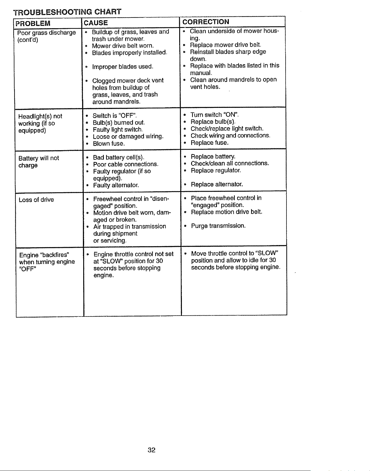
TROUBLESHOOTDNG CHART
PROBLEM CAUSE
Poor grass discharge o Buildup of grass, leaves and
(cont'd) trash under mower.
=,uu ii L ill,
Headlight(s) not
working (if so
equipped)
Battery will not
charge
Loss of drive
Engine "backfires"
when turning engine
"OFF"
= Mower drive belt worn°
• Blades improperlyinstalledo
o Improper blades used.
- Clogged mower deck vent
holes from buildup of
grass, leaves, and trash
around mandrels.
lill ==Lu
• Switch is "OFF".
o Bulb(s) burned out,
• Faulty light switch,
• Loose or damaged wiring.
• Blown fuse.
o
0
0
0
Bad battery cell(s).
Poor cable connections°
Faulty regulator (if so
equipped)°
Faulty alternator.
° Freewheel control in "disen-
gaged" position_
• Motion drive belt worn, dam-
aged or broken.
• Air trapped in transmission
during shipment
or servicing,
i = ,1111
Engine throttle control not set
at "SLOW" position for 30
seconds before stopping
engine°
CORRECTION
o Clean underside of mower hous-
ing.
° Replace mower drive bell
o Reinstall blades sharp edge
down.
= Replace with blades listed in this
manual.
• Clean around mandrels to open
vent holes°
,ul,,i.,
° Turn switch "ON".
° Replace bulb(s)_
o Check/replace light switch.
° Check widng and connections°
o Replace fuse.
• Replace battery.
o Check/clean all connections.
° Replace regulator,
° Replace alternator.
° Place freewheel control in
"engaged" position.
° Replace motion drive belt,
° Purge transmission.
, ii i ,,p,,,,,,i, i=lll
Move throttle control to "SLOW"
position and allow to idle for 30
seconds before stopping engine°
32
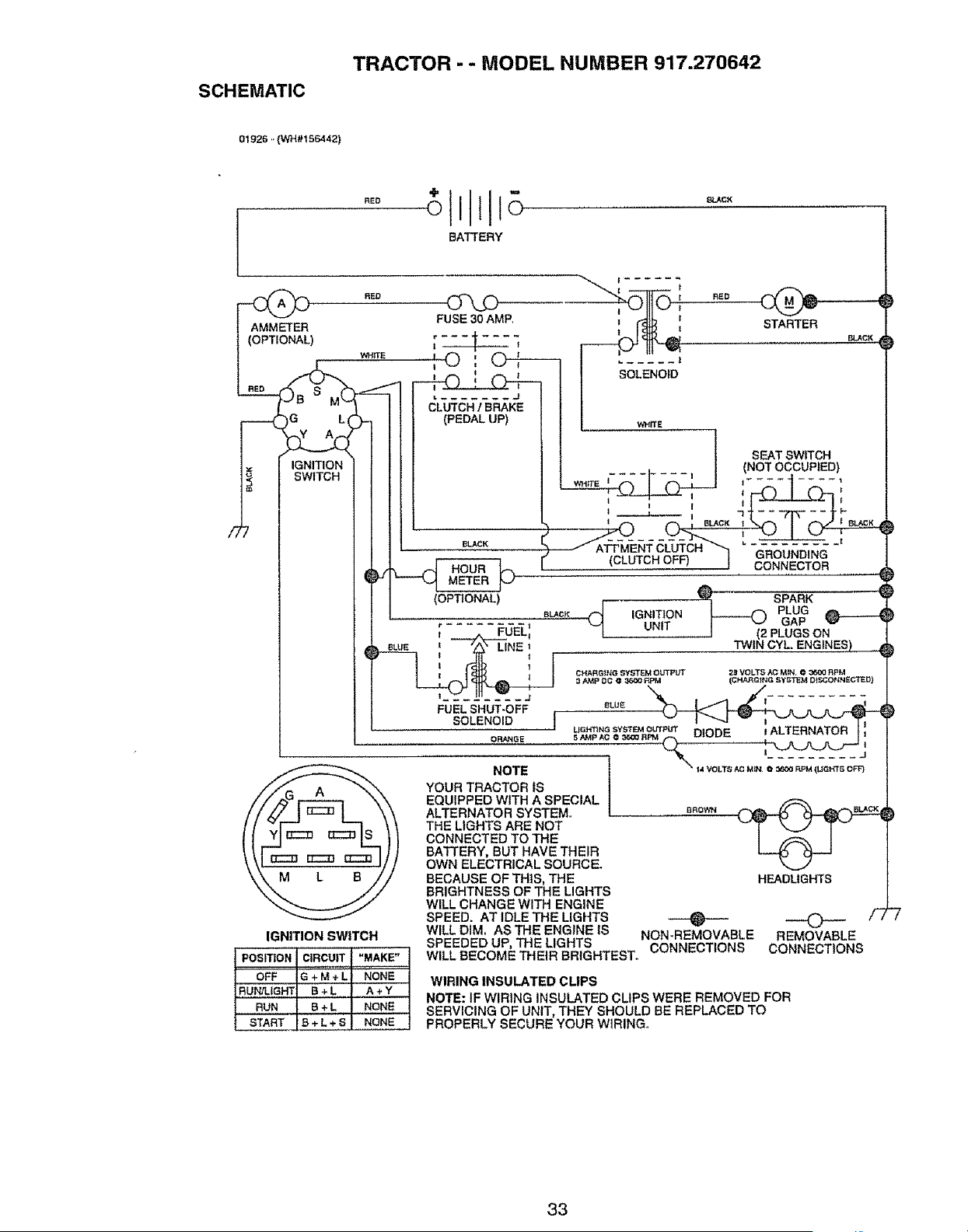
SCHEMATIC
TRACTOR - - MODEL NUMBER 917.270642
01926 ..(WH#t 56442)
"Ill
°Eo olllo
BATTERY
t AM_ER FUSEa0AMP ! _k ', STARTER
WHFfE I _ I
I I"0",. _ I SOLE.O_O
| - '_ CLUTCH / BRAKE
[_ A_}- ] (PEDALUP) _ I-
1 _._ _._.. _ I | SEAT SWITCH
_= l I-LiNII--I-{JN ]I ! (NOTOCCUPtED)
WitITE I........ I I ........
nL_ I I _ i -3 k.
I BLACK ! I BLACK
,
..... CLUTCH OFF) 1 _k"/, 2?,LW"_"_
I II (OPTIONAL) , __
I ! _ BLUE I /A \ LINEr TWIN CYLENGINES)
I II
t i L__ "
1 t.....................0_0E _..,._o_._ Q _'_"'- __',
..... I _-.. _......... J
f/F... A _-.\ YOUR TRACTOR IS I
/,/_L_r--:-:---_ \ _ EQUIPPED WITH A SPECIAL 1
///./ I _ I _\ ALTERNATORSYSTEMo L 8_o_. _
t ( Y_EZ:_ EZ:_S _ THE LIGHTS ARE NOT _ k_j7 T J "
I I ' I _-_ _-= I° II CONNECTED TO THE I /_, I
_ _ _ lZ_ _ BATTERY, BUT HAVE THEIR _ PL.-J
\ \1 _ _ E:_ ,1 OWNELECTRICALSOURCE.
\\ M L B , t BECAUSE OF THIS, THE HEADLIGHTS
"-. ",- / BRIGHTNESS OF THE LIGHTS
"-_"_'_ _ WILL CHANGE WITH ENGINE
SPEED. AT IDLE THE LIGHTS ,0 0 /-)
IGNITION SWITCH
POSITION CIRCUIT "MAKE"
OFF G + M + L NONE
RUN/LIGHT B + L.......A + Y
RUN B + L NONE
WILL DIM, AS THE ENGINE IS NON-REMOVABLE REMOVABLE
SPEEDED UP, THE LIGHTS CONNECTIONS CONNECTIONS
WILL BECOME THEIR BRIGHTEST_
WIRING INSULATED CUPS
NOTE: IF WIRING INSULATED CLIPS WERE REMOVED FOR
SERVICING OF UNIT, THEY SHOULD BE REPLACED TO
PROPERLY SECURE YOUR WIRING.
33
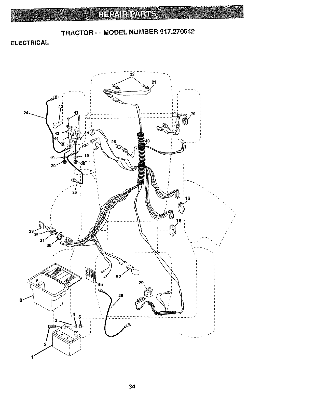
ELECTRICAL
TRACTOR - - MODEL NUMBER 917.270642
J
/
I 1
29
34

ELECTRICAL
TRACTOR - - MODEL NUMBER 917.270642
KEY PART
NO. NO.
1 144925
2 74760412
3 STD551025
4 STD551125
6 STD541025
8 156417
16 153664
19 STD551125
20 73350400
21 147430
22 4t52J
24 4799J
25 146147
26 108824X
28 4207J
29 121305X
30 140301
31 12421tX
32 141226
33 109310X
40 156442
41 71110408
42 131563
43 145673
44 73640400
45 121433X
52 141940
70 140422
DESCRIPTION
Battery 12 VOLT 25 AMP
Bolt Hex Hd 1/4_20uncx 3/4
Washer9/32 x 5/8 x 16Ga
WasherLockHvy Helical1/4
Nut FinHex 1/4-20 Unc
Case Battery
Switch,InterlockPush-In
WasherLock 1/4
NutJam Hex 1/4-20 Uric
HarnessAsm LightW/4152j
Bulb Light#1156
Cable Battery 6 Ga 11=red
Cable Battery 6 Ga w/16 wire red
Fuse 30AMP Auto Green
Cable Ground 6 Ga 12" black
Switch PJungerNc Gray
Switch lgn 4 Pos
Nut ignition
CoverSw Key BIk 1 25 TextSLT
Key IgnMoldedCraftsman
Harnesslgn Man CI Am Hm 97
Bolt BIk.,FinHex 1/4-20 Unc x 1/2
CoverTerminalRed
Soienoid
NutKepsBlk Hex 1/4..20Unc
Ammeter Rectangular6 Amp
ProtectionWire Loop
HarnessEngine B&S 14 OHV
NOTE: All component dimensions given In U,S, inches
1 _nch = 25_4 mm
35
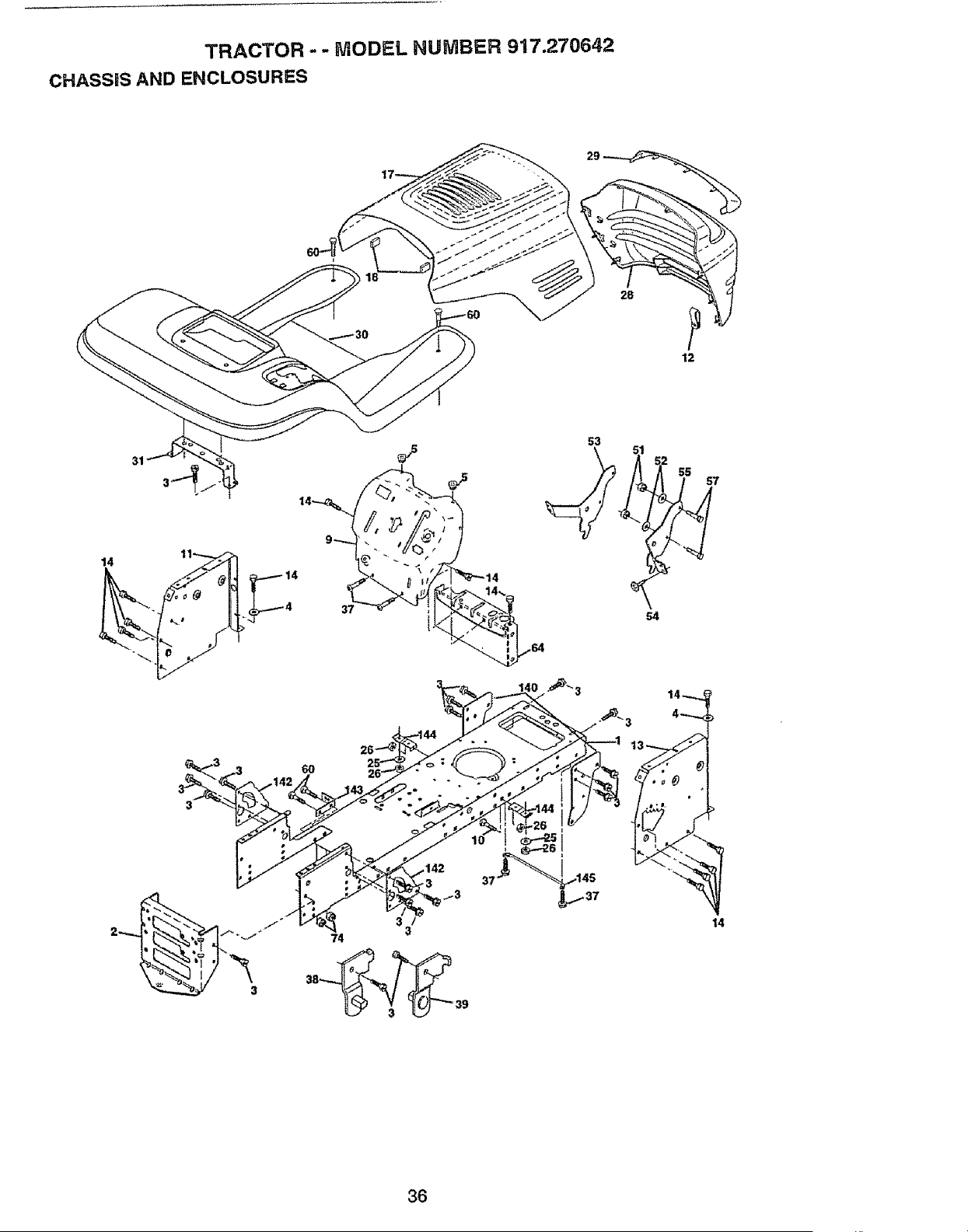
TRACTOR - - MODEL NUMBER 917.270642
CHASSIS AND ENCLOSURES
28
12
@
57
37
54
60
3
37
14
36
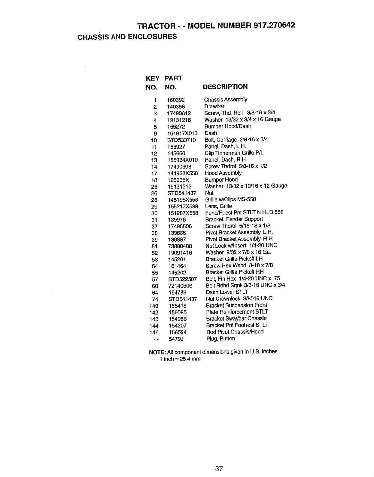
TRACTOR - - MODEL NUMBER 917.270642
CHASSIS AND ENCLOSURES
KEY PART
NO. NO, DESCRIPTION
1 160392
2 140356
3 17490612
4 19131216
5 155272
9 t61917X013
10 STD533710
11 155927
12 145660
13 155934)(010
14 17490608
17 144983X558
t 8 126938X
25 19131312
26 STD541437
28 145198X558
29 155217X599
30 151287X558
31 139976
37 17490508
38 139886
39 139887
51 73800400
52 19091416
53 145201
54 161464
55 145202
57 STD522507
60 72140606
64 154798
74 STD541437
140 158418
142 156095
143 154966
144 154207
145 156524
- 5479J
Chassis Assembly
Drawbar
Screw, Thd. Roll 3/8-16 x 3/4
Washer 13/32 x 3/4 x 16 Gauge
Bumper Hood/Dash
Dash
Bott, Carriage 3/8-16 x 3/4
Panel, Dash, L H,
Clip "rinnerrnan Grille P/L
Panel, Dash, R.H
ScrewThdrol 3/8-16 x 1/2
Hood Assembly
Bumper Hood
Washer t3/32 x 13/16 x 12 Gauge
Nut
Gdlle wlClips MS-558
Lens, Gdlle
Fend/Ftrest Pnt STLT N HLD 558
Bracket, Fender Support
ScrewThdrol 5/16-18 x 1/2
Pivot Bracket Assembly, LHo
Pivot Bracket Assembly, Roll
Nut Lock w/Insert 1/4-20 UNC
Washer 9/32 x 7/8 x 16 Ga.
Bracket Grille Pickoff LH
Screw Hex Wshd 8-t8 x 7/8
Bracket Grille Pickoff RH
Bolt, Fin Hex 1/4-20 UNC x .75
Bolt Rdhd Sqnk 3/8-16 UNC x 3/4
Dash Lower STLT
Nut Crowniock 3/8016 UNC
Bracket Suspension Front
Plate Reinforcement STLT
Bracket Swaybar Chassis
Bracket Pnt Footrest STLT
Rod Pivot Chassis/Hood
Plug, Button
NOTE: All component dimensions given in U..S. inches
I inch = 25A mm
37
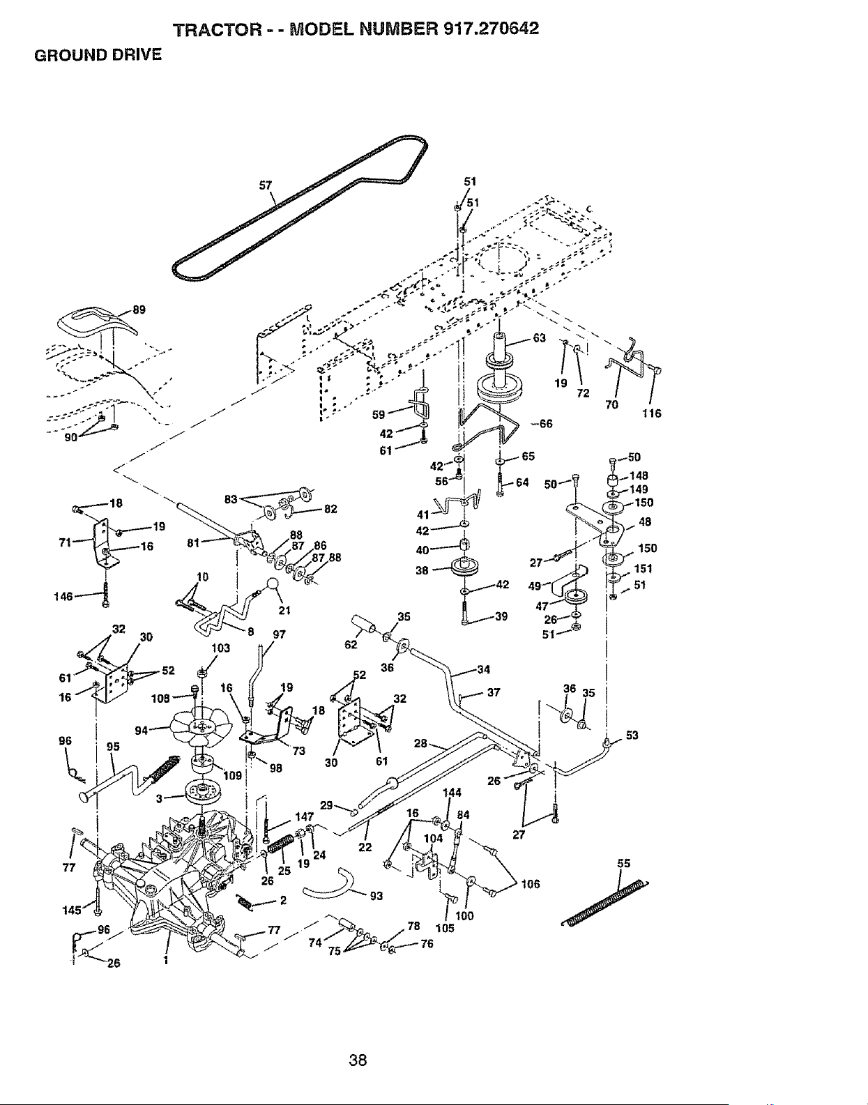
TRACTOR -- MODEL NUMBER 917.27064.2
GROUND DRIVE
57
77
14
I 26 1
53
38
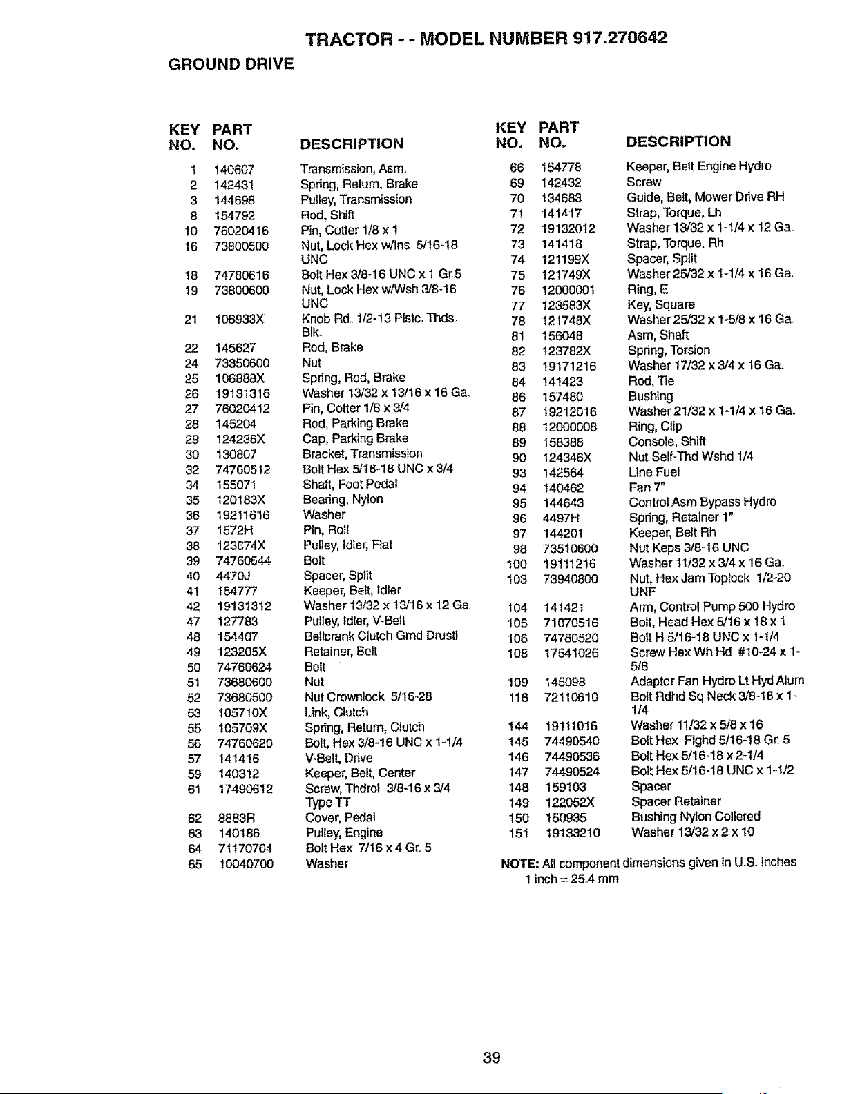
TRACTOR - - MODEL NUMBER 917.270642
GROUND DRIVE
KEY PART
NO. NO,
1 140607
2 142431
3 144698
8 154792
t0 76020416
16 73800500
18 74780616
19 73800600
21 106933X
22 145627
24 73350600
25 106_88X
26 19131316
27 76020412
28 145204
29 124236X
30 130807
32 74760512
34 155071
35 120183X
36 19211616
37 1572H
38 123874X
39 74760644
40 4470J
4I t 54777
42 19131312
47 127783
48 154407
49 123205X
50 74760624
51 73880600
52 73680500
53 I057t0X
55 105709X
56 74760620
57 141416
59 140312
61 17490612
62 6863R
63 140186
54 71170764
65 10040700
KEY PART
DESCRIPTION NO. NO.
Transmission, Asm. 66 154778
Spring, Return, Brake 69 142432
Pulley, Transmission 70 134683
Rod, Shift 71 141417
Pin, Cotter 1t8 x I 72 19132012
Nut, Lock Hex w/Ins 5/16-18 73 141418
UNC 74 121199X
Bolt Hex 3/8-16 UNC x 1 Gr.5 75 121749X
Nut, Lock Hex w/Wsh 3/8-16 76 12000001
UNC 77 123583X
Knob Rd.. 112-13 Plstc.. Thds 78 121748X
Blk_ 81 156048
Rod, Brake 82 123782X
Nut 83 19171216
Spring, Rod, Brake 84 141423
Washer 13/32 x 13/16 x 16 Ga. 86 157480
Pin, Cotter 1/8 x 3/4 87 19212016
Rod, Parking Brake 88 12000008
Cap, Parking Brake 89 158388
Bracket, Transmission 90 124346X
Bolt Hex 5/16-18 UNC x 3/4 93 142564
Shaft, Foot Pedal 94 140462
Bearing, Nylon 95 144643
Washer 96 4497H
Pin, Rotf 97 144201
Pulley, idler, Flat 98 73510600
Bolt 100 19111216
Spacer, Split ! 03 73940800
Keeper, Belt, idler
Washer 13/32 x 13/16 x 12 Ga 104 141421
Pulley, idler, V-Belt 105 71070516
Bellcrank Clutch Gmd Drustl 106 74780520
Retainer, Bell 108 17541026
Bolt
Nut 109 145098
NutCrownlock 5/16-28 116 72110610
Unk, Clutch
Spring, Return, Clutch 144
Bolt, Hex 3/8-t6 UNC x 1-1/4 t45
V-Be_t, Drive 146
Keeper, Belt, Center 147
Screw, Tl_rol 3/8-16 x 3/4 148
Type -rT 149
Cover, Pedal 150
Pulley, Engine 151
Bolt Hex 7/16 x4 Gr. 5
Washer
DESCRIPTION
Keeper, Belt Engine Hydro
Screw
Guide, Be{t, Mower Drive RH
Strap, Torque, Lh
Washer 13/32 x 1-1/4 x 12 Ga.
Strap, Torque, Rh
Spacer, Split
Washer 25/32 x I-1/4 x 16 Ga,
Ring, E
Key, Square
Washer 25/32 x 1-5/8 x 16 Ga.
Asm, Shaft
Spring, Torsion
Washer 17/32 x3/4x 16 Ga..
Rod, Tie
Bushing
Washer 21132 x 1-114x 16 Gao
Ring, Clip
Console, Shift
Nut Self-Thd Wshd 1/4
Une Fuel
Fan 7"
Control Asm Bypass Hydro
Spring, Retainer 1"
Keeper, Belt Rh
Nut Keps 3/8-16 UNC
Washer 11/32 x3/4 x 16 Ga.
Nut, Hex JamToplock 1/2-20
UNF
Arm, Control Pump 500 Hydro
Bolt, Head Hex 5/16 x t8 x 1
Bolt H 5/16-!8 UNC x 1-1/4
Screw Hex Wh Hd #10-24 x I-
5/8
Adaptor Fan Hydro Lt Hyd Alum
Bolt Rdhd Sq Neck 3/8-16 x 1-
1/4
191110t6 Washer 11/32 x 5/8 x 16
74490540 Bolt Hex Flghd 5/t6-18 Gr. 5
74490536 Bolt Hex 5/16-18 x 2-1/4
74490524 Bolt Hex 5/16-18 U NC x 1-1/2
159103 Spacer
122052X Spacer Retainer
150935 Bushing Nylon Collered
19133210 Washer 13/32 x 2 x 10
NOTE: All componentdimensionsgiven inU°S. inches
1inch = 25,4 mm
39
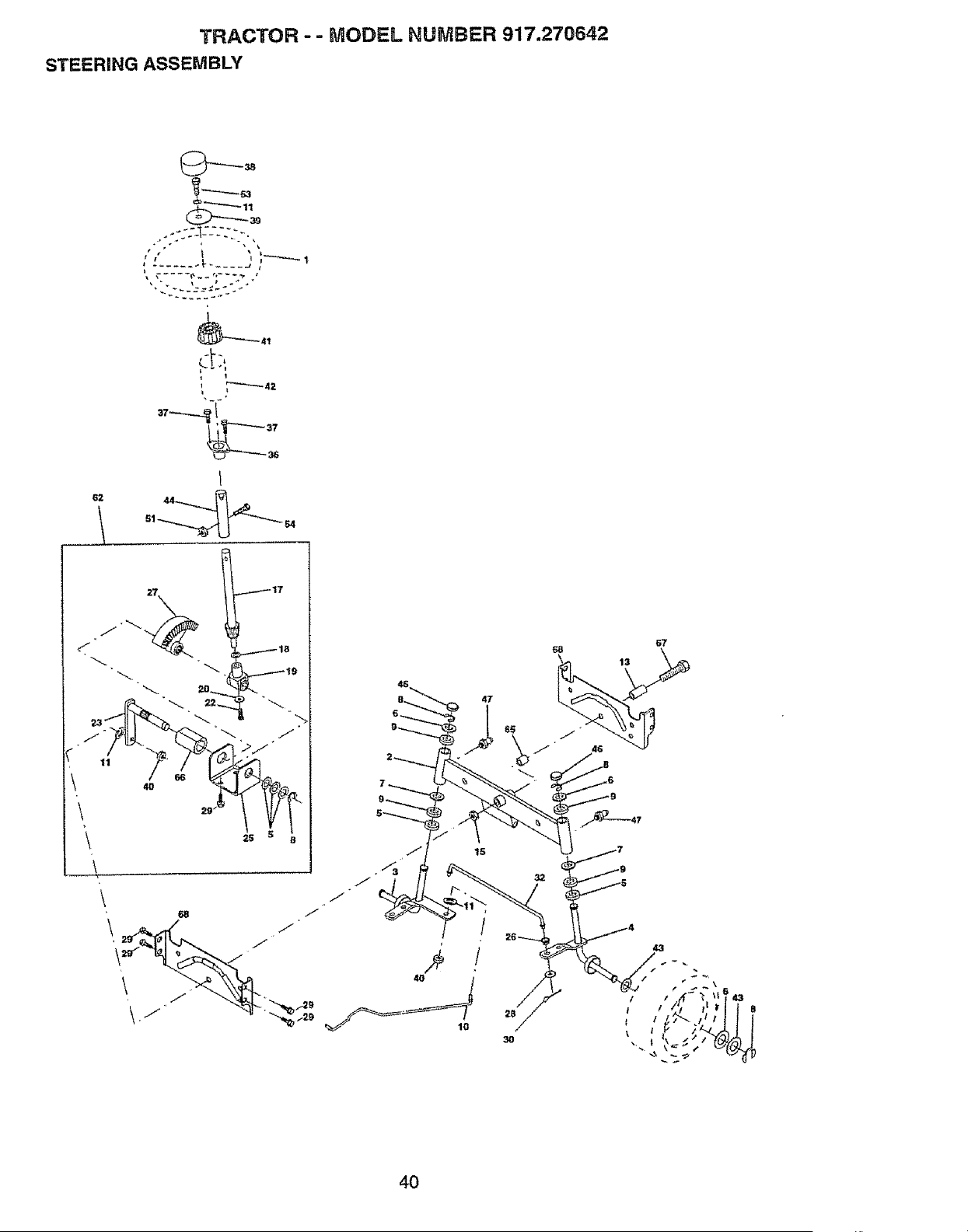
TRACTOR - - MODEL NUMBER 917.270642
STEERING ASSEMBLY
_-°,
!
62 44
30
43
t I
4O
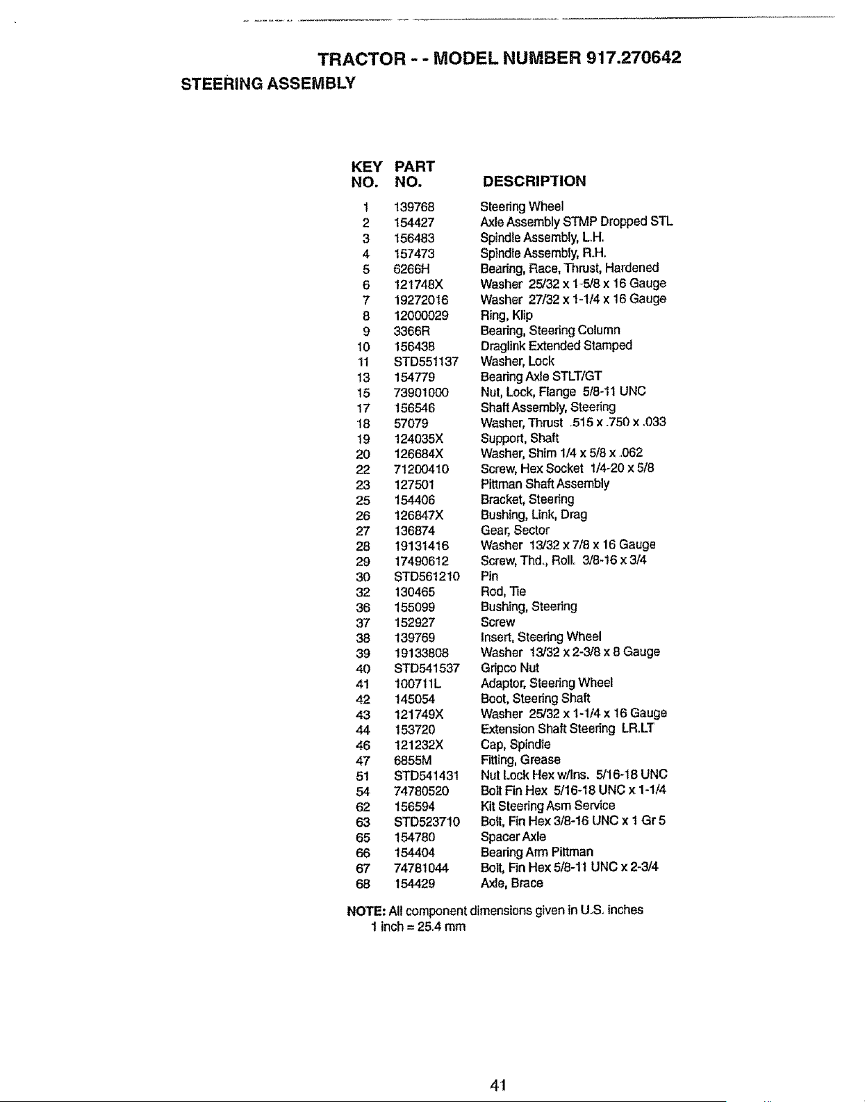
TRACTOR - - MODEL NUMBER 917.270642
STEERING ASSEMBLY
KEY PART
NO. NO. DESCRIPTION
1 139768
2 154427
3 156483
4 157473
5 6266H
6 121748X
7 192720 t 6
8 12000029
9 3366R
10 156438
11 STD55t137
13 154779
15 73901000
17 156546
18 57079
19 124035X
20 126684X
22 71200410
23 127501
25 154406
26 126847X
27 136874
28 19131416
29 17490612
30 STD5612t0
32 130465
36 155099
37 152927
38 139769
39 19133808
40 STD541537
41 100711L
42 145054
43 121749X
44 153720
46 121232X
47 6855M
51 STD541431
54 74780520
62 156594
63 STD523710
65 15478O
66 154404
67 74781044
68 154429
SteeringWheel
Axle Assembly STMP DroppedSTL
SpindleAssembly,L.H..
SpindleAssembly, R.H,
Bearing, Race, Thrust, Hardened
Washer 25/32 x 1_5/8x 16 Gauge
Washer 27/32 x 1-1/4 x 16 Gauge
Ring,Klip
Bearing, Steering Column
DraglinkExtendedStamped
Washer,Lock
BearfngAxleSTLT/GT
Nut, Lock, Flange 5/8-11 UNC
ShaftAssembly, Steering
Washer,Thrust .515 x .750 x .033
Support, Shaft
Washer, Shim 1/4x 5/8 x ..062
Screw, Hex Socket t/4_20 x 5t8
PittmanShaft Assembly
Bracket,Steering
Bushing, Link, Drag
Gear, Sector
Washer 13/32 x 7/8 x 16 Gauge
Screw,Thd., Roll.. 3t8-16 x 3/4
Pin
Rod,Tie
Bushing,Steering
Screw
Insert,Steering Wheel
Washer 13/'32x 2-3/8 x 8 Gauge
Gripco Nut
Adaptor,SteeringWheel
Boot, Steering Shaft
Washer 25/32 x 1-1/4 x I6 Gauge
Extension Shaft Steering LR.LT
Cap, Spindle
Fitting,Grease
Nut Lock Hex w/Ins. 5/16-18 UNC
Bolt Fin Hex 5/16-18 UNC x 1-1/4
Kit SteeringAsm Service
Bolt,Fin Hex 3/8-16 UNC x I Gr 5
SpacerAxle
BearingArmPittman
Bolt, FinHe× 5/8-11 UNC x 2-3/4
Axle, Brace
NOTE: All component dimensions given tn U.S. inches
1 inch= 25.4 mm
41
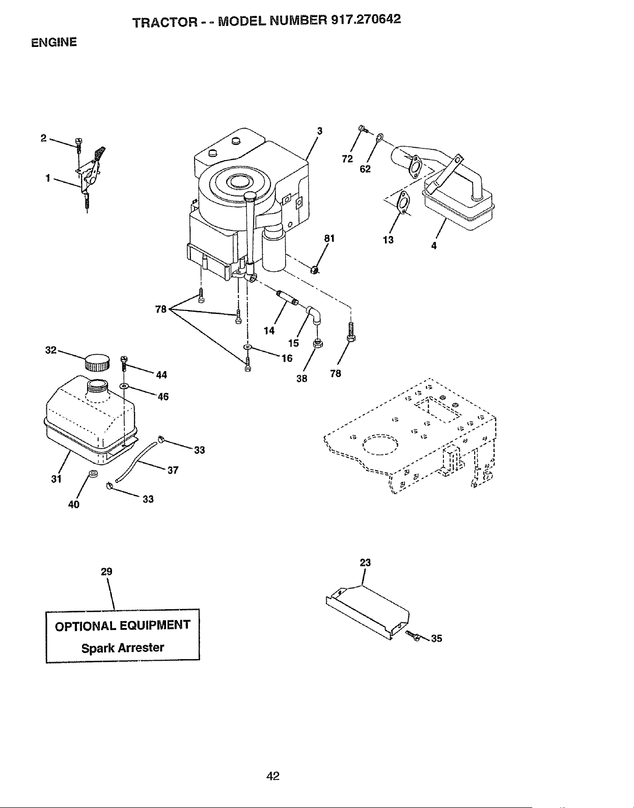
ENGINE
TRACTOR -- MODEL NUMBER 917.270642
81
38 78
33
37
7
4
"===_ .... .-" t'r,;_.- t_ '
29
,,, ,,
OPTIONAL EQUIPMENT
Spark Arrester
23
35
42
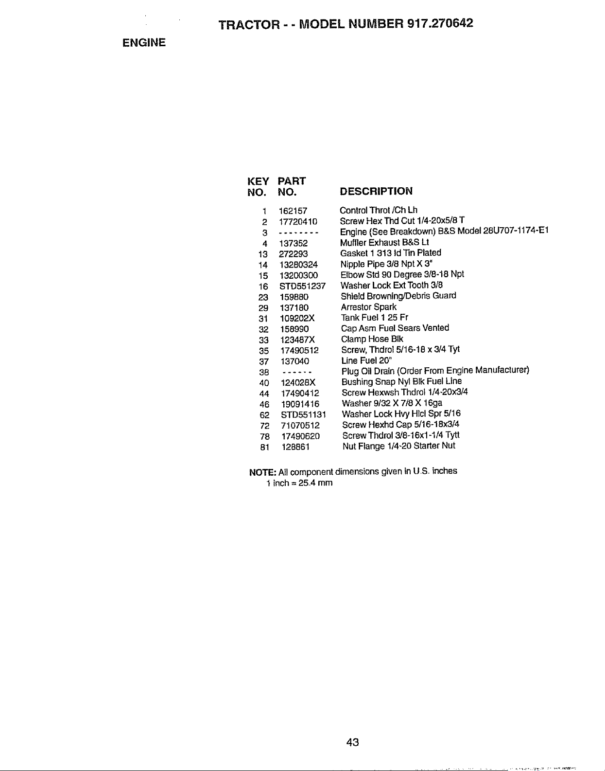
ENGINE
TRACTOR - - MODEL NUMBER 917.270642
KEY PART
NO. NO. DESCRIPTION
t 162157
2 17720410
4 137352
13 272293
14 13280324
15 13200300
16 STD551237
23 159980
29 137180
31 109202X
32 158990
33 123487X
35 17490512
37 t37040
38 ......
40 124028X
44 17490412
46 19091416
62 STD551131
72 71070512
78 17490620
81 128861
ControlThrot/Ch Lh
ScrewHex Thd Cut 1/4-20x5/8T
Engine(See Breakdown) B&S Model 28UT07-1174-E1
MufflerExhaustB&S Lt
Gaskett 313 Id TinPlated
Nipple Pipe 3/8 Npt X 3"
ElbowStd 90 Degree3/6-18 Npt
WasherLockExt Tooth3/8
ShietdBrowning!DebrisGuard
Arrestor Spark
TankFuel 1 25 Fr
Cap Asm FuelSearsVented
ClampHose BIk
Screw,Thdrot 5116+18x 3/4 Tyt
Line Fuel 20"
Plug Oil Drain (Order From Engine Manufacturer)
Bushing Snap Nyt Blk Fuel Line
Screw Hexwsh Thdrof 1/4-20x3/4
Washer 9/32 X 7/8 X 16ga
Washer Lock Hvy Hlcl Spr 5/16
Screw Hexhd Cap 5/16-18x314
Screw Thdrol 3/8+16x1-1/4Tytt
Nut Flange 114-20Starter Nut
NOTE: All component dimensions given in U S+ inches
t inch = 25+4 mm
43
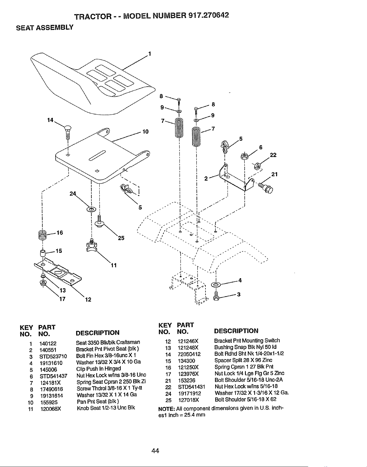
TRACTOR -- MODEL NUMBER 917.270642
SEAT ASSEMBLY
17 12
5
25
KEY
NO,
1
2
3
4
5
6
7
8
9
10
11
PART
NO,
140122
140551
STD5237t0
19131610
145O06
STD541437
124181X
17490616
19131614
155925
120068X
DESCRIPTION
Seat 3350 BIk/blkCraftsman
BracketPnt PivotSeat (btk)
Bolt Fin Hex 3/8-16uncX 1
Washer13/32X 3/4 X t0 Ga
Cl_pPush In Hinged
Nut HexLock w/Ins3/8-16Uric
SpringSeatCprsn 2 250 BtkZt
ScrewThdrol3/8-16 X 1 Ty-tt
Washert3/32 X t X 14 Ga
PanPntSeat(bik)
KnobSeat 1/2-13UncB{k
KEY PART
NO. NO. DESCRIPTION
12 121246X
13 121248X
14 72050412
15 134300
16 121250X
17 123976X
21 153236
22 STD541431
24 19171912
25 127018X
BracketPnt Mounting Switch
Bushing Snap BIk Ny150 Id
Bolt Rdhd Sht Nk 1/4-20xf-1/2
Spacer Split 28 X 96 Zinc
Spring Cprsn 127 BIk Pnt
Nut Lock1/4 Lge Rg Gr 5 Zinc
Bolt Shoulder5/16-18 Unc-2A
Nut Hex Lockw/Ins5/16-18
Washer 17132X 1-3/16X 12 Gao
Bolt Shoulder5/16-t8 X 62
NOTE: All component dimensions given in U,S inch-
esl inch= 25A mm
44
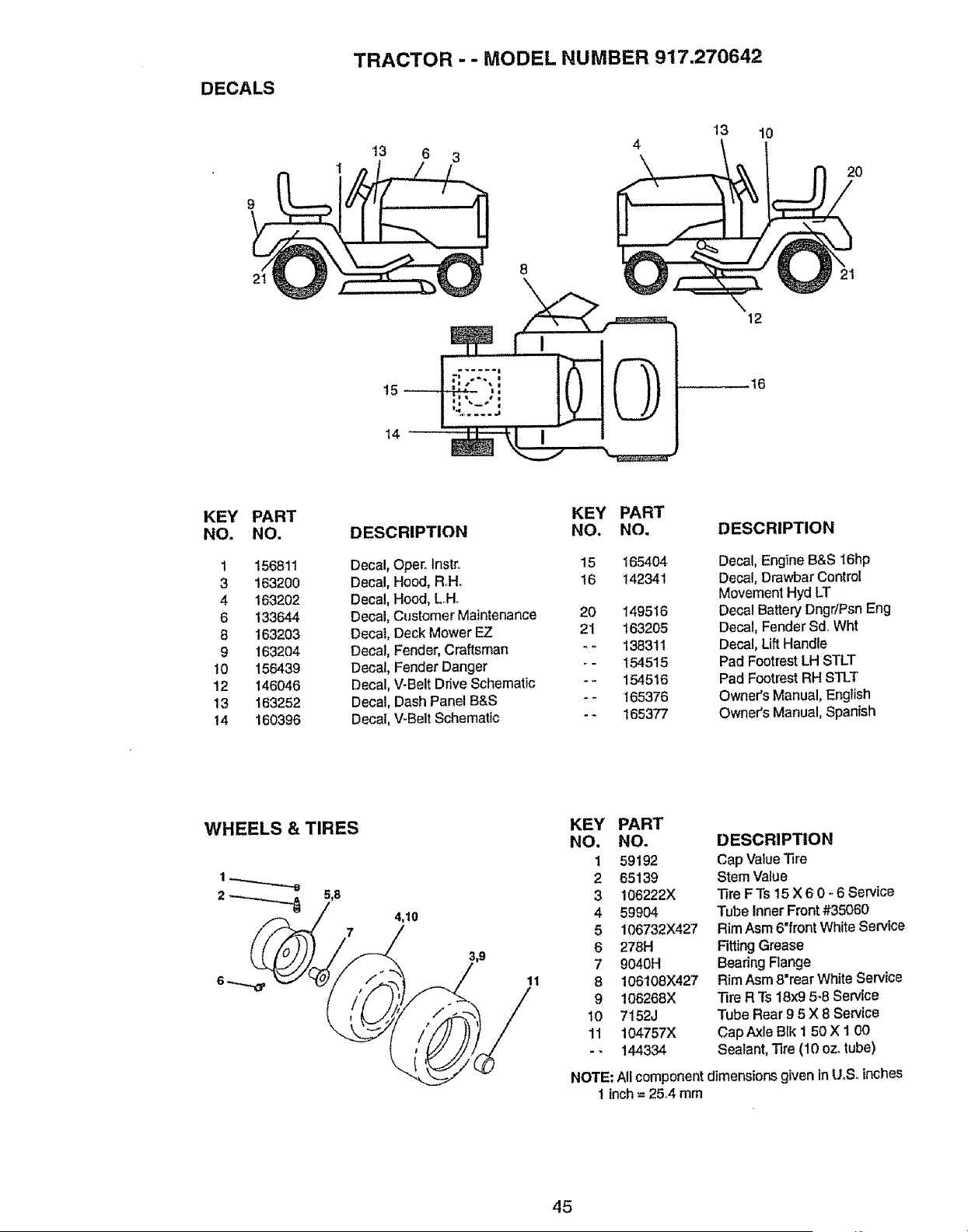
DECALS
TRACTOR -- MODEL NUMBER 917.270642
13 6 3
13
10
2O
8
14 _
12
t6
KEY
NO,
PART
NO.
1 156811
3 163200
4 163202
6 133644
8 163203
9 1632o4
10 156439
12 146046
13 163252
t 4 160396
DESCRIPTION
KEY PART
NO. NO.
Decal, Oper_Instr. 15 165404
Decal, Hood, RHo 16 142341
Decal, Hood, LH
Decal, Customer Maintenance 20 149518
Decal, Deck Mower EZ 21 163205
Decal, Fender,Craftsman - - 138311
Decal, Fender Danger - - 154515
Decal, V-BeltDrive Schematic - - 154516
Decal, Dash Panel B&S - ° 165376
Decal, V-BeltSchematic - - 165377
DESCRIPTION
Decal, Engine B&S 16hp
Decal, Drawbar Control
Movement Hyd LT
Decal Battery Dngr/Psn Eng
Decal, Fender Sd. Wht
Decal, Lift Handle
Pad FootrestLH STLT
Pad Footrest RH STLT
Owner's Manual, English
Owner's Manual, Spanish
WHEELS & TIRES
4,10
11
KEY PART
NO. NO.
1 59192
2 65139
3 106222X
4 59904
5 106732X427
6 278H
7 9040H
8 106108X427
9 t06268X
10 7152J
11 !04757X
- - 144334
DESCRIPTION
Cap ValueTire
Stem Value
Tire FTs 15 X 6 0 - 6 Service
Tube Inner Front #35060
RimAsm 6"front White Service
Fitting Grease
Beadng Flange
RimAsm 8"rear White Service
Tire R "is18x9 5-8 Service
Tube Rear 9 5 X 8 Service
Cap Axle Blk 1 50 X 1 00
Sealant, Tire (10 oz.tube)
NOTE:Allcomponentdimensions given in U.Soinches
1 inch= 25_4mm
45
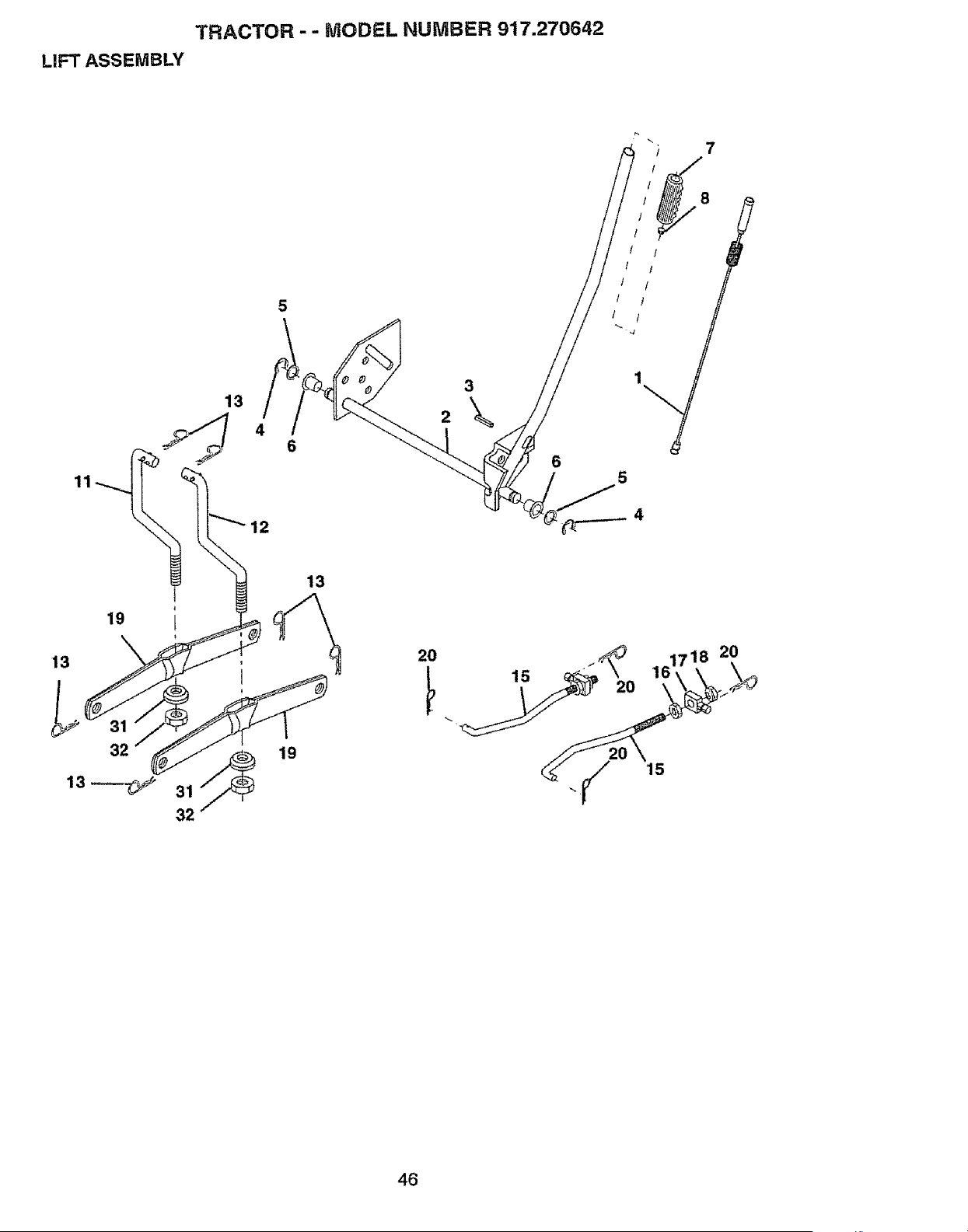
TRACTOR-- MODEL NUMBER 917.270642
LIFT ASSEMBLY
7
11
13
12
6
8
/ /
l /
t l
t /
5
19
13
32
13
19
20
161718 20
15
46

TRACTOR - - MODEL NUMBER 917.270642
LIFT ASSEMBLY
KEY PART
NO. NO. DESCRIPTION
1 159460 Washer Asm Inner Spring W/Plunger
2 159471 ShaftAsm. Uft
3 105767X Pin Groove
4 12000002 E Ring #5133-62
5 19211621 Washer 21!32 x 1 x21 Ga.
6 120183X Beadng Nylong
7 125631X Grip Hand{e Ftuted
8 122365X Button Plunger Read
11 139865 Link Asm Lift LH.
12 139866 LtnkAsm Lift RH
13 4939M Retainer Spring
15 127218 Link Front
16 73350800 Nut JamHex 1/2-13 Unc
17 130171 Trunnion BIkZinc
18 73680800 Nut Crownlock 1/2-'t3 Unc
19 139868 Arm Suspension Mower
20 163552 Retainer Spring
31 140302 Bearing, Pvt Lift° SphericaI
32 73540600 Nut Crown!ock 3/8-24
NOTE: All component dimensions given in USo inches
1 inch = 25.4 mm
47
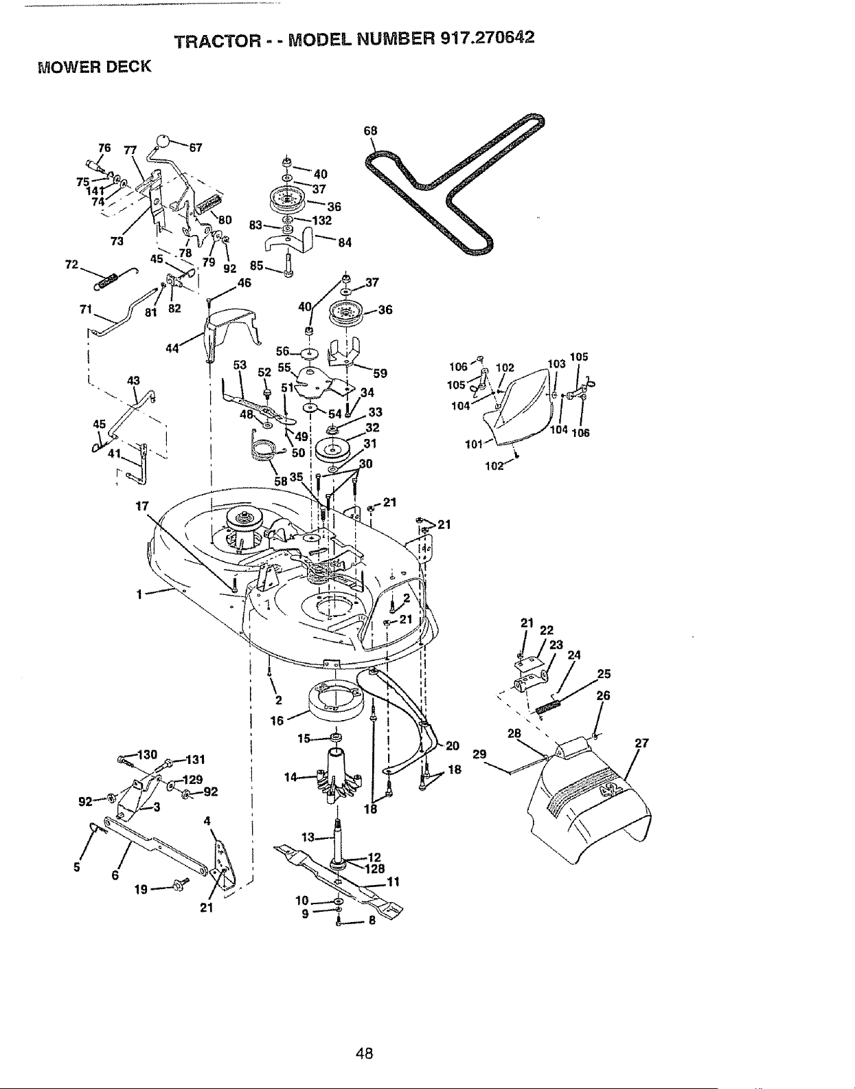
TRACTOR = - MODEL NUMBER 917.270642
MOWER DECK
17
\
>21
105
t03
_106
21
29
,18
22
24
25
27
48
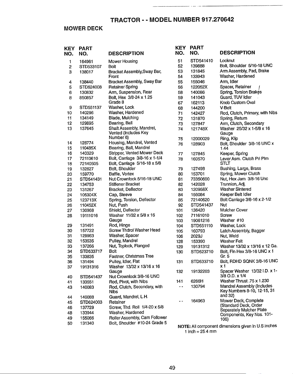
TRACTOR - - MODEL NUMBER 917.270642
MOWER DECK
KEY PART KEY PART
NO. NO. DESCRIPTION NO. NO.
1 164961 Mower Housing 51 STD541410
2 STD533107 Bolt 52 139888
3 138017 Bracket Assembly, Sway Bar, 53 131845
Front 54 133943
4 138440 Bracket Assembly, Sway Bar 55 155046
5 STD624008 Retainer Spring 56 122052X
6 130832 Arm, Suspension, Rear 58 140086
8 850857 Bolt, Hex 3/8-24 x 1.25 59 141043
Grade 8 67 162113
9 STD551137 Washer, Lock 68 144200
10 140296 Washer, Hardened 7t 142427
1t 134149 Blade, Mulching 72 131870
12 129895 Bearing, Ba!l 73 127847
13 137645 Shaft Assembly, Mandrel, 74 121748X
Vented (includes Key
Number 6) 75 t 2000029
14 128774 Housing, Mandrel, Vented 76 128903
15 110485X Bearing, Ball, Mandrel
16 140329 Stripper' Vented Mower Deck 77 t27845
17 72110810 Boit, Carriage 3/8-16 x t-1/4 78 160570
18 72140505 Bolt, Canfage 5/16-18 x 5/8
19 132827 Bolt, Shoulder 79 t 27498
20 159770 Baffle, Vortex 80 153701
21 STD541431 Nut Crownlock 51t6_18 LJNC 81 73350600
22 134753 Stiffener Bracket 82 142028
23 131267 Bracket, Deflector 83 120958X
24 105304X Cap, Sleeve 84 156084
25 123713X Spring, Torsion, Deflector 85 72140620
26 110452X Nut, Push 92 STD541437
27 130968 ShieId, Deflector 101 136420
28 19111016 Washer 1t/32 x 5/8 x 16 102 71161010
Gauge 103 1906t216
29 131491 Rod, Hinge I04 STD551110
30 157722 Screw Thdrol Washer Head I05 160793
31 129963 Washer, Spacer 106 2029J
32 153535 Putley, Mandrel !28 153390
33 137266 Nut, Teplock, Flanged 129 19131312
34 STD533717 Bolt 130 STD523710
35 133835 Fastner, Christmas Tree
36 131494 Pulley, Idler, Fiat 131 STD533710
37 19131316 Washer 13/32 x 13/16 x 16
Gauge 132 19132203
40 STD541437 Nut Crownlock 3/8-16 UNC
41 133551 Rod, Pivot, with Nibs 141 6266H
43 140083 ROd, Clutch, Secondary, with _- 130794
Nibs
44 140088 Guard, Mandrel, L.H.
45 STD624003 Retainer - - '164963
46 137729 Screw, Thd, Roll 1/4_20 x 5/8
48 133944 Washer, Hardened
49 155066 RollerAssembly, Cam Follower
50 131340 Bolt, Shoulder #10-24 Grade 5
NOTE: AJIcomponent
I inch = 25.4 mm
DESCRIPTION
Locknut
Bolt, Shoulder 5/16-18 UNC
Arm Assembly, Pad, Brake
Washer, Hardened
Arm, Idler
Spacer, Retainer [
Spring, Torsion Brakes
Guard, TUV Idler .
Knob Custom Oval
V-Belt
Rod, Crutch, Primary, with Nibs
Spring, Retum
Arm, Clutch, Secondary
Washer 25/32 x 1-5/8 x 16
Gauge
Ring, Kfip
Bolt, Shoulder 3/8-16 UNC x
1.44
Keeper, Spring
LeverAsmo Clutch Pri PIm
STLT
Bushing, Large, Brass
Sp.dng, Mower Ctutch
Nut, HexJam 3/8-16 Uric
Tru nnion, Adj.
Washer Sintered
Keeper Belt ldter
Bolt Carriage 318_16x 2_1/2
Nut
Mulcher Cover
Screw
Washer #10
Washer, Lock
Latch Assembly, Bagger
Nut, Weld
Washer Felt
Washer 13/32 x 13/16 x 12 Gao
Boff, Fin Hex3/8-16 UNC x 1
Gr. 5
Bolt, RDHD SQNK 3/8-16 UNC
xl
SpacerWasher 13/32 LD. x 1-
3/80.D. x 1/4
Washer Thrust .75 x 1°230
Mandrel Assembly (Includes
Key Numbers 8_10, 12_15, 31
and 32)
Mower Deck, Complete
(Standard Deck, Order
Separately Mulcher Plate
Components, Key Nos. 101-
106)
dimensions given in U.Sinches
49
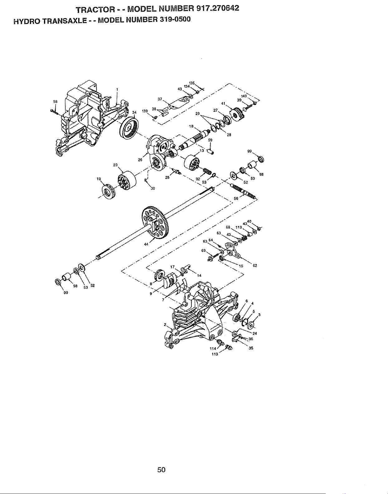
TRACTOR - - MODEL HUMBER 917.270642
HYDRO TRANSAXLE - - MODEL NUMBER 319-0500
99
23
19
5O
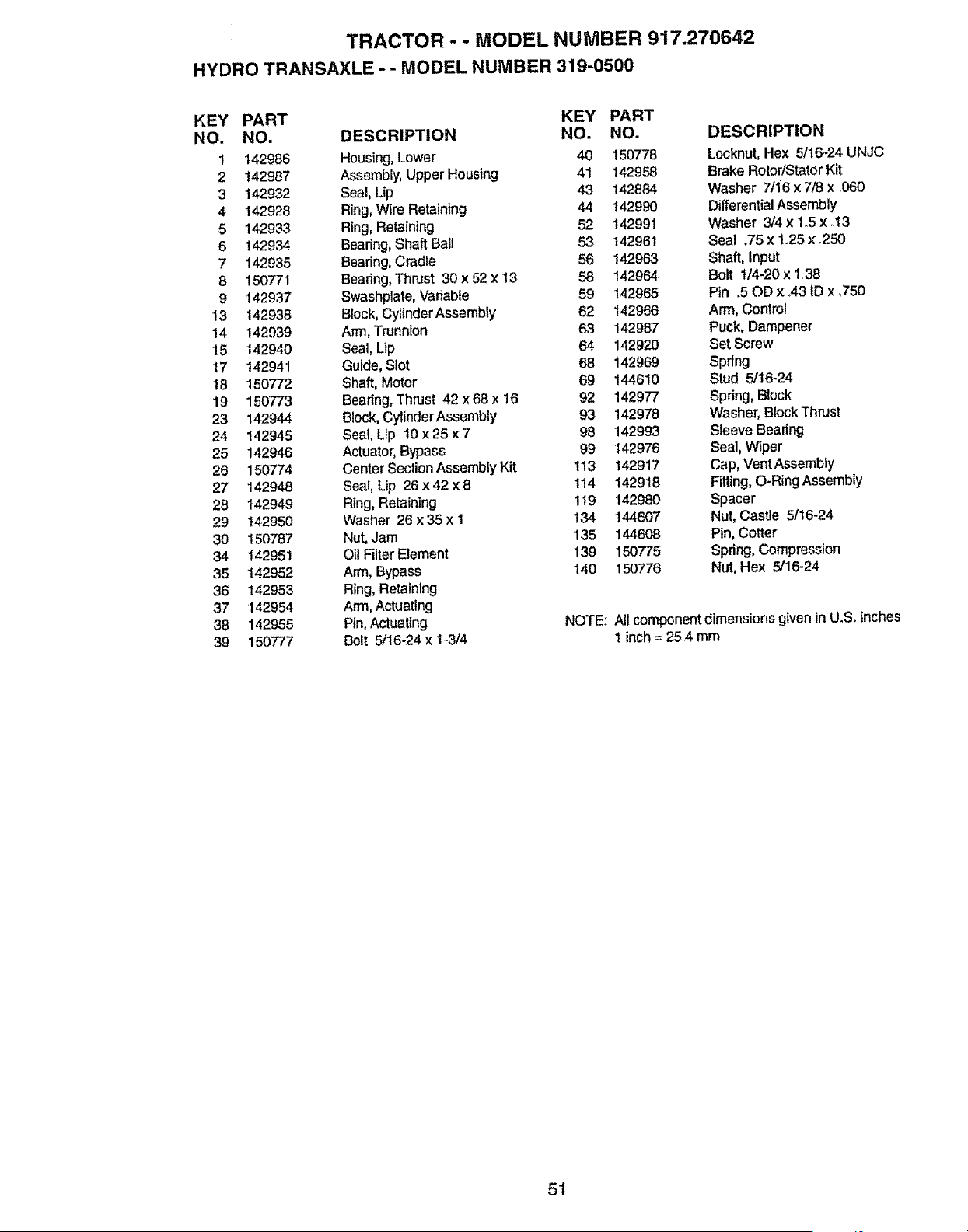
TRACTOR - - MODEL NUMBER 917.270642
HYDRO TRANSAXLE - - MODEL NUMBER 319-0500
KEY PART KEY PART
NO. NO. DESCRIPTION NO. NO.
1 142986 Housing, Lower 40 150776
2 142987 Assembly, Upper Housing 41 142958
3 142932 Seal, Lip 43 142884
4 142928 Ring, Wire Retaining 44 142990
5 142933 Ring, Retaining 52 14299t
6 142934 Bearing, Shaft Ball 53 142961
7 142935 Bearing, Cradle 56 142963
8 150771 Bearing, Thrust 30 x 52 x 13 58 142964
9 142937 Swashpiate, Vadabte 69 142965
13 142938 Block, CylinderAssembly 62 142966
14 142939 Arm, Trunnion 63 142967
15 142940 Seal, Lip 64 142920
17 142941 Guide, Slot 68 142969
18 150772 Shaft, Motor 69 144610
19 150773 Bearing, Thrust 42 x 68 x 16 92 142977
23 142944 Block, CylinderAssembly 93 142976
24 142945 Seal, Lip 10 x 25 x 7 98 142993
25 142946 Acluator, Bypass 99 142976
26 150774 Center Section Assembly Kit 113 142917
27 142948 Seal, Lip 26 x 42 x 8 114 142918
28 142949 Ring, Retaining 119 142980
29 142950 Washer 26 x 35 x I 134 144607
30 150787 Nut, Jam 135 144608
34 142951 Oil Filter Element 139 150775
35 142952 Arm, Bypass 140 150776
36 142953 Ring, Retaining
37 142954 Arm, Actuating
38 142955 Pin, Actuating NOTE:
39 150777 Bolt 5/16-24 x 143/4
DESCRIPTION
Locknut,Hex 5/16_24UNJC
BrakeRotor/StatorKit
Washer 7/16 x 7/8 x .060
DifferentialAssembly
Washer 3/4 x 1_5x .I3
Seal .75 x 1.25 x .250
Shaft, Input
Bolt 1/4-20 x 1,38
Pin .50D x ,43 tD x ,750
Arm, Control
Puck, Dampener
Set Screw
Spring
Stud 5/16-24
Spring,Block
Washer, BlockThrust
Sleeve Bearing
Seal, Wiper
Cap, Vent Assembly
Fitting, O-Ring Assembly
Spacer
Nut, Castle 5/16-24
Pin, Cotter
Spring,Compression
Nut, Hex 5/16-24
All component dimensionsgiven in U.Soinches
1 inch= 25.4 mm
51
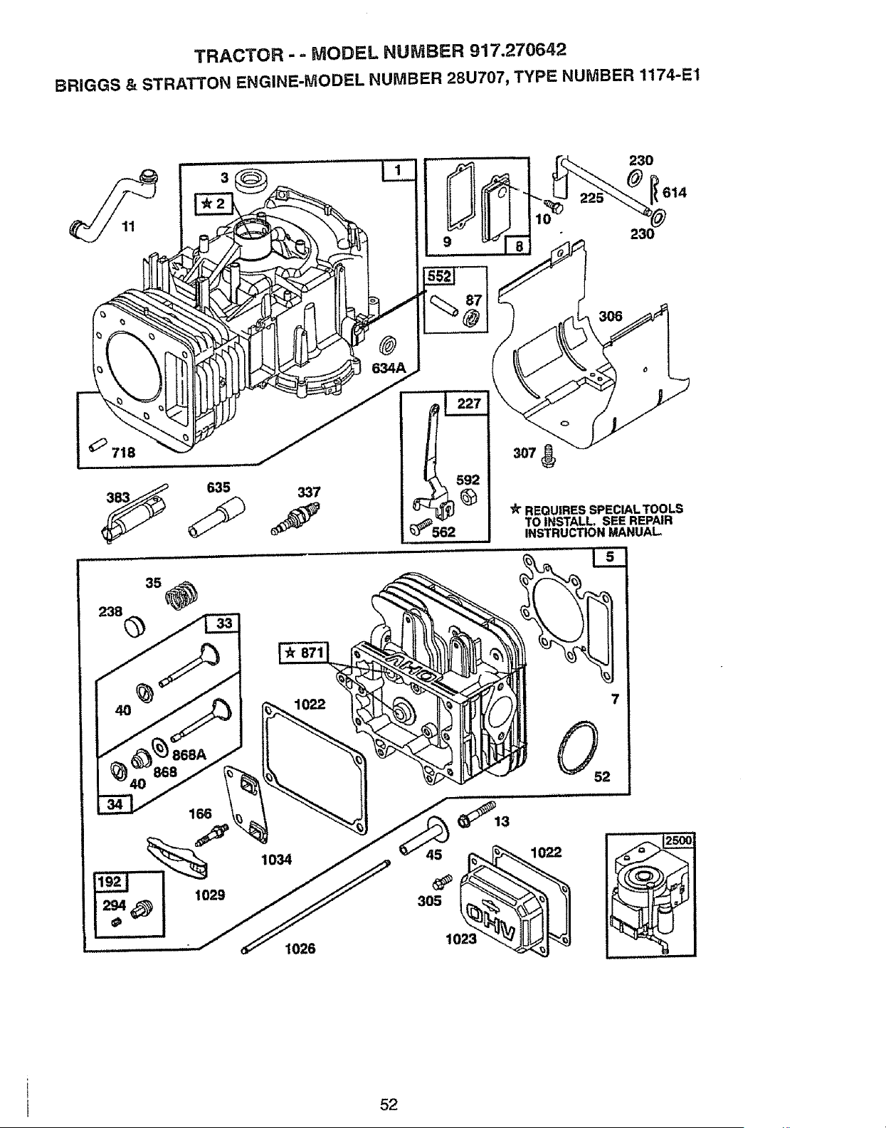
TRACTOR - - f,,/iODF--L NUMBER 917.270642
BRIGGS & STRATTON ENGINE-MODEL NUMBER 28U707, TYPE NUMBER 1174-E1
562
230
614
230
'_ REQUIRES SPECIAL TOOLS
TO INSTALL. SEE REPAIR
INSTRUCTION MANUAL
1026
L
52
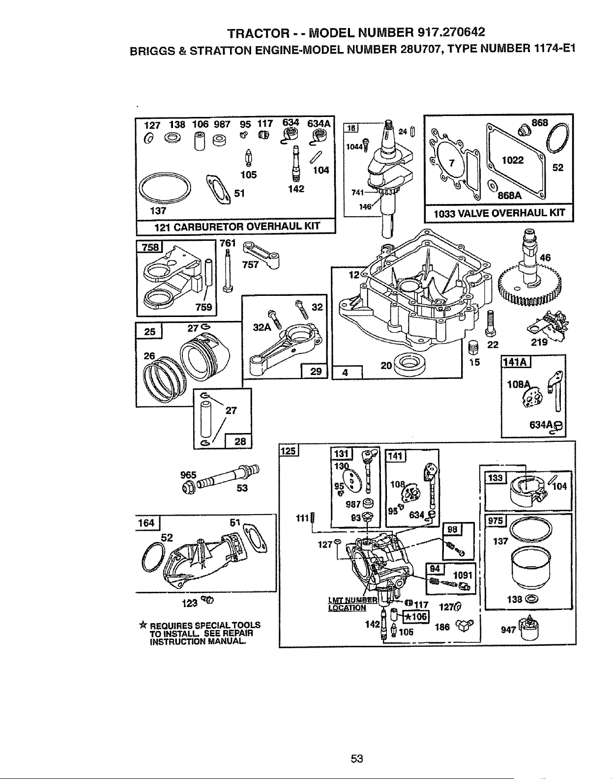
TRACTOR -- MODEL NUMBER 917.270642
BRIGGS & STRATTON ENGINE-MODEL NUMBER 28U707, TYPE NUMBER 1174-E1
127 138 196 987 95 117 634 6,._4A"
51 142
137
121 CARBURETOR OVERHAUL KIT
27_
!
"_ REQUIRES SPECIALTOOLS
TO INSTALL SEE REPAIR
INSTRUCTION MANUAL.
1111
127<
22
e34A_
53
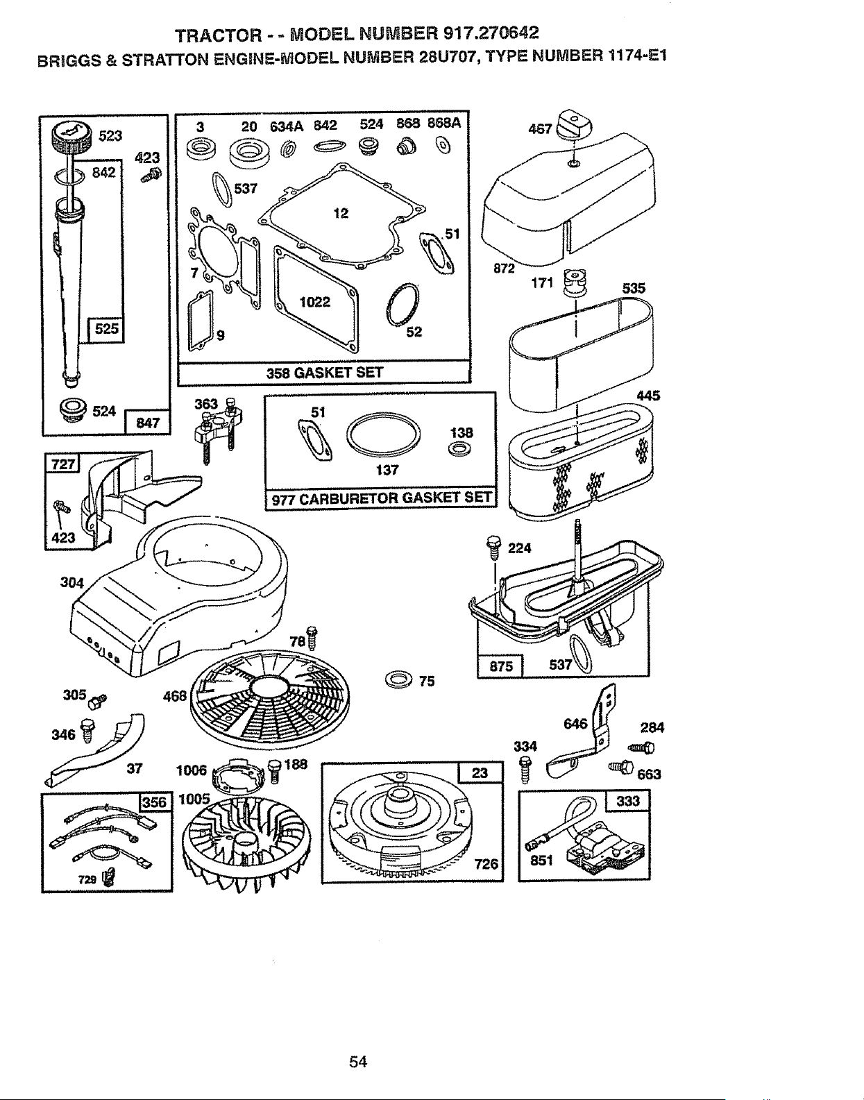
TRACTOR -- MODEL NUMBER 917.270642
BRIGGS & STRATTON ENGeNE-MODEL NUMBER 28U707, TYPE NUMBER 1174-_=1
634A 842 524 868 868A
12
358 GASKET SET
Nl=ll=l
51
137
138
977 CARBURETOR GASKET SET
171 _ 535
224
468
37
54
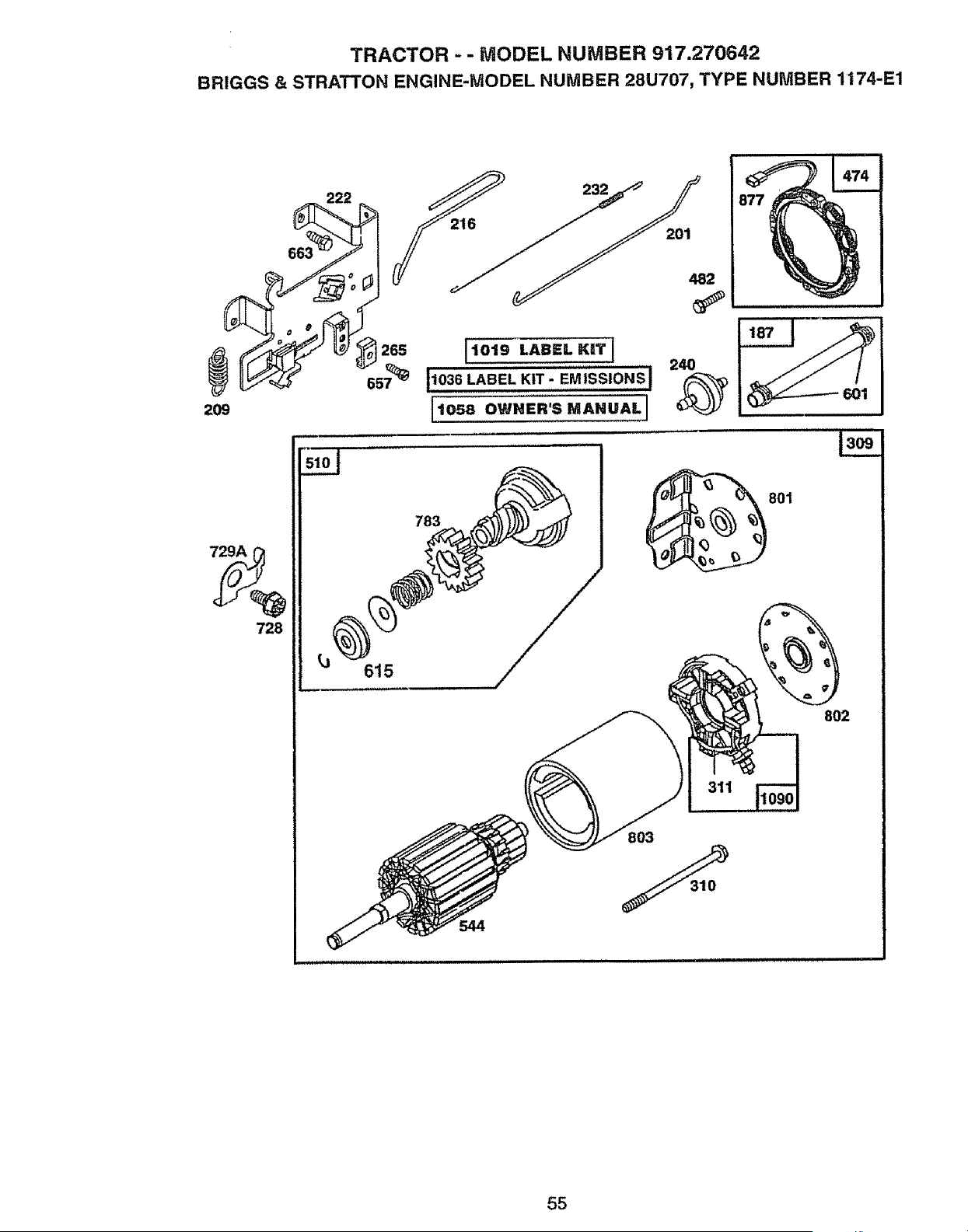
TRACTOR - - MODEL NUMBER 917.27064.2
BRIGGS & STRATTON ENGINE-MODEL NUMBER 28U707, TYPE NUMBER 1174-E1
222
209
201
482
1019 LABEL KIlT i
.............. 240
11036 LABEL KIT- EMJSSiONSl
[t058 OWNER'S MANUAL I
728
783
311
803
615
802
55
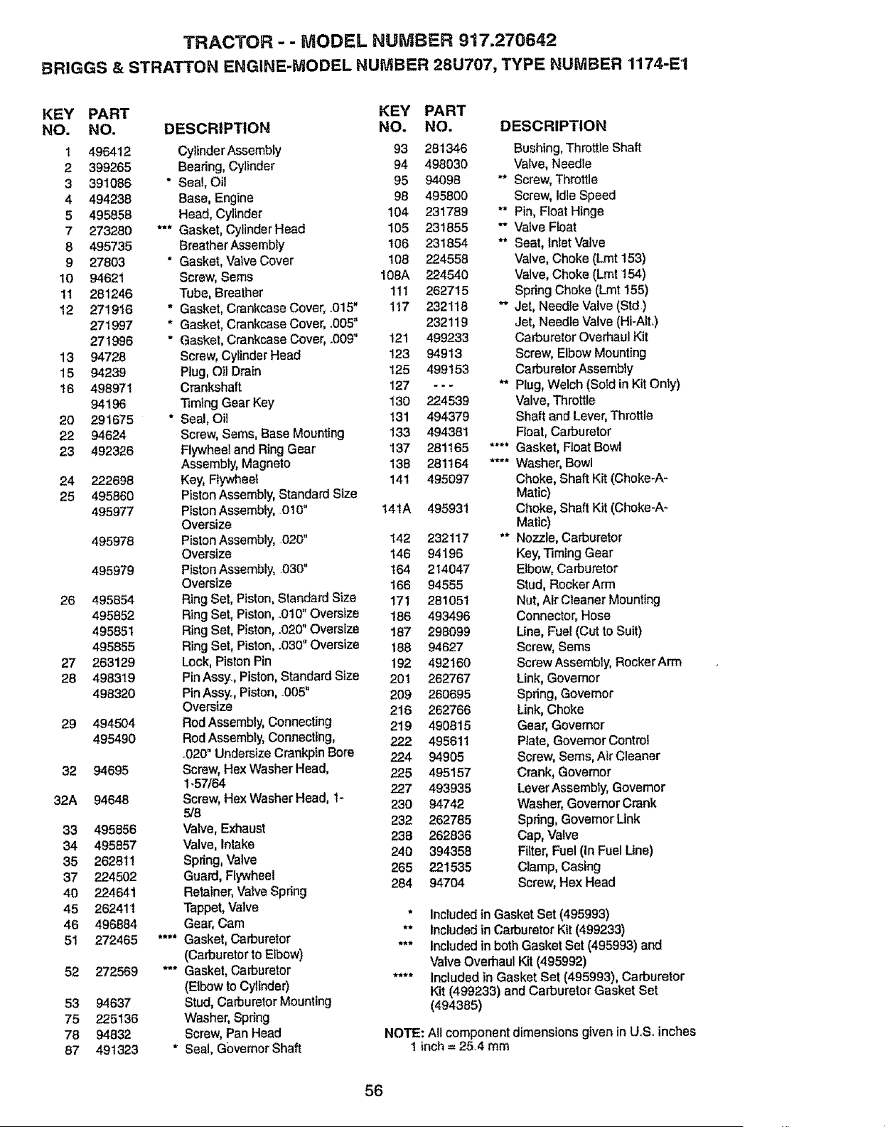
TRACTOR - - MODEL NUMBER 917.270642
BRIGGS & STRATTON ENGINE-MODEL NUMBER 28U707, TYPE NUMBER 1174-E1
KEY PART KEY PART
NO. NO. DESCRIPTION NO, NO, DESCRIPTION
1 496412 Cylinder Assembly 93 281346 Bushing, Throttle Shaft
2 399265 Beadng, Cylinder 94 498030 Valve, Neadle
3 391086 * Seal, Oil 95 94098 ** Screw, Throttle
4 494238 Base, Engine 98 495800 Screw, ldte Speed
5 495858 Head, Cylinder 104 231789 ** Pin, Float Hinge
7 273280 *** Gasket, Cylinder Head I05 231855 ** Valve Roat
8 495735 Breather Assembly 106 231854 ** Seat, Inlet Valve
9 27803 * Gasket, Valve Cover 108 224558 Valve, Choke (Lmt 153)
10 94621 Screw, Sems 108A 224540 Valve, Choke (Lmt 154)
11 281246 Tube, Breather 1tt 262715 Spdng Choke (Lmt 155)
12 271916 " Gasket, Crankcase Cover, .015" 1t7 232118 ** Jet, Needle Valve (Std)
271997 * Gasket, Crankcase Cover, .005" 232119 Jet, Needle Valve (Hi-AlL)
271996 * Gasket, Crankcase Cover, .009" 121 499233 Carburetor Overhaul Kit
13 94728 Screw, Cyllbder Head 123 94913 Screw, Elbow Mounting
15 94239 Plug, Oil Drain 125 499153 CarburetorAssembty
!6 498971 Crankshaft 127 - - - ** Plug, Welch (Sotd in Kit Onty)
94196 Timing Gear Key 130 224539 Valve, Throttle
20 291675 * Seal, Oil t31 494379 Shaft and Lever, Throttle
22 94624 Screw, Sems, Base Mounting 133 494381 Float, Carburetor
23 492326 Flywheel and Ring Gear 137 281165 .... Gasket, Float Bowl
Assembly, Magneto 138 281164 .... Washer, Bowl
24 222698 Key, Ftywheet 141 495097 Choke, Shaft Kit (Choke-A-
25 495860 Piston Assembly, Standard Size Matic)
495977 Piston Assembly, .010" 14tA 495931 Choke, Shaft Kit (Choke-A-
Oversize Matic)
495978 Piston Assembly, 020" 142 232117 ** Nozzle, Carburetor
Oversize t46 94196 Kay, Timing Gear
495979 Piston Assembly, 030" t64 214047 Elbow, Carburetor
Oversize 166 94555 Stud, RockerArrn
26 495854 Ring Set, Piston, Standard Size 17t 281051 Nut, Air Cleaner Mounting
495852 Ring Set, Piston, o010" Oversize t86 493496 Connector, Hose
495851 Ring Set, Piston, .020" Oversize 187 298099 Line, Fuel (Cut to Suit)
495855 Ring Set, Piston, .030" Oversize 188 94627 Screw, Sems
27 263129 Lock, Piston Pin 192 492160 Screw Assembly, RockerArm
28 498319 PinAssy., Piston, Standard Size 201 262767 Link, Governor
498320 Pin Assyo, Piston, .005" 209 260695 Spdng, Governor
Oversize 216 262766 Link, Choke
29 494504 Rod Assembly, Connecting 219 490815 Gear, Governor
495490 Rod Assembly, Connecting, 222 495611 Ptate, GovemorControf
°020" Undersize Crankpin Bore 224 94905 Screw, Sems, Atr Cleaner
32 94695 Screw, Hex Washer Head, 225 495157 Crank, Governor
1-57/64 227 493935 LeverAssembty, Governor
32A 94648 Screw, Hex Washer Head, t- 230 94742 Washer, Governor Crank
5/8
232 262785 Spring, Govemor Link
33 495856 Valve, Exhaust 238 262836 Cap, Valve
34 495857 Valve, Intake 240 394358 Filter, Fuel (In Fuel Line)
35 262811 Spring, Valve
265 221535 Clamp, Casing
37 224502 Guard, Flywheel 284 94704 Screw, Hex Head
40 224641 Retainer, Valve Spdng
45 262411 Tappet, Valve * Included in Gasket Set (495993)
46 496884 Gear, Cam ** Included in Carburetor Kit (499233)
51 272465 .... Gasket, Carburetor *** Included in both Gasket Set (495993) and
(Carburetor to Elbow) Valve Overhaul Kit (495992)
52 272569 *'* Gasket, Carburetor .... Included in Gasket Set (495993), Carburetor
(Elbow to Cylinder) Kit (499233) and Carburetor Gasket Set
53 94637 Stud, Carburetor Mounting (494385)
75 225136 Washer, Spring
78 94632 Screw, Pan Head NOTE: All component dimensions given in UoSoinches
87 491323 * Sea!, Governor Shaft 1 inch = 25A mm
56
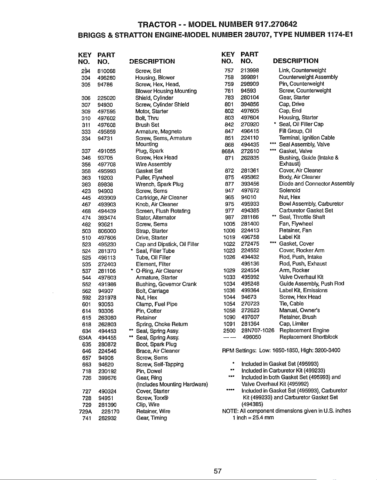
TRACTOR - - MODEL NUMBER 917.270642
BRIGGS & STRATTON ENGINE-MODEL NUMBER 28U707, TYPE NUMBER 1174-E1
KEY PART
NO. NO.
2_. 810068
304 496280
305 94786
306 225020
307 94930
3O9 497595
310 497602
31I 497608
333 495859
334 94731
337 491055
346 93705
356 497708
358 495993
363 t 9203
383 89838
423 94903
445 493909
467 493903
468 494439
474 393474
482 93621
503 806000
510 497606
523 495230
524 281370
525 496113
535 2724O3
537 281106
544 497603
552 49I 986
562 94907
592 23! 978
601 93053
614 93306
615 263080
618 262803
634 494453
634A 494455
635 280872
646 224546
657 94906
663 94620
718 230192
726 399676
727 490324
728 94951
729 281390
729A 225170
741 262932
KEY PART
DESCRIPTION NO. NO. DESCRIPTION
Screw, Set 757 213998 Link, Counterweight
Housing, Blower 758 399891 Counterweight Assembly
Screw, Hex, Head, 759 298909 Pin, Counterweight
Blower Housing Mounting 761 94593 Screw, Counterweight
Shield, Cylinder 783 280104 Gear, Starter
Screw, Cylinder Shield 801 394856 Cap, Ddve
Motor, Starter 802 497605 Cap, End
Bolt, Thru 803 497604 Housing, Starter
Brush Set 842 270920 * Seal, Oil Filler Cap
Armature, Magneto 847 496415 Fill Group, Oil
Screw, Seres, Armature 851 224110 Terminal, Ignition Cable
Mounting 868 494435 *** SealAssembly, Valve
Plug, Spark 868A 272610 *** Gasket, Valve
Screw, Hex Head 871 262835 Bushing, Guide (Intake &
Wire Assembly Exhaust)
Gasket Set 872 281361 Cover, Air Cleaner
Puller, Flywheel 875 495862 Body, Air Cleaner
Wrench, Spark Plug 877 393456 Diode and ConnectorAssembly
Screw, Sems 947 497672 Solenoid
Cartridge, Air Cleaner 965 94010 Nut, Hex
Knob, Air Cleaner 975 495933 Bowl Assembly, Carburetor
Screen, Flush Rotating 977 494385 Carburetor Gasket Set
Stator, Alternator 987 281166 "* Sea!, Throttle Shaft
Screw, Sems !005 281400 Fan, Flywheel
Strap, Slarter 1006 224413 Retainer, Fan
Drive, Starter 1019 496758 Label Kit
Cap and Dipstick, Oil Filler 1022 272475 *** Gasket, Cover
• Seal, FUlerTube 1023 224552 Cover, RockerArm
Tube, Oil Filler 1026 494432 Rod, Push, Intake
Element, Filter 495136 Rod, Push, Exhaust
• O-Ring, Air Cleaner 1029 224554 Arm, Rocker
Armature, Starter 1033 495992 Valve Overhaul Kit
Bushing, Govemor Crank 1034 495248 Guide Assembly, Push Rod
Boff, Carriage 1036 499364 Label Kit, Emissions
Nut, Hex 1044 94673 Screw, Hex Head
Clamp, Fuel Pipe 1054 270723 "lie, Cable
Pin, Cotter 1058 272623 Manual, Owner's
Retainer 1090 497607 Retainer, Brush
Spring, Choke Return 1091 281364 Cap, Lirniter
• * Seal, Spring Assy_ 2500 28N707-1026 Replacement Engine
•* Seal, Spdng Assy. _ _ 496050 Replacement Shortblock
Boot, Spark Plug
Brace, Air Cleaner RPM Settings: Low: 1650-1850, High: 3200-3400
Screw, Sems
Screw, Self*Tapping * Included in Gasket Set (495993)
Pin, Dowel "* Included in Carburetor Kit (499233)
Gear, Ring *** Included in both Gasket Set (495993) and
(Includes Mounting Hardware) Valve Overhaul Kit (495992)
Cover, Starter .... Included in Gasket Set (495993), Carburetor
Screw, Torx_ Kit (499233) and Carburetor Gasket Set
Clip, Wire (494385)
Retainer, Wire NOTE: A!l component dimensions given in U.S. inches
Gear, Timing 1 inch = 25.4 mm
57

58

0
m
<
r_
LU
n
0
IJJ
,,<
0
LL
r.f)
W
n
0
0
Z:
m
0
m
r_
0
W
w
r_
I-.,
LU
r3
r_
r_
J
_,1
0
/
/
/
/
i
I
/
,
/
/
/-
1
1
,<
L,,'_
5g

For the repair or replacement parts you need
delivered directly to your home
Call 7 am - 7 pm, 7 days a week
1=800..366=.PART
(1-800-366-7278)
Para ordenar piezas con entrega a
domicilto - 1-800-659-7084
For in-house major brand repair service
Call 24 hours a day, 7 days a week
1=800=4=REPAIR
(1-800-473-7274)
Para pedir servicio de reparacibn a
domicilio - 1-800-676-5811
For the location of a Sears Parts and
Repair Center in your area
Call 24 hours a day, 7 days a week
1=800=488-1222
For information on purchasing a Sears
Maintenance Agreement or to inquire
about an existing Agreement
Call 9 am - 5 pro, Monday-Saturday
1=800-.827=6655
When requesting service or ordering
parts, always provide the following
information:
oProduct Type • Part Number
• Model Number ° Part Description
8-WAR,
Amenca's Repair Specialists
165376 5.14.98 JH Printed in U.S.A.