
ALEXA Mini LF
Software Update Package 6.0
U S E R M A N U A L
September 10, 2019
ALEXA Mini LF
Software Update Package 6.0
U S E R M A N U A L
September 10, 2019

Imprint 2
Imprint
Copyright
© 2019 Arnold & Richter Cine Technik GmbH & Co. Betriebs KG. All rights reserved. No portions
of this document may be reproduced without prior written consent of Arnold & Richter Cine Technik
GmbH & Co. Betriebs KG. Specifications are subject to change without notice. Errors, omissions, and
modifications excepted.
AMIRA, ALEXA, ALEXA XT, ALEXA SXT, ALEXA LF, ALEXA Mini and ALEXA Mini LF are trademarks
or registered trademarks of Arnold & Richter Cine Technik GmbH & Co. Betriebs KG. All other brands
or products are trademarks or registered trademarks of their respective holders and should be treated
as such.
Original version.
For Further Assistance
Arnold & Richter Cine Technik GmbH & Co. Betriebs KG
Tuerkenstr. 89
D-80799 Munich
Germany
E-mail: [email protected]
www.arri.com/en/technical-service
Document Revision History
Document ID:
Version
6.0
6.0
Release
K10155
K10213
Date
July 15, 2019
September 10, 2019

Contents 3
1 Contents
1 Contents.............................................................................................................................3
2 Disclaimer.......................................................................................................................... 7
3 For Your Safety /
为了您的安全
........................................................................................ 8
3.1 Risk Levels and Alert Symbols /
危险级别和警示标志
..................................................... 8
3.2 Vital Precautions /
重要安全措施
...................................................................................... 9
3.3 Safety Guidelines............................................................................................................10
4 Sensor Related Information /
有关影像传感器的信息
....................................................12
5 Audience and Intended Use.......................................................................................... 14
6 Scope of Delivery and Warranty................................................................................... 15
7 Introduction to the ALEXA Mini LF.............................................................................. 16
8 Camera Layout................................................................................................................ 17
8.1 Camera Rear Connectors...............................................................................................19
8.2 Camera Left and Front Connectors............................................................................... 21
8.3 Media Bay....................................................................................................................... 22
8.4 Product Identification...................................................................................................... 22
9 Camera Support.............................................................................................................. 23
10 Power Supply.................................................................................................................. 26
11 Lens Mounts and Lens Handling..................................................................................28
11.1 LPL Mount and PL-to-LPL Adapter................................................................................28
11.2 Changing a Lens............................................................................................................ 29
11.3 Maximum Lens Mounting Depth.....................................................................................31
11.4 Changing the Lens Mount.............................................................................................. 31
11.5 Lens Data....................................................................................................................... 33
12 Multi Viewfinder MVF-2.................................................................................................. 35
12.1 Flip-out Monitor............................................................................................................... 37
12.2 MVF-2 Cables................................................................................................................. 38
13 Menu Operation...............................................................................................................39
13.1 HOME Screen.................................................................................................................40
13.2 Using the On-screen Keyboard......................................................................................43
13.3 Working with Lists and Import of Files........................................................................... 44
13.4 Function Button FN.........................................................................................................46
13.5 User Storage Handling................................................................................................... 47
13.6 Info Screens....................................................................................................................48
13.7 Alerts Screen.................................................................................................................. 50

Contents 4
14 Main Parameters............................................................................................................. 51
14.1 Project Settings...............................................................................................................51
14.2 Sensor Frame Rate........................................................................................................ 52
14.3 Shutter.............................................................................................................................53
14.4 Exposure Index...............................................................................................................53
14.5 ND Filter..........................................................................................................................54
14.6 White Balance.................................................................................................................55
14.7 Timecode.........................................................................................................................56
15 Look Settings.................................................................................................................. 59
15.1 Processing and Color Spaces........................................................................................61
16 Recording.........................................................................................................................63
16.1 Recording Media Handling............................................................................................. 63
16.1.1 Erase of Recording Media............................................................................................64
16.1.2 Remaining Recording Capacity and Media Information............................................... 65
16.2 Starting Recording via REC button................................................................................ 65
16.3 Recording Format........................................................................................................... 65
16.4 Recording Resolution..................................................................................................... 67
16.5 Audio Recording............................................................................................................. 68
16.6 Rec Beeper and Tally Settings.......................................................................................70
16.7 File Naming Scheme...................................................................................................... 70
16.8 Data Handling................................................................................................................. 71
17 Playback...........................................................................................................................72
18 Monitoring........................................................................................................................74
18.1 Status Information and Status Overlays.........................................................................74
18.1.1 Flip-out Monitor Status Bar.......................................................................................... 77
18.1.2 Overlay Menu............................................................................................................... 77
18.2 Surround View................................................................................................................ 78
18.3 Magnification................................................................................................................... 79
18.4 Frame Lines.................................................................................................................... 80
18.5 Anamorphic Desqueeze................................................................................................. 81
18.6 Exposure Tools............................................................................................................... 82
18.6.1 False Color................................................................................................................... 82
18.6.2 Zebra.............................................................................................................................84
18.7 Focus Tools.....................................................................................................................84
18.7.1 Peaking......................................................................................................................... 84
18.7.2 Zoom............................................................................................................................. 85
18.8 SDI Configuration........................................................................................................... 86
18.9 EVF/Monitor Settings...................................................................................................... 88
18.10 Color Bars....................................................................................................................... 89

Contents 5
19 Synchronization.............................................................................................................. 90
19.1 EXT Sync........................................................................................................................ 90
19.2 Genlock Synchronization................................................................................................ 93
19.3 Timecode Synchronization..............................................................................................93
20 Sensor Settings...............................................................................................................94
20.1 Noise Reduction............................................................................................................. 94
20.2 Mirroring the Sensor Image............................................................................................94
20.3 User Pixel Masking.........................................................................................................95
21 System Settings.............................................................................................................. 97
21.1 Language Setting............................................................................................................97
21.2 System Time and Date...................................................................................................97
21.3 Button and Display Settings........................................................................................... 97
21.4 Fan Settings....................................................................................................................97
21.5 Battery Warning.............................................................................................................. 97
21.6 Lens Mount Settings.......................................................................................................98
21.7 Network and WiFi Settings............................................................................................. 98
21.8 Reset of Electronic Horizon..........................................................................................101
21.9 Camera Update............................................................................................................ 101
21.9.1 Update of Camera Software.......................................................................................101
21.9.2 Update of Camera Components................................................................................ 102
21.9.3 Update of LBUS Devices........................................................................................... 102
22 User Setups................................................................................................................... 103
22.1 User Setup Parameter Blocks......................................................................................104
23 User Buttons................................................................................................................. 107
23.1 List of User Button Functions.......................................................................................108
24 Metadata.........................................................................................................................111
25 Electronic Control System (ECS)................................................................................113
25.1 White Radio Configuration............................................................................................113
25.2 Lens Motors.................................................................................................................. 114
25.3 Lens Data..................................................................................................................... 115
25.3.1 Adding Lens Tables (LDA)......................................................................................... 116
26 Remote Control............................................................................................................. 117
26.1 Wireless Control Unit WCU-4.......................................................................................117
26.2 Web Remote (Beta Version).........................................................................................117
26.3 Camera Access Protocol (CAP)................................................................................... 118

Contents 6
27 Transvideo Starlite HD5-ARRI Monitor.......................................................................119
28 Appendix........................................................................................................................ 121
28.1 Companion Tools.......................................................................................................... 121
28.2 Connector Pin-Outs...................................................................................................... 124
28.3 Technical Data.............................................................................................................. 127
28.4 Declarations of Conformity........................................................................................... 130
28.5 Dimensional Drawings.................................................................................................. 134

Disclaimer 7
2 Disclaimer
Before using the products described in this manual be sure to read and understand all respective
instruction.
The ARRI ALEXA Mini LF is only available to commercial customers. The customer grants by utilization
that the ARRI ALEXA Mini LF or other components of the system are deployed for commercial use.
Otherwise the customer has the obligation to contact ARRI preceding the utilization.
While ARRI endeavors to enhance the quality, reliability and safety of their products, customers agree
and acknowledge that the possibility of defects thereof cannot be eliminated entirely. To minimize
risk of damage to property or injury (including death) to persons arising from defects in the products,
customers must incorporate sufficient safety measures in their work with the system and have to heed
the stated canonic use.
ARRI or its subsidiaries do not assume any responsibility for incurred losses due to improper handling
or configuration of the camera or other system components, due to sensor contamination, occurrence
of dead or defective pixels, defective signal connections or incompatibilities with third party recording
devices.
ARRI assumes no responsibility for any errors that may appear in this document. The information is
subject to change without notice.
For product specification changes since this manual was published, refer to the latest publications of
ARRI data sheets or data books, etc., for the most up-to-date specifications. Not all products and/or
types are available in every country. Please check with an ARRI sales representative for availability and
additional information.
Neither ARRI nor its subsidiaries assume any liability for infringement of patents, copyrights or other
intellectual property rights of third parties by or arising from the use of ARRI products or any other
liability arising from the use of such products. No license, express, implied or otherwise, is granted
under any patents, copyrights or other intellectual property right of ARRI or others.
ARRI or its subsidiaries expressly exclude any liability, warranty, demand or other obligation for any
claim, representation, or cause, or action, or whatsoever, express or implied, whether in contract or tort,
including negligence, or incorporated in terms and conditions, whether by statue, law or otherwise. In
no event shall ARRI or its subsidiaries be liable for or have a remedy for recovery of any special, direct,
indirect, incidental, or consequential damages, including, but not limited to lost profits, lost savings, lost
revenues or economic loss of any kind or for any claim by third party, downtime, good will, damage to or
replacement of equipment or property, any cost or recovering of any material or goods associated with
the assembly or use of our products, or any other damages or injury of the persons and so on or under
any other legal theory.
In the case one or all of the foregoing clauses are not allowed by applicable law, the fullest extent
permissible clauses by applicable law are validated.
ARRI is a registered trademark of
Arnold & Richter Cine Technik GmbH & Co Betriebs KG.
Apple ProRes 422 HQ, Apple ProRes 4444, Apple ProRes 4444 XQ, and the
ProRes logo are trademarks or registered trademarks of Apple Computer, Inc., used
under license therefrom.
For Your Safety /
为了您的安全
8
3 For Your Safety /
为了您的安全
Before use, please ensure that all users read, understand and follow the instructions in this document
fully.
使用前,请确保所有的用户都已经阅读、理解,并遵循本文档内的操作说明。
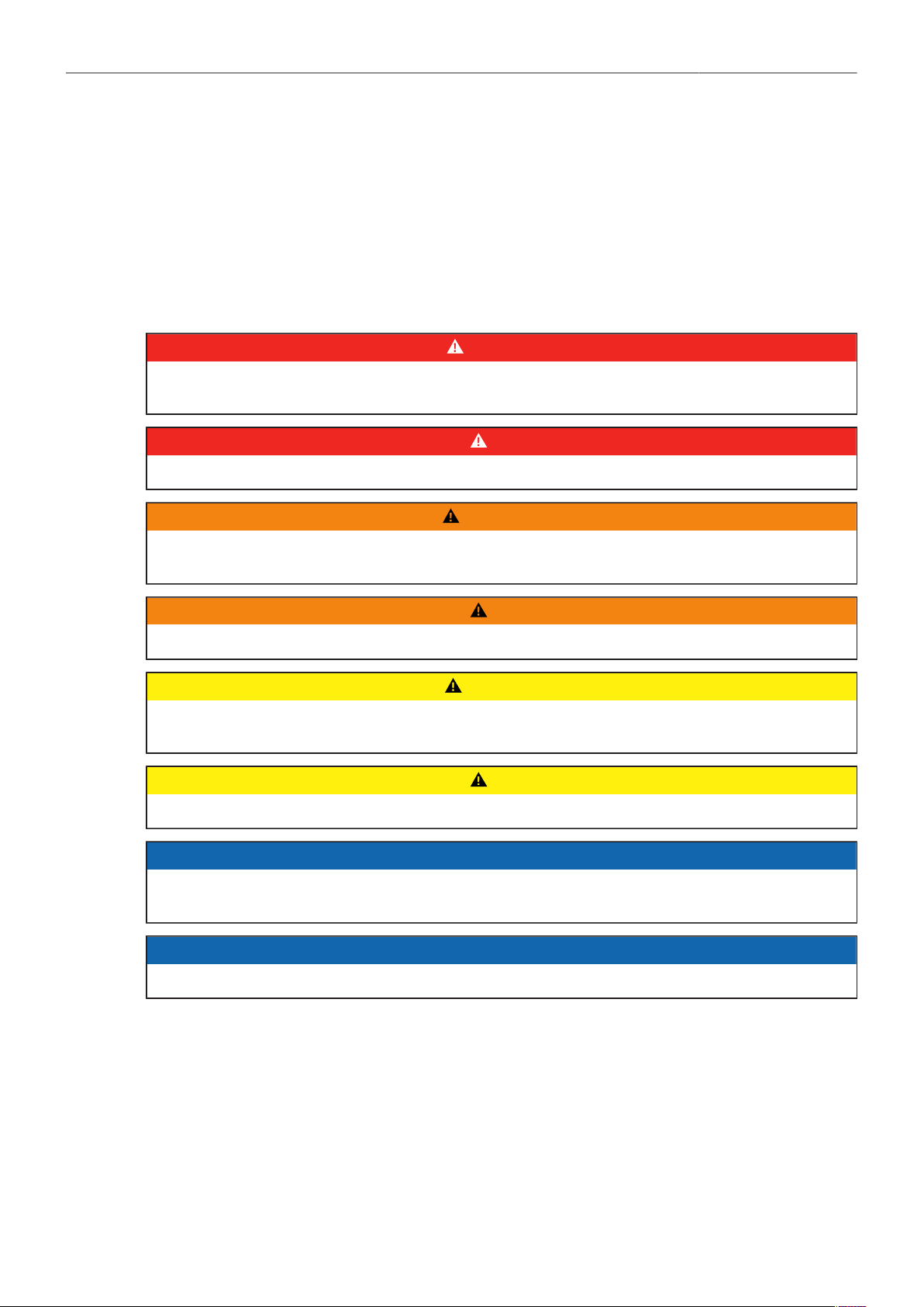
3.1 Risk Levels and Alert Symbols /
危险级别和警示标志
Safety warnings, safety alert symbols, and signal words in these instructions indicate different risk
levels:
本文档内的安全警告、安全警示标志和标识词语指示不同的危险级别:
DANGER!
DANGER indicates an imminent hazardous situation which, if not avoided, will result in death or
serious injury.
危险
危险表示危急、有危害的情景,若不防范,则会导致死亡或严重的伤害。
WARNING!
WARNING indicates a potentially hazardous situation which, if not avoided, may result in death or
serious injury.
警告
警告表示有潜在危害的情景,若不防范,则可能会导致死亡或严重的伤害。
CAUTION!
CAUTION indicates a potentially hazardous situation which, if not avoided, may result in minor or
moderate injury.
小心
小心表示有潜在危害的情景,若不防范,则可能会导致中等或较轻的伤害。
NOTICE
NOTICE explains practices not related to physical injury. No safety alert symbol appears with this
signal word.
提示
注意表示此行为不会导致人身伤害。因此此标识词语中不含警告标志。
Note: Provides additional information to clarify or simplify a procedure.
注:注意中会提供用于解释或简化工作的额外信息。

For Your Safety /
为了您的安全
9
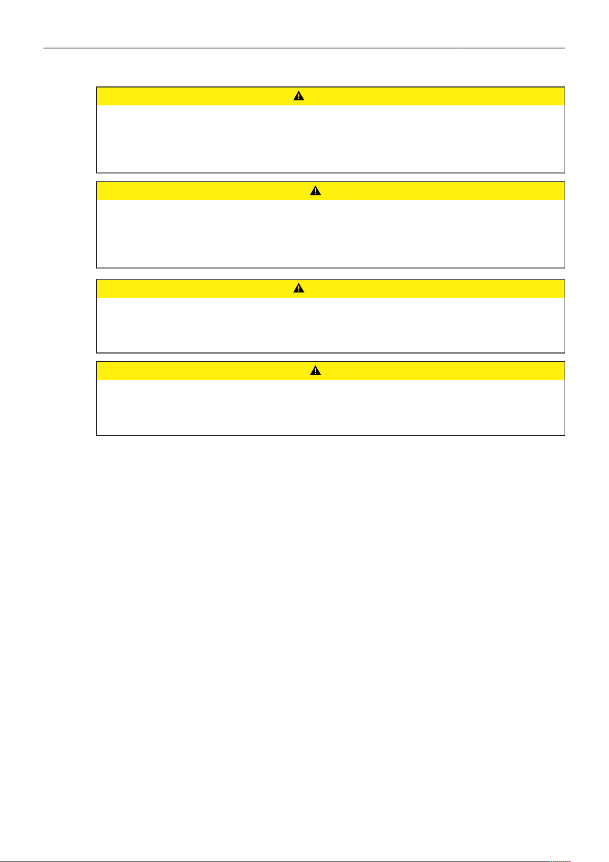
3.2 Vital Precautions /
重要安全措施
DANGER!
High voltage! Risk of electric shock and fire!
Short-circuits may entail lethal damage!
Before use, read and follow all valid instructions.
Use solely and exclusively as described in the instructions.
Never open. Never insert objects.
For operation, always use a power source as indicated in the instructions.
Always unplug the power cable by gripping the power plug, not the cable.
Never try to repair. All repair work should be done by a qualified ARRI Service Center.
Never remove or deactivate any safety equipment (incl. warning stickers or paint-marked screws).
Always protect from moisture, cold, heat, dirt, vibration, shock, or aggressive substances.
Never cover any fan openings.
危险
高电压!有触电或起火风险!
短路将引起致命危险。
使用之前,请仔细阅读所有未过期的使用说明,并严格遵循。
切勿打开机身。切入插入任何物体。
操作时,请务必使用说明中指出的电源。
断开电源时请握住电源插头,而不是电线。
切勿尝试自行维修。所有的维修工作必须由具备资质的
ARRI
维修中心进行。
切勿移除或毁坏任何安全设施(例如警告贴纸或涂漆标示的螺丝)。
务必避免潮湿、寒冷、炎热、多尘、震动、冲击或严酷的使用环境。
切勿覆盖任何风扇开口。
For Your Safety /
为了您的安全
10
CAUTION!
Condensation! Risk of electric shock and fire!
Condensation may form on the sensor and electrical connections when exposing the camera to
sudden changes of temperature or humidity!
To avoid injury and damage, never operate the camera when condensation occurs.
小心
冷凝!有触电或火灾风险!
当将摄影机暴露于温度或湿度迅速变化的环境中时,影像传感器和电子部件连接处可能会产
为了您的
安全
6
生的冷凝。
为了避免受伤或设备损坏,在冷凝发生时切勿操作摄影机。
CAUTION!
Heavy weight! Risk of injury and damage!
If placed on an unstable surface, the camera can fall and cause serious harm!
Always place the camera on proper support devices. Safely attach it as described in the instructions.
小心
设备重量较大!有受伤或设备损坏风险!
若安置于不稳定的位置,则摄影机可能会掉落,并造成严重的伤害。
务必将摄影机安装于适当的支撑设备上。请按照说明中所描述的方法来安全地安装摄影机。
3.3 Safety Guidelines
General Safety Guidelines
► Always follow these guidelines to ensure against injury to yourself or others and damage to the
system or other objects.
► Assembly and initial operation should be carried out only by staff familiar with the system.
► This safety information is in addition to the product specific operating instructions in general and
must be strictly observed for safety reasons.
► Read and understand all safety and operating instructions before you operate or install the system.
► Retain all safety and operating instructions for future reference.
► Heed all warnings on the system and in the safety and operating instructions before you operate or
install the system. Follow all installation and operating instructions.
► Do not use accessories or attachments that are not recommended by ARRI, as they may cause
hazards and invalidate the warranty.
► Do not attempt to repair any part of the system! Repairs must only be carried out by authorized
ARRI Service Centers.
► Only use the tools, materials and procedures recommended in this document. For the correct use of
other equipment, see the manufacturer's instructions.

For Your Safety /
为了您的安全
11
Specific Safety Guidelines
► Do not remove any safety measures from the system.
► Do not operate the system in areas with humidity above operating levels or expose it to water or
moisture.
► Do not subject the system to severe shocks.
► Do not cover the camera fan openings.
► During extended operation, high data rates and/or operation at high ambient temperatures, the
camera's surfaces and especially the area around the fan outlet can get hot. Use caution and never
cover, obstruct or block the fan inlet or outlet while the camera is powered.
► Direct sunlight can result in camera housing temperatures above 60 °C (140 °F). At ambient
temperatures above 25 °C (77 °F), protect the camera from direct sunlight.
► Do not point the camera sensor into direct sunlight, very bright light sources or high energy light
sources (e.g. laser beams). This may cause permanent damage to the camera image sensor.
► Do not place the system on an unstable trolley/hand truck, stand, tripod, bracket, table or any other
unstable support device. The system may fall, causing serious personal injury and damage to the
system or other objects.
► Never insert objects of any kind into any part of the system if not clearly qualified for the task in the
manual, as objects may touch dangerous voltage points or short out parts. This could cause fire or
electrical shock.
► Do not remove any stickers or paint marked screws.
► When no lens is attached to the camera, immediately place the protective cap on the lens mount to
avoid contamination of the sensor cover glass.
► If the sensor cover glass has been contaminated by solid dirt or grease, special optical cleaning kits
should be used for dirt removal under very high care. If the contamination cannot be removed, the
camera should be taken to an ARRI service center for cleaning.
► Clean optical lens surfaces only with a lens brush or a clean lens cloth. In cases of solid dirt or
grease, moisten a lens cloth with pure alcohol. Discard contaminated lens cloth after use. Never
attempt to clean a lens brush with your fingers.
► Do not use solvents for cleaning.
► Never use Acetone to clean optical surfaces.
► The use of Methanol to clean optical surfaces is not recommended.
► Never use cans with compressed air to blow off dust. This can severely damage optical elements.

Sensor Related Information /
有关影像传感器的信息
12
4 Sensor Related Information /
有关影像传感器的信息
Single Frame Spots of Various Shape – also known as “Digital Dust” or “White Flecks”
Natural and/or artificial radiation may cause a “false exposure” on the image sensor. The shape of
these spots may vary from dots to lines or other, sometimes irregular shapes. These spots occur in
random locations of the image, last only for a single frame and are more visible in dark images. This is
a principle issue of all image sensors and not a malfunction.
单帧画面出现斑点,可能是多种形状
——
也被称为“数字尘埃”或“白斑”
自然和/或人工的辐射可能会引起影像传感器的非正常曝光。这些斑点的形状可能是点状、线状或其他不
规则形状。
这些点可能会随机出现在画面的任何地方,仅持续一帧,并在画面暗部更易显现。这是影像传感器的工
作原理导致的,并非故障。
Flicker
Some light sources (i.e. discharge tubes or LEDs) may cause an interference with sensor exposure.
This may result in image flickering or “bands” of different brightness moving up or down the image.
Please note that at higher frame rates (100 fps in 50Hz countries, 120 fps in 60Hz countries) even
tungsten light may flicker. A short recording and playback will show this flicker.
For information on how to reduce flicker when filming a monitor please see Setting a Shutter Value.
频闪
有些光源(例如灯管或
LED
灯)可能会引起对影像传感器曝光的干扰。这会导致画面频闪,或者在画面
里不同亮度、上下运动的条纹。
请注意在某些高帧率下(在
50Hz
国家拍摄
100
fps,在
60Hz
国家拍摄
120
fps),甚至钨丝灯也会发生频
闪。拍摄并回放一个短视频可以检查这种频闪。
Rolling Shutter
Due to the rolling shutter design principle of the sensor the following effects can be observed in certain
situations:
Skewed/slanted vertical lines: fast panning or fast-moving objects may result in vertical structures
to appear "skewed/slanted”. The intensity of the effect depends on the relative speed of panning/
object.
Partial exposure: very short light effects (i.e. a photographer’s flash or strobe light) may result in the
upper part of the image showing the light effect whereas the lower part does not or vice versa.
滚动快门
由于影像传感器的滚动快门工作原理,某些特定场合下会出现以下现象:
歪曲/倾斜的垂直线条:快速横摇或快速移动的物体会导致垂直线条呈现出“歪曲/倾斜”的状态。其
程度取决对横摇/物体运动的相对速度。
不完整曝光:非常短的灯光效果(例如照相机闪光灯或频闪灯)会导致仅有画面的上半部分被照明而
下半部分未被照明,反之亦然。
"Black Sun"
Very bright lights (i.e. the sun, or a photographer’s flash) may result in a black/magenta spot. Note:
pointing the camera directly into the sun may damage the sensor.
“黑太阳”
非常明亮的光源(例如太阳,或照相机闪光灯)可能会成为黑色/洋红色的斑点。注意:将摄影机直接对
准太阳可能会损坏影像传感器。

Sensor Related Information /
有关影像传感器的信息
13
Stuck Pixels at Long Exposure Times
At longer exposure times (longer than the standard 1/50th of a second), stuck pixels may become
visible in darker image areas. The longer the exposure time the more pixels will be affected. When
using exposure times longer than 1/24th of a second, carefully check your image whether the quality
meets your requirements.
长曝光时间的驻留像素
在曝光时间较长时(比常规的
1/50
秒更长),画面中较暗的区域可能会出现驻留像素。
曝光时间越长,这些像素会变得越多。当曝光时间长于
1/24
秒时,请仔细检查画面是否符合您的要求。
Stitching with ALEXA Mini LF
The ALEXA Mini LF sensor consists of a large sensor structure that is created by exposing two Super
35 sensor structures side by side onto a silicon wafer. This process is, somewhat misleadingly, called
“stitching”. As is common with stitched large format sensors in our industry, in rare situations it is
possible to notice the boundary between the left and right image halves.
ALEXA Mini LF
的画面接合
ALEXA Mini LF
的影像传感器采用了大型传感器的结构,即在一块硅晶圆上并排连续曝光两个
Super35
尺
寸的传感器。这种处理方式叫做“接合”,尽管该名称可能会导致误解。
在我们的行业中,接合是大型传感器常见的组成方式。在极其偶然的情况下,画面左右两部分的边界线
可能会被观察到。

Audience and Intended Use 14
5 Audience and Intended Use
The ALEXA Mini LF is a large format digital camera solely and exclusively for recording images at
various resolutions suitable for a variety of distribution formats:
Apple ProRes 422 HQ, Apple ProRes 4444, Apple ProRes 4444 XQ and ARRIRAW codec
Rec 709 and Rec 2020 encoding (through use of look files), Log C or ARRIRAW encoding
Codex Compact Drive recording
Up to 90 fps with full image quality
Large format CMOS sensor
MVF-2 with OLED eyepiece and flip-out monitor for both live view and user interface access
Small and lightweight built for high mobility and special applications
How To Use This Manual
All directions are given from a camera operator's point of view. For example, camera right side refers to
the right side of the camera when standing behind the camera and operating it in a normal fashion.
Connectors are written in all capital letters, for example SDI 1.
Menu paths are written in italic typeface, with menu and home in capital letters, for example MENU >
Recording or HOME > FPS.
Buttons are written in italic typeface capital letters, for example PLAY button.
The appendix at the back of the manual contains useful reference material including ALEXA Mini LF
technical data, connector pin-out diagrams, alert message explanations and dimensional drawings.
NOTICE
The product is solely and exclusively available for commercial costumers and shall be used by
skilled personnel only. Every user should be trained according to ARRI guidelines.
Use the product only for the purpose described in this document. Always follow the valid instructions
and system requirements for all equipment involved.
Strengthen Your Knowledge and Get Trained
The ARRI Academy courses provide unrivalled insights into the full possibilities of working with ARRI
camera systems, lenses, lights and accessories.
To learn more, please visit http://arri.com/academy.

Scope of Delivery and Warranty 15
6 Scope of Delivery and Warranty
Delivery
On delivery, please check if package and content are intact. Never accept a damaged/incomplete
delivery. A complete delivery includes:
ALEXA Mini LF camera
Lens mount according to order
White Radio Antenna
WiFi Antenna
USB memory stick
3.0 mm Allen key
Original packaging incl. drying agent
NOTICE
Product and packaging contain recyclable materials. Always store, ship and dispose according to
local regulations.
ARRI is not liable for consequences from inadequate storage, shipment or disposal.
ARRI offers an increasing variety of product bundles and additional accessories.
For details, please consult our website or your local ARRI Service Partner.
Warranty
For scope of warranty, please ask your local ARRI Service Partner. ARRI is not liable for consequences
from inadequate shipment, improper use or third-party products.

Introduction to the ALEXA Mini LF 16
7 Introduction to the ALEXA Mini LF
The ALEXA Mini LF (Large Format) camera is part of a complete large-format system that meets and
exceeds modern production requirements. Based around a large-format 4.5K version of the ALEXA
Mini sensor, the system comprises the ALEXA LF camera, ALEXA Mini LF camera, ARRI Signature
Prime lenses, LPL lens mount and PL adapter. These system elements have been designed to take the
fullest advantage of the enlarged sensor, while also offering maximum compatibility with existing lenses,
accessories and workflows.
Featuring a sensor slightly larger than full frame, ALEXA Mini LF records native 4.5K with ARRI’s best
overall image quality. This allows filmmakers to explore an immersive large-format aesthetic while
retaining the sensor’s proven suitability for HDR and WCG workflows. Versatile recording formats,
including efficient ProRes and uncompressed ARRIRAW up to 60 fps, provide unprecedented creative
freedom.
ALEXA LF and ALEXA Mini LF have the biggest sensor area of any cinema camera on the market,
second only to ARRI Rental’s ALEXA 65. Maintaining the ALEXA family’s optimal pixel size for highest
overall image quality results in a 4448 x 3096 picture, which can be recorded in full using the LF
Open Gate recording resolution. An LF 16:9 sensor mode maximizes lens options while meeting 4K
deliverable standards, and an LF 2.39:1 recording resolution offers a cinematic widescreen image.
All recording resolutions offer true 800 ASA sensitivity as well as reduced noise, providing the perfect
canvas for modern, subtle lighting techniques.
A crucial element of the system is the LPL lens mount, with dimensions optimized for large format
sensors. A wider diameter and shorter flange focal depth allow the ARRI Signature Primes and
all future large format lenses to be small and lightweight with a fast T-stop and pleasing bokeh, a
combination of features that would not be possible within the confines of the PL lens mount. The LPL
mount is also available for other ARRI cameras such as the ALEXA Mini, ALEXA SXT or AMIRA so the
ARRI Signature Primes can be used for large format and Super 35. In addition, the LPL mount is being
licensed to other lens and camera manufacturers, creating a new universal standard.
Although camera, lens mount and lenses are new, compatibility with existing PL mount lenses and
ALEXA Mini accessories is a cornerstone of the system's design. A PL-to-LPL adapter offers full
backwards compatibility with all PL mount lenses, be they Super 35 or full frame. The PL-to-LPL
adapter clips securely into the LPL lens mount without tools, so crews can rapidly switch between PL
and LPL lenses on set, offering an unlimited lens choice to the cinematographer. Since the ALEXA Mini
LF is based on the proven, robust ALEXA Mini camera design, most existing ALEXA Mini accessories
will work right out of the box.
ALEXA Mini LF offers the same proven, versatile workflows as other ALEXA cameras. Recording at
various resolutions is possible in uncompressed, unencrypted ARRIRAW up to 60 fps or in fast, efficient
Apple ProRes up to 90 fps. Lens metadata can be recorded from LDS-1, LDS-2 or Cooke /i capable
lenses. Existing ARRI Look Files (ALF-2) can be used with ALEXA Mini LF and the entire range of
ARRI workflow software tools has been reworked to support ALEXA large-format images.
Camera Layout 17
8 Camera Layout
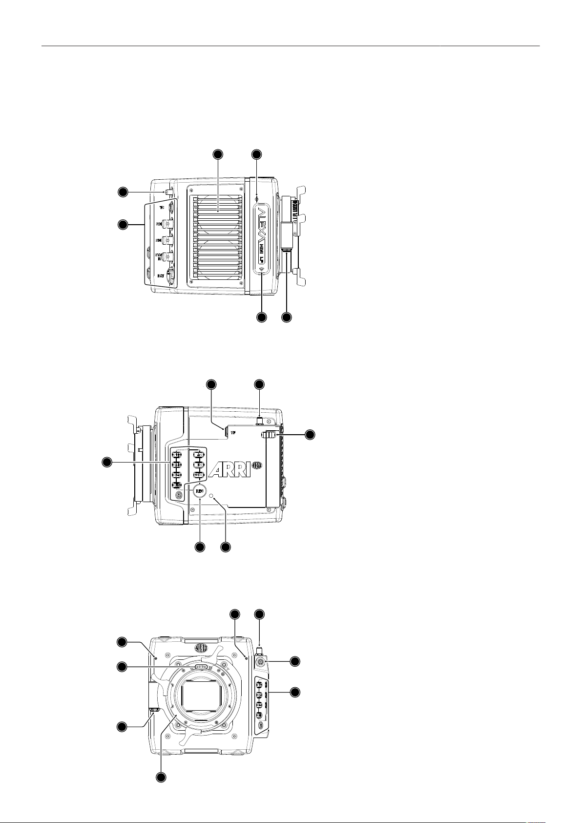
Camera Right
4
6
5
3
2
1
1
Rear Connectors
2
Radio Antenna Connector
3
Fan Intake
4
Sensor Plane Marking
5
LBUS Connector (on Lens Mount)
6
Integrated WiFi Antenna
Camera Left
6
5
4
3
1
2
1
Record Button
2
Camera Buttons
3
VF Viewfinder Connector
4
WiFi Antenna Connector
5
Media Door Release
6
Camera Status LED
Camera Front
1
2
6
8
3
4
5
7
1
LPL Lens Mount
2
LBUS Connector (on Lens Mount)
3
Lens Mount Contacts
4
Built-in Microphone (right)
5
Built-in Microphone (left)
6
WiFi Antenna Connector
7
VF Viewfinder Connector
8
Camera Buttons
Camera Layout 18
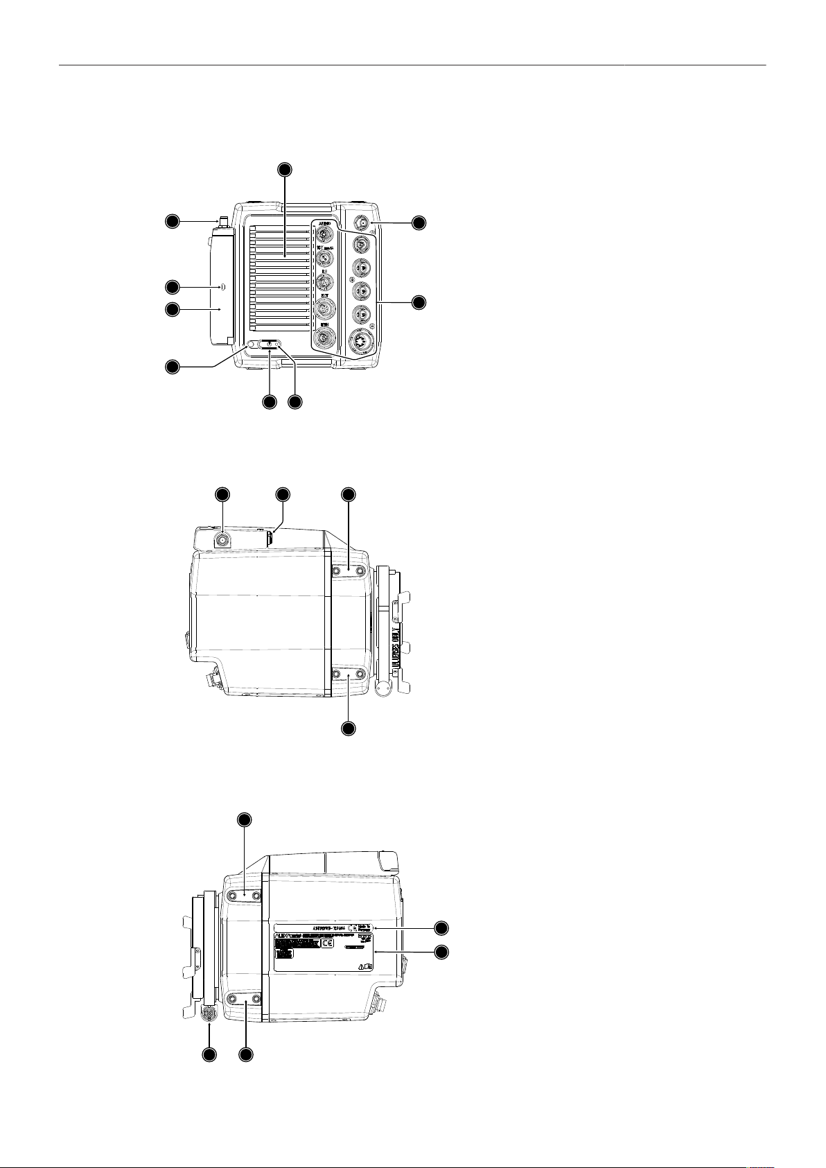
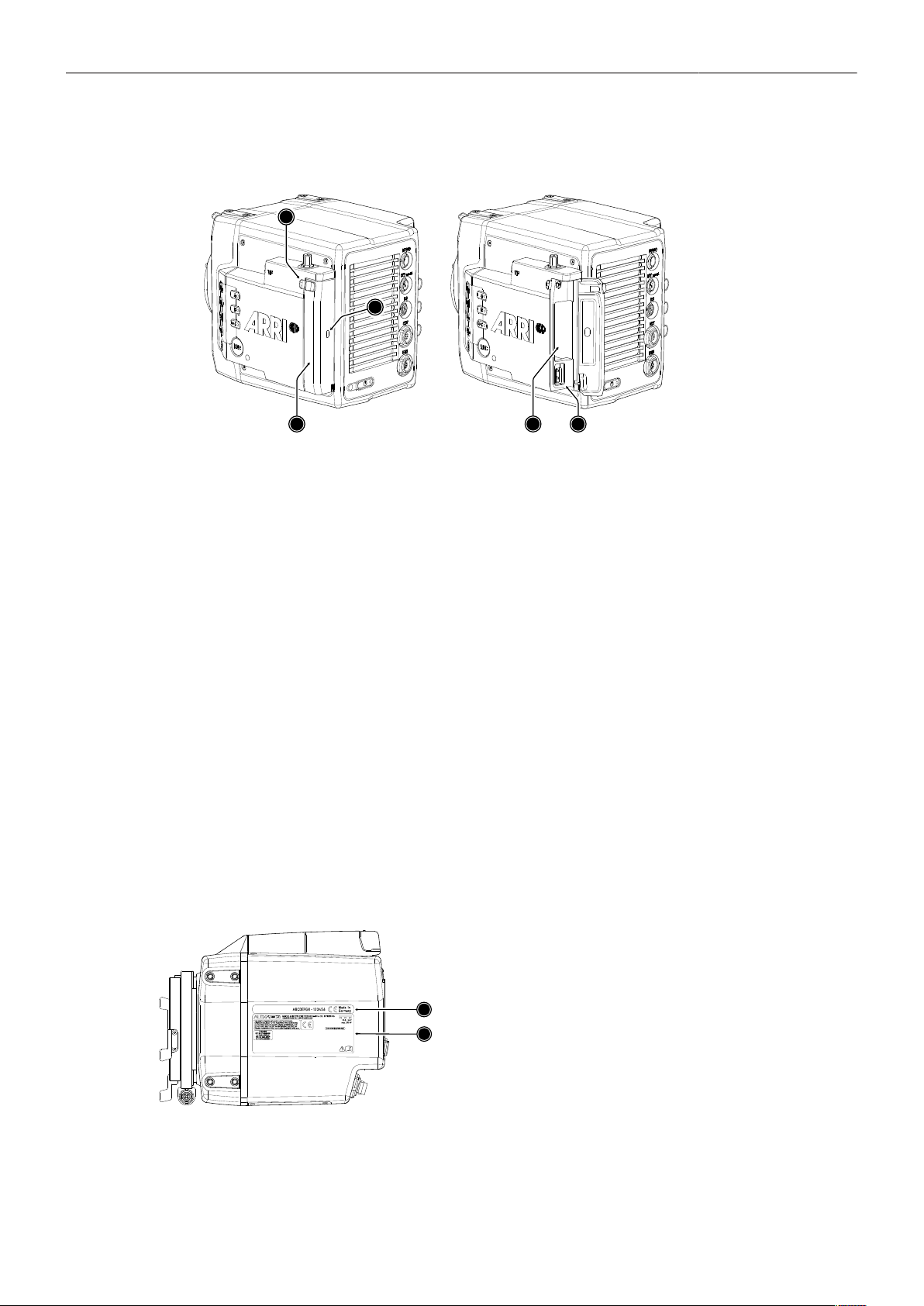
Camera Rear
1
2
3
4
5
6
7
8
9
1
Boot Status LED
2
POWER Button
3
Camera Status LED
4
Media Door
5
Media Status LED Window
6
WiFi Antenna Connector
7
Fan Outlet
8
White Radio Antenna Connector
9
Rear Connectors
Camera Top
1
2
3
3
1
WiFi Antenna Connector
2
VF Viewfinder Connector
3
Attachment Points for Mechanical Acces-
sories
Camera Bottom
1
2
2
3
4
1
LBUS Connector (on Lens Mount)
2
Attachment Points for Mechanical Acces-
sories
3
Camera ID Label
4
Certification Label
Camera Layout 19
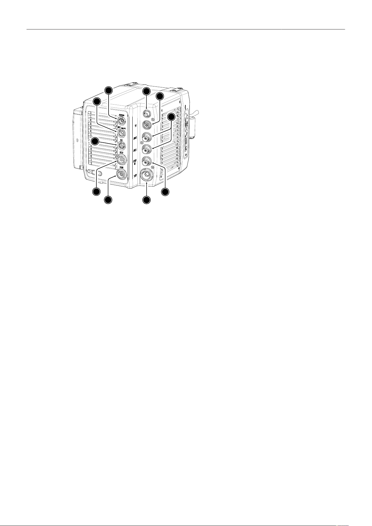
8.1 Camera Rear Connectors
8
7
4
1
6
2
5
3
9
10
1
ETH Connector
2
EXT Connector
3
RS Connector
4
12V Connector
5
AUDIO Connector
6
White Radio Antenna Connector
7
TC Connector
8
SDI Outputs
9
SYNC IN Connector
10
BAT Connector
ETH (10-pin LEMO)
The Ethernet connector is used for camera remote control and service purposes. It supplies regulated
24 V with a current of 0.5 A. Use the ALEXA Ethernet Cable KC 153-S (K2.72021.0) to connect the
camera to a standard RJ-45 Ethernet port.
Note: The ALEXA Remote Control Unit RCU-4 cannot be used with the Ethernet connector of the
ALEXA Mini LF.
EXT (7-pin LEMO)
The EXT connector is a multi-pin accessory connector for camera synchronization and communication
with various accessories, carrying two CAN buses and supplying regulated 24 V accessory power with
a current of 1.0 A. With external adapter EXT-RS (K2.0006170), RS functionality (remote start/stop) is
supported.
RS (3-pin Fischer)
The RS connector outputs regulated 24 V accessory power and can supply external devices with a load
of up to 3.0 A. Besides powering accessories, the RS connector also carries a shutter pulse signal and
can be used to send a remote start/stop signal to the camera.
12V (2-pin LEMO)
The 12 V output with a 2-pin LEMO connector supplies accessories with regulated 12 V with a current
of 1.0 A.
AUDIO (6-pin LEMO)
The audio connector is a 2-channel +24 dBu line level audio input with an additional regulated 12 V
power output with a current of 0.5 A. Use the ALEXA Mini LF Audio connector with cable (K2.0023988)
to connect audio sources.
White Radio Antenna Connector (Female RP-SMA)
White radio allows for wireless lens control, lens data communication and remote control of basic
camera functions using the wireless hand units of the ARRI Electronic Control System.

Camera Layout 20
Note: Do not leave the antenna connector open during operation or transport. The radio module
inside could be damaged by electrostatic discharge on the open connector. Use the originally supplied
antenna only.
TC (5-pin LEMO)
The TC connector is a 5-pin LEMO socket. It accepts and distributes LTC (Longitudinal Timecode)
signals. It can be used to
jam-sync the camera timecode to a timecode generator or another camera
transmit the camera timecode to a timecode generator or another camera
SDI 1&2 (BNC)
Besides the viewfinder output, SDI 1&2 are the main monitoring outputs of the camera. The camera
menu offers various settings to configure the outputs such as surround view, status information or frame
lines. Both SDI BNC connectors output SDI signals in
1920 x 1080 (422 1.5G, 422 3G, 444 3G)
3840 x 2160 (422 6G)
according to SMPTE standards 292M, ST 424:2012 and ST 2081.
SYNC IN (BNC)
A BNC socket for reference signal input, the SYNC IN connector accepts analog Black Burst signals
and Tri-Level HD signals.
BAT (8-pin LEMO)
The BAT connector is the main power input of the ALEXA Mini LF and accepts an input voltage range
from 11.0 to 34.0 V DC. You can use power cables KC50-S (K2.75007.0) or KC50-SP-S (K2.0001275)
or one of the various on-board adapter plates for V-Mount and Gold Mount batteries to supply the
camera with power.
NOTICE
Connecting or disconnecting devices or cables while recording can disturb the image/audio signal
due to static electricity.
For information about connector pin outs please see "Connector Pin-Outs", page 124.
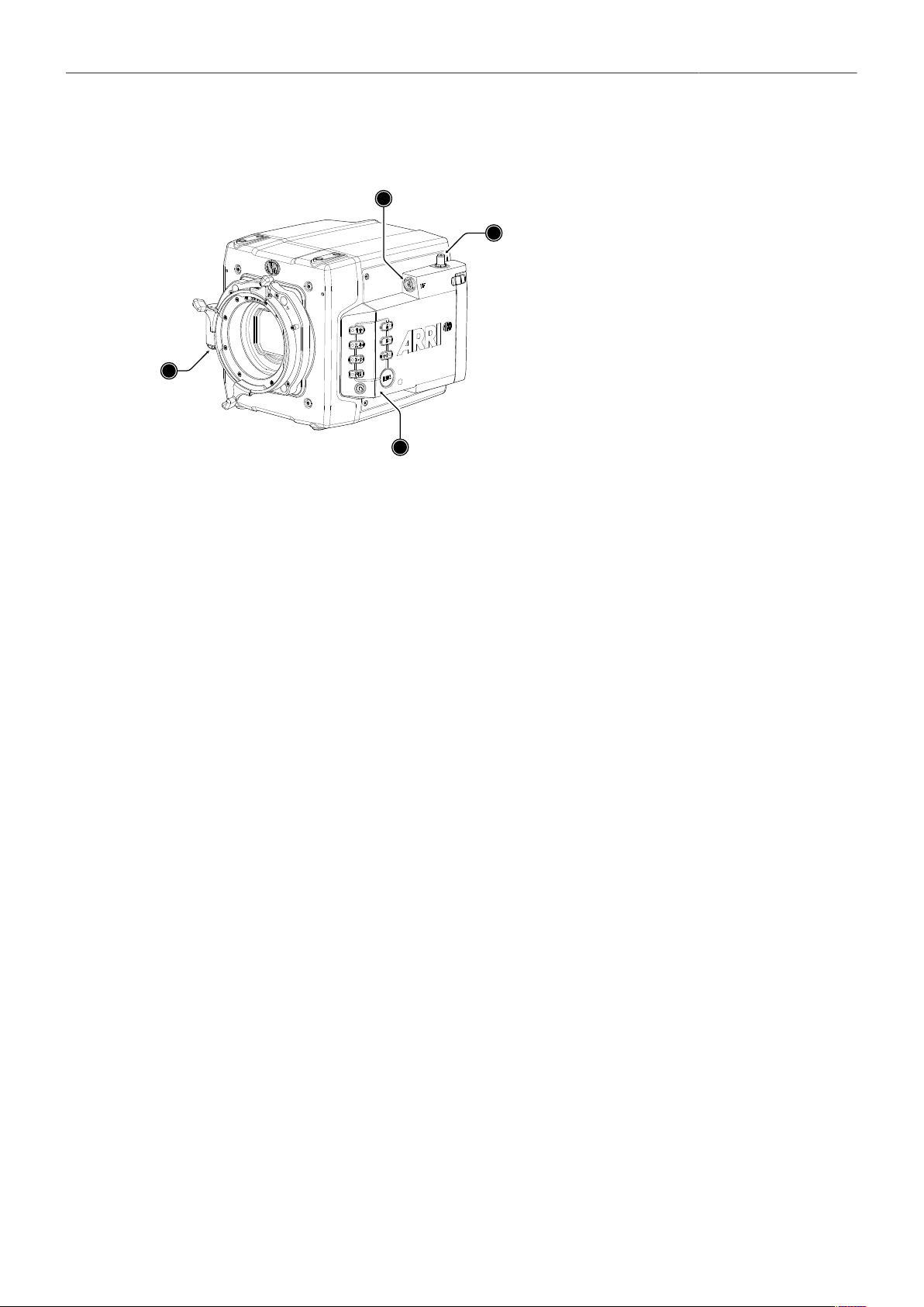
Camera Layout 21
8.2 Camera Left and Front Connectors
2
3
1
4
1
LBUS Connector (on Lens Mount)
2
VF Viewfinder Connector
3
WiFi Antenna Connector
4
Camera Buttons
LBUS Connector (4-pin LEMO, on LPL Lens Mount)
The LBUS connector is used to connect daisy-chainable LBUS devices of the ECS Electronic Control
System (lens motors, ARRI Master Grips, ARRI OCU-1 and ARRI LCUBE CUB-1) to the camera and
supplies regulated 24 V with a current of 2.0 A max.
VF Viewfinder Connector (CoaXPress)
The ALEXA Mini LF uses an industrial CoaXPress interface to connect the MVF-2 viewfinder with the
camera. The interface transmits power, video and control data and supports cable lengths of up to 10 m
(33 ft). The VF connector comes without a key, so the VF cables plug in regardless of their orientation
and support hot plugging of the viewfinder.
WiFi Antenna Connector (RP-SMA)
Besides the built-in WiFi antenna behind the camera label on the right side, the ALEXA MINI LF is
equipped with a second WiFi antenna connector above the media bay on the camera left side. Both
internal and external WiFi antenna work together, and if needed, the external antenna output can be
disabled in the camera menu.
Note: Do not leave the antenna connector open during operation or transport. The radio module
inside could be damaged by electrostatic discharge on the open connector. Use the originally supplied
antenna only.
Camera Buttons
Besides the REC and LOCK button, the camera is equipped with six freely assignable user buttons plus
a FN function button for quick access to frequently used functions. All buttons (except for the LOCK
button) have an adjustable background illumination. For further information please see "User Buttons",
page 107 and "Function Button FN", page 46.
Camera Layout 22
8.3 Media Bay
2
1
3
4
5
1 Media Bay Door
2 Media Bay Door Release
3 Recording Media LED Window
4 Recording Media Slot
5 USB Connector
Recording Media Slot
The ALEXA Mini LF records clips onto Codex Compact Drives, using the media bay on the camera left
side. A small window (3) in the media bay door shows the LED of the Compact Drive. To access the
media slot, slide the media bay door release (2) towards the camera back so that the spring-loaded
door jumps open. For more information please see "Recording Media Handling", page 63.
USB Connector
The camera saves data such as user setups, frame grabs and system logs to USB 2.0 memory sticks
with FAT file system. Software updates, additional frame lines and ARRI look files are loaded onto the
camera from the USB memory stick. The USB connector can also be used to charge USB devices and
supplies 5.0 V with a maximum current of 0.5 A.
For more information please see "Working with Lists and Import of Files", page 44 and "User
Storage Handling", page 47.
8.4 Product Identification
1
2
The camera serial number (1) and the FCC/CE confor-
mity label (2) are located on the bottom of the camera.
The serial number consists of the last 5 digits of the
product number K1.0024074-XXXXX.

Camera Support 23
9 Camera Support
This chapter provides information on how to attach commonly used accessories to the camera.
ARRI offers a wide range of mechanical accessories, please see our Configuration Overviews for more
information.
Mechanical accessories are attached to the M4 mounting points located on the front top and bottom of
the camera. This chapter describes how to mount the most important mechanical accessories:
Mini Adapter Plate MAP-2A
(K2.0023839)
The MAP-2A is a base plate for 15 mm lightweight support and
features an improved rod clamping mechanism as well as multi-
ple 1/4-20 and 3/8-16 mounting points. It fits to the top and bot-
tom of the ALEXA Mini / Mini LF.
Bridge Plate Adapter BPA-4
(K2.0006352)
This spacer allows standard bridge plates to be mounted to the
Mini Adapter Plate MAP-2 / MAP-2A. The BPA-4 also features
centered 3/8 inch and 1/4 inch threads for standard tripod plates.
Fits ALEXA Mini / Mini LF.
Bridge Plate BP-8
(K2.0031436)
The BP-8 helps to optimize camera rig balance when combined
with the range of ARRI bottom plates. It brings compatibility with
studio 19 mm rod systems to an increasing number of ARRI and
third party cameras.
Mini Side Brackets
MSB-2 and MSB-3
(K2.0014957, K2.0023546)
The Mini Side Bracket MSB-2 offers support for lens motor in
configurations that require lightweight base plates with no rod
support, such as lightweight stabilizer systems or drones. Suits
ALEXA Mini, and also ALEXA Mini LF on camera right.
The MSB-3 is a side bracket designed around the media bay
of the ALEXA Mini LF and the new viewfinder connector on the
camera left.
Center Camera Handle CCH-2
(K2.73002.0)
The Center Camera Handle CCH-2 offers numerous mounting
points in the industry standard 3/8-16 and 1/4-20 inch thread
sizes.
Mini Viewfinder Bracket MVB-1
(K2.0006140)
The MVB-1 allows the MVF-1 and MVF-2 viewfinders to attach to
ALEXA Mini / Mini LF via 15 mm LWS rods and viewfinder mount.
Requires the Mini Adapter Plate MAP-2A or other 15 mm rod
support.
Required Tools
3.0 mm Allen key
8-10 mm (5/16") flathead long shaft screwdriver
To avoid damage while assembling and retrofitting, always place the camera on a padded, firm, flat and
level surface.
Camera Support 24
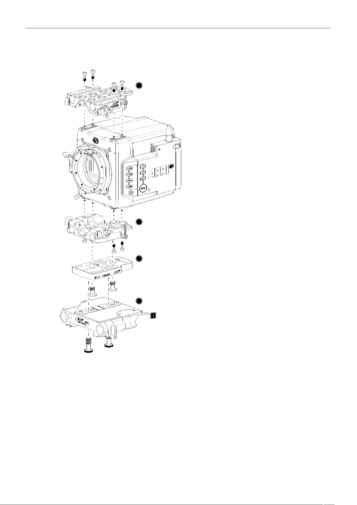
Mounting MAP-2A, BPA-4 and BP-8
► Using a 3.0 mm Allen key, fasten the Mini
Adapter Plate MAP-2 or MAP-2A (1) to the
camera top attachment points with the four
3.0 mm hex screws. Tighten them cross-
wise.
► Fasten another MAP-2 (2) to the bottom at-
tachment points.
► Using a flathead screwdriver, fasten the
Bridge Plate Adapter BPA-4 (3) to the bot-
tom of MAP-2 (2) with two screws. Two reg-
ister pins will assure a perfect fitting.
1
2
3
4
► Using a flathead screwdriver, fasten the
Bridge Plate BP-8 (4) to the BPA-4 with two
screws. Two register pins will assure a per-
fect fitting.
Camera Support 25
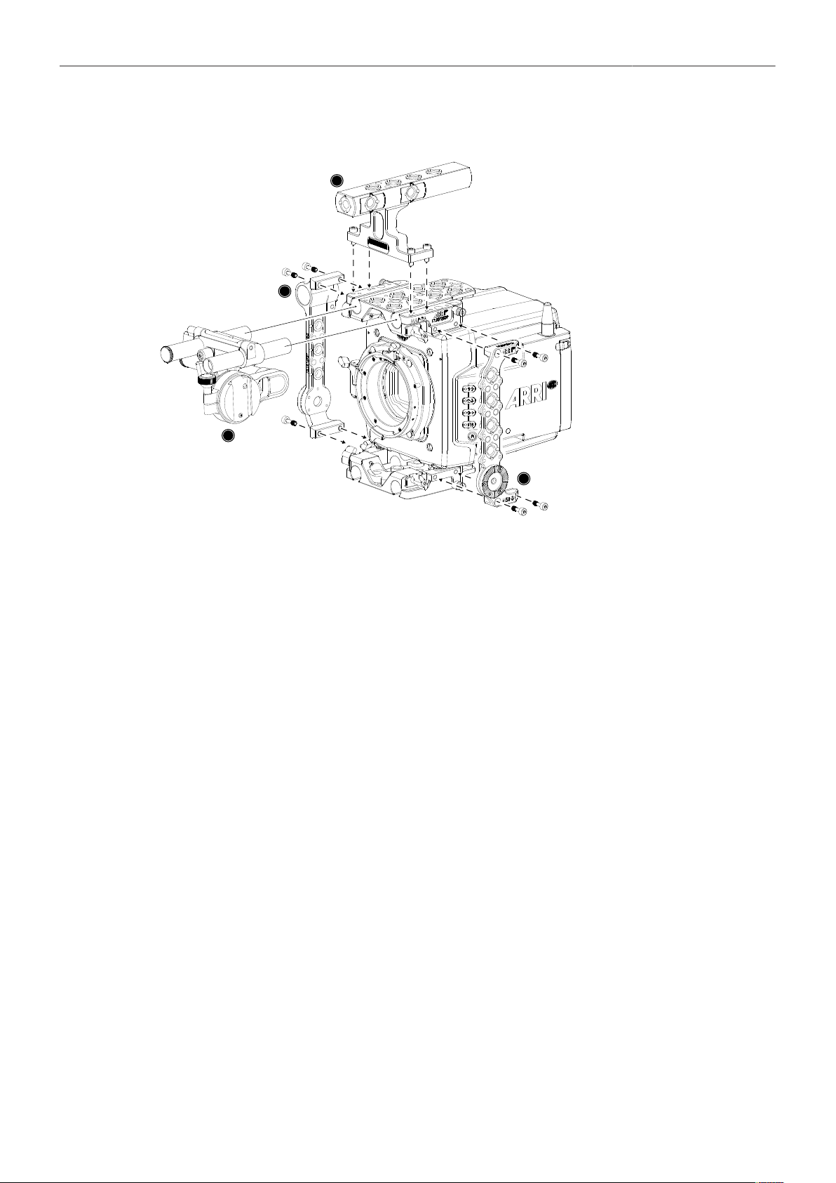
Mounting MSBs, CCH-2 and MVB-1
1
2
3
4
► Using a 3.0 mm Allen key, fasten the Mini Side Bracket MSB-3 (1) to the camera's left side. The
MSB-3 is attached with two 3.0 mm hex screws each to the dedicated mounting points of the top
and the bottom Mini Adapter Plates MAP-2A.
► Identical to the MSB-3 on the camera left side, fasten the MSB-2 (2) with four 3.0 mm hex screws to
the camera's right side.
► Fasten the Center Camera Handle CCH-2 (3) to the top MAP-2A with four 3.0 mm hex screws.
► Open the clamps on the top MAP-2A and attach the MVB-1 (4) 15 mm LWS rods to the top
MAP-2A.
Power Supply 26
10 Power Supply
BAT IN
The ALEXA Mini LF accepts an input voltage range from 11.0 to 34.0 V DC.
The camera can be solely powered through the 8-pin LEMO BAT connec-
tor located at the back of the camera. You can use the KC50-S (K2.75007.0)
or KC50-SP-S (K2.0001275) power cable or one of the various on-board
adapter plates for V-Mount and Gold Mount batteries to supply the camera
with power.
NOTICE
Power solutions from ARRI (K2.0014530, K2.0014531, K2.0014532, K2.0014533) can be used
safely up to a total current of 10 A (e.g. 144 W total at 14.4 V, including camera and powered
accessories). For use cases demanding more than 10 A, alternative solutions such as block
batteries or the B-Mount Power Splitting Box should be considered.
Accessory Power
24 V
The total available power on the 24V ACC converter is just below 100 W to be compliant with DIN EN
62368 PS2 (limited power source annex Q, table Q.1, single fault tolerant). The camera's 24V ACC
converter power is shared by
RS Connector
EXT Connector
LBUS Connector (on lens mount)
ETH Connector
Typically, the 24V ACC converter delivers a permanent current of 3.0 A at 14.0 V camera supply
voltage and ambient temperatures of 25° Celsius / 77° Fahrenheit.
If the camera supply voltage is low, typically below 14.0 V (the camera is designed for Li-Ion based
batteries that deliver about 14V until discharged to about 10-15%) the boost converter is current limited
and the power on the 24V ACC converter is limited furthermore. Reason here is, that maximum current
draw from the entire camera should not exceed 20A under all conditions since no on-board batteries
can deliver higher currents.
12 V
The 12V ACC converter power is shared by
12V Connector
AUDIO Connector
and outputs 12 V with a max. current of 2 A. If the camera supply voltage is below 13.5 V, the 12 V
ACC converter power output is reduced by approx. 1,5 V.
Power Consumption
In order to process the increased pixel count while still maintaining ALEXA image quality, the ALEXA
Mini LF draws between 69 W and 89 W while recording, with MVF-2 connected, but no further
accessories attached. 69 W have been measured while recording MXF/ARRIRAW in recording
resolution LF 16:9 UHD at 24 fps. 89 W have been measured while recording MXF/Apple ProRes in
recording resolution LF 16:9 2K at 90 fps. Electronic accessories will increase power draw based on the
accessories’ draw.
Power Supply 27
NOTICE
Always keep the BAT connector accessible so that the cable can be unplugged quickly in case of
emergency. Do not use power cables longer than 4m.
Operate the system using only the type of power source indicated in the manual. Unplug the
power cable by gripping the power plug, not the cable.
Do not supply power outside the specified voltage range.
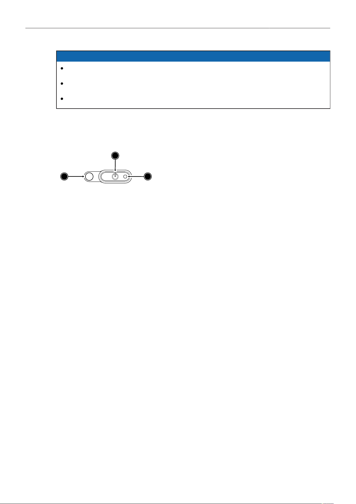
Switching On and Off
The POWER button is located at the lower left on the back of the camera. The power button's
background light is illuminated when the power on the BAT connector is in the valid range.
1
2
3
1
POWER Button with background illumination
2
Boot Status LED
3
Camera Status LED
Switching On the Camera
The background illumination indicates if a supply with sufficient power is connected.
► Press the POWER button (1).
The camera starts booting. While the camera is booting up, the boot status LED (2) is flashing
blue. As soon as the camera has finished the boot process, the boot status LED turns to solid blue.
During the boot process, the ARRI logo is shown in the flip-out monitor of the MVF-2 (if connected).
Switching Off the Camera
► Press and hold the POWER button (1) until the camera has switched off and the boot status LED
(2) turns off.
On the flip-out monitor of the MVF-2 as well as in the viewfinder and the SDI outputs, a countdown
appears while you press and hold the power button. On reaching zero, the camera switches off.
Automatic Boot-up on Power
If the power supply is interrupted with the camera switched on, the camera will automatically repower
and boot-up on reconnection.
Lens Mounts and Lens Handling 28
11 Lens Mounts and Lens Handling
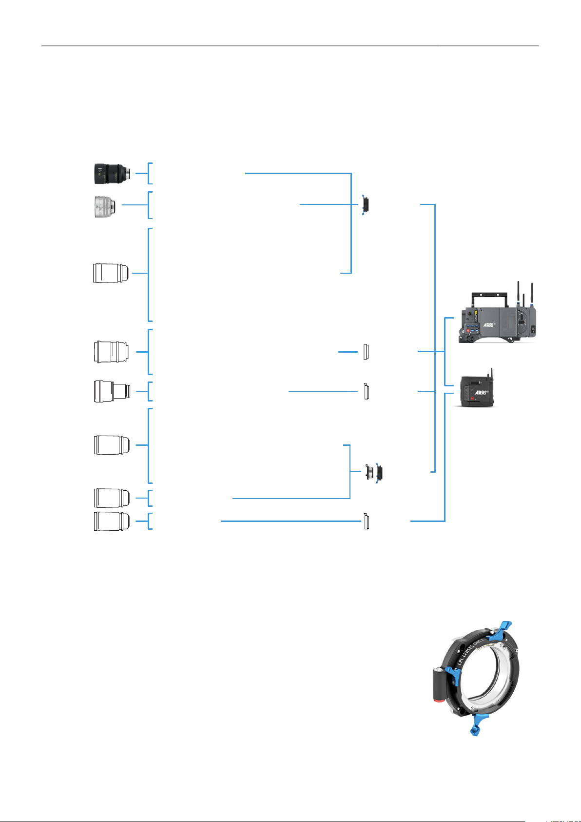
The ALEXA Mini LF is equipped with a universal lens mount base for interchangeable lens mounts
allowing the use of various lenses.
ARRI Rental DNA LF and 65 Format Lenses
DNA LF, Prime DNA, Prime 65 S, Prime 65,
Vintage 765
LPL
Lens Mount
ARRI Large-format Lenses
Signature Prime Lenses
Panavision Large-format Lenses
Primo 70, Primo Artiste, Super Panavision 70,
System 65, PanaSpeed, Primo X, Sphero 65, Vintage 65,
H-Series, Ultra Panatar 1.3x Anamorphic,
Ultra Vista 1.65x Anamorphic
LPL
Lens Mount
& PL-to-LPL
adapter
PL Mount S35 Lenses
Leitz M 0.8 Lenses
PL Mount FF Lenses
Angénieux Optimo Ultra 12x FF/VV, EZ-1 FF, EZ-2 FF;
Cooke S7/i, Anamorphic /i 1.8x; Leitz Thalia;
Sigma Cine Primes; Tokina Cinema Vista Primes;
Zeiss Supreme Primes, Compact Primes, Compact Zooms;
Geckocam G35; P+S Technik Technovision Classic 1.5x,
GL Optics (Leica Macro 100 mm, 60 mm);
Whitepoint Optics TS70; Fujinon Premista Zooms
Vantage Lenses
Hawk 65, Hawk 35 mm, Vantage One T1
XPL52
Lens Mount
Leitz
M-Mount
ALEXA Mini LF
LPL Mount 65 and FF 3
rd
Party Lenses
Leitz Thalia, Angénieux Optimo Ultra 12x FF/VV,
Geckocam G35, P+S Technik, Technovision Classic 1.5x,
GL Optics (Leica Macro 100 mm, 60 mm),
Glaswerk One Vista Vision 2x Front Anamorphic,
Whitepoint Optics TS70
In preparation:
Zeiss (Supreme Primes, Compact Primes, Compact Zooms),
Sigma Cine Primes, Tokina Cinema Vista Primes,
Cooke S7/i, Leitz Primes
PV/PV70
Lens Mount
ALEXA LF
11.1 LPL Mount and PL-to-LPL Adapter
LPL Mount with LBUS Connector
The ALEXA Mini LF LPL (Large Positive Lock) lens mount with
LBUS connector fits ALEXA Mini LF, ALEXA Mini and AMIRA, it sup-
ports LDS-1, LDS-2 and Cooke/i and is compatible to the ARRI ECS
LBUS devices such as the ARRI Master Grips, cforce lens motors
and OCU-1 (Operator Control Unit). In comparison to the PL mount,
The LPL mount has a wider diameter (62 mm vs. 54 mm) and a
shorter flange focal distance (44 mm vs. 52 mm).
Lens Mounts and Lens Handling 29
PL-to-LPL Adapter
The PL-to-LPL adapter offers backwards compatibility with all PL
mount lenses, be they Super 35 or full frame. The adapter attach-
es securely to the LPL lens mount without tools, allowing crews to
rapidly switch between PL and LPL lenses on set. The PL-to-LPL
Adapter can be mounted either so that the LDS contacts are in the
12:00 position for ARRI lenses, or so that the LDS contacts are in
the 3:00 position for Cooke lenses. In both positions the adapter
supports LDS-1 and Cooke /i.
The three most common uses of Super 35 PL lenses on the ALEXA Mini LF are:
1 Using an image expander.
2 Cropping the Super 35 area in post.
3 Using the large illumination circle of Ultra Primes, Master Primes or Ultra Wide Zoom (UWZ).
Some anamorphic lenses have their lens data connectors in the 3:00 position. In this case, use a 1.5
mm hex key to reposition the orientation pin of the PL to LPL adapter so that the lens can be mounted
correctly.
11.2 Changing a Lens
LPL Mount, PL-to-LPL Adapter and PL Mount Lenses
Lens change on the LPL mount, the PL mount as well as the PL-to-LPL Adapter works the same way.
An LDS lens must be mounted with the LDS contacts in the 12:00 position to enable the LDS functions.
Take care not to damage the LDS contacts on the lens and the camera when mounting or unmounting
a lens or lens port cover. Any LDS-2 mount and any LDS-2 lens always have the contacts in the 12:00
position. The description below shows the ALEXA Mini LF with an LPL mount attached. When no lens
is attached to the camera, use the lens port cap to prevent dust from entering the lens cavity.
Removing a Lens or the Lens Mount Cap
1. Turn the bayonet ring (1) anticlockwise
until it stops.
2. Remove the lens port cap.
1
Lens Mounts and Lens Handling 30
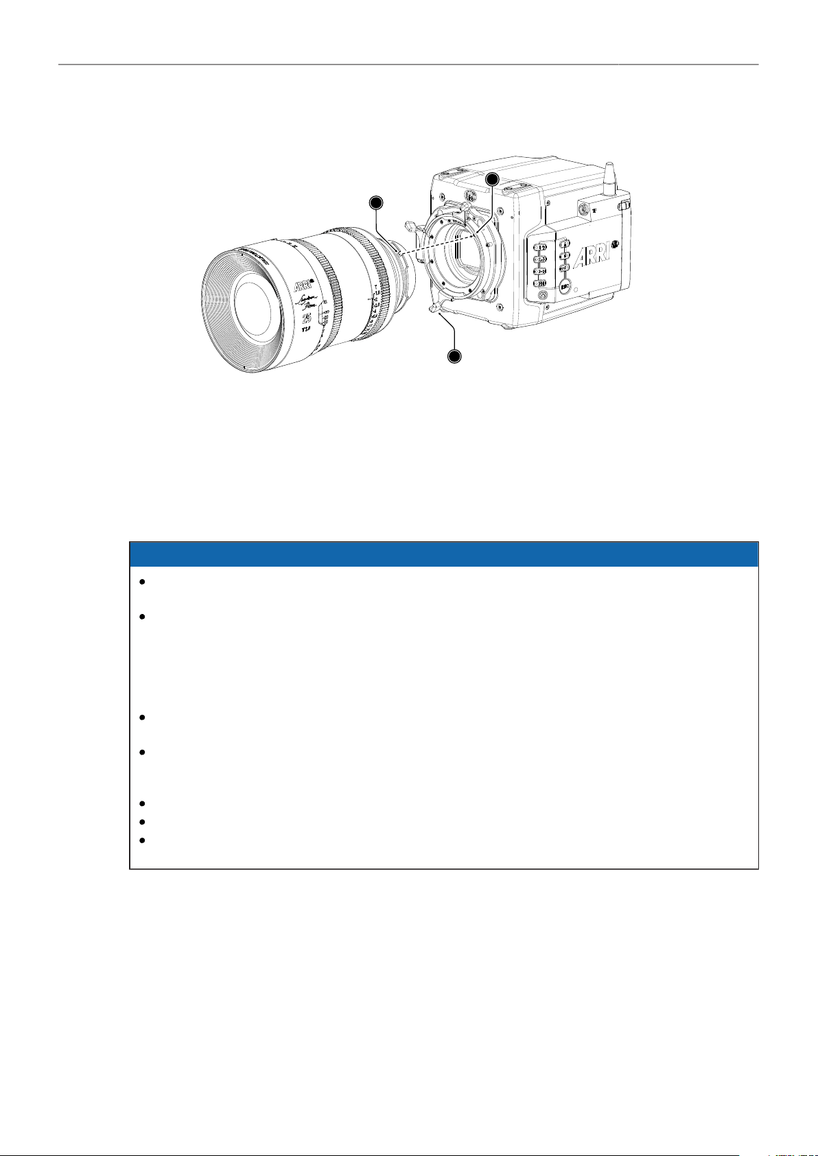
Attaching a Lens
1
2
3
1. Carefully insert the lens into the lens port. Align the notch in the lens flange (1) with the index pin on
the lens mount (2), keeping the lens rotated into a position where the lens markings are visible from
either side of the camera.
2. Press the lens flange flat onto the lens mount.
3. Turn the bayonet ring (3) clockwise until the lens is locked securely.
4. Ensure that the lens is properly mounted.
NOTICE
Changing camera lenses should be done in a dry and dust-free environment. If this is not
possible, take extra care that no dust enters the camera while the lens is off.
When changing lenses, always perform a dust check to make sure no dust has settled on the
sensor cover glass. The sophisticated design principle of the camera’s optical module delivers
outstanding images with a cinematic look and feel, but also makes the imager sensitive to
contamination. Dust particles that have settled on the sensor cover glass during a lens change
may become visible as dark spots in the output image, similar to lint leaving marks on exposed
film. The degree of this effect depends on the aperture of the lens.
When no lens is attached to the camera, immediately place the protective cap on the lens mount
to avoid contamination of the sensor cover glass.
Heavy lenses (above 3 kg / 6.6 lbs) require additional lens support. Using a lens support
guarantees that the weight of the lens will not influence the flange focal depth and reduces stress
on the lens mount.
Do not short-circuit the LDS contacts.
Never exceed the maximum lens mount depth.
Have every lens properly shimmed as prescribed by the manufacturer.
Lens Support
To support a lens use 15 mm or 19 mm studio rods and an appropriate lens bridge. 15 mm rods require
a bridge plate with 15 mm studio rod support, such as a BP-3 / BP-9 + MAP-2, while 19 mm studio
rods require a bridge plate with 19 mm studio rod support, such as a BP-12 or BP-5 / BP-8 + BPA-4.
Mount the Lens Support LS-10 for 15 mm rods by pushing it onto the rods from the front. Mount the
Lens Support LS-9 for 19 mm studio rods by clipping it on the rods from the top. Slide the bridge into
position on the rods directly under the lens support ring on the lens, and fix it in place by tightening the
lever on its side. Align and tighten the center screw in the lens support ring, adjusting the height of the
center screw with the lever on the back of the lens bridge.
Lens Mounts and Lens Handling 31
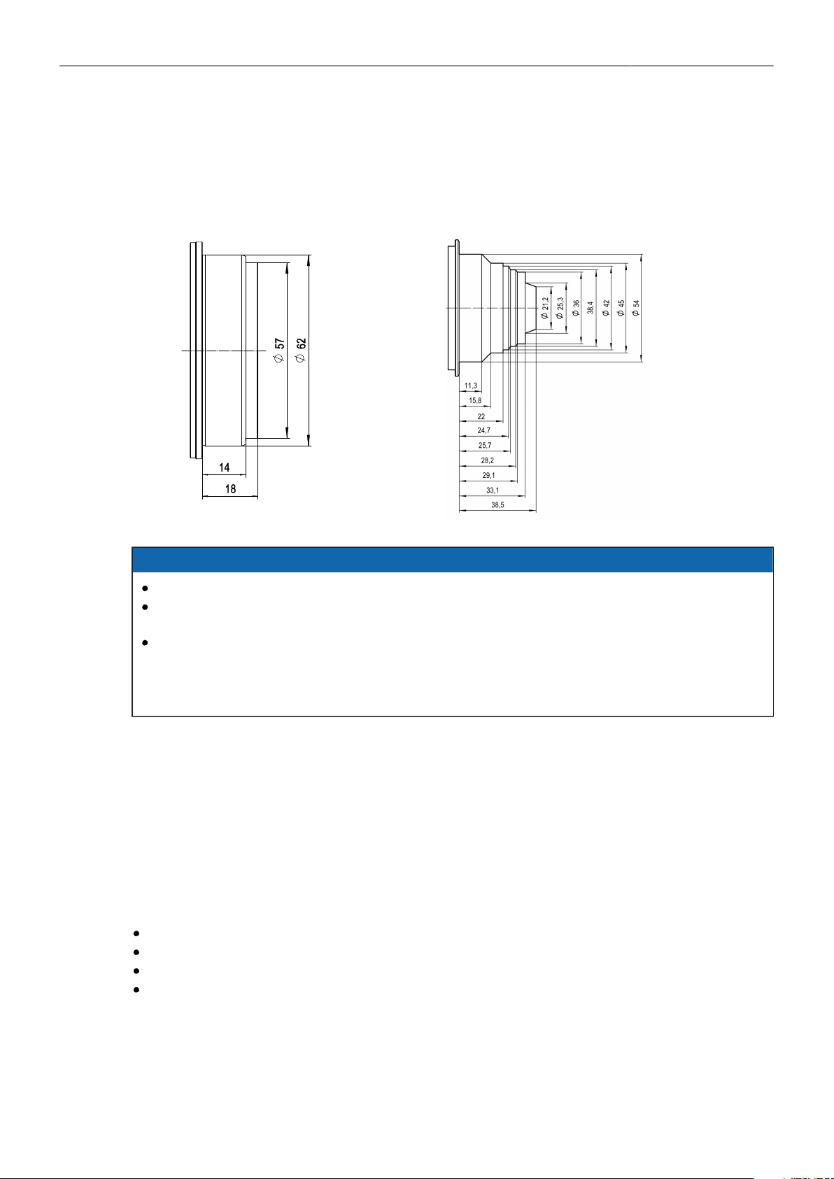
11.3 Maximum Lens Mounting Depth
To avoid damage or injury when using LPL mount lenses or PL mount lenses (with PL adapter on LPL
mount), use only lenses that do not exceed the following dimensions:
LPL mount lenses: PL mount lenses:
NOTICE
Risk of damage and injury from improper lenses!
To ensure maximum allowable lens mounting depth, and to avoid damage or injury, always have
your camera shimmed correctly.
LPL mount lenses with more than 18.00 mm mounting depth and PL mount lenses with more
than 38.50 mm mounting depth might damage internal filters and the camera. Shards from
broken filter glass might cause injury. Always check the lens mounting depth before mounting or
changing a lens.
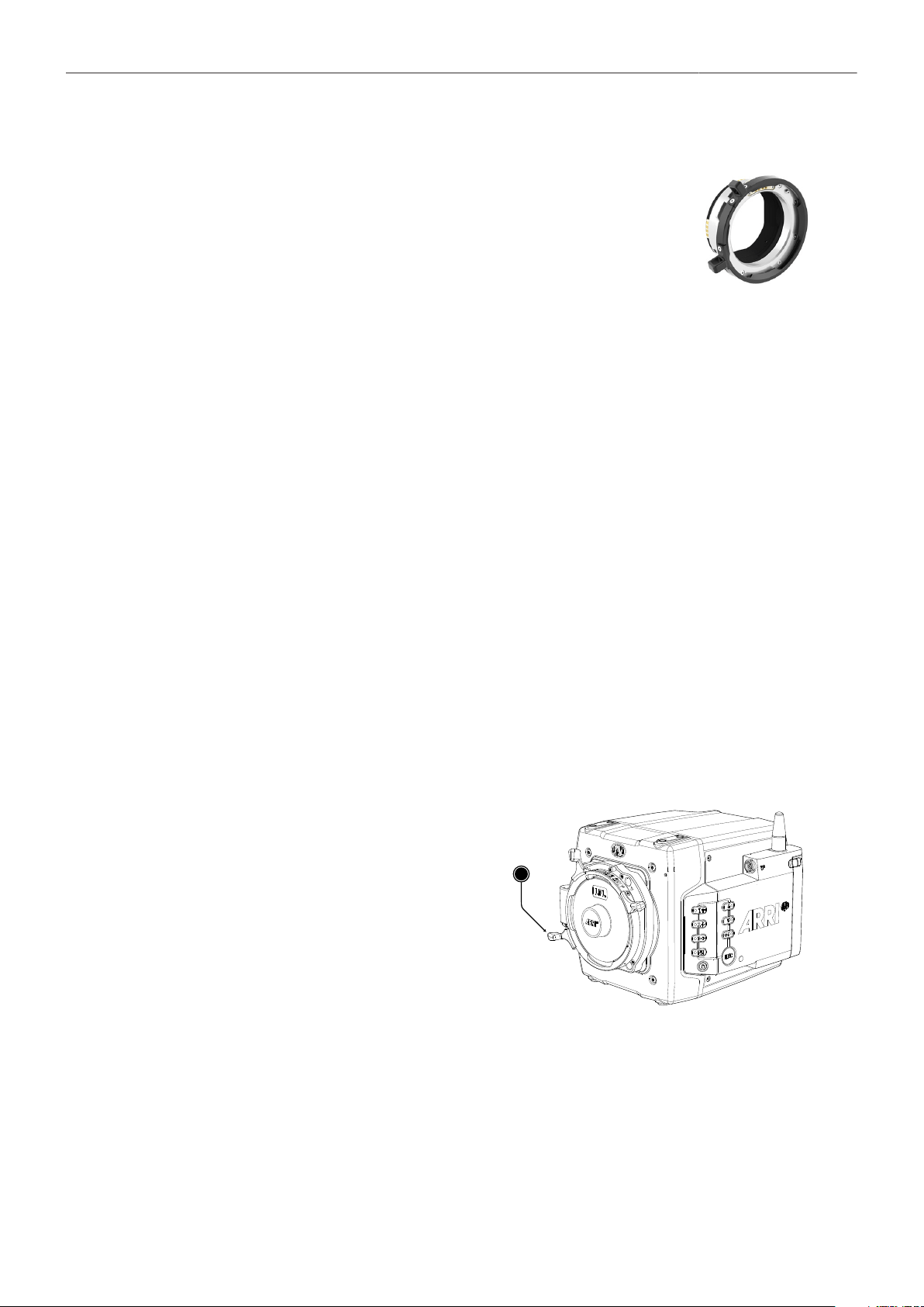
11.4 Changing the Lens Mount
The ALEXA Mini LF is equipped with a universal lens mount base that uses the same camera to lens
mount interface as used on the ALEXA Mini and AMIRA, so all lens mounts that fit on ALEXA Mini and
AMIRA will physically also fit on the ALEXA Mini LF. However, since most of those lens mounts have
been designed for a Super 35 sensor, they will show vignetting in larger format.
Required Tools and Precautions
3.0 mm Allen key
Camera switched off and power source disconnected
Lens removed and properly stored
Make sure to protect all optical surfaces when changing a lens mount
Lens Mounts and Lens Handling 32
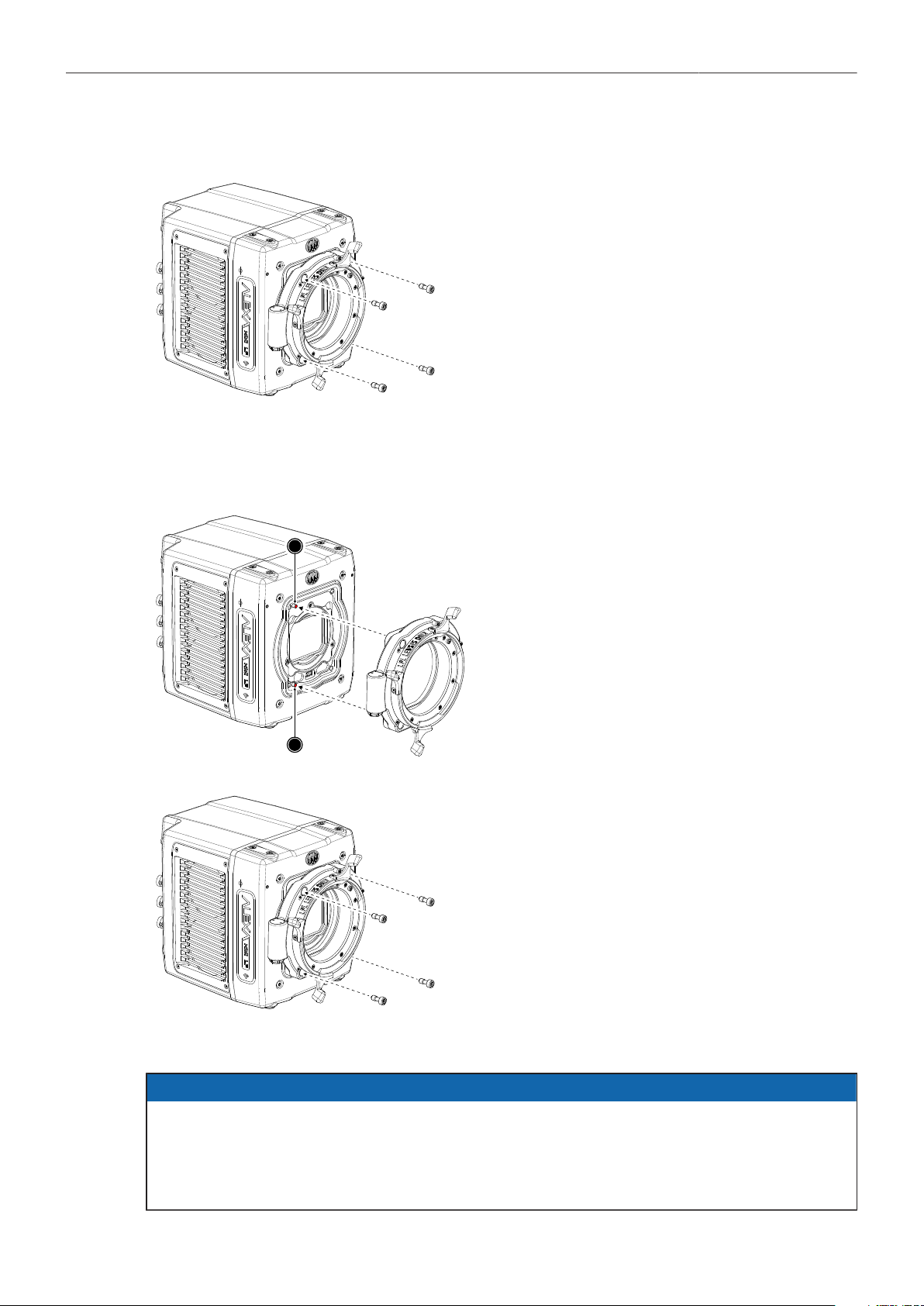
Removing a Lens Mount (here: LPL Mount)
1. Switch off the camera.
2. Crosswise, loosen all four lens mount screws
with a 3.0 mm Allen key.
3. Carefully remove the lens mount.
4. Store the lens mount in a case for dust pro-
tection and install a different lens mount.
Installing a Lens Mount (here: LPL Mount)
1
1
1. Switch off the camera.
2. Properly align the lens mount with the two
guiding pins (1) on the camera's universal
lens mount base.
3. Crosswise, hand-tighten all four lens mount
screws with a 3.0 mm Allen key.
NOTICE
After each lens mount change, always check the flange focal depth of the camera.
Have the flange focal depth always corrected by properly skilled personnel.
Flange focal depth correction requires special tools and training that meet ARRI guidelines.
For all flange focal depth issues, contact a qualified ARRI Service Center.
Lens Mounts and Lens Handling 33
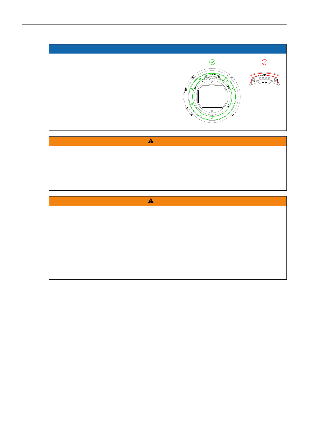
NOTICE
When adjusting the flange focal depth on the
LPL mount make sure to insert the shims in
the correct orientation. Inserting the shims in
the incorrect orientation (flipped) may result in
a short circuit on the LDS print, compromising
LDS functionality (lens detection and lens data).
WARNING!
Condensation! Risk of electric shock and damage!
Humidity may ingress due to misinstalled lens mounts!
When installing a lens mount, always align and attach properly; never apply force.
Hand-tighten all screws crosswise before final tightening.
Always tighten crosswise with the prescribed tool.
WARNING!
High voltage! Risk of electric shock and fire!
Short circuits may entail lethal injury and damage!
Before each lens mount change, always switch off the camera and disconnect all power sources.
Changing the lens mount while the camera is powered may permanently damage the camera and
lens mount.
Protect sensor and electrical system: Always store the camera with a lens mount properly installed
and capped.
Immediately replace each lens mount after removal.
Change lens mounts in a dust-free environment only.
11.5 Lens Data
ARRI Lens Data System (LDS)
ARRI's Lens Data System (LDS) comprises a range of products generating highly accurate lens
metadata for use on set and in post. LDS describes digital lens settings. Lenses with LDS functionality
deliver information about its current settings (focus distance, iris, focal length) to the camera; the
camera interprets these values and transmits the information to its recording module and optionally to
any further accessories connected to the camera such as a Wireless Compact Unit WCU-4 or ARRI
Master Grips. Lens data is displayed in the viewfinder and as overlays on the SDI outputs, and all lens
data will be embedded in the recorded files as well as the SDI stream.
LDS-2 is the next evolution of ARRI’s Lens Data System for ARRI's Electronic Control System and a
new generation of lenses. LDS-2 delivers more accurate and faster lens data. Compared to LDS-1
it eliminates the need for initial calibration through absolute encoders which cuts time on set when
changing lenses. The new system uses a 8.7x faster interface that enables lens manufacturers to send
more data to the camera than before. LDS-2 extends the possibilities of lens data and is being licensed
to other lens and camera manufacturers.
For more information about the Lens Data System, please visit our Lens Data System FAQs web page.
Lens Mounts and Lens Handling 34
ARRI Lens Data Archive (LDA)
Lenses without LDS can be integrated into the system via the Lens Data Archive (LDA). By mapping
a lens, all information about the lens, its scales, name, and serial number can be transferred into a
lens archive. When using the lens the next time all that has to be done is to load the lens file for that
lens from the Lens Data Archive and calibrate the motors. It takes about 5 minutes to map a lens: after
attaching the lens and connecting and calibrating motors (or Lens Data Encoders) on each axis of
the lens, the mapping can be done with the Wireless Compact Unit (WCU-4). These lens files can be
loaded to the camera.
Cooke /i
The LPL mount also offers basic Cooke /i support for direct lens metadata capture through the LDS
contacts. The cameras can store a subset of /i lens data (focus distance and iris settings) as dynamic
camera metadata. The basic /i compatibility has been tested and approved by Cooke Optics Limited.
For support and questions about /i Technology, please contact Cooke Optics directly.
The camera supports the Cooke /i protocol for lenses running firmware versions according to the
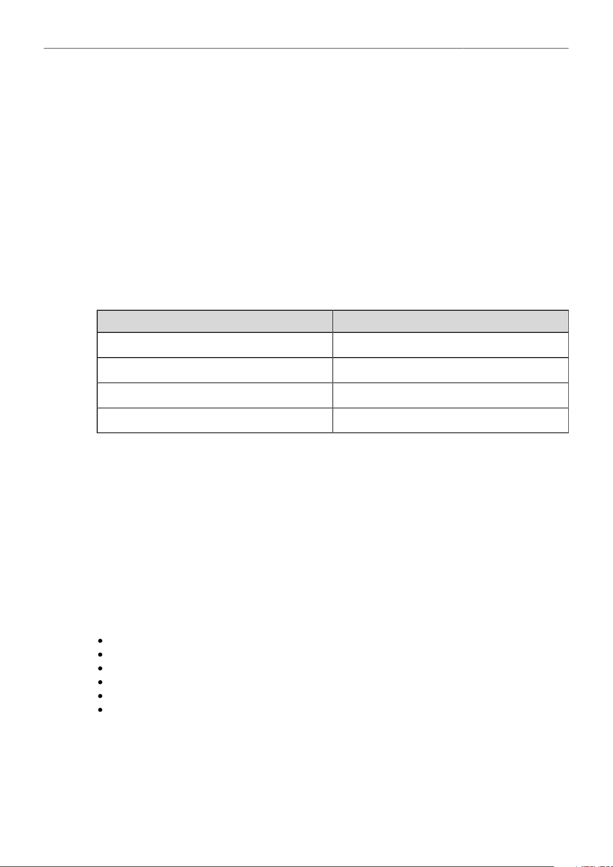
following table.
Lens type FW version
S4 /i Prime lens (10-bit) 0.29 or higher
S4 /i Prime lens (12 bit) 0.39 or higher
S4 /i Zoom lens (10 bit) 1.29 or higher
S4 /i Zoom lens (12 bit) 1.39 or higher
The firmware version can be retrieved from the lens with the Cooke Viewer Lens Display program. For
detailed information, please contact Cooke Optics directly.
Lens Data Display in Camera
Lens data can be displayed as camera status overlays in the viewfinder and the SDI outputs. Single
overlays for focus distance, iris and focal length are displayed. The camera can be set to display
either metric or imperial readings for the focus distance overlay. For further information please see
page 76.
Lens Data in Metadata
Lens data is dynamically written to the metadata of MXF/Apple ProRes and MXF/ARRIRAW files and is
output in the SDI stream.
Metadata values include
Lens Model
Lens Serial Number
Lens Distance Unit
Lens Focus Distance
Lens Focal Length
Lens Iris
Multi Viewfinder MVF-2 35
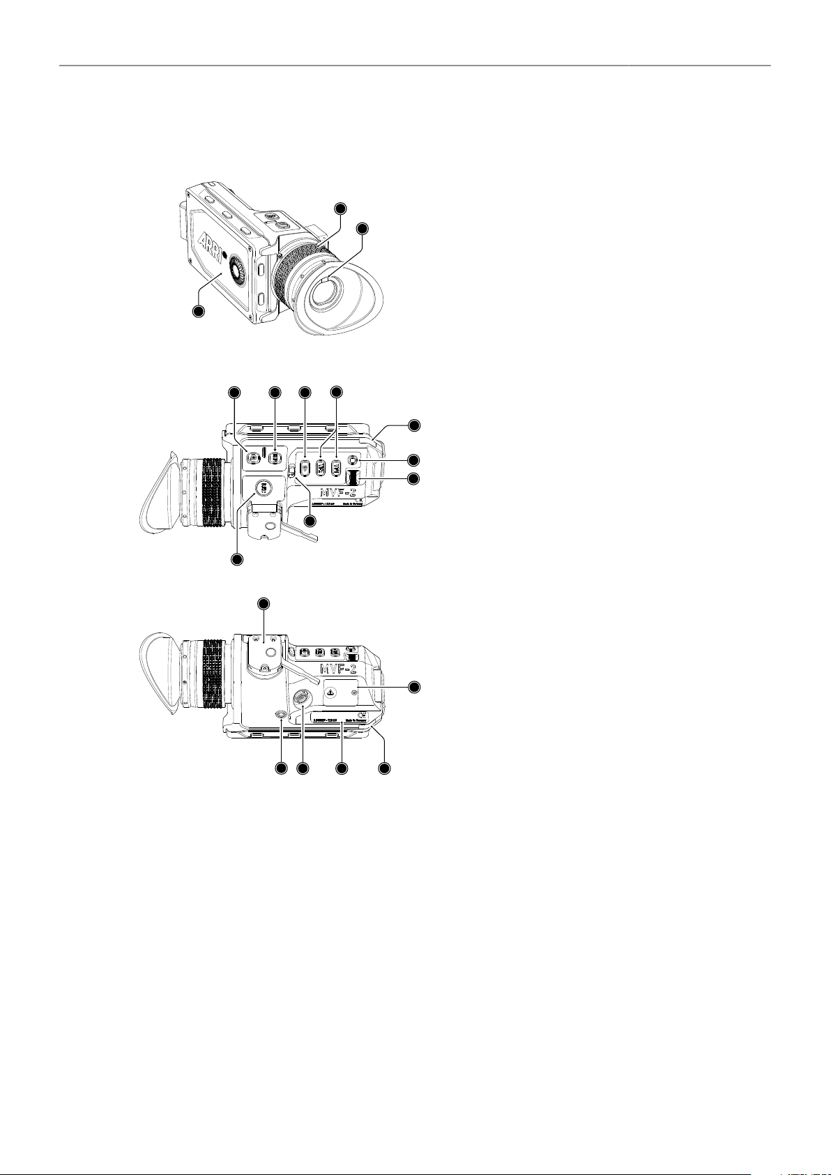
12 Multi Viewfinder MVF-2
1
3
1
2
1
1
Flip-out Monitor
2
Diopter Adjustment
3
Proximity Sensor
12
4
5
6
7
8
9
10
11
4
ZOOM Button
5
EXP Button
6
PLAY Button
7
VF 1&2 User Buttons
8
Top Tally Light
9
SET Button
10
User Wheel
11
LOCK Switch
12
REC Button
13
14
15
16
17
18
13
Dove Tail
14
Service Cover
15
Bottom Tally Light
16
Product Label
17
Viewfinder Connector
18
Headphones Out
OLED Display
The MVF-2 is equipped with a high contrast, temperature controlled 1920 x 1080 OLED display.
Flip-out Monitor
The 4" flip-out monitor (1) with up-and-down tilt function can display the camera live image or the main
user interface, providing full access to camera functions and menus. See the next chapter for more
information.
Diopter Adjustment
With the camera switched on and looking into the viewfinder, twist the ring (2) left or right to adapt the
viewfinder image to your visual acuity. With the help of the scale labelled from 1 to 9 you can easily
remember your adjustment when different people are using the viewfinder. The diopter adjustment can
compensate from -5 to +5 diopters.

Multi Viewfinder MVF-2 36
Proximity Sensor
This infrared sensor (3) automatically deactivates the MVF-2's internal OLED panel when you withdraw
your eye to prevent burn-ins on the panel and activates it again as soon as you approach the eyepiece.
Do not permanently cover the sensor as this might cause irreversible burn-in on the OLED panel.
Built-in Eyepiece Heater
The MVF-2 is equipped with a built-in eyepiece heater to prevent fogging of the eyepiece when
shooting in cold environments. The eyepiece heater can be activated in the camera menu and only
becomes active when the eyepiece has a temperature of 15 °C (59 °F) or below. In extremely cold
environments please use the Heated Eyecup HE-7.
EXP (Exposure Tool Button)
The EXP button (4) activates and deactivates the exposure tool (either false color or zebra) for the
viewfinder and the flip-out monitor.
ZOOM Button
Pressing the ZOOM button (5) activates the viewfinder zoom feature for a temporary 2.25x zoom-in to
quickly check focus. The magnification ratio is 1:1, or one sensor pixel to one viewfinder display pixel.
PLAY Button
Press and hold the PLAY button (6) for two seconds to start in-camera playback from the recording
media.
VF1 and VF2 User Buttons
The MVF-2 has two user buttons, VF1 and VF2 (7). You can assign a frequently used function to each
button.
User Wheel and SET Button
The user wheel and the SET button (9, 10) provide the same functionality as the JOGWHEEL on the
flip-out monitor (see next chapter) and can be used for menu navigation and adjustment when the flip-
out monitor is used with the display visible in the folded-in position.
LOCK Switch
The LOCK switch (11) locks all MVF-2 buttons. A dedicated lock icon is displayed on the HOME screen
as well as in the viewfinder.
REC Button
The REC button (12) starts and stops recording to the recording media. With no recording media
inserted, the button is inactive.
Product Label
The product label (1) shows the MVF-2 serial number. The serial number consists of the last 5 digits of
the product number K1.0024074 - XXXXX.
Viewfinder Connector
The ALEXA Mini LF uses an industrial CoaXPress interface to connect the MVF-2 viewfinder with the
camera. The interface transmits power, video and control data and supports cable lengths of up to 10 m
(33 ft). The VF connector comes without a key, so the VF cables plug in regardless of their orientation
and support hot plugging of the viewfinder.
Multi Viewfinder MVF-2 37
Headphones Out
The headphones out (18) is a 3.5 mm TRS connector (headphone jack), which outputs all four audio
channels with a maximum power of 2.5 dBm.
NOTICE
Constantly covering the proximity sensor of the MVF-2 can cause an irreversible burn-in on the
viewfinder OLED display. If you need to cover the viewfinder, please disable the EVF OLED first
using the EVF power setting: MENU > Monitoring > EVF/MONITOR > Settings > EVF Power
The Heated Eyecup HE-6 is not compatible with the MVF-2 viewfinder. When using the Heated
Eyecup HE-6, the proximity sensor that activates the OLED display will always be covered. In
this state, the OLED display will not switch off when not in use, this can cause an irreversible
burn-in on the OLED display. Please use the Heated Eyecup HE-7 instead. This is compatible
with the MVF-2 viewfinder.
When shooting in hot environments make sure to have the viewfinder mounted on the viewfinder
bracket to ensure proper cooling.
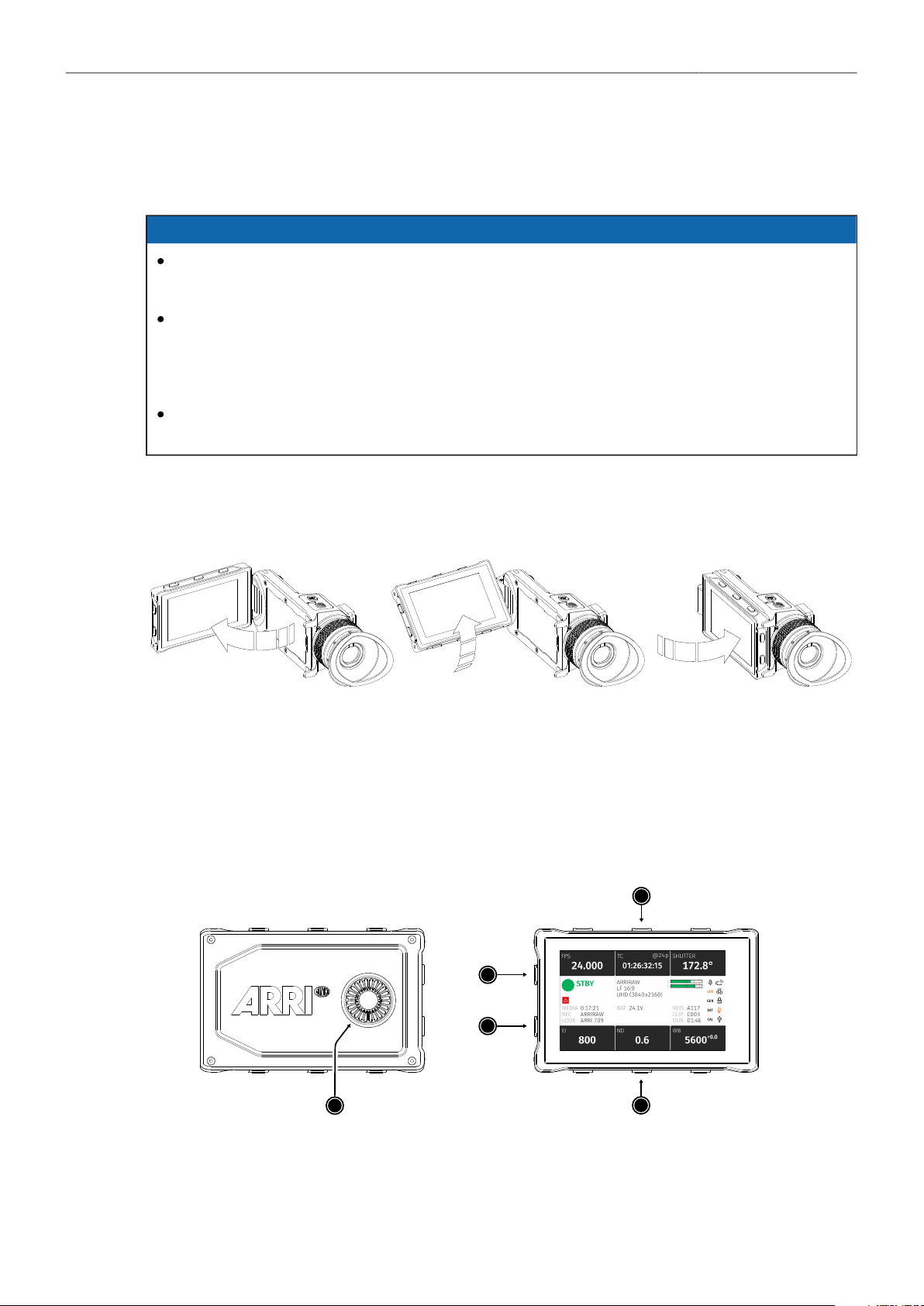
12.1 Flip-out Monitor
Adjusting the Flip-out Monitor
Fold out, swivel and fold in the monitor to put the display visible in the folded-in position. The image on
the monitor automatically adjusts its orientation, or can be set to the desired orientation in the camera
menu).
Flip-out Monitor
The 4" flip-out monitor with up-and-down tilt function can display the camera live image or the main
user interface (HOME screen and camera menu).
2
3
4
5
1
1 JOGWHEEL 2 HOME / LIVE Button
3 MENU / BACK Button
4 Upper Screen Buttons
5 Lower Screen Buttons

Multi Viewfinder MVF-2 38
JOGWHEEL
The JOGWHEEL (1) is used to
► scroll or navigate through lists and menus
► change values (by scrolling up or down)
► access and confirm settings (by pressing the JOGWHEEL center)
HOME / LIVE Button
The HOME / LIVE button (2) toggles to display either the HOME screen (shown in the image above) or
the camera live view.
MENU / BACK Button
Pressing the MENU / BACK button (3) while on the HOME screen or in camera live view opens the
camera menu. While in the camera menu, it serves as a BACK button.
Screen Buttons
The MVF-2 flip-out monitor has six screen buttons, three above (4) and three below (5) the screen.
Their function depends on the screen content and is labeled directly below or above each button.
Unlabeled buttons do not have a function for that screen. A grayed-out label indicates that the function
is currently not available.
12.2 MVF-2 Cables
The Multi Viewfinder MVF-2 is connected to the camera using an industrial CoaXPress cable. The
cable center pin and shield transport power, video, audio and data and the interface allows for hot-
plugging the viewfinder. Since the VF connector has no key, the viewfinder cable can be plugged in in
any orientation.
NOTICE
When attaching a new viewfinder to the camera for the first time, it may take around 2 minutes until
the viewfinder OLED calibration is fully loaded and activated.
Viewfinder Cables
MVF-2 viewfinder cables are available in the following lengths:
ID No.
K2.0023915
K2.0023943
K2.0023944
K2.0023945
Length
0.35 m (1.15 ft)
0.5 m (1.5 ft)
2.0 m (6.5 ft)
10.0 m (33 ft)
Suggested Use
For use of MVF-2 on camera left side in handheld mode
For use of MVF-2 with VEB-1 or VEB-3, for use on camera right side
The medium length for remote use
The longest possible length for remote use
Menu Operation 39
13 Menu Operation
The camera menu has a tree structure and the name of the current submenu is displayed across the
top of every screen. To access the menu, press the MENU / BACK button on the MVF-2 or connect to
the camera via WiFi or Ethernet and open the "web remote", page 117.
The ALEXA Mini LF menu consists of 11 submenus:
Recording
Media
Monitoring
Look
System
Setup
User Buttons
Metadata
ECS (Electronic Control System)
Info
Alerts
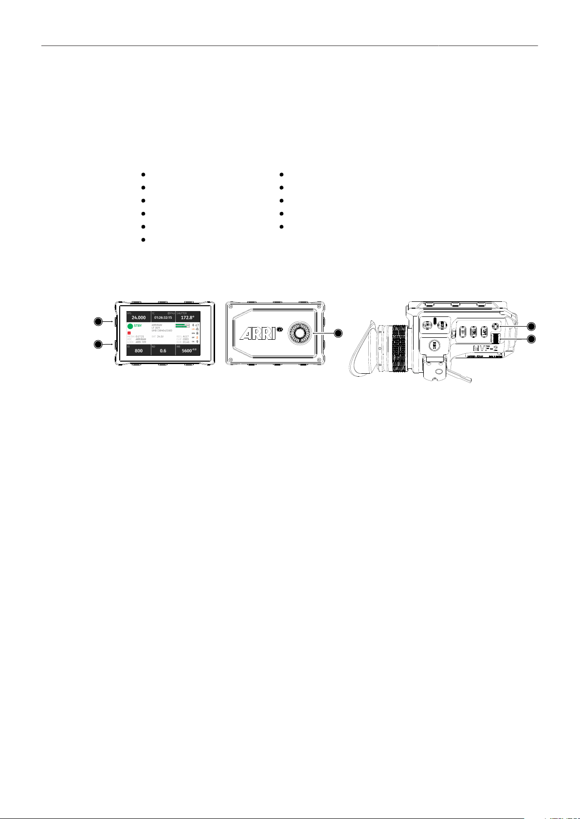
Basic Menu Operation
4
5
3
1
2
1. Press the MENU / BACK button (1) on the MVF-2 to access the camera menu.
2. Rotate the JOGWHEEL (3) or the USER WHEEL (5) to scroll up or down to select the desired
menu entry:
Entries with a ">" at the end navigate to a submenu. To navigate to a submenu press the
JOGWHEEL center or the SET button (4). To return to a higher menu level press the MENU / BACK
button.
Entries with a value allow for direct editing. To edit a value press the JOGWHEEL center or SET
button, then rotate the JOGWHEEL or USER WHEEL to select the desired value. Press the
JOGWHEEL center or SET button to confirm the change or press CANCEL to discard.
Entries with a check box allow for direct activation/deactivation. Press the JOGWHEEL center or
SET button to activate/deactivate the setting.
3. To leave the menu press the HOME / LIVE button (2).
The JOGWHEEL and the USER WHEEL + SET button provide identical functionality.
For the remainder of this manual, whenever the term JOGWHEEL is used, it refers to the JOGWHEEL
and the USER WHEEL. Whenever “press the JOGWHEEL” is used, it refers to the JOGWHEEL center
and the SET button.
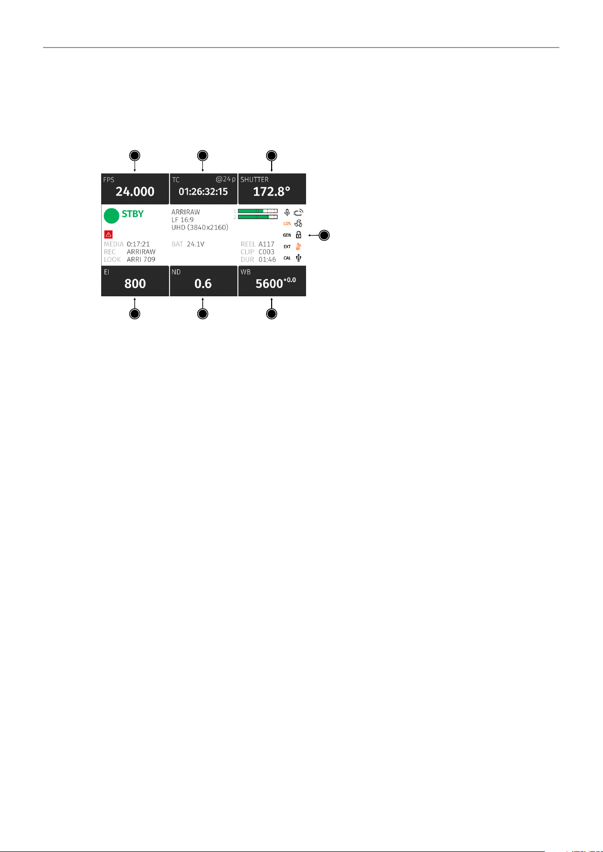
Menu Operation 40
13.1 HOME Screen
The HOME screen is the ALEXA Mini LF default screen. It shows the most important camera
parameters and gives quick access to changing them through the screen buttons:
2
3
4
6
5
1
7
1
FPS Sensor Frame Rate Settings
2
TC Timecode Settings
3
SHUTTER Settings
4
EI Exposure Index Settings
5
ND Filter Settings
6
WB White Balance Settings
7
Status Section
FPS (Sensor Frame Rate)
The FPS label shows the current sensor frame rate in frames per second. Press the FPS screen button
to adjust the sensor frame rate. The FPS label turns orange if the sensor fps does not match the project
fps rate.
Note: The maximum frame rate that can be set is dependent on the recording resolution and the codec.
TC (Timecode)
The TC label shows the current timecode value and project rate. Press the TC screen button to access
the timecode settings. The TC label turns orange if a timecode misconfiguration persists, press the TC
screen button for more information.
SHUTTER
The SHUTTER label shows the current shutter angle or exposure time. Press the screen button to
set the shutter of the sensor. Shutter angle and sensor FPS determine exposure time of the sensor in
seconds by the following equation: angle / (360° * FPS). The shutter unit can be set to display either
shutter angle (5.0° to 356.0°) or exposure time (1 s to 1/8000 s). The maximum shutter angle is limited
by the resulting exposure time (1 s max.).
EI (Exposure Index)
Shows the current exposure index. Base sensitivity for the ALEXA Mini LF is 800 ASA. Press the
screen button to adjust the exposure index in a range from 160 to 3200 ASA.
ND Filter
The ND label shows the current ND filter value of the in-camera FSND (Full Spectrum Neutral Density)
filter stage. Press the screen button to change the ND filter.
WB (White Balance)
The WB label shows the current white balance and tint. Press the screen button to set the camera’s
white balance. This is the color temperature of the light source that the camera is currently adjusted for.
In addition to the red/blue correction of the white balance, the ALEXA Mini LF can also compensate for
a green/magenta tint. This value, called CC (color compensation), is shown as an exponent of the WB
value. Positive values are marked with a "+" and negative values with a "-".
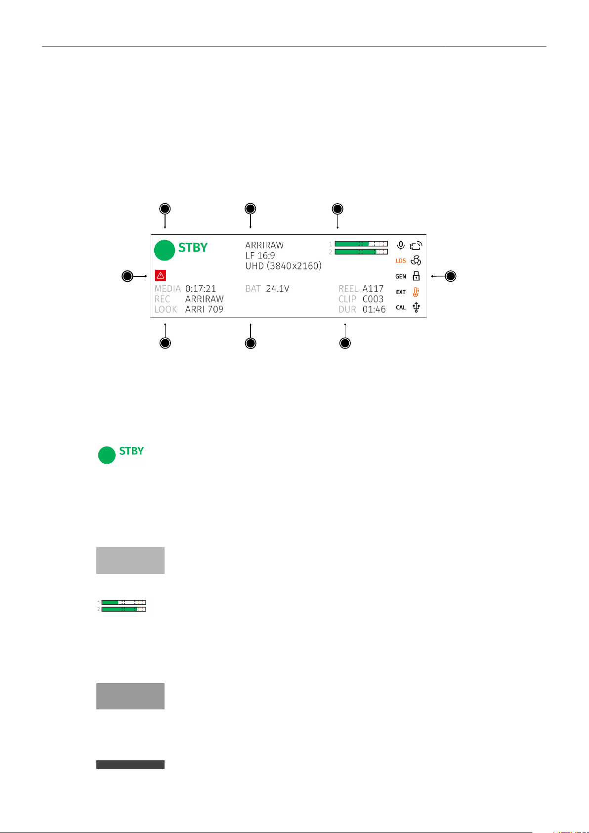
Menu Operation 41
White balance can be adjusted from 2,000 to 11,000 Kelvin (here: 5,600) in steps of 10 K for red/blue
correction. Color compensation for green/magenta tints can be adjusted in a range from -16.0 to +16.0.
Positive or negative CC color compensation values then appear as an exponent of the WB value (here:
+0.0).
Status Section
The status section on the home screen shows key data about recording, power supply, remaining
media capacity and more:
1
3
2
7
6
5
8
4
1 Camera Status 5 Clip Information
2 Codec & Recording Resolution 6 Battery Level
3 Audio Meters 7 Media Capacity & Look Setting
4 Status Icons 8 Camera Alert Icon
Camera Status
STBY
REC
PLAY
ERASE
None
Standby - ready for recording.
Recording.
Camera is in play mode.
Erasing the recording media. Active erasing disables recording.
Idle, recording not possible (e.g. no media inserted, media is full).
Codec & Recording Resolution
Currently active codec and recording resolution.
Audio Meters
The audio meters are only displayed if audio recording is enabled and show the current level of audio
channels 1 & 2. If audio recording is disabled, a crossed out speaker icon is displayed.
Black markers are shown at signal levels -20, -18, -9 dBFS for reference test tone. The yellow marker at
-5 dBFS and the red marker at -2 dBFS indicate a signal close to clipping. A red frame around the meter
indicates a clipping at the A/D stage.
Clip Information
REEL
CLIP
DUR
Current reel (camera index letter and reel number)
Name of current clip of current reel.
Duration of currently recorded clip (during REC) or last recorded clip (during STBY).
Battery Level
Current battery voltage level.
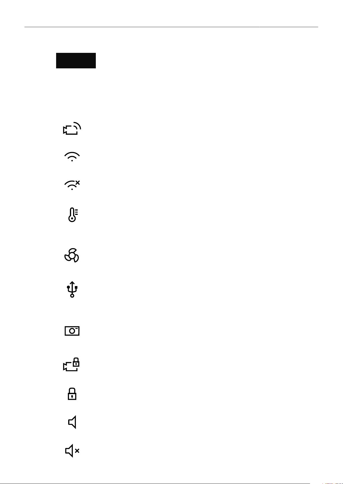
Menu Operation 42
Media Capacity & Look Settings
MEDIA
Remaining capacity of the recording media, at current FPS and codec combination, in
real time. When media capacity is below 2 minutes, capacity values start flashing.
REC
LOOK
Active recording processing (ARRIRAW or Log C)
Active Look
Status Icons
WiFi Icon. WiFi is enabled and the WiFi mode is set to Host
WiFi Icon. WiFi mode Client is enabled and the camera is connected to a network.
WiFi Icon. WiFi mode Client is enabled but the camera is not connected to a network.
Sensor Temperature Icon
Black
Orange
Red
Sensor temperature warning
Sensor temperature error
System temperature error (see MENU > Info > System Info)
Fan Speed Icon
Black
Orange
Fan speed about to increase above 20 dB.
Fan speed is higher than 20 dB.
USB Icon
Black
Gray
Orange
USB medium ready.
USB medium is read only.
USB medium is not usable.
Frame Grab Icon
Black
Orange
Frame grab is active.
Frame grab failed.
Camera Lock Icon. Camera buttons are locked.
MVF-2 Lock Icon. MVF-2 buttons are locked.
Audio Icon. Audio recording is enabled.
Audio Icon. Audio recording is disabled.
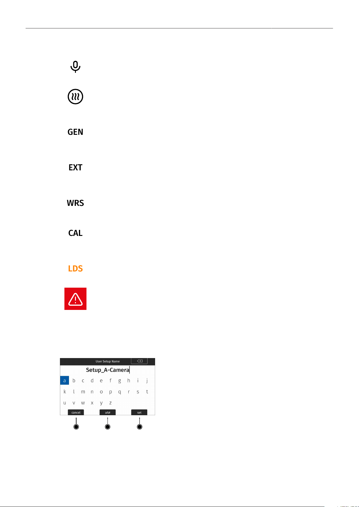
Menu Operation 43
Audio Icon. Internal microphones are enabled.
MVF-2 eyepiece heater is active.
Black
Gray
Eyepiece heater is active.
Eyepiece heater is not heating (eyepiece temperature is > 15 °C (59 ° F)).
Genlock Icon
Black
Orange
Camera is synchronized to genlock source.
Camera is not synchronized to genlock source (signal not present or unusable).
EXT Sync Icon
Black
Orange
EXT sync active.
Mismatch in EXT Sync configuration. See MENU > Alerts for more information.
Camera white radio is active.
Lens Motor Icon
Orange
Black
Lens motor calibration required.
Lens motor calibration in progress.
Indicates an error on the LDS interface.
Alert Icon. Alert is active. See MENU > Alerts for more information.
13.2 Using the On-screen Keyboard
When working with textual parameters on the camera, an on-screen keyboard allows entering text. You
can use the keyboard, for example, to enter the name of a user setup.
1
2
3
► Use the JOGWHEEL to select and confirm characters.
► Use the CLEAR button (top right) to delete the charac-
ter to the left of the cursor. Push the button and hold it to
clear the entire text.
► The aA# button (2) toggles between lower case, upper
case and numeric text entry.
► Press the SET button (3) to save the entry.
► Press the CANCEL button (1) to discard the entry and ex-
it.
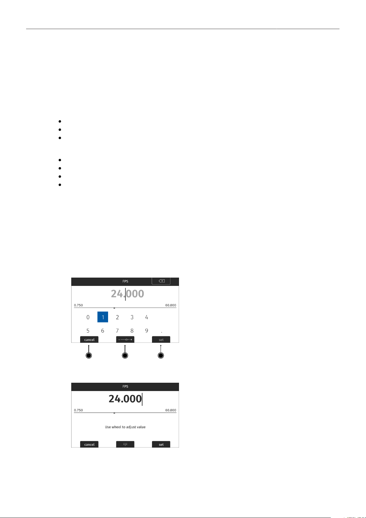
Menu Operation 44
13.3 Working with Lists and Import of Files
For certain parameters, the camera menu operates with lists that come with a default content and that
can be adjusted to the user's preference. You can ADD values to and DELETE values from these lists,
so that only project relevant values are displayed. Some lists contain values that can be edited directly
in the camera (value-based lists) while other lists consist of files that can be imported from or exported
to the USB medium (file-based lists).
Following parameters work with value-based lists:
HOME > FPS
HOME > SHUTTER
HOME > WB
Following parameters work with file-based lists:
MENU > Look > Look
MENU > Monitoring > Frame Lines > Frame Line
MENU > Setups > User Setups Installed
MENU > ECS > Lens Data > Lens Tables Installed
Adding Entries to Value-based Lists
The camera offers two methods of input when adding entries to a list. The numeric keyboard is
intended to be used for direct input of a value while the dial mode is intended to be used for fine tuning
a value (for example to fine adjust the shutter when filming monitors). The minimum and maximum
possible values are shown in the middle of the screen above the horizontal line.
1. Select HOME > FPS > ADD.
2. Use the numeric keyboard to directly enter a value. As a guide, the currently set value is displayed
in the background:
1
2
3
► Use the JOGWHEEL to select and confirm digits.
The CLEAR button (top right) deletes the digit to
the left of the cursor. Pushing the button longer
clears the entire value.
3. For fine adjustment of values press the MODE button (2) to use the dial mode:
► Rotate the JOGWHEEL to fine tune the current
value.
Press the MODE button (2) again if you want to
switch back to the numeric keyboard.
4. Press the SET button (3) to add the new value to the list, or the CANCEL button (1) to exit.
Note: the SET button will be grayed out and the value displayed in red if the entered value is out of
range.

Menu Operation 45
Working with File Based Lists
For looks, frame lines, user setups and lens tables the camera offers to import files from the USB
medium as well as from a default list. To import files from a USB medium into the camera, the USB
medium needs to be prepared with a certain folder structure, see "User Storage Handling", page 47
for more information. Files are imported from these USB folders:
File Type
Look Files
Frame Lines
User Setups
Lens Data Archive (LDA)
Corresponding USB Folder
ARRI/A-MINI-LF/LOOKFILES
ARRI/A-MINI-LF/FRAMELINES
ARRI/A-MINI-LF/SETUPS
ARRI/A-MINI-LF/LDA
Note: The maximum file name length of user files is 64 characters including the file extension. User files
with a name exceeding 64 characters cannot be displayed in camera lists. The instructions below use
the import of frame lines as an example.
Import Files from USB
1. Insert the USB medium into the camera.
2. Select MENU > Monitoring > Frame Lines > Frame Line > ADD.
3. Select the desired frame line file from the USB list.
4. Press the IMPORT button or the JOGWHEEL to add the frame line to the frame lines list.
Import Files from Defaults
1. Select MENU > Monitoring > Frame Lines > Frame Line > ADD.
2. Select DEFAULTS.
3. Select the desired frame line file from the defaults list.
4. Press the IMPORT button or the JOGWHEEL to add the frame line to the frame lines list.
Deleting List Entries
1. Select HOME > FPS.
2. Scroll to the entry to be deleted.
3. Press the DELETE button.
The selected entry is marked for delete.
4. Press the DELETE button again to delete the selected entry or rotate the JOGWHEEL to cancel.
Maximum Entries per List
All lists have a maximum number of entries they can hold. Whenever a list is full, the ADD button is
grayed out and a message is shown. You need to delete entries from the list first in order to add new
ones. The following table lists the maximum number of entries for each type of list:
List
FPS
SHUTTER
WB
Looks
Frame Lines
User Setups
LDA
Maximum no. of Entries
16
16
16
50
100
20
200
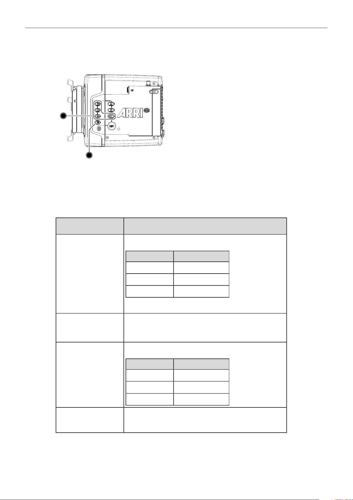
Menu Operation 46
13.4 Function Button FN
1
2
The camera's left side is equipped with the function
button FN (1) and six camera buttons of which four are
labelled with additional icons (2). These four buttons
can act as regular user buttons or in combination with
the FN button access common camera functions.
Camera Buttons to Access Common Camera Functions
By default, the camera buttons function as user buttons. In combination with the FN button they offer
shortcuts to common camera functions.
Following camera functions can be accessed:
Function Button & Camera
Button
Function
FN + 1
Toggles the overlay menu in the viewfinder and the SDI outputs. In the
overlay menu, the camera buttons control the following functions:
Camera Button Function
1 Select backward
2 Select forward
3 Access / Confirm
For more information, see "Overlay Menu", page 77.
FN + 2
Prepares recording media erase and shows a message on MVF, flip-out
monitor and SDI outputs. To confirm the erase, press camera button 3
twice. Any other button can be pressed to cancel the action. After the erase
has finished, press any button to clear the status message.
FN + 3
Starts/stops playback from the recording medium. During playback, the
camera buttons control the following functions:
Camera Button Function
1 Skip backward
2 Skip forward
3 Play / Pause
FN + 6
Toggles WiFi on/off.
When pressing (just) the FN button, the status LED of button 6 reflects the
current WiFi status (LED on = WiFi enabled).

Menu Operation 47
► Press and hold the FN button (1), then press a camera button (2) to access the function. You can
also press the FN button twice within 0.5 seconds to bring the camera buttons into FN selection
mode for two seconds. During these two seconds the FN button status LED is lit (indicating active
FN selection mode) and pressing a camera button will access the function behind it.
13.5 User Storage Handling
The ALEXA Mini LF saves data such as user setups, frame grabs and system logs to a USB memory
stick. Firmware, additional frame lines and ARRI Look File 2 files can be loaded onto the camera using
the USB memory stick.
The camera only supports FAT formatted USB memory sticks with MBR partition table and with a
maximum capacity of 16GB. A special folder structure is used in order to work with the camera. This
folder structure can be prepared in camera and the folder preparation will not alter existing folders and
files on the USB medium.
The USB slot is located at the back of the camera below the recording media slot. To access the USB
slot, open the media door.
User Storage Status on HOME screen and in Camera Menu
The USB icon in the status section on the HOME screen of the user interface reflects the USB medium
status:
Black: usable
Gray: read only
Orange: not usable
Prepare User Storage for Use
The camera can only load files from a correctly prepared USB medium with the required folder
structure. Preparing the folder structure on the USB medium within the camera will not alter existing
folders and files on the USB medium.
1. Open the media door and insert the USB medium.
2. Select MENU > Media > Prepare USB Medium.
3. Press CONFIRM to prepare the folder structure.
The USB memory stick is now ready for use with the camera.
The required folder structure for use in the camera is listed below, and can also be created manually on
a computer:
ARRI/A-MINI-LF/ FRAMELINES
GRABS
LDA
LICENSES
LOG
LOOKFILES
SETUPS
SUP
SENSOR
for frame line imports to camera
for grabbed still frames
for lens tables imports/exports
for license file installation
for exported camera and update logfiles
for look file imports/exports
for imports/exports of user setup files
for update file installation
for import/export of User Pixel Mask files and export of frame grabs for
User Pixel Mask creation
Remove User Storage
You can remove the USB medium from the camera without unmounting it.

Menu Operation 48
13.6 Info Screens
The INFO screens provide detailed information about the current state of the camera system.
► Select MENU > Info.
The INFO list contains the following entries.
Version Info
System Info
Maximum FPS Info
Media Info
USB Info
Network Info
Lens Info
User Button Info
EXT Sync Info
Export HW Info File
Export Logfiles
Export Update Logfiles
Version Info
The version info screen displays the software versions of the camera and connected components:
Software
Revision
FPGA
MVF-2 Software
Lens Mount Software
The camera software version.
Revision of camera software version.
Firmware version of active FPGA (indicated by number in brackets).
Software version of MVF-2 (only shown if connected).
Software version of lens mount.
System Info
The system info provides detailed information about the camera:
Time + Date
Camera Serial No.
Operating Hours
Sensor Temperature
Sensor Temp. State
Camera Temp. State
Current system time and date of the camera.
Serial number of camera.
Total operational time of the camera in hours:minutes.
Current temperature of image sensor.
Rates the sensor temperature according to OK, warning, or error.
Rates the camera temperature according to OK, warning, or error.
Maximum FPS Info
This screen gives detailed information about the maximum sensor frame rate:
Sensor FPS
Codec FPS
Media FPS
Maximum sensor FPS with the current recording resolution.
Maximum sensor FPS with the camera's current codec setting.
Maximum sensor FPS supported by the inserted recording media with the current recording
codec and camera's resolution setting.
Media Info
This screen shows information on the recording media:
Status
Model
SN#
FW Version
Size
Clip Count
Status of the recording media.
Name/model of the recording media.
Serial number of the recording media.
Firmware version of the recording media.
Total storage size of the recording media.
Amount of clips on the recording media.

Menu Operation 49
USB Info
This screen shows information on the USB storage. The number entries consist of two numbers, the
number of files on the USB medium and the number of files recognizable by the camera.
Status
Storage Free/Total
Frame Line Files
License Files
Look Files
Setup Files
SUP Files
LDA Files
Status of USB medium.
Free and total available storage on USB medium in megabyte.
Number of frame line files on USB medium.
Number of license files on USB medium.
Number of look files on USB medium.
Number of user setup files on USB medium.
Number of SUP (software update package) files on USB medium.
Number of LDA (Lens Data Archive) files on USB medium.
Network Info
The network info screen shows Ethernet and WiFi related information:
WiFi Network
WiFi IP
LAN IP
Web Remote
Name of connected network (client mode).
IP address of the camera via WiFi.
IP address of the camera via Ethernet.
URL address of camera remote control website.
Lens Info
The lens info screen shows information on the attached lens:
Lens Type
Model
Serial No.
Focal Length
Focus
Iris
Type of lens (LDS, Cooke, ENG, EF...)
Lens model name according to manufacturer.
Serial number of lens.
(Current) focal length of lens in mm.
Current focus distance of lens.
Current iris value of lens.
User Button Info
The user button info screen lists the functions assigned to the User Buttons of the camera body and the
MVF-2 .
EXT Sync Info
The EXT Sync info screen shows the system status of all cameras in the EXT sync setup. It lists the
serial number, the camera ID prefix, the battery voltage and the status of the master and the slave
camera(s) in the setup.
Export HW Info File
HW (HardWare) info files are required to generate licenses in the ARRI License Shop or may be
requested by camera service to get detailed information on the camera's hardware and components.
The HW Info file will be exported to the USB medium in the ARRI/A-MINI-LF/LICENSES folder.
Export Logfiles
Logfiles help camera service to analyze potential problems. In normal circumstances, logfile export is
not required.
Logfiles will be exported to the USB medium in the ARRI/A-MINI-LF/LOG folder.

Menu Operation 50
Export Update Logfiles
Similar to regular logfiles, update logfiles help camera service to analyze problems that occured during
the update process. In normal circumstances, exporting update logfiles is not required.
Update logfiles will be exported to the USB medium in the ARRI/A-MINI-LF/LOG folder.
13.7 Alerts Screen
Alert messages communicate critical system states to the user. They require immediate attention and
remain active until the state returns to normal.
A red exclamation mark, visible on the home screen, the flip-out monitor and the EVF
and SDI status overlays indicates active alert messages.
► Select MENU > Alerts to read the alert message.

Main Parameters 51
14 Main Parameters
The following chapter lists the most important parameters of the camera.
14.1 Project Settings
The project settings menu contains settings that should be configured at the beginning of each project
and can be found at MENU > Recording > Project Settings.
Project Rate
The project rate sets the timecode timebase and the playback frame rate. The timecode timebase
determines how many frames the timecode counts per second. The playback frame rate determines the
frame rate at which clips will be played back.
Select to set the timecode timebase and the playback frame rate. The timecode timebase determines
how many frames the time code counts per second. The playback frame rate determines the frame
rate that clips will be played back at. Changing the project frame rate will automatically also change the
sensor frame rate and the SDI frame rates to the same value. It is still possible to have different frame
rates for these settings by changing the sensor frame rate or the any of the SDI frame rates individually.
1. Select MENU > Recording > Project Settings > Project Rate.
The following project rates are available:
Project Rate
23.976p
24p
25p
29.97p
30p
48p
50p
59.94p
60p
Scan Format
Progressive
Progressive
Progressive
Progressive
Progressive
Progressive
Progressive
Progressive
Progressive
Sensor Real-time Recording
23.976 fps
24 fps
25 fps
29.97 fps
30 fps
48 fps
50 fps
59.94 fps
60 fps
2. Set the desired project rate.
Changing the project rate will match sensor and SDI fps setting to the project rate. A pop up window
will inform you about this.
Next Reel Count
The next reel count ets the reel number assigned to the next new media used for internal recording. A
new media is either a blank media or a media with reels of other ALEXA Mini LF cameras. The camera
automatically advances the reel number every time new media is formatted on the camera. The reel
number is reflected in clip names and is displayed on the home screen.
1. Select MENU > Recording > Project Settings > Next Reel Count.
2. Set the desired next reel count.
Camera Index
Give each camera a unique camera index so that you can identify the individual camera unit (A, B, C
etc.) in clip and reel names. For more information please see "File Naming Scheme", page 70.
1. Select MENU > Recording > Project Settings > Camera Index.
2. Set the camera index in the range from A to Z.

Main Parameters 52
Camera Index Color
Set the color of the camera index letter displayed in the status info of the SDI outputs (e.g. to match it to
the color coding of your cameras).
1. Select MENU > Monitoring > SDI > SDI Processing > Overlays > Status Components > Camera
Index Letter to display the camera index letter in the SDI status info.
2. Select MENU > Recording > Project Settings > Camera Index Color.
3. Set the camera index color.
Camera ID Prefix
You can define the first character of the Camera ID. The Camera ID is a Base36 representation of
the camera serial number and part of each clip's name. It allows you to match each clip to a specific
camera. You set the camera ID prefix individually on each camera. For more information please see
"File Naming Scheme", page 70.
1. Select MENU > Recording > Project Settings > Camera ID Prefix.
2. Set the camera ID prefix in the range from A to Z.
Lens Squeeze Factor
The lens squeeze factor determines the factor that is used for anamorphic desqueeze on EVF/Monitor
and SDI. This value is also written into the metadata of the clip and allows video players and editing
software to automatically desqueeze clips that have been shot with anamorphic lenses.
1. Select MENU > Recording > Project Settings > Lens Squeeze Factor.
The following lens squeeze factors are available:
Factor
1.00
1.25
1.30
1.50
1.65
1.80
2.00
Usage
for all spherical lenses
e.g. Ultra Panavision 70 Lenses
e.g. Vantage Hawk Lenses
e.g. P+S Technovision, Iscorama, Kowa
e.g. Panavision Ultra Vista Anamorphic lenses
e.g. Cooke Anamorphic/i Full Frame Plus lenses
for classic 2x squeeze CinemaScope S35 lenses
2. Set the desired lens squeeze factor.
The selected lens squeeze factor is automatically applied to EVF/Monitor and the SDI outputs.
For more information please see "Anamorphic Desqueeze", page 81.
14.2 Sensor Frame Rate
Setting the Sensor Frame Rate
1. Select HOME > FPS.
The sensor FPS list is displayed.
2. Select a frame rate from the FPS list or add and select a custom frame rate.
The sensor fps list is displayed.
3. Using the jogwheel, scroll to the desired value/entry.
4. Press the jogwheel to set the new value.

Main Parameters 53
14.3 Shutter
Changing the Shutter
1. Select HOME > SHUTTER.
The shutter list is displayed.
2. Select a shutter value from the list or ADD a custom shutter value to the list.
3. Set the desired shutter value.
Adjusting the Shutter for Filming a Monitor
1. Set the shutter unit to Shutter Angle.
2. Go to HOME > SHUTTER > ADD.
3. Select the third digit (single degrees).
4. Adjust the shutter value until the monitor image flickers the least.
5. Select the fourth digit (sub-degrees).
6. Fine-adjust the shutter value until there is no more flicker visible.
7. Press SET to add the shutter value to the list.
Shutter Unit
The camera offers to set the shutter unit.
1. Select MENU > System > Shutter Unit.
Two options are available:
Shutter Angle Converts exposure time into the angle of a virtual rotating mirror shutter as
in film cameras. A fixed angle creates varying exposure times with varying
frame rates. You can set angles from 5.0 to 356.0 degrees.
Exposure Time Shows the effective sensor exposure time. With varying frame rates, it re-
mains identical and can be set from 1/1 to 1/8000 seconds.
Note: Maximum exposure time with a given frame rate is 1/fps, with a lim-
it of 1/1 seconds. When the selected exposure time is no longer possible
because you changed the frame rate, the camera uses the longest expo-
sure time possible. For example, if you configured 1/25 s at 25 fps and you
change the sensor fps to 50, the camera will use 1/50 s.
For a constant exposure time over a range of used frame rates, set it to
1/(highest used frame rate).
2. Set the desired shutter unit.
Note: The camera sensor is optimized for exposure times shorter than 1/24 s and image artifacts like
individual overexposed pixels can appear when using longer exposure times.
14.4 Exposure Index
The Exposure Index (EI) is the applied sensitivity of the camera. The ALEXA Mini LF has a base
sensitivity of 800 ASA. This means that the dynamic range is almost evenly distributed above and
below neutral gray with low noise in the shadows and clean, smooth clipping behavior in the highlights.
Due to its high dynamic range, the camera’s sensitivity can be set from 160 to 3200 ASA in steps of 1/3
stops while maintaining high image quality.
Applying the exposure indexes at the extremes of the range will nonetheless have an influence on the
images. At low exposure indexes, such as 160 ASA, the dynamic range below neutral gray increases,
reducing noise even further. At the same time, the dynamic range above neutral gray is slightly
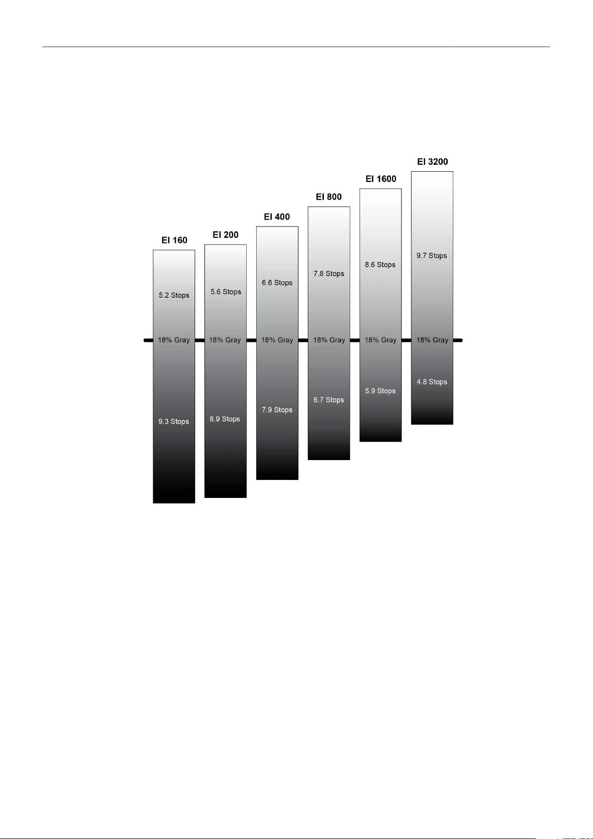
Main Parameters 54
reduced. Highlight clipping itself is not influenced by this, but the shoulder of the gamma curve will get
slightly steeper, reducing the smoothness of the change from almost overexposed to overexposed. At
high exposure indexes, such as 1600 ASA, the images behave in the opposite way. Noise is increased,
which makes it important to judge shadow detail, while there will be even more headroom in the
highlights.
Setting the Exposure Index
1. Select HOME > EI.
2. Set the desired exposure index.
14.5 ND Filter
Internal FSND Filters
The ALEXA Mini LF has a built-in motorized and sealed filter stage for Full Spectrum Neutral Density
filters (FSND) with densities of 0.6, 1.2 and 1.8 (and an optical clear filter). In comparison to IRND
filters, which have an uneven spectral behavior, or to an ordinary ND filter, which opens up at about 675
nm, the FSND filters offer a true, even reduction over the whole spectrum. This prevents artifacts from
infrared wavelengths and the need for additional IR filters.
ALEXA Mini LF uses FSND (Full Spectrum Neutral Density) filters, which are linear across the full
spectrum of the camera sensor. This prevents artifacts from infrared wavelengths and the need for
additional IR filters.

Main Parameters 55
Selecting the ND Filter
The currently set ND filter value is displayed on the HOME screen and in the status info of the
viewfinder and the SDI outputs. The camera offers various ways to adjust the ND filter:
ND Filter screen
Camera user buttons
WCU-4 user buttons
ARRI Master Grips and Operator Control Unit OCU-1 user buttons
Web remote
Applications communicating with the camera through the Camera Access Protocol (CAP).
Selection in camera menu
1. Select HOME > EI > ND.
Following settings are available:
ND - (Clear)
ND 0.6
ND 1.2
ND 1.8
2. Set the desired ND filter.
14.6 White Balance
White Balance (WB) is the color balance of the camera that should be matched to the color temperature
of the light in use. White balance is a red-blue adjustment of the image. To adjust the green-magenta
balance, use the color compensation (CC) adjustment. For example, a fluorescent source will have
peaks in its spectrum that cannot be corrected with red-blue white balance alone. The CC shift can
correct these peaks up to a full green or full magenta gel. One step of CC shift is equal to 035 Kodak
CC values or 1/8 Rosco values.
There are three methods for setting the white balance:
White balance presets
Custom white balance
Automatic white balance
Preset and Custom White Balance
1. Select HOME > WB.
The WB list is displayed, offering the following default values:
3200 K +0.0 CC
4300 K +0.0 CC
5600 K +0.0 CC
7000 K +0.0 CC
2. Select a value from the list or ADD and select a custom white balance.
For information on how to add entries to a list please see "Working with Lists and Import of Files",
page 44.

Main Parameters 56
Automatic White Balance
Automatic white balance calculates the white balance based on the camera's live image and overwrites
the active white balance value. The result is stored as first entry in the WB list. Automatic white balance
can be triggered through a dedicated button in the white balance screen or through a user button
assigned with Auto WB. For information on how to assign functions to user buttons please see "User
Buttons", page 107.
1. Select HOME > WB.
2. Press Auto WB.
The EVF and the SDI outs display an image overlay showing the center area used for white
balance calculation.
3. Press the Auto WB button again within one second to execute automatic white balance.
The calculated white balance is set and stored as first entry in the white balance list.
Note: Under- or overexposed images may cause the automatic white balance to fail. Always trigger
automatic white balance with properly exposed images.
14.7 Timecode
Timecode ensures that every image of recorded footage can be identified with a unique value and
synced with corresponding media, such as sound or the second camera in a 3D application. When
used with other metadata, such as reel names, all recorded media retains its unique identity.
The following are two ways of using timecode on a production:
Free Run Timecode, Time of Day
Use: This format is often used on multi camera productions with sync-sound, i. e. the sen-
sor frame rate matches the project rate, sound and image timecode match and allow
for easy syncing in post.
Setup: The sound department acts as the timecode master, and generates timecode which
uses the time of day as a value, and a time base matching the project frame rate.
Twenty-four hours of time will translate into twenty-four hours of timecode. Timecode
is fed to the camera via the TC connector. The project fps setting must match both the
sensor frame rate and the time base of the external timecode signal.
The camera can be set to timecode mode jam sync, in which it samples the timecode
value once from the timecode connector and then continues counting based on its
own high precision crystal clock. The timecode source can be disconnected from the
camera after jamming in jam sync mode. This mode ensures stable timecode with an
offset of less than one frame for each eight hours, after which the camera has to be
re-jammed.
Alternatively, the camera can be set to timecode mode regenerate (regen). In regen
mode, the camera uses the timecode value of the external timecode source. This en-
sures correct timecode for an infinite duration, but the timecode source must remain
connected to the camera. Please note that while recording the camera ignores exter-
nal timecode and is using its internal clock to avoid potential timecode jumps, which
can occur due to connection problems such as a faulty timecode cable for example.
Variations: If shooting starts close to midnight, the timecode may be started with an offset time of
day to prevent a rollover at midnight.
Restrictions: Free run timecode is only possible, if the camera is running at sync-sound speed. If
the camera is over- or undercranking, the timecode frame rate will no longer match
the sensor frame rate, and timecode values would either be duplicated or dropped. To
prevent this, the camera will automatically switch to run mode rec run when the sen-
sor frame rate is changed.

Main Parameters 57
Rec Run Timecode
Use: Rec run timecode is often used on single camera productions that are either MOS or
use a dumb slate to sync picture and sound. Record run timecode guarantees contin-
uous timecode on all recorded data. Record run timecode also works with over- and
undercranking.
Setup: The timecode run mode must be set to rec run, the mode to regenerate. Timecode
counts up only during recording, by one frame for each image generated by the sen-
sor. The timecode counts at the project frame rate set on the camera. Normally, the
timecode hour value advances by one hour for each new reel, using only hours 01-20
for reel 1-20, and then restarting at hour 01 for reel 21.
Variations: Rec run timecode might be used for off-speed work on productions that use external
timecode sources for all sync sound.
Restrictions: None
Setting the Timecode Manually
1. Select HOME > TC > EDIT.
2. You have the following options:
For TC = 00:00:00:00: Press RESET.
For TC = current system time: Press SET TO TIME.
Via jogwheel, you can change each value. Scroll up or down to increase or decrease the value.
Press the jogwheel to select the next digit pair.
3. Press DONE to save the changes. Cancel with BACK.
Note: EDIT is available only when timecode is in preset mode.
Note: You can edit timecode in preset mode only.
Timecode Run Mode
1. Select HOME SCREEN > TC > Options > Run Mode.
You have the following options:
Rec Run Timecode increases during recording only. The timecode value increases with
every frame generated by the sensor while recording.
Free Run Timecode increases with every new frame generated by the sensor, indepen-
dently from recording.
Note: Free run is only possible if the sensor fps equals the project fps (i.e.
shooting sync speed). Otherwise, the camera temporarily switches to rec run.
The free run timecode continues to count in the background.
When you set the sensor frame rate back to equal the project frame rate, the
timecode will synchronize itself to the free run timecode again.
If you synchronized your camera to an external signal while it was in free run,
you can shoot offspeed shots in rec run timecode and return to sync speed af-
terwards. The camera will return to free run timecode and seamlessly recon-
nect to the previously synchronized timecode.
Timecode Mode
► Select HOME > TC > Options > Mode.
You have the following options:

Main Parameters 58
Regen Depending on the timecode run mode, regen behaves differently:
Run mode rec run: The camera determines the timecode of the last frame of
the last recorded clip and increments it by one for the next clip. This ensures
consecutive timecodes for a sequence of clips.
Run mode free run: The timecode source should be connected to the camera
permanently. The camera continuously reads the timecode signal at the time-
code connector as long as it is present. Upon disconnection or loss of signal,
the camera continues counting on its own, but will indicate the missing signal
through an orange exclamation mark on the TC button on the home screen.
When the external signal is reconnected, the camera uses the value of the ex-
ternal signal again. Regen mode will disable manual editing of the timecode.
Preset The camera uses its internal counter.
Jam Sync The camera samples the timecode value and simultaneously tunes its inter-
nal timecode clock to match the clock of the timecode source. During this pro-
cedure, the timecode display on the home screen, on the timecode menu
screen as well as on the status overlays is flashing. Jamming has finished
when the timecode display stops flashing, then the timecode source can be
disconnected. The camera continues counting based on its own high pre-
cision crystal clock now. This mode ensures stable timecode with a drift of
less than one frame over eight hours, after which the camera has to be re-
jammed.
Note: Due to the tuning mechanism, jamming the camera might take up to 30
seconds and a timeout is issued if tuning could not be completed after 60 sec-
onds.
Regen Source
Based on the timecode run mode, the camera determines the timecode regen (regenerate) source
automatically. If the run mode is set to Free run, it regenerates timecode from the timecode input
connector. If set to Rec run, it regenerates timecode from the last clip of the recording media by
continuing seamlessly from the last active value.
► View HOME > TC > Options > Regen Source.
The regen source is displayed. The following settings are possible:
LTC In timecode is continuously read from the TC connector.
Media timecode from the last clip of the active recording card by continuing seam-
lessly from the last active value.
EXT when camera is set to EXT sensor slave or EXT settings slave)
Timecode Offset
You can apply an offset to LTC input signals to compensate for timecode offsets in external devices.
1. Select HOME > TC > Options > TC Offset.
2. Adjust the timecode offset in the range of -20 to +20 frames.
NOTICE
The camera's internal battery will keep the timecode and timecode tuning values for about 10
minutes after the power source was disconnected.
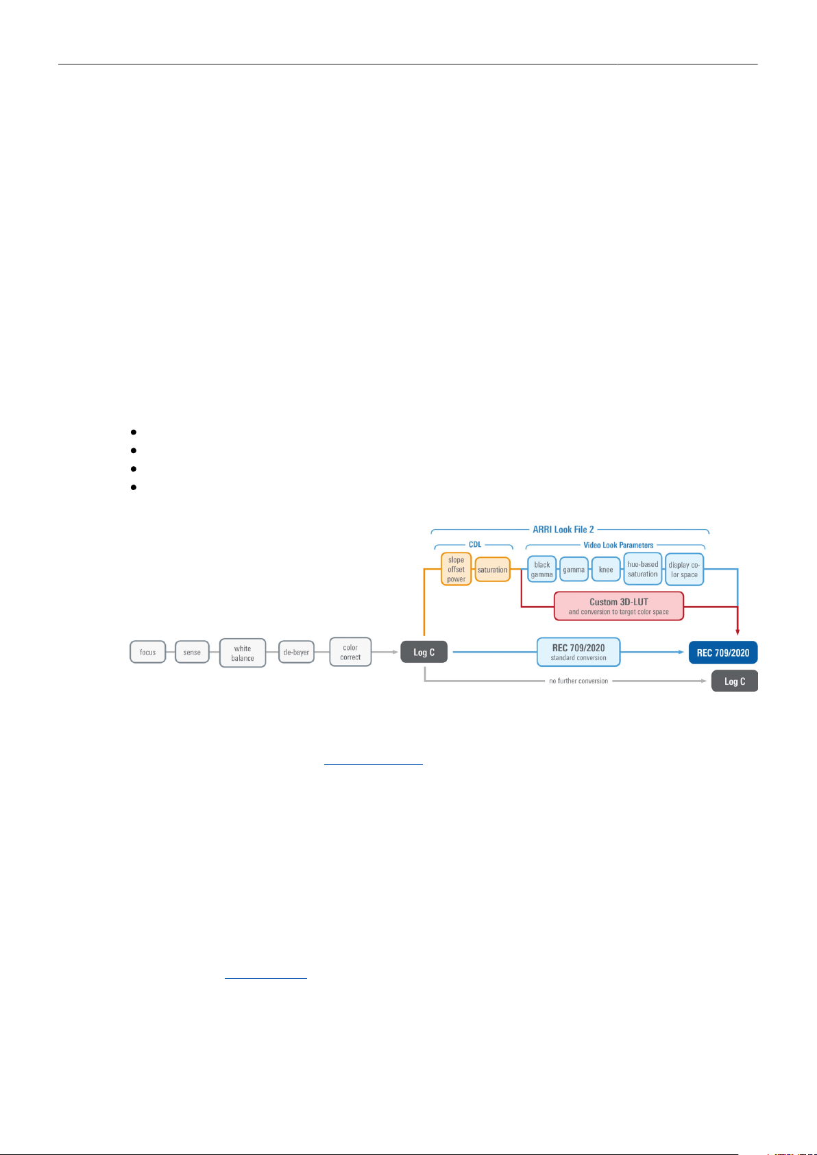
Look Settings 59
15 Look Settings
ARRI Look File 2
ARRI Look File 2 files are a way for the user to alter the parameters the camera uses when converting
the sensor image data to a video color space. This can be described as applying a custom "look" to the
different image output paths. With the ALEXA Mini LF the ARRI Look File 2 files can be applied to the
monitoring paths and is included in the clip as metadata only (nondestructive workflow).
The ARRI Look File 2 can influence an image, respectively a shot or scene. For a good overview
of the color controls, follow the image path of the camera in the scheme below: In the first step the
sensor data is balanced for the light source’s color temperature (white balance). This ensures a neutral
representation of the R, G, and B values of objects. In the second step, a Log C image is created. The
Log C transform is controlled by the exposure index (EI), which is (like the white balance) not part of
the look. All following alternations to the color are based on a Log C image which is also the result if the
whole look mechanism is bypassed.
Inside an ALF-2 file, various combinations are possible:
Color Decision List (CDL) only
CDL and Video Look Parameters
CDL and 3D LUT
3D LUT only (e.g. conversion to REC 709 or custom LUT)
A look file can be created in the ARRI Color Tool as a completely new look, using a 3D LUT created
in a grading session or you can edit the look live on set using a live-grading application like Filmlight
Prelight or Pomfort Livegrade. For a more detailed look at a specific live-grade workflow, please visit the
manufacturer website.
These tools connect to the camera’s look controls via the Camera Access Protocol (CAP). The current
look is recorded as metadata with the push of the record-button and rewritten with its latest values
when the recording is stopped, and the file closed. This guarantees to have the latest “starting look” if a
power-out interrupts the recording and to keep the subtle changes done during the take.
After recording, backup and data transfer the look can be extracted from the clip’s file header using the
ARRI Color Tool again. This way the look can travel to post production as an ARRI Look File 2 or as a
3D LUT.
For more information about the ARRI Look File 2, please refer to the ARRI Look File 2 white papers,
available in the White Papers section on the ARRI website.

Look Settings 60
Camera Default Look Files
The ALEXA Mini LF comes with several pre-installed ARRI Look File 2 files:
Look Description
ARRI 709 Renders the video image according to the ITU.R-BT709 standard, for most accurate col-
or reproduction on standard broadcast monitors.
ALEXA Classic 709 Matches the color reproduction of ALEXA Mini to the ARRI ALEXA.
ARRI 2100 HLG 1K 200 HDR look file. Renders an image for a HLG (Hybrid Log Gamma, ITU-R BT.2100) moni-
tor. It is assumed that the monitor has maximum luminance of 1000 cd/m
2
. In this case,
the image will look the same as when the PQ look is used with a PQ monitor.
ARRI 2100 PQ 1K 200 HDR look file. Renders an image for a PQ (SMPTE 2084, ITU-R BT.2100) monitor. The
maximum luminance is 1000 cd/m
2
, which is a PQ level of 75%. The diffuse scene white
(2.5 stops above the gray card) will appear with a luminance of 200 cd/m
2
.
Commercial Renders the image brighter for smoother skin tones.
Landscape Applies a steeper contrast curve to the image.
LCC 709 Low Contrast Curve look that contains a custom tone map curve that creates a video im-
age with lower contrast compared to the standard REC 709 output. As a result, the im-
age holds as much dynamic range information as possible, without using Log C encod-
ing.
TV-neutral An ARRI 709 like look, which is more saturated in colors with slightly lower blacks.
TV-warm Same as TV neutral, just with a slightly warmer look overall.
Vibrant Boosts color saturation except for red and yellow (skin tone protection).
Setting the Look
You can choose to use just go with REC 709 look, use another a pre-installed look or import custom
looks into the camera. Additional ARRI Look File 2 files can be added to the camera from the USB
medium. The ARRI Look File 2 files must be copied into the ARRI/A-MINI-LF/LOOKFILES folder on the
USB medium.
1. Select MENU > Look > Look.
2. Select and set a look from the list or import and set a custom look.
The selected look will be included in the metadata of recorded clips.
3. Apply the look to the desired image outputs, see next chapter for more information.
Playback and ARRI Look File 2 files
During playback, the camera makes a distinction between clips recorded in ARRIRAW, Log C, or Look
processing. When a clip recorded in ARRIRAW or Log C is played back and an output is configured for
Look processing, the look will be applied to this output. Please note that this is the currently enabled
ARRI Look File 2, as the camera does not take into account which ARRI Look File 2 was active when
the clip was recorded. It is the responsibility of the user to make sure the correct ARRI Look File 2 is
applied during playback. When a clip recorded with Look processing is played back, no ARRI Look File
2 will be applied by the camera during playback. For the duration of that clip, ARRI Look File 2 files will
be disabled.

Look Settings 61
15.1 Processing and Color Spaces
Log C
The Log C curve is a logarithmic encoding of the scene, meaning that the relation between exposure
measured in stops and the signal is constant over a wide range. Each stop of exposure increases the
signal by the same amount. The overall shape of the Log C curve is similar to the exposure curves of
film negatives. Because of fundamental differences between a sensor and negative film, however, the
color characteristics remain different.
Log C actually is a set of curves for different EI values/ASA ratings. Each curve maps the sensor signal,
corresponding to 18% gray scene luminance, to a code value of 400 in a 10 bit signal. A 10 bit signal
offers a total code value range of 0 to 1023. The maximum value of the Log C curve depends on the
set EI value. The reason is quite simple: When the lens is stopped down, by one stop for example
and the EI setting is increased from, say, 800 to 1600, the sensor will capture one stop more highlight
information. Since the Log C output represents scene exposure values, the maximum value increases.
Configuration of EVF/Mon. and SDI Processing
1. Select
MENU > Look > EVF/Mon. Processing.
MENU > Look > SDI 1 Processing.
MENU > Look > SDI 2 Processing.
Following processing options are available:
Log C Based on the Cineon format for output to film print or digital intermediate, this
logarithmic processing requires color grading in postproduction. On standard
broadcast monitors, Log C images appear flat and desaturated. Proper dis-
play, dailies and editing proxies require a conversion look-up table (LUT).
Look Select to apply the look set in MENU > Look > Look to the output path.
Applies a video display processing to camera images. The default ARRI 709
look complies with the ITU.R-BT709 standard for display on standard broad-
cast monitors.
ALEXA Classic
709
Creates a Rec 709 equivalent image in the same way that it is processed in
the ALEXA Classic product line. This setting may be used when the selected
Look file alters the image too drastically, but a Log C image would be too flat
for monitoring.
2. Select the desired processing for each output.
The currently set processing is displayed in the status info of EVF/Mon. and SDI outs.
Configuration of SDI Color Space
1. Select
MENU > Look > SDI 1 Color Space.
MENU > Look > SDI 2 Color Space.
The color space options for the SDI outputs are:

Look Settings 62
REC 709 Material recorded in Rec 709 (short for ITU Recommendation BT.709) has a
display specific encoding. The purpose of a display specific encoding is to im-
mediately provide a visually correct representation of the camera material,
when it is screened on a certain display device. This is achieved by mapping
the actual contrast range of the scene into the contrast range that a display
device can reproduce. Examples of display specific encodings are Rec 709
for HDTV screens or DCI P3 for Digital Cinema Projectors. On the downside,
a display specific encoding puts some limits on the options for a colorist.
REC 2020 Rec 2020 is a wider color space than Rec 709, which is the current industry
standard for HD. Rec 2020 promises more brilliant images, though only new
display technology is able to show these. Traditional Rec 709 displays (like
TVs or ordinary computer displays) can not display Rec 2020.
While Rec 709 is the encoding color space for HDTV, Rec 2020 is the encod-
ing color space for UHD. The primary colors lie on the spectral locus and it
is thus possible to have more saturated colors in images. It does not mean,
however, that all colors look more saturated. When properly converted, Rec
709 images will look exactly the same when displayed on a Rec 2020 dis-
play. Rec 2020 is an encoding standard. A TV or display may not support the
full gamut. Nevertheless, it will correctly display the colors within its physi-
cal gamut. To get the “Premium” logo of the UHD Alliance, for example, a TV
needs to support a minimum of 90% of the P3 gamut.
2. Select the desired color space.
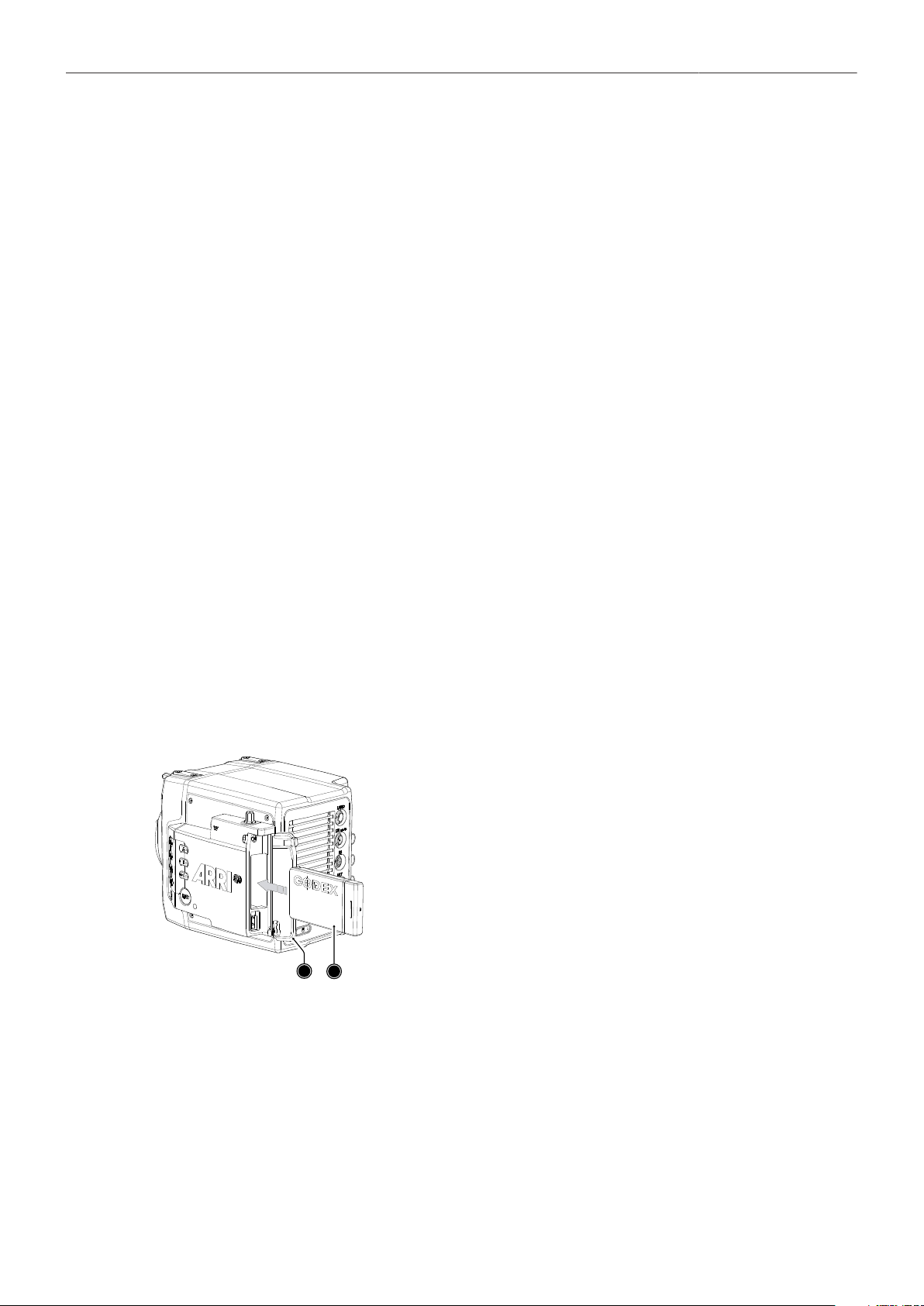
Recording 63
16 Recording
16.1 Recording Media Handling
About Codex Compact Drives
Compact Drives have been specifically designed for the small form factor of the ALEXA Mini LF,
using new flash technology in a miniaturized casing. The drives offer data rates of up to 8 Gbps and
support all image and recording formats of the camera. The full recording capacity is available for both
ARRIRAW and Apple ProRes recording.
The Codex Compact Drive (CA08-1024) is a high performance solid-state drive with 1 TB (960 GB
usable) capacity in a compact, rugged aluminum casing. Transfer speed up to 8 Gbps. Recording
capacity at 24fps: ARRIRAW approx. 32min 4.5K OG, Apple ProRes 4444 approx. 52 min 16:9 4K
UHD.
Recorded material can be accessed directly with the USB-C Codex Compact Drive reader on
macOS or Windows at up to 1 GB/s. Mac users can benefit from up to 2.7x faster file transfers using
Thunderbolt 3 Codex SXR Capture Drive™ Docks with a Codex Compact Drive™ adapter.
Using Codex Device Manager, a simple free macOS menu bar application, Codex media is available
directly on the macOS Desktop and in Finder. Recorded files can be copied with various data wrangling
applications or directly in the Finder/Explorer.
Compact Drives are specified for a temperature range from 0° Celsius to 70° Celsius (32° Fahrenheit to
158° Fahrenheit). When working in environments with ambient temperatures below 0° Celsius, ensure
that the drives have a temperature of at least 0° Celsius when starting a recording to ensure proper
operation.
Do not put any labels or adhesive tape on the Compact Drive (the side facing the camera body). The
Compact Drive must have full contact to the camera body to ensure proper heat conduction.
Inserting the Codex Compact Drive
1
2
1. To access the media slot, slide the media door release to-
wards the camera back so that the spring loaded door (1)
jumps open.
2. With the contact pins first and the Codex label side facing
out (away from the camera body), gently insert the drive
(2) until it locks.
3. Gently close the media door. Do not force the door closed
if the drive is not fully inserted. Do not force the drive into
the slot in wrong orientation - the contacts could be dam-
aged.
Removing the Codex Compact Drive
Compact Drives do not have to be unmounted prior to removal, they can be removed whenever the
media LED shows solid green.
1. Slide the media door release towards the camera back so that the spring loaded door jumps open.
2. Grab the drive with your thumb and index finger and gently pull it out the media slot.
Recording 64
Explanation of Drive LED States
Codex Compact Drives have an LED that signals the media's state to the user:
LED State Media State
Solid green Media is in standby and ready to record.
Mounted, idle & ready, buffers flushed, safe to remove.
Solid red Media is being accessed (read/write).
Recording or Playback (should stay red until buffers are flushed at the end of recording).
DO NOT REMOVE MEDIA!
Blue flashing Drive is being mounted or unmounted.
Red flashing Load failure.
Media error, see camera menu for details.
Off Media is inactive
Media is unreadable (e.g. wrong file system).
NOTICE
Avoid damage to the contacts of both camera and card. Always insert drives as described in this
document.
Keep the door closed to prevent dirt and moisture from entering the camera.
Compact Drives are specified for a temperature range from 0° Celsius to 70° Celsius (32°
Fahrenheit to 158° Fahrenheit). When working in environments with ambient temperatures below
0° Celsius, ensure that Compact Drives have a temperature of at least 0° Celsius when starting a
recording to ensure proper operation.
While we do everything we can to assure reliable functioning of different recording medias such
as Codex Compact Drives, and while the mean time before failure (mtbf) for drives is excellent, a
failure that results in loss of data may occur at any time. Therefore, you are obliged to implement
and maintain at any time adequate and necessary data security measures and back up drive
content as soon as possible. ARRI assumes or accepts no liability or responsibility for data loss
or data corruption, or any other damages, loss or harm due to malfunction of recording drives.
If the recording process is interrupted by power loss or media removal, transfer all the data from
the media and format it before using it again.
Never remove a drive while recording - this may damage the recorded clip.
CAUTION!
It is possible that Compact Drives will get hot to the touch during extended operation and can cause
pain or even burns if held for too long. It is advisable to handle the drive for no more than three
seconds, and to remove the drive quickly but carefully. Allow it to cool before further handling and
consider wearing protective gloves.
16.1.1 Erase of Recording Media
Before using a Codex Compact Drive with ALEXA Mini LF, you need to erase it in-camera to create
the required file system. Capture Drives are initialized with the UDF file system which is read-only for
computers. Drives can be erased in the camera menu or by using camera button 2 in combination with
the Function Button FN.
1. Select MENU > Media > Erase Media.
A confirmation screen is displayed.
2. Press ERASE to start erasing the drive, or press CANCEL to abort.
Recording 65
NOTICE
Erase totally removes all data and data can't be recovered. Make sure to copy all data from the drive
before erasing.
Do not remove power or switch off the camera while erase is in progress.
Do not remove the recording media from the recording module while erase is in progress.
16.1.2 Remaining Recording Capacity and Media Information
The remaining recording time of the inserted drive at current FPS and codec combination, in real time is
displayed on the HOME screen as well as in the status info of EVF/Monitor and the SDI outputs. When
drive capacity is less than 2 minutes, capacity values start flashing.
Additional drive information can be found in the Media Info screen.
► Select MENU > Info > Media Info.
NOTICE
A maximum of 400 clips can be recorded on a drive. When the maximum of 400 clips is reached, the
card will be declared as full and further recording onto the card is not possible.
16.2 Starting Recording via REC button
The REC button is located on the left side of the camera, the MVF-2 features another REC button. The
camera status LED next to the REC button reflects the camera's status. Recording can only be started
with a valid Compact Drive inserted. Starting recording returns the MVF-2 user interface to the home
screen and disables the menu access as well as the HOME screen buttons FPS, SHUTTER and TC.
Other Ways to Start Recording
The camera offers various other ways to start recording:
Through the LBUS connector, using ARRI Master Grips or the Operator Control Unit OCU-1
Through the built-in white radio, using Wireless Compact Unit WCU-4 or Single Axis Unit SXU-1
Through WiFi/LAN, using the web remote or applications communicating via CAP (Camera Access
Protocol)
Through the EXT connector, using the General Purpose I/O Box or a Remote Switch RS-4
Through the RS connector, using Remote Switch RS-4
A user button assigned with Record Start/Stop
16.3 Recording Format
The selection of the recording format is a crucial decision which needs to be discussed with the
production company and post production. While lower bit rate formats offer longer recording times,
they might introduce compression artifacts that can limit creative choices. Always test the full workflow
pipeline with the preferred recording format before shooting.
MXF (Material eXchange Format)
Both ARRIRAW and Apple ProRes files are recorded in an MXF (Material eXchange Format) container.
An MXF container file can "wrap" different types of video and audio material along with associated
metadata. The internal structure of these files is defined by the Operational Patterns (OP). Our cameras
create MXF files with OP1a structure, which packages picture, sound and metadata into a single file.
This structure is ideal for both camera acquisition and archiving, since audio and video is always
kept together and virtually no data gets lost if recording is unexpectedly interrupted. OP1a also is a
streaming format, which means that even incomplete files can be repaired and accessed up to the last
recorded frame.

Recording 66
MXF/ARRIRAW
ARRIRAW data delivers unencrypted, uncompressed and uncompromised image quality. It offers
the highest achievable resolution, the camera's natural color response and great exposure latitude
as uncompressed and unprocessed sensor data. ARRIRAW images have only one channel. A color
reconstruction algorithm calculates the missing components of each pixel based on the type and
position of the array of colored filters (Bayer pattern) on the camera sensor.
ARRIRAW de-bayering is available through the ARRIRAW SDK or custom processing, which is
implemented in most of the major post production tools for dailies processing and mastering.
ARRIRAW is used for cinema production, visual effects and high quality TV. It is the best format for
creative color correction and visual effects work.
The camera will automatically calculate a CRC32C checksum for the image data inside each
ARRIRAW frame. This checksum is recorded as part of the image header and can be used by software
like ARRI Meta Extract, to verify that the ARRIRAW image content has not changed during any copy
step. Note that this checksum does not validate the entire file, only the image data itself.
MXF/Apple ProRes
Recording in Apple ProRes is a cost efficient alternative to shooting ARRIRAW, as it requires less
storage space and no further processing in post. The camera supports following Apple ProRes flavors:
MXF/Apple ProRes 422 HQ Use for high quality TV production. Suitable for creative color cor-
rection.
MXF/Apple ProRes 4444 Use for high quality TV and cinema production. Very suitable for
creative color correction and visual effects work such as pulling
mattes.
MXF/Apple ProRes 4444 XQ The ideal choice for productions that are shooting for premium
image quality, are looking for extreme color grading and want to
preserve the superior tonal range of ARRI's Log C signal.
Playback for MXF wrapped Apple ProRes clips has been added to macOS by Apple via their Pro Video
Formats 2.1 back in January 2019. MacOS 10.14.3 or later is mandatory for this installer package. Find
out more at: https://support.apple.com/kb/DL1988
File Structure
After a Codex Compact Drive was formatted in the camera, it is named ARRI_UDF until the first clip is
recorded. Once a clip has been recorded, the name changes to the camera index letter and current reel
number, which can be preset in the PROJECT menu. Clips are stored in a folder with the same name
as the media.
The ALE file is an Avid Log Exchange file for Media Composer. It contains all static clip metadata,
which is also embedded in each recorded clip.
Selection in Camera Menu
1. Select Menu > Recording > Recording Codec
You have the following options:
Recording Codec Color Coding Bit Rate (VBR, 24fps,
3840x2160)
MXF/Apple ProRes 422 HQ 10bit YCbCr 705 Mbps
MXF/Apple ProRes 4444 12bit YCbCr 1058 Mbps
MXF/Apple ProRes 4444 XQ 12bit YCbCr 1608 Mbps
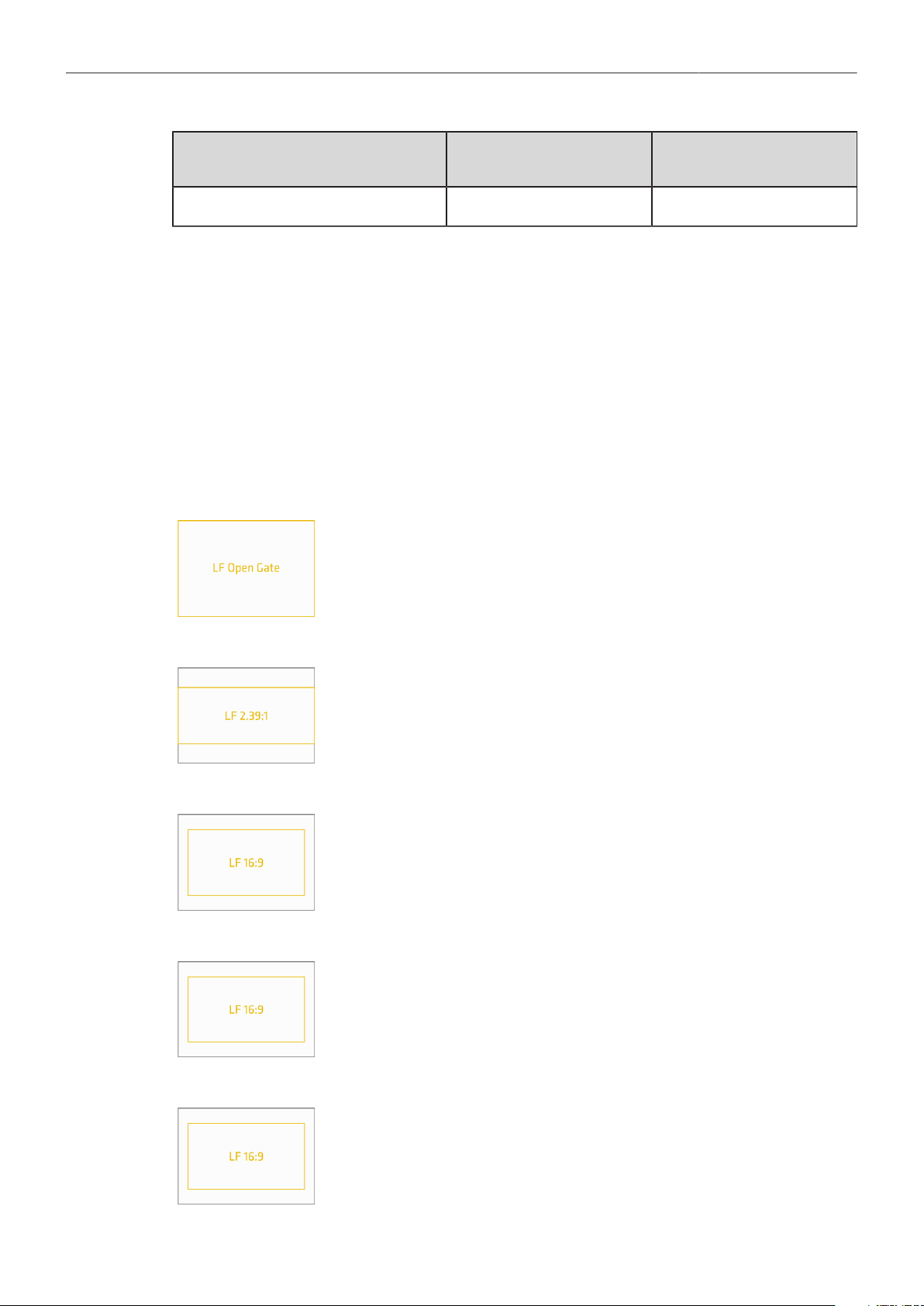
Recording 67
Recording Codec Color Coding Bit Rate (VBR, 24fps,
3840x2160)
MXF/ARRIRAW 12bit log 2389 Mbps
2. Select the desired recording codec.
Note: When the recording codec family is changed, the camera has to perform a partial software
reload. A popup window shows the settings that are affected by the reload and that may not be
available after the change. After confirming the popup window, the software is reloaded.
16.4 Recording Resolution
1. Select Menu > Recording > Recording Resolution.
Following options are available:
Recording
Resolution
Codec Sensor Active Image
Area (photosites)
Sensor Active Image
Area (dimensions)
Recording File Con-
tainer Size (pixel)
LF Open Gate 4.5K
ARRIRAW
Apple ProRes
4448 x 3096 36.70 x 25.54 mm
1.445 x 1.006"
4448 x 3096
4480 x 3096
LF 2.39:1
ARRIRAW
Apple ProRes
4448 x 1856 36.70 x 15.31 mm
1.445 x 0.603"
4448 x 1856
4480 x 1856
LF 16:9 UHD
ARRIRAW
Apple ProRes
3840 x 2160 31.68 x 17.82 mm
1.247 x 0.702"
3840 x 2160
3840 x 2160
LF 16:9 2K
Apple ProRes 3840 x 2160 31.68 x 17.82 mm
1.247 x 0.702"
2048 x 1152
LF 16:9 HD
Apple ProRes 3840 x 2160 31.68 x 17.82 mm
1.247 x 0.702"
1920 x 1080
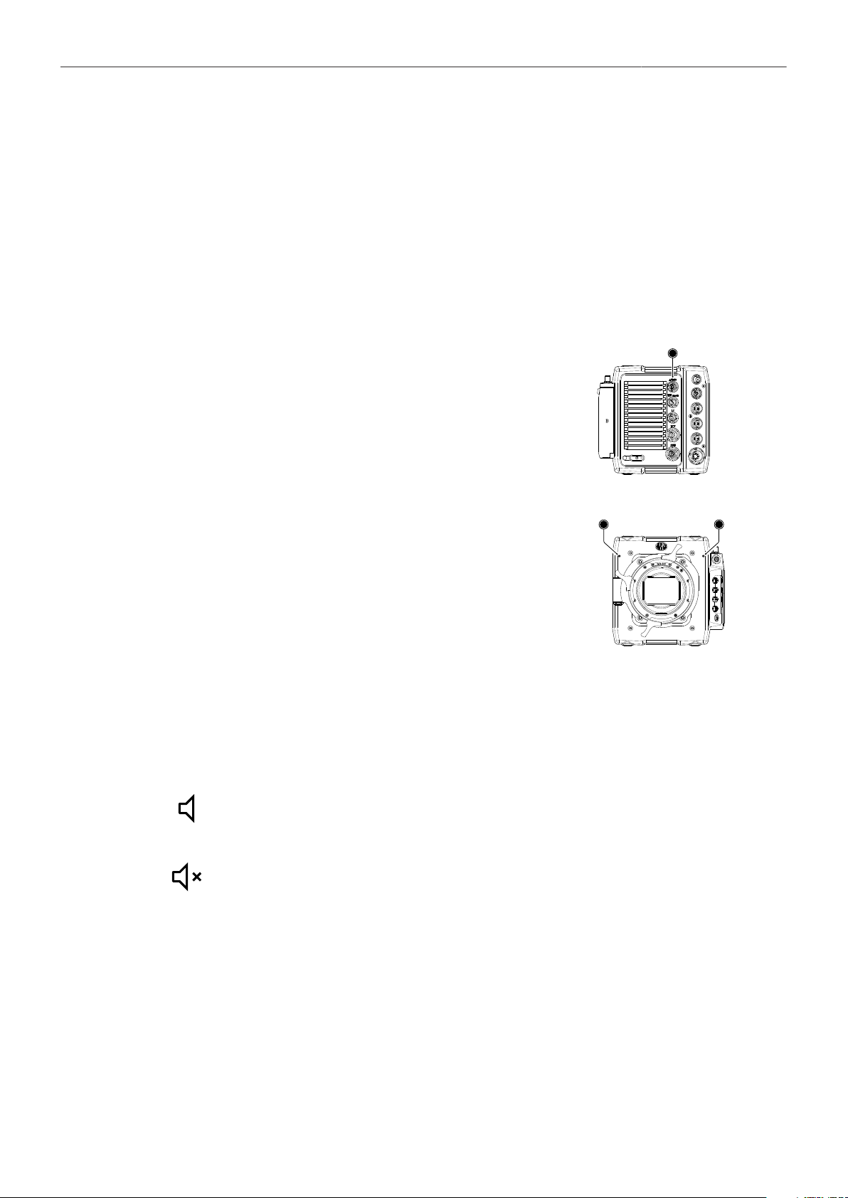
Recording 68
2. Select the desired recording resolution.
Note: Changing between recording resolutions may require a software reload. Confirm the reload
before it is performed. A popup window shows the settings that are affected by the reload and
which may not be available in the new mode. After confirming the popup, the software is reloaded.
16.5 Audio Recording
The camera can record 4 channel linear PCM (24 bit, 48 kHz) audio. With audio recording enabled, all
four audio channels are embedded in the SDI stream and output on the headphones out of the MVF-2.
Audio Inputs
The AUDIO connector (1) is located at the back of the cam-
era. It is a 2-channel +24dBu line level audio input with addi-
tional 12V power output to supply microphone preamplifiers.
Signals connected to the AUDIO connector are recorded to
audio channels 1 and 2.
1
The dual gain built-in microphones (2=right mic, 3=left mic)
are located at the camera front and can be used to record
a scratch audio track. The audio signal from these micro-
phones is recorded to audio channels 3 (left mic) and 4
(right mic) of the recorded clips. Per factory default, the
built-in microphones are disabled.
2
3
Audio Recording
► Select MENU > Recording > Audio Recording > Audio Recording to enable/disable audio recording.
Enabled audio recording is indicated through the audio icon displayed on home screen as well as
status info of the viewfinder and the SDI outputs:
Audio recording is enabled
Audio recording temporarily disabled, e.g. when the sensor frame rate does not match
the project frame rate.
If audio recording is switched off, no audio is recorded internally, HD-SDI contains no audio and the
headphones out on the MVF-2 is muted.
Channel 1/2 Control
1. Select MENU > Recording > Audio Recording > Channel 1.
Select MENU > Recording > Audio Recording > Channel 2.
Following options are available:
Manual Manual allows the user to manually apply gain to the input signal on the chan-
nel to reach a correct level.

Recording 69
Manual (+L) A limiter prevents the signal from clipping if the input signal level combined
with the set gain results in signal levels exceeding -6 dBFS.
Auto Auto matches a 4 dBu input signal to -20 dBFS. This setting leaves enough
headroom for recording and avoids audio clipping. When Auto is selected, au-
dio levels cannot be adjusted by the user.
2. Set channel 1 and 2 control to your preference.
Channel 1/2 Gain
1. Select MENU > Recording > Audio Recording > Ch 1 Gain
Select MENU > Recording > Audio Recording > Ch 2 Gain
2. Using the CLICKWHEEL, adjust the channel gain. The meters show the current level of the channel
signal in dBFS. Additionally audio levels are displayed on the HOME screen as well as the status
info of the viewfinder and the SDI outputs.
Note: Gain setting is only available when audio recording is enabled and channel control is set to either
Manual or Manual (+L).
Internal Microphones
The internal microphones can be used to record a reference track, sometimes also referred to as
"scratch track". Some software tools can synchronize the master audio to the image using the reference
track. The signal of the internal microphones is recorded to audio channels 3 and 4. The audio
recording level of the internal microphones is fixed, with the left microphone (channel 3) using a +18dB
higher gain than the right microphone in order to cover a wide range of audio levels.
► Select MENU > Recording > Audio Recording > Internal Microphones
to activate/deactivate recording of the internal microphones.
The microphone icon in the status info of EVF and the SDI outputs indicates active in-
ternal microphones.
Headphones Volume
1. Select MENU > Recording > Audio Recording > Headphone Volume.
2. Adjust the headphones' volume to your preference.
Test Tone
The camera can output a 1 kHz sine test tone on all recording channels, on headphones out and the
SDI outputs.
► Select MENU > Recording > Audio Recording > Test Tone.
Following options are available:
Off
-9 dBFS
-18 dBFS
-20 dBFS
Note: Test tone can only be activated when audio recording is enabled.

Recording 70
16.6 Rec Beeper and Tally Settings
1. Select MENU > Recording > Rec Beeper/Tally.
Following options are available:
Rec Start Beeper The camera gives an acoustic indication for start of recording.
Rec Stop Beeper The camera gives an acoustic indication for stop of recording.
Media Full Beeper The camera gives an acoustic indication for stopping recording due
to full card. For better distinction, a different sound pattern than the
start/stop beeper is used.
Tally MVF-2 Enables the tally light on the MVF-2.
16.7 File Naming Scheme
The ALEXA Mini LF automatically names files as they are created on the recording media. While it is
possible to change the file names later on a computer, it is not recommended, as the ALEXA naming
scheme has been developed to minimize the risk of duplicate file names.
A typical clip name would look like this: A004C010_190325_RN9O.mxf
The clip name consists of eight parts:
Camera Index (A) One character, A-Z. User assignable, should match the camera unit.
For example, the camera index A can be assigned to the A camera,
and B to the B camera etc.
Reel Counter (004) 3 characters, 001-999. Automatically assigned to each recording me-
dia, automatically advanced by one for each new media. The user can
change the counter for the next reel. This should only be done under
special circumstances, such as after changing the camera body in the
middle of a shoot.
Clip Index (C) One character, fixed to C. Main use is to separate the reel counter
from the clip counter.
Clip Counter (010) 3 characters, 001-999. Automatically advances each time a clip is
recorded.
Date (190325) Current date, in order YYMMDD, as set in Menu > System > System
time + date, separated from the other naming components by under-
scores.
Camera ID Prefix (R) One character, A-Z. Typical use would be setting one camera's ID pre-
fix to L (for left) and the other's to R (for right) for 3D applications.
Camera ID (N9O) The camera serial number encoded in 3 letters Base36 (0-9, A-Z).
N9O translates into decimal serial number 30156.
File name Extension (.mxf) All files are written as .mxf files.
The reel counter should be set to 001 at the beginning of a shoot. The camera will then automatically
advance the reel number each time a new recording medium is loaded into the camera, formatted and
recorded on. If a previously recorded medium is reloaded in the camera (comparable to a short end of a
film roll), it will keep its reel number and the camera will continue the reel count. If the medium is loaded
in another camera, it keeps its name, but a new folder with the according camera ID and reel number
is created in the root folder of the medium. It is possible, but usually not necessary, to manually change
the next reel number in the project menu.

Recording 71
16.8 Data Handling
Transferring recorded material from the original media should never be done using a simple file copy.
There are different software solutions available that will copy a file to one or several destinations and
perform a checksum calculation, comparing the material on the original media to the copies, to provide
a minimum effort safety check of data integrity. We strongly recommend using copy software and tools
with checksum calculation and verification. Checksum files should be calculated and generated as
sidecard files at the first copy process.
There are many types of checksums, all with the same purpose: safe and fast copy at the same time.
For example, the ‘MHL (Media Hash List)’. It’s an XML based file with a fixed structure, which always
contains the following information:
Creator Info
Name
Username
Hostname
Tool
Start date
Finishing date
hash
Path to file
File size in bytes
Last modification of the file
xxhash (calculated)
hash date
The ‘creator info’ is placed at the beginning of every ‘MHL’ checksum file. The rest of the ‘MHL’
file contains every single file incl. the xxhash value, which was calculated at the copy & checksum
generation process.
Changing a file or some values inside the ‘MHL’ checksum file results in an error during the checksum
verify process. Checksums should always be generated during the offload of the original camera
negative and should remain next to the files until the final backup process. We strongly recommend a
copy and checksum workflow from beginning (e.g. On-Set) to end (e.g. final LTO backup).
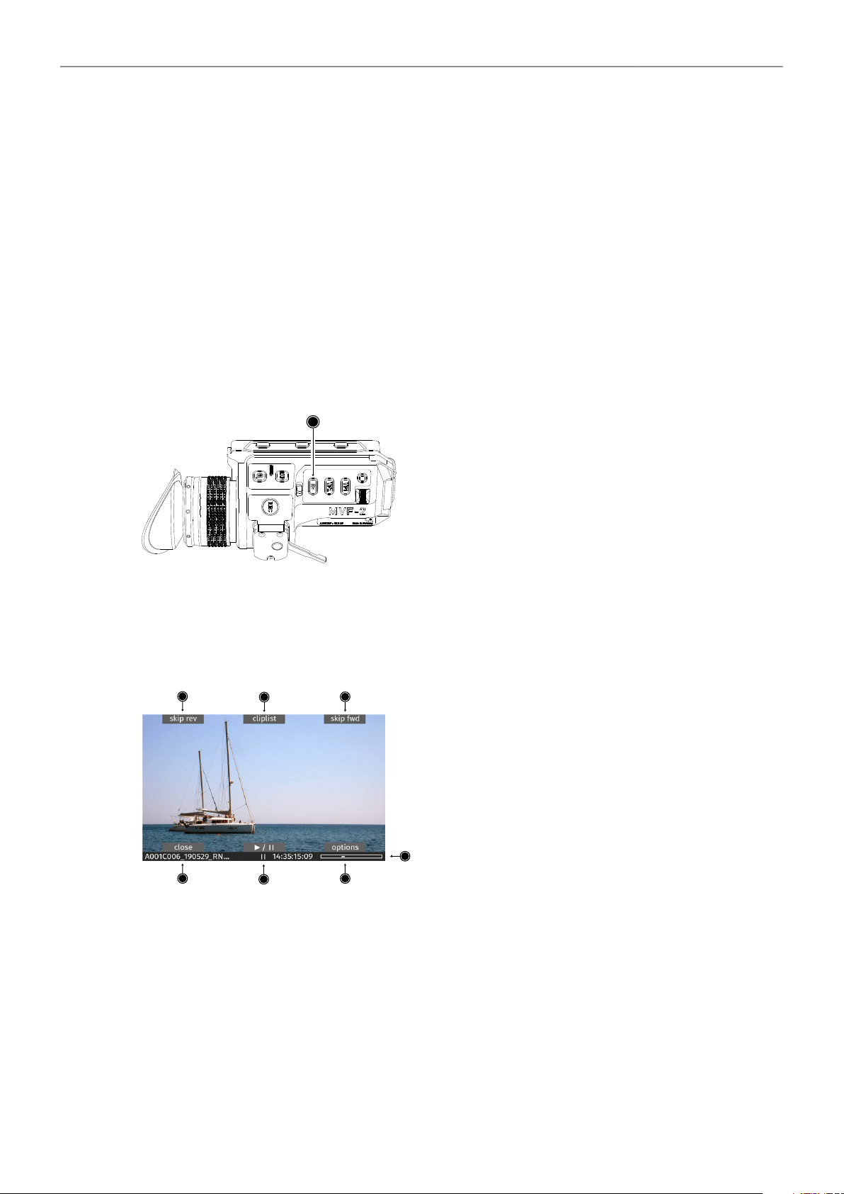
Playback 72
17 Playback
The camera offers various ways to start in-camera playback from the recording medium:
► Using the PLAY button on MVF-2
► Using user button 3 in combination with the Function Button FN
► Using a user button assigned with playback
► Using the Wireless Control Unit WCU-4
► Using the Web Remote (Beta Version)
► Using apps communicating with the camera through the Camera Access Protocol (CAP)
Starting Playback Using the PLAY Button on MVF-2
1
1. Press and hold the PLAY button (1) for one second
to start playback.
The camera goes into playback mode with the last
recorded clip paused at start.
2. You may toggle between play and pause by briefly
pressing the PLAY button again.
3. To exit playback press the PLAY button for one
second.
Playback Screen & Controls
When starting playback, the camera loads the last recorded clip (paused on the first frame). The
playback screen offers the following controls:
1
2
3
4
6
7
5
1
2
3
4
5
skip rev
cliplist
skp fwd
status bar
options
Loads the previous clip from the cliplist.
Select another clip for playback from a list of all clips on the recording medium.
Loads the next clip from the cliplist.
Shows clip name, timecode and playback progress bar of the selected clip.
Allows setting the clip end action.
6 play/pause Toggles between play and pause. Play/pause can also be toggled by pressing the PLAY button on the
MVF-2 or by pressing the JOGWHEEL. The JOGWHEEL can also be used to shuttle through a clip.
While playback is paused, use the JOGWHEEL to shuttle through the clip frame by frame. While play-
ing back, use the JOGWHEEL to increase or decrease the playback speed up to 512x forwards or
backwards.
7 close Exits playback.
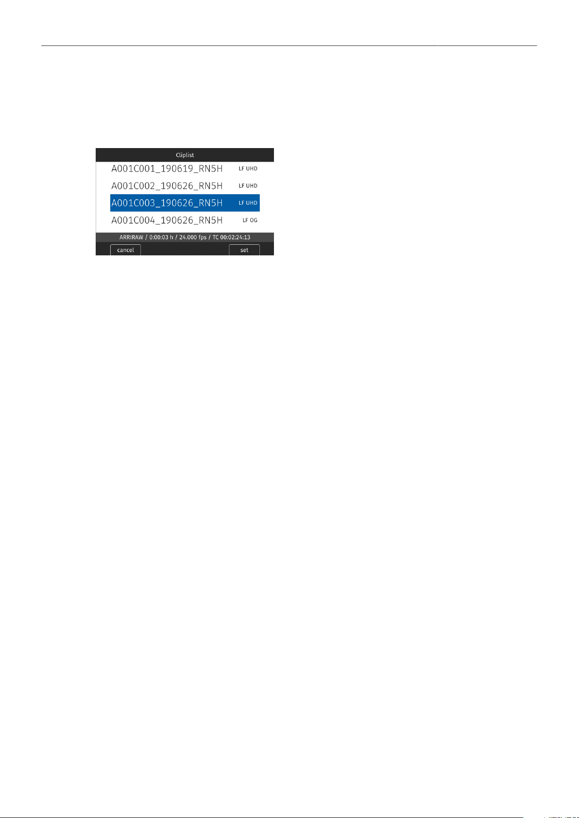
Playback 73
Cliplist
The cliplist lists all clip on the recording medium. For the selected clip, details like resolution, codec,
duration and timecode are displayed. When browsing through the cliplist, the first frame of the selected
clip is shown on EVF/Monitor and the SDI outputs.
1. Select PLAY > Cliplist.
2. Select a clip.
3. Press SET or the JOGWHEEL to load the clip for
playback.
4. Press CLOSE to leave the cliplist.
Note: Clips may be grayed out if they can not be played back because their recording resolution is not
compatible with the currently set recording resolution.
Playback Options
1. Select PLAY > Options.
The Play End Mode defines the behavior when playback reaches the end of a clip and offers the
following options:
Pause on end
Pause on start
Loop
Play next clip
Exit playback
Playback pauses at the end of the clip.
Playback pauses at the beginning of the clip.
Playback continues from the beginning of the same clip again.
Playback continues with the next clip in the cliplist.
Camera exits playback.
2. Set the desired play end mode.
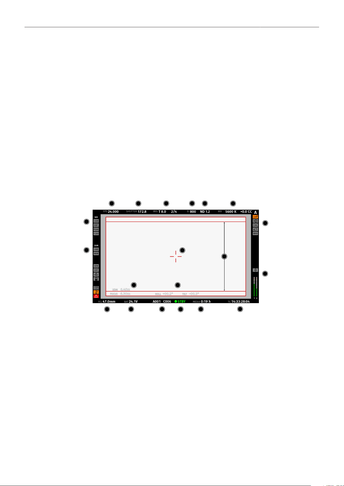
Monitoring 74
18 Monitoring
The monitoring submenu covers all settings related to EVF, Monitor and SDI as well as frame lines and
other overlays on these outputs.
18.1 Status Information and Status Overlays
EVF and SDI Status Information
The camera displays camera status information on the MVF-2 and the SDI outputs. At the top and
bottom of the screen, the camera displays textual status information. The top status bar consists
of sensor FPS, shutter angle, exposure index, ND filter and white balance. The bottom status bar
displays information about the battery level, reel and clip, camera status, remaining recording time and
timecode.
On the left and right of the screen, icons provide information about the current status of the camera.
The icons are organized into groups. The left icon groups display the EVF/SDI configuration as well
as the camera configuration. Additionally various other icons are displayed below to indicate certain
active parameters. The right side shows the audio meters as well as other icons (described below).
Furthermore the user can activate the display of additional camera information such as lens data and
electronic horizon.
1
2
3
4
5
6
7
8
9
10
11
12
13
14
15
16
17
18
19
20
Top Section
1 FPS Shows the current sensor frame rate. The FPS label turns orange if the sensor frame rate does not
match the project rate.
2
3
4
5
6
SHUTTER
IRIS
EI
ND
WB
Shows the current shutter value (here: shutter angle).
Shows the current lens IRIS, including sub stops.
Shows the current exposure index.
Shows the current setting for the ND filter.
Shows the current white balance value.
Bottom Section
7
8
FCL
BAT
Shows the current focal length of the lens (if lens data is available).
Shows the current battery supply level. If the level is below the configured warning level, the value is
flashing orange.
9 CLIP Shows the current reel and clip number.

Monitoring 75
10 STATE Shows the main camera status:
STBY
REC
PLAY
ERASE
FULL
None
ERROR
Ready for recording
Recording
Playback
Medium erase in progress
Recording medium full
No media inserted
Camera error. See MENU > Alerts for more information
11 MEDIA Shows the remaining capacity of the recording medium at current FPS and codec combination in real
time. When medium capacity is less than two minutes, capacity values starts flashing orange.
12 TC Shows the current timecode. The TC label turns orange if the sensor frame rate does not match the
project rate.
Left Section
13 EVF / SDI
Status
Look
EXP
PEAK
AD
Shows the current EVF/SDI processing (Look, Log C or ALEXA Classic 709).
Indicates that the exposure tool is active on the respective output.
Indicates that peaking is active on the respective output.
Indicates that anamorphic desqueeze is active and which lens squeeze factor is selected.
14 Camera
Status
UHD
RAW
GEN
EXT
FAN
LOCK
GRAB
TEMP
ALERT
Shows the current recording resolution.
Shows the current recording processing (RAW or Log C).
Indicates that Genlock is activated. If orange: Genlock signal is missing or not usable.
Indicates that EXT sync mode is activated.
Shows that the camera needs to increase the fan speed to cool the camera properly.
Indicates that the camera controls are locked.
Frame Grab is active.
Indicates that the camera temperature is outside of its optimal range.
Indicates an active alert state.
Right Section
15 Camera Index
Letter
Shows the camera index letter.
LDS
USB
CAL
WiFi
WRS
Shows that the LDS interface has been disabled manually.
Shows a connected USB medium.
Lens motor calibration is in progress. If orange: lens motor calibration is required.
WiFi is active.
White Radio is active.
16 MIC
Audio Meters
Internal microphones are active.
Shows the current level of camera audio channel signals. If audio recording is currently not possible, an
orange speaker icon with a small x is shown. Black markers at signal levels -20, -18, -9 dBFS for refer-
ence test tone. Yellow marker at -5 dBFS and red marker at -2 dBFS indicate a signal close to clipping.
A red frame around the meter indicates a clipping at the A/D stage.
Other
17 Center Cross Marks the center of the image to help in framing.
18 Frame Line Frame line (here: ARRI 1:1.85)
19 UDM
Focus
Shows measurements from Ultra Distance Measures.
Shows the current focus distance of the lens (if lens data is available).
20 HOR Shows the electronic horizon or numeric roll and tilt values.

Monitoring 76
Configuration of Overlays
1. Select MENU > Monitoring > EVF/Monitor > EVF Overlays.
Select MENU > Monitoring > EVF/Monitor > Monitor Overlays.
Select MENU > Monitoring > SDI > SDI Processing > SDI Overlays.
Following settings are available:
Frame Lines Sets frame lines on or off. Used as a framing reference tool with
typically an image frame, a center mark and aspect ratio. For infor-
mation on setting frame lines, see "Setting frame lines".
Frame Line Shading Applies an outside shading to the area between the frame line and
the remaining active image area.
Center Mark Sets the center mark between Off, Dot, Small Dot, Cross or Small
Cross.
Surround Mask Select to adjust the surround mask settings. If surround view is set
to On, it must be separated from the recorded image area to allow
proper framing, either as black line, colored line, or semi transpar-
ent with 25, 50, 75 or 100% percent opacity (opacity selection is not
available for the MVF-2 flip-out monitor).
Status Info Only for EVF and SDI. Sets camera status overlays between Off,
Overlay (status on the active image), or Safe (status outside the ac-
tive image).
Configuration of Status Info Components
1. Select MENU > Monitoring > EVF/Monitor > EVF Overlays > Status Components.
Select MENU > Monitoring > SDI > SDI Processing > Overlays > Status Components.
2. Following settings are available:
Info 1 Enables/disables the top and bottom section of the status info.
Info 2 Enables/disables the left and right section of the status info.
Timecode Enables/disables display of the timecode on the bottom right of the
image.
Audio Enables/disables display of the audio levels located on the lower
right side of the image.
Lens Data Enables/disables iris and focal length readings.
Lens Focus Distance Sub-option of lens data setting. Enables/disables display of focus
distance readings (19), located on the lower left corner of the im-
age.
UDM Sub-option of lens focus distance setting. Enables/disables display
of distance readings from the Ultrasonic Distance Measure UDM-1
(in combination with LCUBE CUB-1). Located above the lens focus
distance overlay.
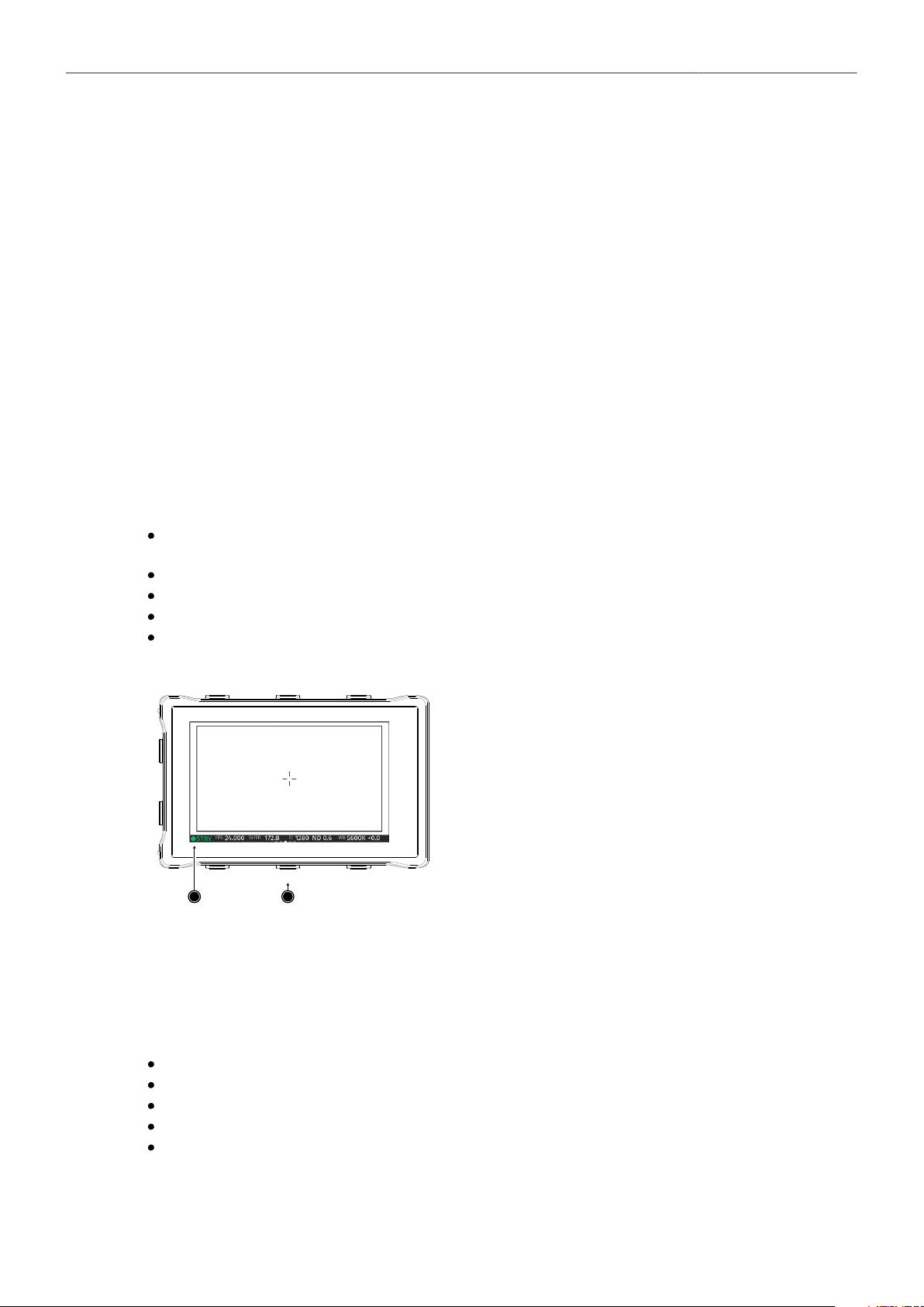
Monitoring 77
Camera Index Letter Displays the camera index letter in the top right corner of the image.
Helps to identify camera image output when shooting with multiple
cameras. Note: Only available for SDI.
Electronic Horizon Displays an horizon overlay representing the roll and tilt of the cam-
era measured by the camera's position sensor. This sensor can be
reset, if it appears to have an offset. For information on resetting
the camera's position sensor, see "Reset of Electronic Horizon",
page 101.
Show Numeric Values Sub-option of electronic horizon. Shows the tilt and roll of the cam-
era in degrees as measured by the camera's position sensor (20).
3. Configure the status info components to your preference.
18.1.1 Flip-out Monitor Status Bar
The flip-out monitor of the MFV-2 shows slightly different overlays than the EVF and the SDI outputs.
When set to display the camera live image, a status bar is displayed below the image. The monitor
status bar offers the display of five groups:
Main camera parameters: FPS, shutter, exposure index, ND filter and white balance (as shown
below)
Audio meters and timecode
Status icons
Lens data: Focus distance, iris and focal length
Recording: media remaining capacity, clip duration, codec and battery level
1
2
Use the lower screen buttons (2) to change the status
bar (1) content. The lower center screen button returns
to the main camera parameters.
18.1.2 Overlay Menu
The overlay menu offers quick access to the main camera parameters.
When activated, it is visible in the top section of the image on the MVF monitor and EVF and on any
SDI output which has SDI processing activated. The overlay menu is a quick way to change the
following camera settings:
Sensor FPS
Shutter (Shutter Angle / Exposure Time)
Exposure Index
ND filter
White Balance
Sensor FPS, Shutter and White Balance cannot be changed manually, but in the range of their user
predefined lists. ND filter is changed instantly and requires no additional confirmation step.
A white frame marks the selected parameter. A white block indicates active edit mode.
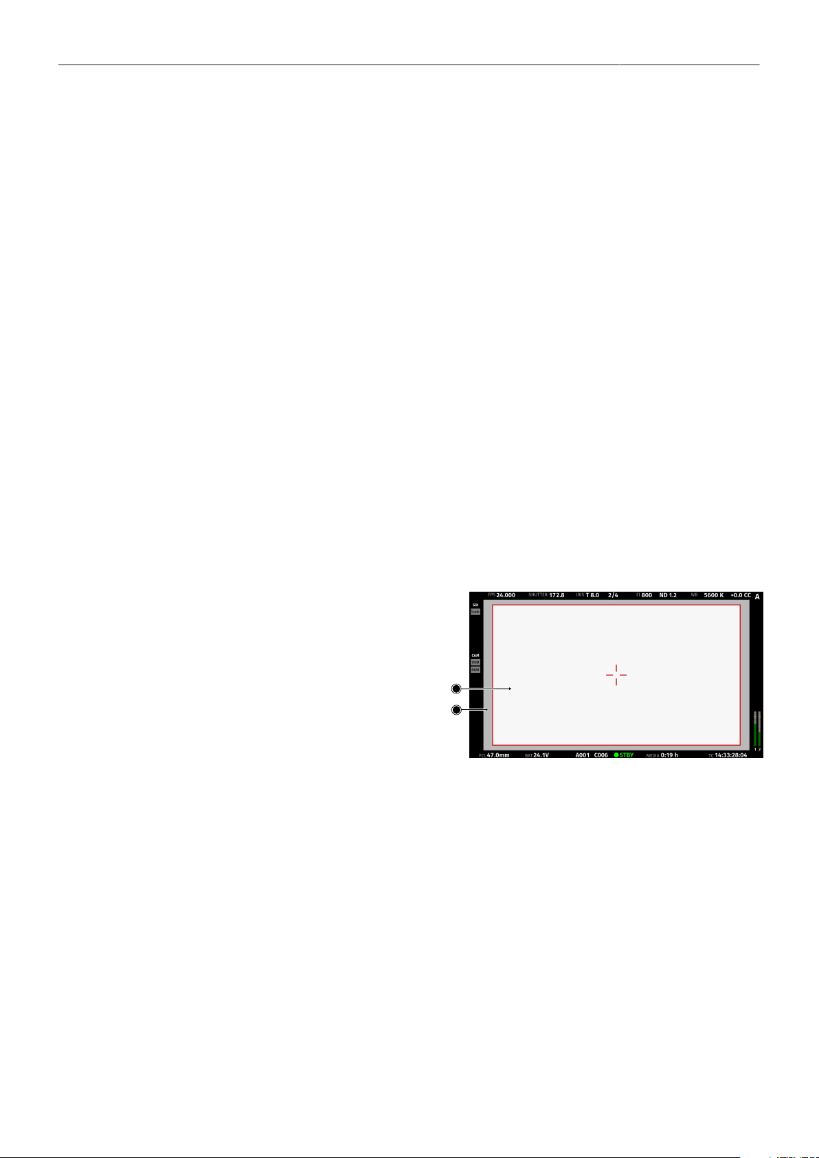
Monitoring 78
Activation and Control Using the Camera Buttons
1. Activate the overlay menu by pressing FN + 1.
2. Select a parameter with buttons 1 or 2.
3. Start editing the parameter by pressing button 3.
4. Select the new parameter value with buttons 1 or 2.
5. Confirm the new value by pressing button 3.
6. If required, repeat steps 2-5 for other parameters.
7. Exit the overlay menu by pressing FN + 1.
Activation and Control Using a User Button
1. Assign a user button to "Overlay Menu".
2. Activate the overlay menu by pressing the user button.
3. Select a parameter with the JOGWHEEL of the MVF-2.
4. Start editing the parameter by pressing the JOGWHEEL.
5. Change the value of the parameter with the JOGWHEEL.
6. Confirm the new value by pressing the JOGWHEEL.
7. If required, repeat steps 3-6 for other parameters.
8. Exit the overlay menu by pressing the user button.
18.2 Surround View
Surround View displays additional pixels out-
side the recorded image area (1), allowing
the operator to see outside the recorded im-
age and keep unwanted objects, such as mi-
crophone booms, out of the shot. The sur-
round view area (2) can be separated from the
recorded image area by setting the surround
mask (here: 50% opacity mask). To view on-
ly the recorded image, set surround view to
off. Note: Surround View is not available for
recording resolution LF Open Gate 4.5K.
1
2
1. Select MENU > Monitoring > EVF/Monitor > Surround View.
Select MENU > Monitoring > SDI > SDI processing > Surround View.
2. Set surround view on or off. Per factory default surround view is enabled.
Surround Mask
The surround mask setting helps to visually separate the surround view from the recorded image area.
1. Select MENU > Monitoring > EVF/Monitor > EVF Overlays > Surround Mask
Select MENU > Monitoring > EVF/Monitor > Monitor Overlays > Surround Mask.
Select MENU > Monitoring > SDI > SDI Processing > SDI Overlays > Surround Mask.
Following options are available:
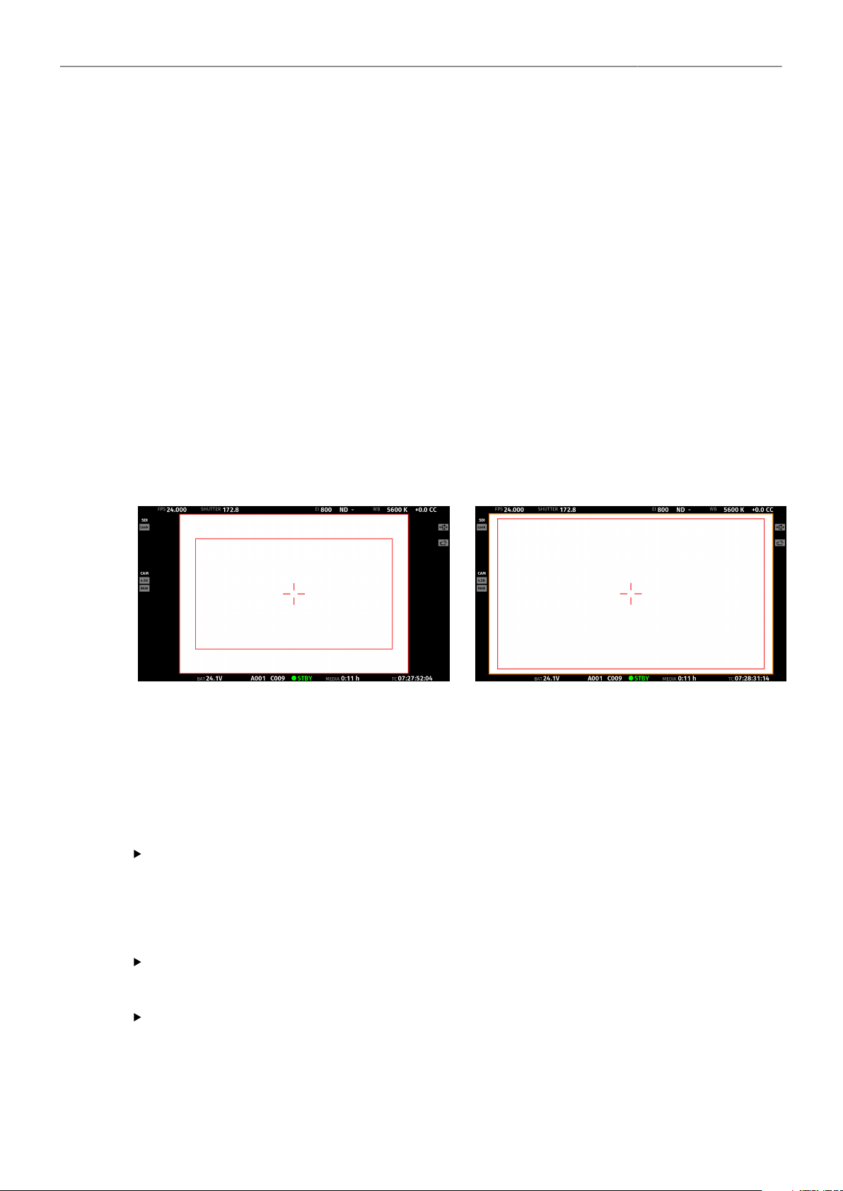
Monitoring 79
Black Line
Colored Line
Mask 25%
Mask 50%
Mask 75%
Mask 100%
Surround mask is separated with a black line.
Surround mask uses the same color as frame lines.
Surround mask is displayed with 25% opacity.
Surround mask is displayed with 50% opacity.
Surround mask is displayed with 75% opacity.
Surround mask is displayed with 100% opacity.
2. Set the preferred surround mask.
18.3 Magnification
When shooting with frame lines or aspect ratios that only use a cropped area of a recording resolution
the actual image content defined by the frame line might not be displayed large enough.
The magnification setting gives the user access to variably scaling of the monitoring outputs and sets
a persistent image magnification, so the area defined by the frame line can be displayed as large as
desired.
Magnification can be adjusted in steps of 1% from 100% to 200% for the EVF and the SDI outputs,
individually or globally. If less than the recorded area is shown an orange border will be shown at the
frame boundaries where the recorded image exceeds what is displayed.
Two screen shots from an ALEXA Mini LF in recording resolution LF Open Gate 4.5K with a 1.78 UHD frame line (red rectan-
gle) applied. The left screen shot shows the SDI output without magnification applied. The right screen shot shows the SDI out-
put with magnification applied to enlarge the image (in this example set to 135%). An orange border indicates that the recorded
area exceeds the displayed image.
Setting the Magnification
The camera menu offers the following settings to adjust magnification:
Select MENU > Monitoring > Master Magnification
to set the magnification of the EVF and the SDI outputs simultaneously.
Note: When individual outputs have been set to different magnification values, the master
magnification menu entry shows "-". Changing the master magnification will force the magnification
of all outputs to the new value.
Select MENU > Monitoring > EVF/Monitor > Magnification
to set the magnification of the EVF and the flip-out monitor.
Select MENU > Monitoring > SDI > SDI Processing > Magnification
to set the magnification of the SDI outputs.
Note: Magnification can only be applied with SDI image set to processed.
Note: Magnification is reset to 100% when the recording resolution is changed.

Monitoring 80
18.4 Frame Lines
To aid in framing, both the MVF-2 and the SDI outs can display frame lines overlaid on the image.
Frame lines can be considered electronic versions of ground glass markings in film cameras.
You can configure which frame line the camera should show and how it should be displayed (color and
transparency). You can also configure up to two user rectangles which allow you to mark a rectangular
area on the image, e.g. for marking an area that you need to keep clear during shooting for later VFX
insertion.
Custom frame lines can be created using the Frame Line & Lens Illumination Tool.
Setting the Frame Line
1. Select MENU > Monitoring > Frame Lines > Frame Line.
A list of installed frame lines is displayed.
2. Select a frame line from the list or add and select a custom frame line.
Frame Line Color
The frame line color is a global setting and defines the color of the frame line, the center mark, the user
rectangle(s) and the surround mask (if mask is set to Colored Line).
1. Select MENU > Monitoring > Frame Lines > Frame Line Color .
Following frame line colors are available:
Red
Green
Blue
Cyan
Magenta
Yellow
Black
White
2. Set the desired frame line color.
Frame Line Intensity
You can set the brightness of the frame line, center cross and user rectangles.
1. Select MENU > Monitoring > Frame Lines > Frame Line Intensity
2. Set the frame line intensity in a range from 1 to 4.
User Rectangles
You can configure width, height and offset (i.e. position from left and top screen edge) in per mill. You
can also reset all settings.
1. Select MENU > Monitoring > Frame Lines > User Rectangles.
You have the following options:
Off
Rect 1
Rect 2
Rect 1 + 2
User Rectangles are not displayed.
Only user rectangle 1 is displayed.
Only user rectangle 2 is displayed.
User rectangels 1 + 2 are displayed.
2. Configure the display of user rectangles.
3. Select MENU > Monitoring > Frame Lines > User Rectangle 1 or MENU > Monitoring > Frame
Lines > User Rectangle 2.
You have the following options:

Monitoring 81
Width
Height
Offset Left
Offset Top
Reset All
Adjusts the user rectangle width in the range of 0-999.
Adjusts the user rectangle height in the range of 0-999.
Adjusts the horizontal user rectangle offset in the range of 0-1000.
Adjusts the vertical user rectangle offset in the range of 0-1000.
Resets all values.
4. Configure the user rectangle according to your needs.
5. To reset the configuration, press Reset all.
Frame Lines Saved in Metadata
The camera records up to six rectangular frame lines from the active frame line files into metadata. This
metadata is present in all recording formats and on all HD-SDI outputs. The frame line metadata can be
used either for automatic dailies creation or for displaying the frame lines in post.
Automated Dailies Creation
It is possible to load two frame line files simultaneously into the camera for a total of six frame lines
displayed in the viewfinder or on MON OUT. In metadata, the frame lines of the first file will be called
frame line 1A, frame line 1B and frame line 1C, while the frame lines of the second file will be called
frame line 2A, frame line 2B and frame line 2C. Frame line 1A is automatically the master frame line.
The master frame line can be used by dailies creation software to automatically frame the dailies. This
feature is expected first on the Codex Vault, but other dailies creation software is expected to follow
suite.
Frame Lines in Post
The frame line metadata makes the original camera frame lines available during post production for
editing, color grading or compositing tools and can be displayed as an overlay in the respective image
viewer.
NOTICE
Frame lines created for a sensor mode other than the currently active are not selectable.
18.5 Anamorphic Desqueeze
Setting the Lens Squeeze Factor
The lens squeeze factor determines the factor that is used for anamorphic desqueeze on EVF/Monitor
and SDI. This value is also written into the metadata of the clip and allows video players and editing
software to automatically desqueeze clips that have been shot with anamorphic lenses.
► Select MENU > Recording > Project Settings > Lens Squeeze Factor and select the appropriate
factor.
Anamorphic desqueeze is automatically activated on EVF/Monitor and the SDI outputs.
Activation of Anamorphic Desqueeze for EVF/Monitor and SDI
With the desqueeze factor defined in the project settings, anamorphic desqueeze can be then enabled
and disabled for EVF/Monitor and SDI so that the image is displayed with the correct aspect ratio.
1. You have the following options:
Select MENU > Monitoring > EVF/Monitor > Anamorphic Desqueeze.
Select MENU > Monitoring > SDI > Anamorphic Desqueeze.
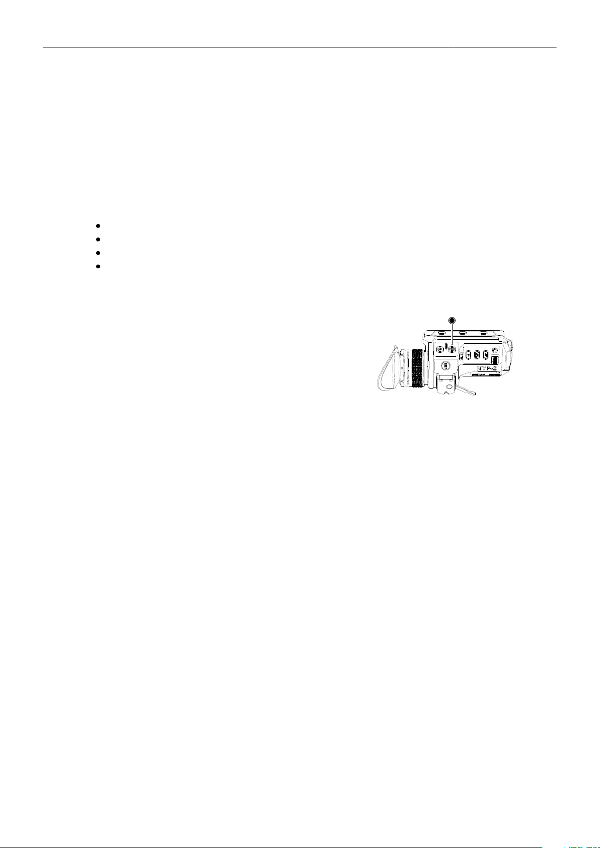
Monitoring 82
2. Enable or disable anamorphic desqueeze for the EVF/Monitor and/or SDI outputs.
3. Additionally you can assign "EVF/Mon. Desqueeze" and "SDI Desqueeze" to user buttons to quickly
enable and disable anamorphic desqueeze for the corresponding path. For further information on
how to assign functions to user buttons please see "User Buttons", page 107.
18.6 Exposure Tools
The camera offers two exposure tools for evaluation of the image exposure levels, False Color and
Zebra. You can select which exposure tool you want to use to evaluate the image exposure. The
exposure tool can be activated through
the EXP button on the MVF-2 (for EVF and Monitor)
a user button assigned with EVF/Mon. Exp. Tool (for EVF and Monitor)
a user button assigned with SDI Exp. Tool (for the SDI Outputs)
the EVF/Mon. and SDI exposure tool entries in the camera menu
Activation of Exposure Tool with MVF-2
► To activate the exposure tool on both EVF and
Monitor, press the EXP button (1) on the MVF-2.
Press the EXP button again to deactivate the expo-
sure tool.
1
Activation of Exposure Tool with User Buttons
1. Assign a user button with EVF/Mon. Exp. Tool
to be used for activation of the exposure tool on EVF and Monitor.
2. Assign a user button with SDI Exp. Tool
to be used for activation of the exposure tool on the SDI outputs.
3. Press the user button to toggle the exposure tool on/off.
For more information on user buttons please see "User Buttons", page 107.
Activation of Exposure Tool in Camera Menu
1. Select MENU > Monitoring > EVF / Mon. > Exposure Tool
to activate the exposure tool on EVF and Monitor.
2. Select MENU > Monitoring > SDI > SDI Processing > Exposure Tool
to activate the exposure tool on the SDI outputs.
18.6.1 False Color
The false color display is a tool to check for correct exposure. It can be activated on EVF/Monitor and/
or the SDI outputs, and takes the respective gamma setting as a basis for calculation. When active,
the image is turned into a gray scale image with important luminance ranges shown in signal colors.
Note that the false color tool is only suitable for checking exposure and is not an appropriate tool for
checking other image parameters or sensor quality. Activating false color replaces luminances with the
following colors:

Monitoring 83
White Clipping
Just below white clipping
One stop over medium gray (Caucasian skin)
18% medium gray
Just above black clipping
Black clipping
100% - 99%
99% - 97%
56% - 52%
42% - 38%
4.0% - 2.5%
2.5% - 0.0%
Red
Yellow
Pink
Green
Blue
Purple
Signal Level
Color
Exposure
False Color Configuration
► Select MENU > Monitoring > Exposure Tools > Select EVF/Mon. Exp. Tool
and select False Color to use False Color as exposure tool for EVF and Monitor.
► Select MENU > Monitoring > Exposure Tools > Select SDI Exp. Tool
and select False Color to use False Color as exposure tool for the SDI outputs.
False Color Mode
The result of activating false color can be varied to either Monitoring-based or Log C-based. This
choice is global and will be valid for all viewing outputs.
Monitoring-based When choosing Monitoring-based false color and false color is activated (with the
EXP button on the viewfinder, for example), false color is calculated based on
the video signal of the respective monitoring output. In other words, whatever is
seen on the image path is the basis for calculating false color.
If you have a monitor output or the viewfinder configured to show Log C, false
color levels will be calculated based on the Log C signal.
If you have a monitor output or the viewfinder configured to LOOK or ALEXA
Classic 709, false color levels will be calculated based on the image with the look
applied or the ALEXA Classic 709 image respectively.
Log C-based When choosing Log C-based false color, false color is always calculated based
on the Log C image. When false color is activated (with the EXP button on the
viewfinder, for example), the respective monitoring output is switched to Log C
processing, false color levels are calculated based on the Log C signal and false
color is activated. When de-activating false color, the image path is switched
back to its previous processing and false color is switched off. This setting
makes most sense for projects that record Log C images. While your monitoring
image paths can be set to show Rec 709 or a look to provide a preview for all,
you will want to know the exposure levels of the signal you are actually recording
(Log C) when checking false color. Log C-based false color mode is mandatory
when using HDR ALF-2 files.
NOTICE
When a HDR ALF-2 look file is loaded and activated in the camera, false color mode automatically
switches to 'Log C-based'. This is because HDR look files do not generate video signals over 75%,
which means that overexposure might not be indicated correctly in ‘Monitoring-based false color’
mode.
When you are using a look file that does not utilize the full signal level range and you activate false
color on a monitoring path where Look processing is active, false color will not indicate over- or
underexposure. This specifically applies to Rec 2100 PQ Look files, as they level out at a maximum
signal level of 75%.
When using look files with extreme color grading, it is possible for 'Monitoring-based' false color to
show an inaccurate result.

Monitoring 84
18.6.2 Zebra
In Zebra mode, the camera overlays up to two luminance ranges with diagonal stripes. High zebra
ranges above, Mid zebra around the user defined luminance value.
Zebra Configuration
► Select MENU > Monitoring > Exposure Tools > Select EVF/Mon. Exp. Tool
and select Zebra to use Zebra as exposure tool for EVF and Monitor.
► Select MENU > Monitoring > Exposure Tools > Select SDI Exp. Tool
and select Zebra to use Zebra as exposure tool for the SDI outputs.
Zebra Setup
1. Select MENU > Monitoring > Exposure Tools > Zebra Setup.
Following settings are available:
Zebra Mode
High Zebra Level
High Zebra Color
Mid Zebra Range
Mid Zebra Color
Sets the zebra mode to High, Mid, or both.
Sets the exposure level (in %) above which high zebra is active.
Sets high zebra pattern color.
Sets the active range (in %) around a mid zebra level.
Sets the mid zebra pattern color.
2. Adjust the Zebra settings to your preference.
Note: Zebra is not available on image paths with processing set to Log C. Please use False Color to
check the image exposure on image paths with processing set to Log C.
18.7 Focus Tools
18.7.1 Peaking
Peaking highlights in-focus image areas for better focus judgment. Peaking can be activated through
the camera menu or a user button.
Peaking Configuration
1. Select MENU > Monitoring > EVF/Monitor > EVF/Monitor Processing > Peaking
to configure Peaking for EVF and Monitor.
2. Select MENU > Monitoring > SDI > SDI Processing > Peaking
to configure Peaking for the SDI outputs.
3. The following options are available:
Peaking Activates Peaking for the corresponding output.
Peaking Mode Select between Color and Aperture. Select color peaking to overlay in-
focus areas with a color, and select aperture peaking to enhance object
edges only.
Peaking Level Sets a peaking strength in range from 1 (minimum) to 20 (maximum).
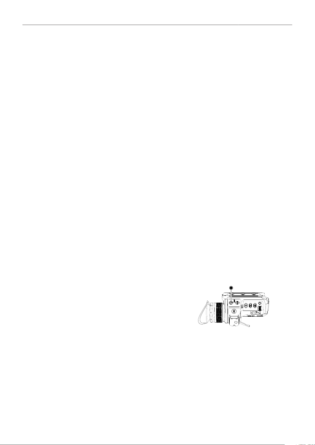
Monitoring 85
Peaking Offset Shift Adjusts the threshold for Color Peaking to become active, relative to the
peaking level. Note: A negative offset shift, in particular with high ASA
ratings, can increase the peaking results.
Color Select the color for Color Peaking.
Activation of Peaking with User Buttons
1. Assign a user button with EVF/Mon. Peaking
to be used for activation of Peaking on EVF and Monitor.
2. Assign a user button with SDI Peaking
to be used for activation of Peaking on the SDI outputs.
3. Press the user button to toggle Peaking on/off
For more information on user buttons please see "User Buttons", page 107.
Activation of Peaking in Camera Menu
1. Select MENU > Monitoring > EVF / Mon. > Peaking
to activate the exposure tool on EVF and Monitor.
2. Select MENU > Monitoring > SDI > SDI Processing > Peaking
to activate the exposure tool on the SDI outputs.
18.7.2 Zoom
The camera supports to zoom into the image e.g. to better judge focus. The camera offers five zoom
positions: center, top left, top center, top right, bottom right, bottom left. While Zoom is activated, the
zoom position can be changed by using the JOGWHEEL or the soft buttons on the MVF-2, if the
monitor is flipped out and set to display the live image. Active Zoom is indicated by an orange frame
around the image. Frame lines are deactivated while Zoom is active.
Note: Anamorphic Desqueeze is temporarily disabled while Zoom is active.
Zoom on EVF/Monitor
The MVF-2 has a dedicated ZOOM button (1).
1. Press the ZOOM button to activate/deactivate
Zoom on EVF and Monitor.
2. To change the Zoom position, rotate either the
JOGWHEEL or the USER WHEEL.
Note: Changing the zoom position using the JOG-
WHEEL or USER WHEEL is not supported when
the monitor is set to display the HOME screen or
the camera menu.
1
Zoom on SDI
Zoom on the SDI outputs can only be activated through a user button. The camera offers three SDI
Zoom related user button functions:
1. Assign a user button with SDI Zoom.
The SDI Zoom user button activates/deactivates Zoom on the SDI outputs.
2. Assign a user button with SDI Zoom Position.
The SDI Zoom Position user button changes the Zoom position while SDI Zoom is activated.

Monitoring 86
3. Assign a user button with SDI Zoom (Smart).
The SDI Zoom (Smart) user button activates Zoom on the first button press, further button presses
change the zoom position and a button long press deactivates Zoom.
18.8 SDI Configuration
SDI Format
Both SDI BNC connectors output SDI signals in 1920 x 1080 (422 1.5G, 422 3G, 444 3G) 3840 x 2160
(422 6G) according to SMPTE standards 292M, ST 424:2012 and ST 2081.
1. Select MENU > Monitoring > SDI > SDI 1 Format or
2. Select MENU > Monitoring > SDI > SDI 2 Format.
The following SDI formats are available:
Format Resolution Sampling Fps SMPTE Standard
422 1.5G HD 1920 x 1080 4:2:2 YCbCr 23.976 p/psf
24 p/psf
25 p/psf
29.97 p/psf
30 p/psf
422 3G HD 1920 x 1080 4:2:2 YCbCr 48 p**
50 p
59.94 p
60 p
SMPTE ST 292
444 3G HD 1920 x 1080 4:4:4 RGB 23.976 p
24 p
25 p
29.97 p
30 p
422 6G UHD* 3840 x 2160 4:2:2 YCbCr 23.976 p
24 p
25 p
29.97 p
30 p
3. Set the desired SDI format.
* not available for LF 16:9 HD and LF 16:9 2K mode.
**48p may not be supported by some SDI devices, as this is not a defined frame rate according to the
SMPTE standard.
SDI Processing
You can configure the SDI processing elements.
► Select MENU > Monitoring > SDI > SDI Processing.
Following options are available:

Monitoring 87
Surround View
Magnification
Exposure Tool
Peaking
Overlays
Activates or deactivates surround view.
Apply magnification to the SDI outputs.
Activates or deactivates the exposure tool.
Configures peaking for SDI.
Configures the SDI overlays.
SDI Frame Rate
You can set the frame rate together with the scan format on the SDI output. If the frame rate is lower
than the sensor fps, frame drops will occur. If it is higher, duplicate frames will be output. The available
frame rates depend on the selected SDI format.
► Select MENU > Monitoring > SDI > SDI 1 Frame Rate or
► Select MENU > Monitoring > SDI > SDI 2 Frame Rate and select the desired frame rate.
Available scan formats are:
p (progressive) Transmits images line by line starting at the top left
pixel.
psf (progessive segmented frame) Splits progressive images into fields (odd lines
and even lines). Transmits these (all odd before all
even) line by line.
SDI 3G Level
For the single link 3G SDI formats, you can choose whether to use 3G level A or B. Refer to the manual
of your connected devices to decide which 3G level to choose.
► Select MENU > Monitoring > SDI > SDI 1 3G Level or
► Select MENU > Monitoring > SDI > SDI 2 3G Level and select the desired 3G level.
SDI Image
The SDI image setting determines how images are output over SDI:
► Select MENU > Monitoring > SDI > SDI 1 Image or
► Select MENU > Monitoring > SDI > SDI 2 Image.
Following options are available:
Clean Images are identical to the images that the camera records internally. They do
not contain any overlays and do not show any surround view.
Processed Images may contain overlays and show surround view.
SDI 1 and 2 cannot be configured completely independently from each other in reference to the image
setting. The SDI 1 setting determines the available options for SDI 2. The following combinations are
possible:
SDI 1 SDI 2
clean clean
clean processed
processed clean

Monitoring 88
If both SDI 1 and 2 are supposed to show processed images, SDI 2 needs to be configured as SDI 1
clone.
SDI 2 Clone
You can set SDI 2 as a clone of SDI 1. SDI 2 will inherit all settings from SDI 1. The configuration
options for SDI 2 are grayed out while it is configured as a clone of SDI 1. If you change a value for SDI
1, the same value becomes active for SDI 2 as well.
► Select MENU > Monitoring > SDI > SDI 2: Clone SDI 1.
18.9 EVF/Monitor Settings
► Select MENU > Monitoring > EVF/Monitor > Settings.
Following options are available:
EVF Brightness Brightness of the EVF is adjustable with values 120, 200 and 300 (Nits).
The default value is 120.
EVF Power
Auto EVF OLED display is activated and deactivated automati-
cally, depending on the MVF proximity sensor state. This
is the default setting.
Off Deactivates the EVF OLED display permanently so that
it remains switched off even when the proximity sensor is
covered e.g. by a rain cover.
On Use this setting to override the MVF-2 proximity sensor
and to constantly enable the viewfinder display. This set-
ting should be regarded as an emergency setting to be
used, for example, when the proximity sensor is faulty and
no longer activates the viewfinder display anymore.
NOTICE
Please be aware that when enabled, and used for
prolonged periods, this configuration may cause irre-
versible burn-ins on the EVF OLED. With the setting en-
abled, the camera will issue a corresponding warning
after each boot-up and sensor mode switch.
EVF Eyepiece Heating The MVF-2 is equipped with a built-in eyepiece heater to prevent fog-
ging of the eyepiece when shooting in cold environments. The eyepiece
heater only becomes active when the eyepiece has a temperature of 15°
C / 59° F or below. In really cold environments please use the Heated
Eyecup HE-7.
EVF Image Rotation
180°
When mounting the MVF-2 on the right side of the camera, the viewfind-
er image can be rotated by 180° for correct orientation of the image in
the viewfinder. This setting only affects the viewfinder image, the SDI
outputs are not rotated.
Monitor Brightness Adjusts the brightness of the MVF flip-out monitor from 1 (minimum) to
10 (maximum). The default value is 06.

Monitoring 89
Monitor Flip Mode
Auto Flips the monitor image automatically depending on the
monitor's orientation. This is the default setting.
Normal Ignores the monitor's orientation sensor and displays the
monitor image in normal orientation.
Flipped Ignores the monitor's orientation sensor and displays the
monitor image in flipped orientation (upside down).
18.10 Color Bars
Select to activate SMPTE color bars on the SDI outputs. The color bars are a 10-bit signal according
to SMPTE RP 219-2002. Color bars will always bypass the ALF-2 look file. These are SDR color bars.
Use only on SDR displays. They will, however, work properly when the camera SDI out color space is
set to either Rec. 709 or Rec. 2020.
Note: Color bar is switched off when recording is started.
► Select MENU > Monitoring > Color Bars and set the bars on or off.
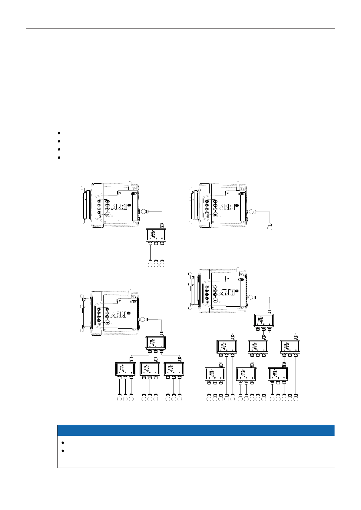
Synchronization 90
19 Synchronization
19.1 EXT Sync
Up to 16 ALEXA Mini LF cameras can be synchronized for various applications requiring sensor
synchronization. One camera is set as the master camera and the other cameras function as slave
cameras. Cameras can be connected to each other via the EXT connector, using the MINI-EXT-sync
cable (K2.0009051) and the EXT Distribution Box EDB-2 (K2.0013145).
When synchronized,
Images are captured from each camera's sensor at precisely the same time.
Recording starts and stops simultaneously on all cameras.
Recorded clips have identical start and end timecode.
SDI outputs of all cameras are synchronized.
The following image shows some sample configurations:
EXT
EXT
EXT
EXT
EXT
EXT
EXT
EXT
EXT
EXT
EXT
EXT
EXT
EXT
EXT
EXT
EXT
EXT
EXT
EXT
EXT
EXT
EXT
EXT
EXT
EXT
EXT
EXT
EXT
EXT
EXT
EXT
Slave Camera
15 Slave Cameras
9 Slave Cameras
3 Slave Cameras
NOTICE
Synchronizing sensors is possible at sensor frame rates between 20 fps and 90 fps.
The master camera does not distribute look files or frame line files. If custom look files or frame
lines are used, the files need to be imported manually on each camera.

Synchronization 91
EXT Sync Mode
One camera is functioning as the master camera and the other camera(s) as slave camera(s). A slave
camera can be a sensor slave (only sensor synchronized) or a settings slave (sensor and settings
synchronized).
1. Connect the cameras via their EXT connector using the MINI-EXT-sync cable(s) and the EXT
Distribution Box EDB-2.
Note: One EDB-2 or more are needed, if the cluster consists of more than two cameras.
2. Select MENU > System > Sensor > EXT Sync.
Following options are available:
Off EXT Sync is disabled.
EXT Master Configures the camera as the master camera. The camera has control over
one or more slave cameras. The sensors of all slave cameras will be synchro-
nized to this camera's sensor. All slave cameras will inherit the timecode from
this camera.
The master camera can be supplied with external timecode and can be syn-
chronized to an external genlock source.
EXT Sensor
Slave
Configures the camera as a sensor slave. The sensor is synchronized with
the master camera. The SDI outputs of the slave camera are synchronized
with the master camera. The slave camera inherits the timecode from the
master camera. Recording starts and stops simultaneously on all cameras.
EXT Settings
Slave
Configure the camera as a settings slave. The sensor is synchronized with
the master camera. The SDI outputs of the slave camera are synchronized
with the master camera. The slave camera inherits the timecode from the
master camera. Recording starts and stops simultaneously on all cameras. To
ensure an identical clip naming, the slave camera inherits the camera ID from
the master camera. Settings synchronized parameters include:
Project Rate Next Reel Count SDI Frame Rate
Sensor Fps Lens Squeeze Factor SDI Exposure Tool
Shutter and Shutter Unit EVF Processing SDI Peaking
Exposure Index EVF Exposure Tool SDI Overlays
White Balance* EVF Peaking Exposure Tool Settings
ND Filter EVF Overlays Frame Line Settings
Recording Codec SDI Processing Focus Unit
Recording Resolution SDI Format Noise Reduction
Active Look SDI Color Space EF Iris Value
* White balance: Whenever it is changed on the master camera, the slave
cameras will inherit the new setting. The setting inherited from the master
camera can anytime be overridden on slave camera(s) by either setting a new
value or by executing auto white balance.
Note: Configure all slave cameras first and master camera last.
Note: Parameters can only be changed from the master camera.
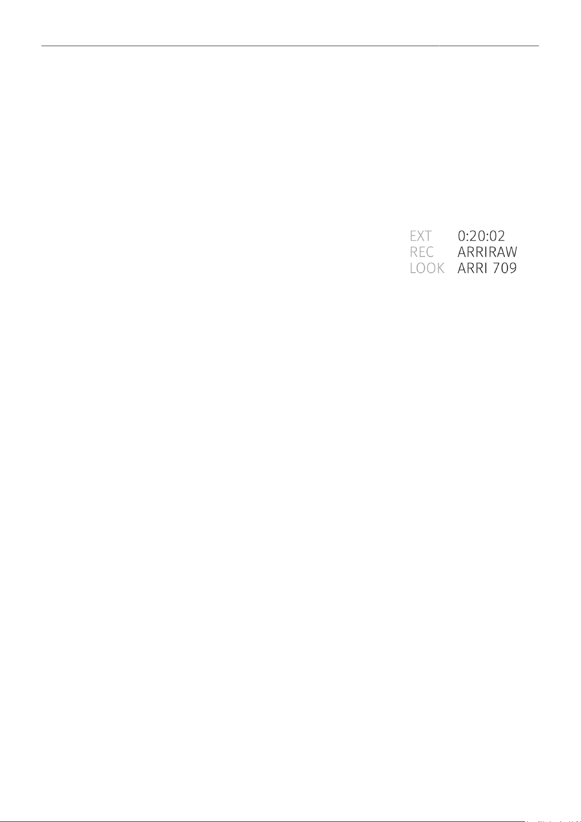
Synchronization 92
3. On the master camera in an EXT sync cluster, you need to define the amount of cameras used in
the cluster. The master camera monitors the connection to each slave camera.
On the master camera, select MENU > System > Sensor > EXT Sync Camera Count and set the
number of cameras used in your cluster (including the master camera, up to 16 cameras).
4. When using settings slaves, each camera in the setup needs to use an individual camera ID prefix.
Select MENU > Recording > Project Settings > Camera ID Prefix and select an individual prefix for
each camera (usually giving the master camera the camera ID prefix "A")
Media Status with EXT Sync
The master camera calculates the overall remaining recording
time based on the media with the lowest capacity in the cluster.
The overall remaining recording time is displayed prefixed with
EXT on the home screen and in the status info on the master
camera.
EXT Sync Info Screen
The EXT sync info screen displays the system status of all cameras in the EXT sync cluster.
Information on the camera serial numbers, the camera ID prefixes, the battery voltages and the main
status of all cameras are shown.
1. Select MENU > Info > EXT Sync Info to access the EXT Sync info screen.
Note: The EXT sync info screen lists the cameras sorted after the camera ID prefix.
Note: If one camera in the cluster is not ready to record, the entire cluster will go into idle state. Use the
EXT sync info screen to troubleshoot.
Media Erase in EXT Sync
In EXT sync mode, you can simultaneously erase the cards of all cameras in the cluster:
1. On the master camera, select MENU > Media > Erase EXT Sync Media.
A confirmation screen is displayed.
2. Press ERASE.
A progress bar indicates the progress of the master camera (only).
3. After erasing has finished, press any button to return to the menu.
EXT Sync Clip Naming
When working in EXT sync mode and the slave cameras are configured as settings slaves, clip naming
is identical to the use of a single camera.
When working in EXT sync mode and using settings sync, the slave cameras inherit the camera ID of
the master camera, so clip file names are identical. To distinguish the clip files from several cameras,
the Camera ID prefix is used. For this reason, each camera must use an individual camera ID prefix.
► Set the camera ID prefix of each camera in MENU > Recording > Project Settings > Camera ID
Prefix.
Note: The master camera will issue an alert in case duplicate camera ID prefixes are used within
the setup.
Below is a clip name example for a four camera setup, with three clips recorded. The camera ID prefix
is marked in red, the master camera ID is marked in blue. It is recommended to use the same camera
index (green) on all cameras.

Synchronization 93
A001_AH8B
A001_C001_190705_AH8B
A001_C002_190705_AH8B
A001_C003_190705_AH8B
A001_BH8B
A001_C001_190705_BH8B
A001_C002_190705_BH8B
A001_C003_190705_BH8B
A001_CH8B
A001_C001_190705_CH8B
A001_C002_190705_CH8B
A001_C003_190705_CH8B
A001_DH8B
A001_C001_190705_DH8B
A001_C002_190705_DH8B
A001_C003_190705_DH8B
Note: Do not mix sensor and settings slaves as this will cause inconsistencies in clip naming.
19.2 Genlock Synchronization
The camera's sensor and SDI outputs can be synchronized to a reference sync signal (a tri-level HD
signal or an analog black burst signal) using the SYNC IN BNC connector. The camera's sensor needs
to run at equal or double the frame rate of the reference signal to establish synchronization.
Activation of Genlock
1. Connect the genlock source to the cameras SYNC IN connector.
2. Ensure that the camera's sensor frame rate matches (or is double) the genlock source frame rate.
3. Set MENU > System > Sensor > Genlock Sync to SYNC IN.
With Genlock Sync activated, the camera displays a genlock icon on the HOME screen
and in the status info of EVF/Monitor and the SDI outputs. The icon turns orange when
the camera can not synchronize to the genlock signal or if no signal could be detected.
In this case, see MENU > Alerts for detailed information.
Note: Simultaneous use of Timecode mode Jam-sync and Genlock is not supported.
Sync Shift
The Sync Shift option applies an offset to the genlock signal at the input. Minimum step size is 52 ns,
maximum possible correction is up to +/- 20 ms (= 384000 steps), depending on the sensor frame rate.
► Select MENU > System > Sensor > Sync Shift
and apply the needed sync shift.
19.3 Timecode Synchronization
The camera's sensor and SDI outputs can be synchronized to a reference timecode signal using the 5-
pin TC connector. The camera's sensor needs to run at equal or double the frame rate of the reference
signal to establish synchronization.
Activation of Timecode Synchronization
1. Connect the timecode source to the cameras TC connector.
2. Ensure that the camera's sensor frame rate matches (or is double) the timecode source frame rate.
3. Set MENU > System > Sensor > Genlock Sync to TC IN.
With Genlock Sync activated, the camera displays a genlock icon on the HOME screen
and in the status info of EVF/Monitor and the SDI outputs. The icon turns orange when
the camera can not synchronize to the genlock signal or if no signal could be detected.
In this case, see MENU > Alerts for detailed information.
Note: Simultaneous use of Timecode mode Jam-sync and Genlock is not supported.

Sensor Settings 94
20 Sensor Settings
20.1 Noise Reduction
ARRI Noise Reduction ANR-1
ARRI Noise Reduction ANR-1 is implemented in most modern ARRI camera models and can be
used for monitoring purposes on set, recording to MXF/Apple ProRes files (baked in) or as metadata
of MXF/ARRIRAW recordings with full flexibility to change the parameter in postproduction. ARRI
Noise Reduction ANR-1 can be helpful in low light situations to reduce noise in the images. While it is
commonly available in postproduction tools, two reasons drove us towards creating a new, in-camera
ARRI noise reduction: we enable fast, in-camera noise reduction and we provide a noise reduction
method that retains the grain texture and natural looks that ARRI customers like.
Using ARRI Noise Reduction ANR-1 enables you to use noise reduction on set in the camera. This can
be helpful for low light shots, where an in-camera noise reduction is a very fast solution. Furthermore,
ARRI Noise Reduction ANR-1 gives you the possibility to combine the amount of grain with your
sharpness and detail settings for the chosen exposure directly on set.
You can store your decision either in the metadata, when recording MXF/ARRIRAW or bake it into
Apple ProRes files. In contrast to general postproduction tools, the ARRI Noise Reduction ANR-1
is optimized for the sensor noise characteristics and therefore can achieve a very natural noise
reduction without any image blurring. This noise reduction, optimized for the ARRI sensors is available
for ARRIRAW recordings by using the ARRIRAW Converter or a post-processing software that
incorporates the ARRIRAW SDK. The film grain like texture of ARRI cameras is highly appreciated by
cinematographers around the world and therefore ARRI Noise Reduction ANR-1 is moderate and does
not affect the grainy structure of the noise. The ARRI Noise Reduction ANR-1 just reduces it, nothing
more.
For more information please refer to the ARRI Texture Control White Paper, available in the White
Papers section on the ARRI website.
► Select MENU > System > Sensor > Noise Reduction to toggle noise reduction on/off.
While recording MXF/Apple ProRes files, noise reduction will be baked into the footage and therefore
MXF/Apple ProRes files cannot be opened and altered in the ARRIRAW Converter (ARC). When
recording MXF/ARRIRAW files, the ARRI Noise Reduction ANR-1 is applied for preview (viewfinder and
SDI outputs) but not baked into the footage, instead it will be stored in metadata.
20.2 Mirroring the Sensor Image
You can mirror the sensor image in horizontal and vertical directions.
► Select MENU > System > Sensor > Mirror Image.
You have the following options:
Off Mirroring is inactive.
V The sensor image is vertically mirrored.
H The sensor image is horizontally mirrored.
V+H The sensor image is vertically and horizontally mirrored (rotated by 180°).
Horizontal mirroring is applied on all output paths and internally recorded material. Vertical mirroring
is only applied to output paths; internally recorded material is not rotated, but rotation information is
written into metadata. Frame grabs of rotated images will be displayed upside down on a computer.

Sensor Settings 95
20.3 User Pixel Masking
All sensors exhibit a certain number of defect pixels, and ARRI cameras have two mechanisms to catch
and correct them: one is a static pixel correction based on a pixel mask created during manufacturing,
and the other is a dynamic pixel correction that continuously evaluates each frame and masks defect
pixels that are not caught by the static pixel mask. In very few cases, we have observed some pixels
that are not corrected by either method; for those cases User Pixel Masking is available.
User pixel masks can be created with the ARRIRAW Converter available for macOS, Windows and
Ubuntu.
When shooting ARRIRAW, it is not necessary to load the User Pixel Mask into the camera. Instead, it
can be applied to the ARRIRAW files in post using the ARRIRAW converter or any third party software
that has implemented the User Pixel Mask feature through our ARRIRAW SDK.
The User Pixel Mask will remain intact after a factory reset and after a camera software update. It can
be manually removed or overwritten with a new one at any time.
1. Select MENU > System > Sensor > User Pixel Masking.
Following options are available:
User Pixel Mask Active Shows whether a User Pixel Mask is currently active in the camera.
Install User Pixel Mask Select to install a User Pixel Mask from USB memory stick.
Export User Pixel Mask Select to backup the currently installed User Pixel Mask onto USB
memory stick.
Delete User Pixel Mask Select to uninstall a User Pixel Mask.
Grab Raw Image Stores an ARRIRAW frame grab on the USB memory stick.
User Pixel Mask Generation
1. Insert a USB memory stick into camera.
2. Select MENU > System > Sensor > User Pixel Masking > Grab Raw Frame to grab an ARRIRAW
frame.
The ARRIRAW frame grab is stored on the USB memory stick in folder ARRI/A-MINI-LF/SENSOR.
Alternatively, you can record a short ARRIRAW sequence and use that material for marking defect
pixels.
3. Import the ARRIRAW frame grab into the ARRIRAW Converter.
4. Use the ARRIRAW Converter to mark defect pixels. The marked pixel coordinates are stored in an
XML file called the User Pixel Mask. Please note that it is advisable to mark the least number of
pixels necessary, as too many marked pixels can be counter productive.
5. Save the User Pixel Mask to the USB memory stick in folder ARRI/A-MINI-LF/SENSOR.
6. Insert the USB memory stick into the camera.
7. Select MENU > System > Sensor > User Pixel Masking > Install User Pixel Mask to load the mask
into the camera.
8. After a restart of the camera, the marked pixels will be masked using information from surrounding
pixels. This masking is applied to the images delivered from the sensor, before any other
processing takes place, and thus becomes active on all outputs.
9. Carefully check the end result by visually inspecting the areas where you have marked pixels; if too
many pixels are marked too close to each other, or if pixels are marked close to other pixels that are
already marked in the static pixel mask, the result could be uncorrectable clusters, which are more
visible than the original defect pixels.

Sensor Settings 96
As an added service, it is possible to send the User Pixel Mask to ARRI Service at [email protected]
for verification. We strongly recommend that you take advantage of this free service, as sometimes,
clusters are difficult to spot depending on the background. Please note, however, that in the end, it is
the responsibility of the person creating the User Pixel Mask to verify that no clusters are formed.
NOTICE
Please note, that the User Pixel masking feature is only a temporary solution to mask defect pixels.
Defect pixels should be dealt with by sensor calibration at an ARRI service department.
A User Pixel Mask is a stopgap solution between when the defect is noticed, and when the
camera is recalibrated, to verify the sensor is still functioning within ARRI specifications and to
comprehensively assess and permanently and automatically compensate for defect pixels.
If the installed pixel masking map is deleted, the camera will be reset to its old status with all defect
pixels.

System Settings 97
21 System Settings
21.1 Language Setting
1. Select MENU > System > Language.
2. Set the language to either English or Chinese (simplified).
21.2 System Time and Date
► Select MENU > System > System Time + Date to set the system time and date.
Note: Timezone and Daylight Saving Time do not change time and date settings. They are stored
as metadata in the recorded clips.
Note: System Time and Date are reset after a camera software update.
21.3 Button and Display Settings
► Select MENU > System > Buttons + Display.
Following options are available:
Display Style
Button Brightness
Choose between day mode and night mode.
Adjust the brightness of camera and MVF buttons from 0 to 4 (0 = off)
21.4 Fan Settings
Select to set the fan mode to Low Noise for locations with ambient temperatures up to 30°C (86°F).
For locations with ambient temperatures higher than 30°C (86°F), set to Rec Low. When the fan is set
to Rec Low, it will run at a high rate when the camera is in Standby, and run at a low rate when the
camera is recording.
► Select MENU > System > Fan Mode.
Following options are available:
Rec Low Increases fan speed during standby to cool the camera. Minimizes fan
speed/noise during recording.
Note: Ideal in an environment warmer than 30 °C (86 °F).
Low Noise Minimizes fan noise during standby and recording.
Note: With data rates above 100 MB/s (due to fps/codec setting), the fan
speed automatically increases to prevent the recording media from over-
heating.
21.5 Battery Warning
You can adjust the voltage level at which a power warning is displayed for the power source connected
to the BAT connector. The level can be adjusted to match the battery type used. The default warning
value is 13.5 V.
► Select MENU > System > Power > BAT In Warning and set the warning level between 11.0 V and
34.0 V.
When the power source reaches the defined voltage level the battery display on the HOME screen
and in the status info of the viewfinder and SDI outputs start flashing.
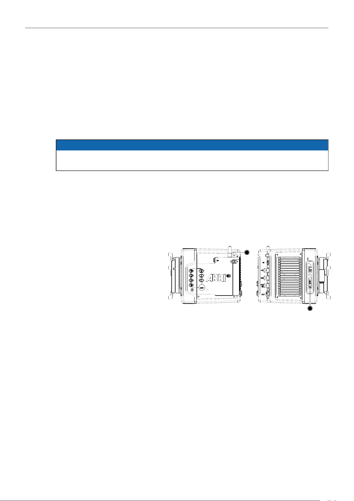
System Settings 98
21.6 Lens Mount Settings
You can enable/disable the LDS contacts of the lens mount and set your preferred focus unit.
1. Select MENU > System > Lens Mount Settings.
Following settings are available:
Focus Unit Set the unit for display of the lens focus distance to Lens Default, Metric
or Imperial.
Enable Lens Mount Enable/disable the lens contacts of a PL or EF lens mount.
NOTICE
Please note that as soon as an LDA table is activated, the LDS contacts of the lens mount are
switched off. There is no need to switch the mount off manually when using LDA.
21.7 Network and WiFi Settings
WiFi Settings
The WiFi module in the ALEXA Mini LF can be configured to act as an access point or in infrastructure
(client) mode and opens up a wireless network in the 2.4 GHz band. A WiFi connection can be used
to remote control the camera using the camera's web remote or applications communicating with the
camera via the Camera Access Protocol (CAP).
The camera is equipped with two
WiFi antennas, one external an-
tenna above the media bay (1)
and one internal antenna on the
right side front (2).
1
2
WiFi Power
► Select MENU > System > Network / WiFi > WiFi Power and set WiFi power on or off.
Additionally to the WiFi settings menu, WiFi power can be toggled by using the FN function button
or a user button assigned with WiFi Power.
WiFi Mode
1. Select MENU > System > Network / WiFi > WiFi Mode.
Following options are available:
Host The camera acts as an WiFi access point. The SSID of the camera is
"Mini-LF-SERIAL#", where SERIAL# is the five digit serial number of the camera.
Client The camera can connect to a WiFi network and receives it's IP address via DHCP.
2. Set the desired WiFi mode.
Note: the WiFi mode can only be changed while WiFi power is disabled.
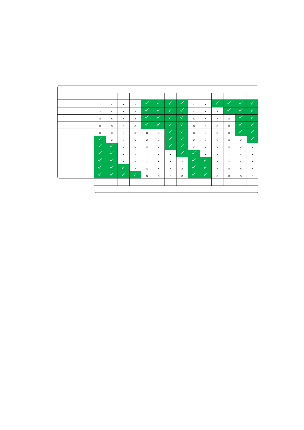
System Settings 99
WiFi Host Channel
1. Select MENU > System > Network / WiFi > WiFi Host Channel.
When using WiFi and White Radio simultaneously it is important to configure the used channels to
avoid interference and guarantee optimal performance. The following table gives an overview of
suitable channel configurations:
0
1
2
3
4
5
6
7
8
9
10
11
12
13
1
2
3
4
5
6
7
8
9
10
11
12
13
16
17
20
21
24
25
14
15
18
19
22
23
ARRI White Radio Channel Number
WiFi Channel
ZigBee IEEE 802.15.4 Radio Channel Number
2. Set the desired WiFi channel.
WiFi Password (Host Mode)
The camera uses WPA-2 encryption. You can only set the WiFi host password if the WiFi mode is set to
Host. The default password for the network is set to “arriarri”.
1. Select MENU > System > Network / WiFi > WiFi Host Password.
A screen is displayed to set your password.
2. Enter a password. The WiFi password must be between 8 and 32 characters long.
Connect to a Network (Client Mode)
You can select a WiFi network, if you have activated the WiFi power and when the WiFi mode is set to
Client. The camera allows you to join networks with WPA2 encryption or without encryption.
1. Select MENU > System > Network / WiFi > WiFi Network.
A list of available WiFi networks is displayed.
2. Select the WiFi network the camera should connect to.
If the selected WiFi network uses encryption, you are prompted to enter the password.
3. Enter the password and press CONNECT.
Connect to a Network using a QR Code (Client Mode)
You can use a QR code to connect to a WiFi network. The WiFi credentials need to be provided in the
following format:
WIFI:S:my-ssid;T:[WEP|WPA|WPA2];P:my-password;;
where the italic parts need to be replaced with your network credentials.
1. Select MENU > System > Network / WiFi > WiFi Network > SCAN QR.
2. Hold the QR-Code in front of the lens so that it fills the frame and is in focus.
A popup window with QR-Code data is displayed.
System Settings 100
3. Press CONNECT.
The camera connects with the network. The name of the network is displayed in the WiFi
NETWORKS AVAILABLE list.
Disconnect from Network (Client Mode)
1. Select MENU > System > Network / WiFi > WiFi Network.
2. Press DISCONNECT.
If the network you were connected to is hidden, it will disappear from the network list shortly after.
WiFi Status Icons on HOME Screen and in Status Info
With WiFi power enabled, the WiFi status is indicated by an icon on the "home screen" and the"status
info" of the viewfinder and the SDI outputs:
Host mode icon. WiFi power is enabled and WiFi mode is set to Host.
Client mode icon. WiFi power is enabled and connection to network has been established.
Client mode icon. WiFi power is enabled but camera is not connected to a network.
Additional information can be found under MENU > Info > Network Info .
LAN Settings
Use the ALEXA Ethernet cable (KC 153-S, K2.72021.0) to connect the camera to a router or other
devices.
LAN IP Mode
1. Select MENU > System > Network / WiFi > LAN IP Mode.
Following options are available:
Static Select for manually entering an IP address and subnet mask.
DHCP Select to let the camera accept a dynamically assigned IP address from an
DHCP server.
2. Set the desired LAN IP mode.
LAN Static IP
1. Select MENU > System > Network / WiFi > LAN Static IP.
2. Set the desired LAN Static IP adress.
LAN Static Subnet
1. Select MENU > System > Network / WiFi > LAN Static Subnet.
2. Set the desired LAN Static subnet.

System Settings 101
21.8 Reset of Electronic Horizon
1. Select MENU > System > Reset Electronic Horizon.
A screen showing the roll and tilt values is displayed.
2. Place the camera on a level surface and press RESET.
Note: A message is displayed if either the roll, the tilt or both values exceed the calibration range
and resetting is not possible.
21.9 Camera Update
21.9.1 Update of Camera Software
The camera software is updated with a USB memory stick. The Software Update Package (SUP) will
update the camera along with the Viewfinder MVF-2 and the lens mount – provided they are connected
to the camera.
The Software Update Package (SUP) can be found in the Software and Firmware Updates for Cameras
section on the ARRI website. You need to register your camera, along with your camera serial number,
to access the SUP download. Existing ALEXA customers with an active account for the download
section can use this account, unless otherwise requested.
Before update, create the folder structure on a FAT 32 USB memory stick. For more information, see
"Prepare User Storage for Use", page 47.
Preconditions
ALEXA Mini LF with MVF-2 connected
Fully charged camera battery or power supply
Computer with internet access and USB interface
USB memory stick (FAT 32 file format), prepared with the folder structure for the use with the
camera
Software Update Package Download
1. Download the software update package (SUP) from www.arri.com.
2. Double-click on the downloaded file (*.zip) to unpack it:
Update file (*.SUP)
Update key (*.lic)
Release notes
3. Carefully read the release notes.
4. Copy the update file (*.SUP) to the ARRI/A-MINI-LF/SUP folder on the USB stick.
5. Copy the update key (*.lic) to the ARRI/A-MINI-LF/LICENSES folder on the USB stick.
6. Safely remove the USB memory stick from the computer.
Camera Update
1. Open the media lid and connect the USB memory stick to the camera.
2. If inserted, remove the recording media from the camera.
3. Switch on the camera with a full battery or use a mains power supply.
4. Select MENU > Setup > Factory Reset to perform a factory reset.
5. Select MENU > System > Update > Update Camera.
6. Select the required update file and press CONFIRM to start the update.
Press CANCEL to exit.
7. Check the MVF-2 monitor for the update progress.

System Settings 102
8. Wait for the update process to finish and the camera to reboot.
After a successful update and reboot, the camera displays a success message.
Note: After an update, the timezone and daylight saving time settings of the camera are reset.
Please set them accordingly. Select MENU > System > System Time + Date.
Note: A failed camera update produces a red warning message. However, the previously installed
camera software remains intact. Press CLOSE, restart the camera and start the update again.
NOTICE
Power the camera with a fully charged battery or a power supply to avoid power loss during the
update. The update procedure takes about ten minutes.
Never shut down the camera or unplug power during the update process.
After the update, the camera reboots. Never unplug power during reboot. Check the MVF-2 for the
update status. A popup message is displayed after the update finished successfully.
21.9.2 Update of Camera Components
The camera supports to update the MVF-2 viewfinder and the lens mount. Updating the MVF-2 and the
lens mount does not require a dedicated update file. The camera will issue a message if the software
version of MVF-2 and/or the lens mount does not match the version required by the currently installed
camera SUP. In this case:
1. Select MENU > System > Update.
The Update MVF-2 and Update Lens Mount entries show the software version currently installed on
the component and the software version required by the currently installed camera SUP.
2. Select Update MVF-2 to update the MVF-2 or
Select Update Lens Mount to update the lens mount.
A confirmation screen is displayed.
3. Press CONFIRM to start the update.
The component is updated. A success message is displayed after the update has finished.
21.9.3 Update of LBUS Devices
The camera offers to update connected LBUS devices (cforce mini motors, cforce Plus motors, ARRI
Master Grips, ARRI Operator Control Unit OCU-1 and ARRI LCUBE)
1. Download the LBUS device update file from the ARRI website.
2. Copy the update file onto a USB memory stick in folder ARRI/ECS/.
3. Connect the LBUS device to the LBUS connector of the lens mount.
4. Select MENU > System > Update > Update LBUS Devices.
A list with connected LBUS devices is displayed, showing the software version currently installed on
the device and the software version stored on the USB memory stick.
5. Select the LBUS device you want to update and press UPDATE.
A confirmation screen is displayed.
6. Press CONFIRM to start the update. Cancel with BACK.

User Setups 103
22 User Setups
A user setup is a profile of the current settings on the camera that can be saved on camera and/or to
a USB memory stick. User setups can be given custom names, saved to the USB memory stick and
loaded onto multiple cameras. Rather than resetting the camera to its factory default settings, a user
setup can be used to reset the camera to a user's default settings.
User setups can be used to ensure that cameras on multi-camera shoots have matching settings, or to
transfer a show’s setup onto daily cameras, to ensure they carry the same shooting specifications.
You can also import user setups into the camera from a USB medium and export user setups to a USB
medium.
Saving a User Setup
You can save the current setup configuration in the camera or on the USB medium.
1. Select MENU > Setup > User Setups Installed > Save to save the setup in the camera.
Select MENU > Setup > User Setups on USB > Save to save the setup on the USB medium.
2. Use the onscreen keyboard to enter a name for the user setup and press SAVE.
A screen is displayed to select the setup parameter blocks. You have the following options:
General
Format
Scene
Lens
User
3. Select one or more options and press CONFIRM.
The camera stores the user setup.
Loading a User Setup
You can load user setups stored on the camera or on a USB medium.
In case you are using the ARRI WCU-4 unit, you can trigger the loading of internally stored setups from
there.
1. Select MENU > Setup > User Setups Installed to load a setup from the camera.
Select MENU > Setup > User Setups on USB to load a setup from the USB medium.
2. Select a user setup from the list and press LOAD.
A popup window with the parameter blocks of this user setup is displayed.
3. Press CONFIRM.
The camera loads the selected user setup and shows a result message. The popup highlights the
parameters that you should check in case certain parameters could not be loaded.
Factory Reset
You can reset the camera to the ARRI factory default values.
1. Select MENU > Setup > Factory Reset.
You are asked to confirm the reset.
2. Press RESET.
Note: A factory reset does not delete user setups stored/installed on camera.

User Setups 104
22.1 User Setup Parameter Blocks
The camera allows you to store a full camera configuration by selecting all parameter blocks, or only
parts of the configuration by de-/selecting the desired blocks. The parameter blocks have been chosen
to allow for maximum flexibility while keeping coherent sets of parameters and minimizing the amount
of potential conflicts by loading partial setups.
GENERAL
Groups the general camera configuration and basic project settings.
MENU > RECORDING > PROJECT SETTINGS > Project Rate
HOME > TC > OPTIONS > Timecode Options (All Settings)
MENU > RECORDING > AUDIO RECORDING > Audio (All Settings)
MENU > LOOK > LOOK > Installed Look Files
MENU > LOOK > SDI 1&2 Color Space
MENU > MONITORING > FRAME LINES > FRAME LINE > Installed Frame Line Files
HOME > FPS > Sensor FPS table
HOME > SHUTTER > Shutter table
HOME > WB > WB table
MENU > METADATA > Metadata (All Settings)
MENU > MONITORING > SDI > SDI 1&2 Format
MENU > MONITORING > SDI > SDI 1&2 Frame Rate
MENU > MONITORING > SDI > SDI 1&2 Image
MENU > MONITORING > SDI > SDI 1&2 3G Level
MENU > MONITORING > SDI > SDI2: Clone SDI1
MENU > MONITORING > SDI > Anamorphic Desqueeze
MENU > SYSTEM > SENSOR > Noise reduction
MENU > SYSTEM > SENSOR > Mirror Image
MENU > SYSTEM > SENSOR > EXT Sync
MENU > SYSTEM > SENSOR > EXT sync camera count
MENU > SYSTEM > SENSOR > Genlock Sync
MENU > SYSTEM > SENSOR > Sync Shift
MENU > SYSTEM > SENSOR > Mirror Image
MENU > SYSTEM > Fan Mode
MENU > SYSTEM > CAP Settings
MENU > ECS > RADIO > ECS Power
MENU > ECS > RADIO > ECS Radio Channel
FORMAT
Allows for easy switching between recording formats.
MENU > RECORDING > Recording Codec
MENU > RECORDING > recording Resolution

User Setups 105
MENU > MONITORING > FRAME LINES > Active frame line*
*if not found in list, load NONE
SCENE
Allows you to change quickly between different shooting situations.
HOME > FPS Sensor FPS
HOME > SHUTTER Shutter
HOME > EI Exposure Index
HOME > WB White Balance
HOME > ND ND Filter
MENU > LOOK Active Look*
*if not found in list,
then load ARRI709
HOME > EI > IRIS EF Iris Value
LENS
Allows you to change quickly between different lens setups.
MENU > RECORDING > PROJECT SETTINGS > Lens Squeeze Factor
MENU > ECS > LENS DATA > Active Lens Table
MENU > ECS > LENS DATA > Lens Tables Installed
MENU > ECS > LENS DATA > Lens Table Favorites
MENU > ECS > LBUS LENS MOTOR CONFIG > Focus Lens motor direction, torque + teeth
count
MENU > ECS > LBUS LENS MOTOR CONFIG > Iris Lens motor direction, torque + teeth
count
MENU > ECS > LBUS LENS MOTOR CONFIG > Zoom Lens motor direction, torque + teeth
count
MENU > SYSTEM > LENS MOUNT SETTINGS > Focus Unit
USER
Stores all parameters for camera personalization.
MENU > LOOK > EVF/Mon. Processing
MENU > LOOK > SDI 1 & 2 Processing
MENU > MONITORING > EVF / Monitor > Surround View
MENU > MONITORING > EVF / Monitor > Peaking Settings
MENU > MONITORING > EVF / Monitor > Settings (all, except EVF power)
MENU > MONITORING > EVF / Monitor > EVF Overlays (all settings)
MENU > MONITORING > EVF / Monitor > Monitor Overlays (all settings)
MENU > MONITORING > SDI > SDI PROCESSING > Surround View
MENU > MONITORING > SDI > SDI PROCESSING > Peaking (all settings)
MENU > MONITORING > SDI > SDI PROCESSING > Overlays (all settings)
MENU > MONITORING > Exposure Tools (all settings)

User Setups 106
MENU > USER BUTTONS > User Buttons (all settings)
MENU > SYSTEM > POWER > Bat In Warning
MENU > SYSTEM > BUTTONS + DISPLAY > Display Style, Button Brightness
PLAY > OPTIONS > Play End mode
MENU > RECORDING > REC BEEPER / TALLY > All Settings
Note: Network settings are not stored in the user setup.
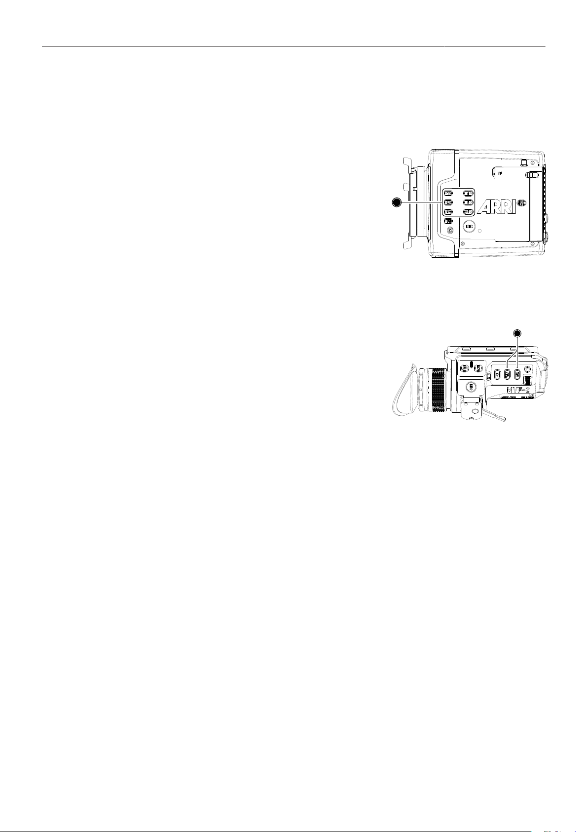
User Buttons 107
23 User Buttons
Camera User Buttons
The camera is equipped with six freely assignable user
buttons (1). Each button can be customized with individual
functions. Once a user button is assigned with a function,
press the button to trigger its function. An LED on each
user button reflects the functional status. Note: Camera
user buttons 7 and 8 can only be triggered using the Web
Remote (Beta Version).
1. Select MENU > User Buttons > Camera User Buttons.
2. Select the button you want to customize.
3. Assign the desired function from the list to the button.
1
MVF-2 User Buttons
The MVF-2 is equipped with two user buttons, VF1 and
VF2 (1). Each button can be customized with individual
functions:
1. Select MENU > User Buttons > Button VF1 or
select MENU > User Buttons > Button VF2.
2. Assign the desired function from the list to the button.
1
Additional User Buttons
In addition to camera and MVF-2 user buttons the camera supports to configure the user buttons
of electronic accessories such as the Wireless Compact Unit WCU-4, ARRI Master Grips, Operator
Control Unit OCU-1 and the GPIO box.
1. Select MENU > User Buttons.
2. Select the accessory to configure:
WCU User Buttons Up to 6 user buttons can be assigned with functions to be used
with the Wireless Compact Unit WCU-4.
LBUS Device User Buttons Up to 12 user buttons can be assigned with functions to be used
with the ARRI Master Grips and the Operator Control Unit OCU-1.
GPIO User Buttons The ARRI GPIO box (GPB-1, K.2.0007642) can be used as an in-
terface to the camera for external user buttons. It connects to the
camera via the EXT connector and has a 37-pin D-Sub connector
carrying 14 GPI (General purpose input) connections plus 2 out-
puts (camera power status and camera recording status). For ad-
ditional information, please refer to the user manual of the GPB-1.
Up to 14 user buttons can be assigned for the GPIO box.
3. Select the button you want to customize.
4. Assign the desired function from the list to the button.

User Buttons 108
Smart Behavior
Some user button functions support smart behavior. For these, a short press (i.e. less than half a
second) toggles the function, while a long press (i.e. longer than half a second) activates the function
only temporarily, as long as the user button is pressed. Assume a user button is configured with EVF
Zoom:
Short press of user button: EVF zoom is activated and stays activated. Press again to deactivate.
Long press of user button: EVF zoom function is activated while you are pressing the button,
release of the button deactivates EVF zoom.
User Button Info Screen
The camera offers a user button info screen showing the current assignment of the camera user
buttons as well as the MVF-2 user buttons.
► Select MENU > Info > User Button Info to view the current user button configuration of camera and
MVF-2 user buttons.
23.1 List of User Button Functions
Following user button functions are available:
User Button Functions
Off Disables the user button.
EVF Status Info Toggles display of EVF status info between Safe, Off and Overlay.
EVF+Mon. Check Log C Temporarily set EVF/Monitor processing to Log C. Supports smart behaviour.
EVF+Mon. Desqueeze Toggles anamorphic desqueeze on EVF and Monitor on/off.
EVF+Mon. Exp. Tool Switches the exposure tool on or off on EVF and Monitor. Supports smart behavior.
EVF+Mon. Frame Lines Switches frame lines on or off on EVF and Monitor. Supports smart behavior.
EVF+Mon. Peaking Switches peaking on or off on EVF and Monitor. Supports smart behavior.
EVF+Mon. Surround Switches surround view on or off on EVF and Monitor. Supports smart behavior.
EVF+Mon. Zebra/FC Toggles the exposure tool for EVF and Monitor between Zebra and False Color.
EVF+Mon. Zoom Switches the viewfinder zoom function on or off. Supports smart behavior.
Flip Monitor Toggles the Monitor between normal and flipped mode.
To return to automatic operation, press and hold the user button for two seconds.
SDI Check Log C Temporarily set SDI processing to Log C. Supports smart behaviour.
SDI Desqueeze Toggles anamorphic desqueeze on the SDI outputs on/off.
SDI Exp. Tool Switches the exposure tool on or off on the SDI outputs. Supports smart behavior.
SDI Frame Lines Switches frame lines on or off on the SDI outputs. Supports smart behavior.
SDI Peaking Switches peaking on or off on the SDI outputs. Supports smart behavior.
SDI Status info Toggles SDI status info between Safe, Overlay and Off
SDI Surround Switches surround view on the SDI outputs on or off. Supports smart behavior.
SDI Zebra/FC Toggles the exposure tool for the SDI outputs between Zebra and False Color.
SDI Zoom Switches the SDI zoom function on or off. Supports smart behavior.
SDI Zoom Position Toggles the SDI zoom position.
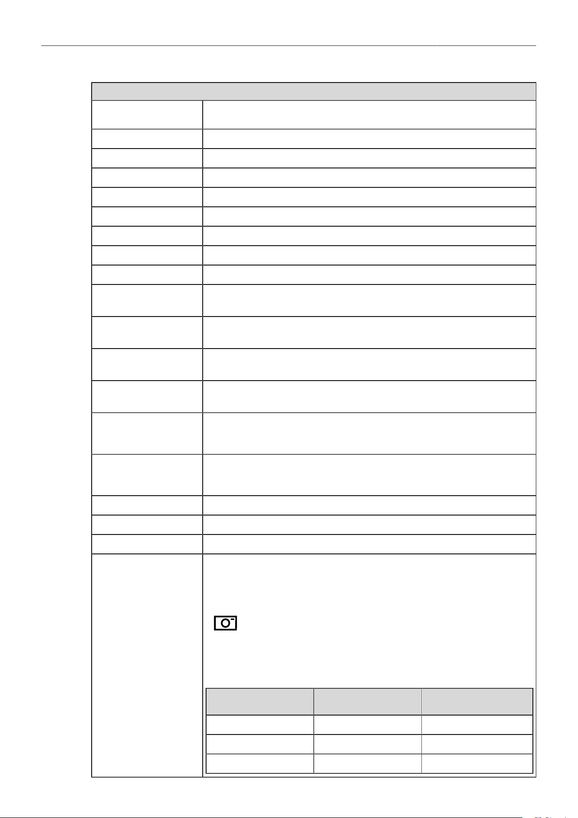
User Buttons 109
User Button Functions
SDI Zoom (smart) Press SDI Zoom to activate the zoom function on the SDI outputs. Further button presses
change the Zoom position. A button longpress exits the Zoom function.
EI Increase Selects the next value from the EI (exposure index) list.
EI Decrease Selects the previous value from the EI (exposure index) list.
FPS Increase Selects the next value from the FPS list.
FPS Decrease Selects the previous value from the FPS list.
ND Increase Selects the next value from the ND list.
ND Decrease Selects the previous value from the ND list.
Shutter Increase Selects the next value from the Shutter list.
Shutter Decrease Selects the previous value from the Shutter list.
WB Increase Selects the next value from the WB list.
Note: User button skips the Auto WB entry of the WB list.
WB Decrease Selects the previous value from the WB list.
Note: User button skips the Auto WB entry of the WB list.
Audio Ch1 Increase Increases gain of audio channel 1 in 1dB steps.
Note: User button is only functional with channel 1 control set either to Manual or Manual (+L).
Audio Ch1 Decrease Decreases gain of audio channel 1 in 1dB steps.
Note: User button is only functional with channel 1 control set either to Manual or Manual (+L).
Audio Ch1+2 Increase Increases gain of audio channels 1+2 simultaneously in 1dB steps.
Note: User button is only functional with channel 1 and channel 2 control set either to Manual
or Manual (+L).
Audio Ch1+2 Decrease Decreases gain of audio channels 1+2 simultaneously in 1dB steps.
Note: User button is only functional with channel 1 and channel 2 control set either to Manual
or Manual (+L).
Auto WB First press arms auto white balance for one second, second press triggers AWB.
Check Last Clip Plays the last five seconds of the last recorded clip.
Color Bars Turns color bar on or off. Activation works only during Stby.
Frame Grab Grabs a Log C still frame in .JPG and .DPX format and saves it to the USB medium in the
GRABS directory. Frame grabs can be stored when the camera is in STBY, REC or PLAY.
When triggered, the frame grab icon displayed on the home screen as well as the status info of
the viewfinder and the SDI outputs reflects the frame grab status:
White:
Orange:
Frame grab is stored to USB.
Frame grab failed.
Note: Frame grabs are taken from the SDI image path (including SDI settings such as process-
ing, active look and anamorphic desqueeze) but cropped to the active image area (without
black borders). The frame grab resolution depends on the SDI format (HD / UHD):
Recording Resolution Grab Resolution (SDI = HD) Grab Resolution
(SDI = UHD)
LF Open Gate 4.5K 1547 x 1076 3094 x 2153
LF 2.39:1 1906 x 795 3812 x 1590
LF 16:9 UHD/HD/2K 1920 x 1080 3840 x 2160

User Buttons 110
User Button Functions
Frame Line Color Changes the frame line color.
Iris Auto Only for use with EF lenses. Triggers automatic iris.
Iris Close Only for use with EF lenses. Closes the iris of a lens. Short press closes by 1/x stop (step size
depending on lens), long press closes by 1 stop per 0.5 seconds.
Iris Open Only for use with EF lenses. Opens the iris of a lens. Short press opens by 1/x stop (step size
depending on lens), long press opens by 1 stop per 0.5 seconds.
Button FN Behaves identically to FN button on camera body.
Note: Only available for GPIO box and Master Grip user buttons.
Button 1 to Button 3 Behaves identically to button 1, button 2 or button 3 on camera body.
Note: Only available for GPIO box and Master Grip user buttons.
Overlay Menu Activates or deactivates the overlay menu on MVF-2 EVF, monitor and SDI (when SDI process-
ing is activated).
Playback Behaves identically to the PLAY button on MVF-2.
Record Start/Stop Behaves identically to the REC button.
WiFi Power Toggles WiFi power On and Off.
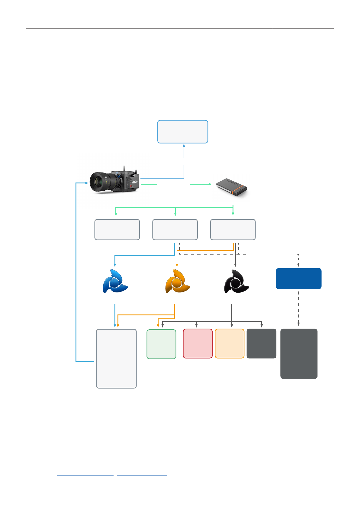
Metadata 111
24 Metadata
An ARRI camera automatically collects metadata when shooting. This metadata is stored in the header
of recorded MXF/Apple ProRes and MXF/ARRIRAW files. The data is also stored in separate Avid
Log Exchange ALE files, which keep track of all statics that are recorded on one recording media.
Additionally, ARRI cameras can record lens data dynamically frame-by-frame. Static and dynamic
metadata can be extracted e.g. from all recording formats by using ARRI Meta Extract, a free ARRI
tool.
Internal Recording
HDSDI
ARRI V3 Header
SDI stream carrying metadata
[w/o some data, e.g. look file)
Codex Compact Drive
MXF/ARRIRAW
*.mxf
Apple ProRes
*.mxf
Avid Log Exchange
*.ale | Sidecar File
Open EXR
*.exr
Open EXR
*.exr
Holds the same
metadata as a file
converted with
ARRIRAW Converter
ARRI Look File 2
*.aml
Compatible with
ALEXA Mini LF,
ALEXA LF,
ALEXA 65,
ALEXA Mini,
ALEXA SXT
and AMIRA
3rd party software
mastering/grading/vfx
Digital Picture
Exchange
*.dpx
ProRes
Quicktime *.mov
or MXF *.mxf
Container
ARRIRAW Converter
ARRI Meta ExtractARRI Color Tool
ARRI Metadata Bridge SDK
Metadata
File
*.csv
The most important metadata for post production workflow is the tape name, as it will be one of
the primary identifiers used in the EDL. The term tape name is an existing post-production naming
convention that is also used for nonlinear media. The terms tape name and reel name may be used
interchangeably. The tape name of ALEXA files is limited to 8 letters to match the CMX 3600 EDL
standard. It consists of the camera index, reel counter and the camera ID. Based on the previous
example, the tape name of the clip would be A004R18T. Even if the user forgets to assign different
camera indices to two cameras on the same project, the camera ID metadata guarantees unique tape
names.
In post-production, lens data and other metadata can be accessed and visualized directly in the
ARRIRAW Converter. ARRI Meta Extract on the other hand is able to export all metadata, audio as well
as look files from any ARRI original camera negative. The third option is the so called ARRI Metadata
Bridge (AMB), a software development kit, which can be implemented by 3rd parties to gain direct

Metadata 112
access to the embedded metadata in their tools. Through AMB we’re closely working with VFX tool
manufacturers for years now to enable and enhance their systems to auto-sense e.g. lens data in ARRI
original camera negatives and use it to trigger e.g. a de-focus effect.
For more information about ALEXA metadata, please refer to the ALEXA metadata white paper,
available in the White Papers section on the ARRI website.
Production Metadata in Camera Menu
1. Select MENU > Metadata.
Following options are available:
Production
Prod. Company
Director
Cinematographer
Camera operator
Location
Scene
Take
User info 1 & 2
2. Select the metadata field you want to edit.
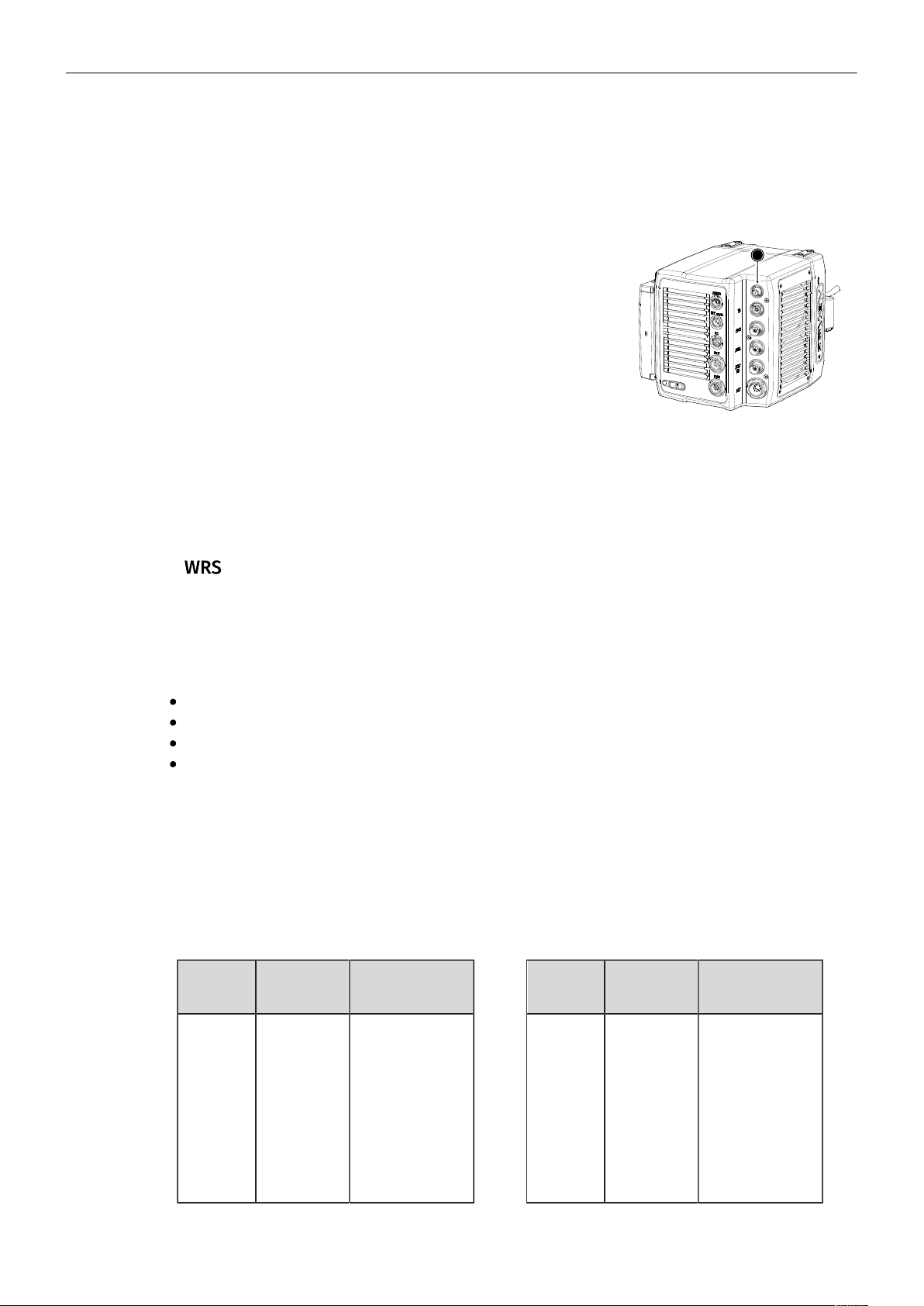
Electronic Control System (ECS) 113
25 Electronic Control System (ECS)
25.1 White Radio Configuration
The camera contains a radio unit that allows for wireless lens
control, lens data communication and remote control of basic
camera functions in combination with the ARRI Wireless Com-
pact Unit WCU-4 or ARRI Single Axis Unit SXU-1. The radio sys-
tem is called white radio. The white radio antenna connector is
located at the camera rear (1).
In order to assume a correct wireless operation, please ensure
that the white radio antenna is installed correctly on the camera.
1
Radio Power
► Select MENU > Electronic Control System (ECS) > Radio > Power
and set white radio power on or off. Per factory default, radio power is disabled.
Active white radio is indicated through the WRS (Wireless Remote System) icon
displayed on the HOME screen as well as in the status info of the viewfinder and
the SDI outputs.
Additional radio information is displayed in two status entries in the white radio submenu:
► MENU > Electronic Control System (ECS) > Radio > Status shows the current status of the white
radio module:
Off (white radio disabled)
Init (white radio initializing)
Ready (white radio initialized and ready to be used)
Blocked (selected white radio channel is already used by another camera on set)
► MENU > Electronic Control System (ECS) > Radio > Connected Devices displays the amount of
hand units connected to the camera. Up to three hand units can connect to one camera in parallel.
White Radio Channel
The white radio module offers 14 channels to choose from.
► Select MENU > Electronic Control System (ECS) > Radio > Channel and set the white radio
channel:
Channel Frequency ZigBee IEEE
802.15.4 Channel
0
1
2
3
4
5
6
2.410 GHz
2.415 GHz
2.430 GHz
2.435 GHz
2.450 GHz
2.455 GHz
2.470 GHz
12
13
16
17
20
21
24
Channel Frequency ZigBee IEEE
802.15.4 Channel
7
8
9
10
11
12
13
2.475 GHz
2.420 GHz
2.425 GHz
2.440 GHz
2.445 GHz
2.460 GHz
2.465 GHz
25
14
15
18
19
22
23
Note: Make sure to set the white radio channel accordingly on the hand unit.
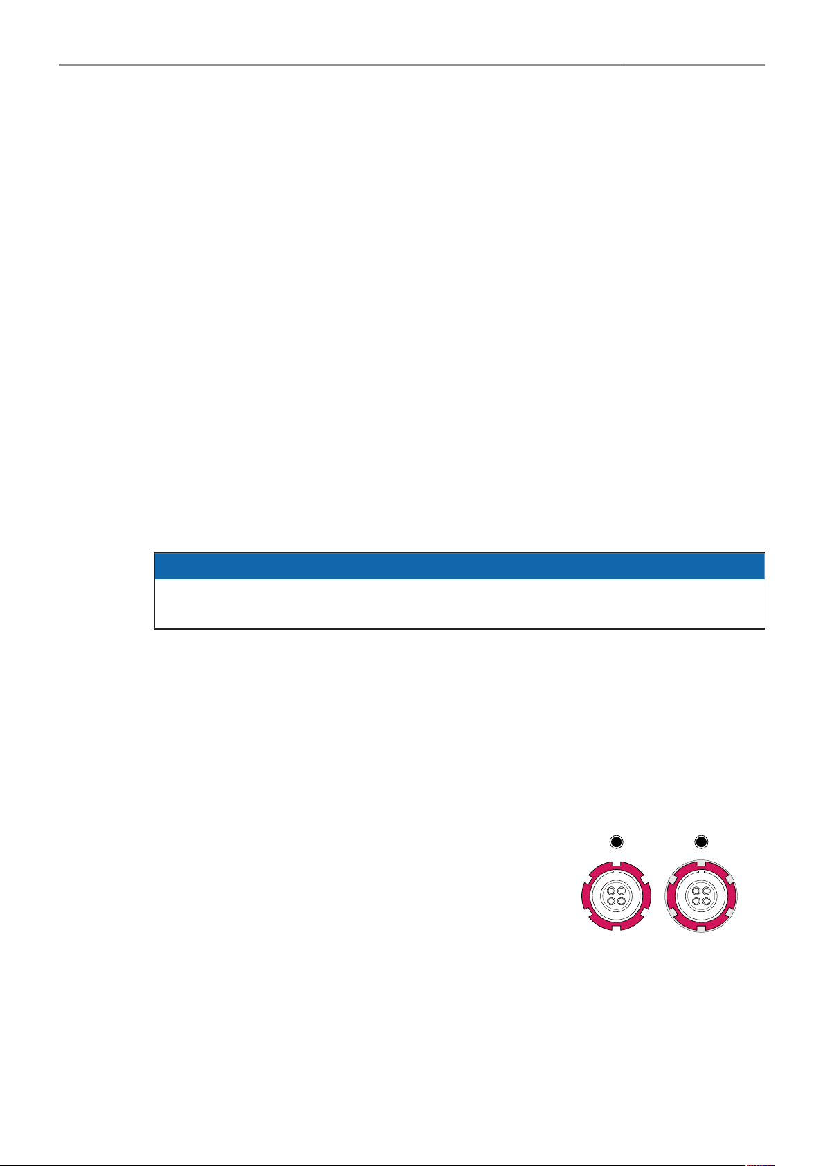
Electronic Control System (ECS) 114
Note: Make sure that each camera on set uses its own white radio channel.
Note: It is not supported that one hand unit connects to two cameras in parallel.
Note: When using white radio and WiFi simultaneously it is important to configure the used
channels to avoid interference and guarantee optimal performance. See the channel configuration
table in the WiFi chapter "WiFi Host Channel" for more information.
Wireless Region Setting
The wireless region setting specifies the region the white radio can be used in compliance with local
regulations.
1. Select MENU > Electronic Control System (ECS) > Radio > Wireless Region Setting.
The following options are available:
Australia
Canada
China
Egypt
Europe
Hong Kong
India
Israel
Japan
New Zealand
Philippines
Singapore
South Africa
South Korea
Taiwan
Thailand
UAE
USA
World
2. Set the region the white radio is used in.
NOTICE
Please ensure that the region is configured correctly, as it may be illegal to use white radio in a
region other than specified in the setting. All settings are compliant to FCC and IC regulations.
Connect a Hand Unit to the Camera
► Make sure camera and hand unit are set to use the same white radio channel and wireless region.
The hand unit connects automatically to the camera.
25.2 Lens Motors
The ALEXA Mini LF supports the use of cforce mini and cforce plus lens motors. Lens motors are
connected to the LBUS connector of the lens mount and can be daisy chained. The motors can be hot
plugged, no need to switch off the camera.
When connecting a cforce plus motor to the camera please make
sure that the LBUS connector(s) on both motor and lens mount
are equipped with a silver washer placed below the red nut (2) of
the connector.
If the LBUS connectors on either cforce plus motor or lens mount
(or both) miss the silver washer (1), the cforce plus motor needs
to be supplied with external power (e.g. D-Tap from a battery
adapter plate) in order to ensure proper performance.
Note: cforce mini motors are not affected and can always be
powered through the lens mount.
1
2
Motor Calibration
After connecting a lens motor to the camera it must be calibrated.

Electronic Control System (ECS) 115
The camera indicates the calibration request by displaying the CAL icon on the home
screen as well as in the status info of the viewfinder and the SDI outputs.
► Select MENU > Electronic Control System (ECS) > Calibrate All Motors to start calibration of all
connected lens motors.
Additionally, motor calibration can be triggered through the hand unit or the motor itself.
NOTICE
Do not trigger a calibration unless all connected motors are attached to the lens.
Lens Motor Configuration
1. Select MENU > Electronic Control System (ECS) > LBUS Lens Motor Configuration.
The following options are available:
Focus/Iris/ Zoom
Motor Torque
Set the torque of a lens motor, available values in the range of 1 (lowest)
to 4 (highest).
Focus/Iris/Zoom
Motor Direction
Available values are Left and Right. Set direction according to motor po-
sition when standing behind the camera.
Focus/Iris/Zoom
Motor Teeth Count
Selects the number of teeth of the motor. Available values are Auto, 40t,
50t, and 60t.
The motor teeth count setting is only active when a LDA lens table is ac-
tive and is used to assure correct lens table mappings when using a dif-
ferent motor gear than the one the lens table was initially created with.
You may have to change the direction of the Focus, Iris, and Zoom axis motor depending on the
mounting position of the motor (left/right side or top/bottom).
25.3 Lens Data
Lens data can be provided in two different ways, depending on the type of lens:
LDS Lenses
These lenses contain an integrated electronic interface that sends information about focus, iris and
zoom directly to the camera.
Non-LDS Lenses
These lenses do not have an LDS interface, hence information about focus, iris and zoom need to
be gathered from lens motors and translated into sensible values with the help of lens tables. These
lens tables are stored in the camera internal Lens Data Archive (LDA).
Lens Data Archive (LDA)
The LDA contains lens tables which offer lens data functionality with non-LDS lenses in connection with
lens motors. It is possible to add or delete lens tables from the lens data archive. You can transmit LDA
files that are stored on the SD card of the WCU-4 wirelessly to the camera. There is no need to copy
the files from the WCU-4 SD card to USB and then to the camera.
When a non-LDS lens is connected, the user can achieve LDS functionality by using the Lens Data
Archive. In the LDS screen, a button labeled LDA appears when a non-LDS lens is connected. The
LDA screen consists of a user list and a main archive list. The user list should only contain the lenses
currently used to achieve quick access to the desired lens tables. The main archive contains a set
of lens tables for ARRI/Zeiss High Speeds (also known as Super Speeds), Master Primes and Ultra
Primes and can be extended with additional lens tables for any PL-Mount lens.
For information on how to generate a lens table please see the Wireless Compact Unit WCU-4 user
manual.

Electronic Control System (ECS) 116
Note: It is possible to load a lens table even when an LDS lens is attached. The LDA values calculated
from motor positions and lens tables take precedence over the values communicated by the lens itself.
This can be necessary, if the lens data from the lens is faulty or imprecise.
NOTICE
Please note that as soon as a LDA table is activated, the LDS contacts of the lens mount are
switched off. There is no need to switch the mount off manually when using LDA.
25.3.1 Adding Lens Tables (LDA)
1. Select MENU > Electronic Control System (ECS) > Lens Data > Lens Tables Installed > ADD.
2. Press IMPORT to import lens tables from a USB medium or DEFAULTS to select a lens table from
the internal lens tables default list.
3. Select the desired lens table from the list and press IMPORT.
The lens table is imported to the cameras Lens Tables Installed list.
4. To use the lens table, select the lens table from the Lens Tables Installed list and press SET.
Some lens tables contain different scale classes for the same model. The scale class of an
individual lens is engraved on the lens barrel. If required: select the corresponding scale class from
the list.
Lens Tables Favorites List
Frequently used lens tables can be added to a favorites list. The list shows all lenses that have been
added before, including the selected scale class.
Add Lens Tables to the Favorites List
1. Select MENU > Electronic Control System (ECS) > Lens Data > Lens Tables Installed and select
and set a lens table for use.
2. Select MENU > Electronic Control System (ECS) > Lens Table > Add to Favorites to add the lens
table to the favorites list.
Select a Lens Table from the Favorites List
1. Select MENU > Electronic Control System (ECS) > Lens Data > Lens Table Favorites.
A list with favorite lens tables is displayed.
2. Select and set a lens table from the list.
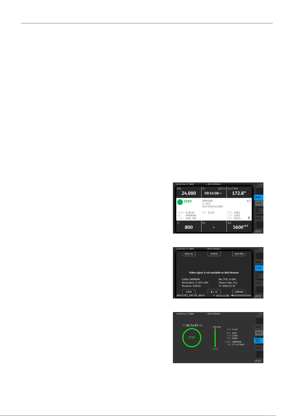
Remote Control 117
26 Remote Control
26.1 Wireless Control Unit WCU-4
The WCU-4 is an all-inclusive and yet affordable hand unit offering up to 3-axis lens control. It includes
a newly designed, super-smooth focus knob with adjustable friction and backlit, optionally pre-
marked focus rings that are well readable in the dark without distracting performers. The whole unit is
completely splash proof for ARRI-typical reliability. The slider has its scale on the 3” display, providing
clearly readable T-stop numbers and optional on-screen markings. If preferred, the slider can be also
set to show zoom scales. With the additional ALEXA Remote license, the WCU-4 shows extended
camera status information and allows changing camera parameters from the remote unit.
26.2 Web Remote (Beta Version)
ALEXA Mini LF has a web remote function for full remote control of the camera with a web browser.
The web remote requires a connection to the camera via WiFi or Ethernet (with ALEXA Ethernet/RJ-45
Cable KC-153-S, K2.72021.0).
WiFi is enabled per factory default, If WiFi is inactive, enable WiFi via the MVF-2 in MENU > System >
Network / WiFi > WiFi Power. Without the MVF-2 connected enable WiFi by pressing Function button
FN and camera button 6.
The web remote is divided into the following four sections:
MAIN
Shows the same user interface as the MVF-2, ex-
cept for the live screen. Click/tap the screen but-
ton tabs to enter a screen/trigger a function. Slide
to the left to access the camera menu.
PLAY
Starts playback from the recording media. Pro-
vides the same controls as the MVF-2, but does
not show a video signal.
REC INFO
Contains information on the main recording pa-
rameters, plus a REC button. Click the big circle
icon to start/stop recording.
Note: Rec status and timecode may respond
slightly delayed depending on the network's
speed.
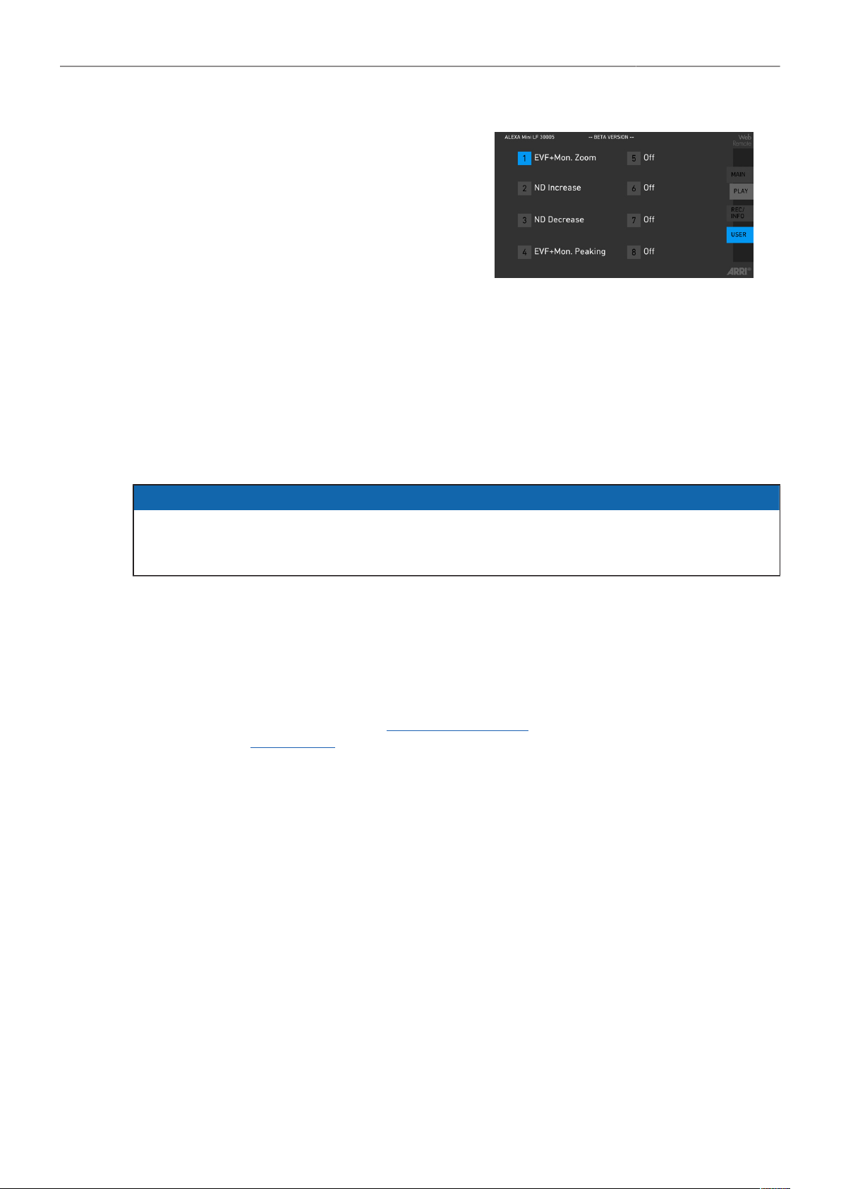
Remote Control 118
USER
Shows configuration of the camera user buttons
and allows you to trigger them. Press the number
icons to trigger the user buttons.
Access to Web Remote
► Open a web browser and enter the URL: http://mini-LF-xxxxx.local (replace xxxxx with your
camera's 5-digit serial number).
To use the web remote function via this URL, the device must support zero-configuration networking
(zeroconf), e.g. through Apple Bonjour. Without zeroconf, the web remote can be reached via the
network's IP address (WiFi or LAN IP). The WiFi IP is fixed to 192.168.153.1. The LAN IP can be
either assigned from a DHCP server or configured manually, and can be checked with an MVF-2 in
MENU > Info > Network Info.
NOTICE
Frequent reloading of the web remote camera interface connected with WiFi indicates a limited WiFi
range. Please place the device closer to the camera or connect via Ethernet. You may also consider
to use the WiFi client mode which allows connecting the camera to a WiFi network.
26.3 Camera Access Protocol (CAP)
The Camera Access Protocol (CAP) is an IP based API used to control and monitor ARRI cameras
via a network connection. The protocol incorporates functions to perform color grading, query and set
values like exposure index or sensor frame rate, start and stop recording and many more. It is currently
available for ALEXA LF, ALEXA Mini LF, ALEXA 65, ALEXA SXT, ALEXA Mini and AMIRA cameras.
Information on the Camera Access Protocol is available through the ARRI partner program free of
charge. For more details please see our ARRI Partner Program and the Camera Access Protocol
Feature List in the White Papers section on the ARRI website.
Activation of CAP Server
► Select MENU > System > Camera Access Protocol (CAP)
to switch remote access to the camera via the Camera Access Protocol on or off.
CAP Server Password
1. Select MENU > System > Camera Access Protocol (CAP) > Cap Server Password.
2. Use the on-screen keyboard to enter a password used for Camera Access Protocol connections.
CAP Client List
The CAP client list shows the name of the currently connected client. The list shows 'NONE' if no client
is connected, and 'NO NAME' if the connected client has not transmitted its name.
► Select MENU > System > Camera Access Protocol (CAP) > CAP Client List
to display the list.
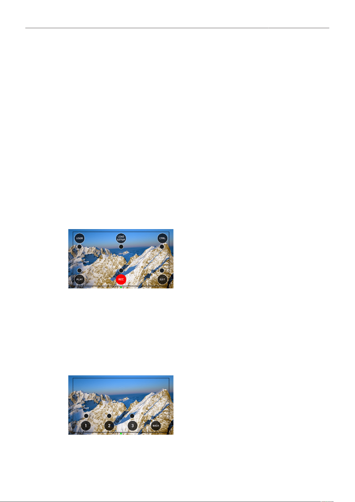
Transvideo Starlite HD5-ARRI Monitor 119
27 Transvideo Starlite HD5-ARRI Monitor
The Transvideo Starlite HD5-ARRI monitor (K2.0006960) is a 5" 3G-SDI OLED monitor with an
integrated H.264 recorder, a touchscreen and a special ARRI bus interface to communicate with the
camera. It allows basic operation of the camera. All overlays required for touch operation are generated
by the camera and transferred to the Starlite monitor via HD-SDI. For this reason, monitors daisy-
chained to the Starlite will show the overlays as well.
Connection to Camera
1. Connect the monitor to an SDI output of the camera.
Make sure the SDI image of the output is configured to Processed, not Clean. For more information,
see SDI Image.
2. Connect the power cable (Lemo 5-pin to Lemo 6-pin):
Connect the Lemo 5-pin plug to the POWER connector of the monitor.
Connect the Lemo 6-pin plug to the EXT connector of the camera.
Main Menu
► Activate the menu by pressing the blue "A" touch icon on the monitor.
The main screen opens up:
1
3
4
6
2
5
► Press USER (1) to access the user button menu.
► Press LOAD SETUP (2) to load a user setup from the list of
installed user setups on the camera.
► Press CTRL (3) to activate the overlay menu.
► Press PLAY (6) to start playback.
► Press REC (5) to start or stop recording.
► Press EXIT (4) to exit the ARRI menu and to return to the
standard Starlite mode.
Note: All overlays disappear after a few seconds of inactivity.
User Button Menu
In the user button menu, the same functions are available as with the camera user buttons (1) to (3).
1. Activate the menu by pressing the blue "A" touch icon on the monitor.
2. Press USER to access the user button menu.
The user screen is displayed:
1
2
3
► Press the buttons to toggle the assigned user button function.
► A gray button indicates an active function.
► Return to the main menu by pressing the BACK icon.
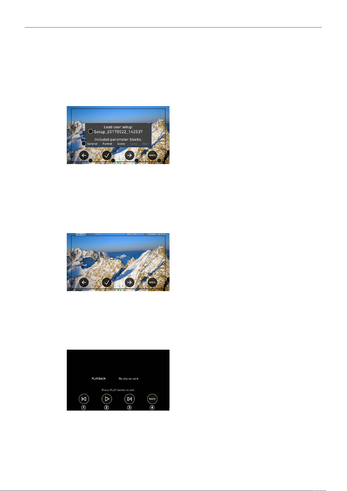
Transvideo Starlite HD5-ARRI Monitor 120
User Setup Menu
In the load user setup menu, you can load user setup files that have been stored on the camera.
1. Activate the menu by pressing the blue "A" touch icon on the monitor.
2. Press LOAD SETUP to load a user setup from the list of installed user setups on the camera.
The user setup screen is displayed:
1
2
3
4
5
6
► Select the user setup file to be loaded (1) with the left (3) and
right (5) arrow buttons.
► Confirm the selection of the user setup file by pressing the
checkmark (4).
► Cancel user setup loading and return to the main menu by
pressing BACK (6).
Control Menu
In the control menu, the main camera parameters can be edited similar to the Overlay Menu.
1. Activate the menu by pressing the blue "A" touch icon on the monitor.
2. Press CTRL to activate the overlay menu.
The control screen is displayed:
► Select a parameter by pressing the touch icon (1) or (3) to
move the selection rectangle left or right.
► Select the parameter by pressing the touch icon (2).
► Edit the parameter by pressing the touch icons (1) or (3).
► End editing by pressing the touch icon (2).
► Exit the control menu by pressing the BACK (4) icon.
Playback Menu
1. Activate the menu by pressing the blue "A" touch icon on the monitor.
2. Press PLAY to start playback.
The playback screen is displayed:
► Play or pause a clip by pressing the PLAY touch icon (2).
► Skip to previous or to next clip by pressing the Skip previous
(1) or Skip next (3) touch icons.
► While playback is running, press Fast backward (1) or Fast
forward (3) to decrease or increase playback speed.
► Exit playback and return to the main menu by pressing the
BACK touch icon (3).
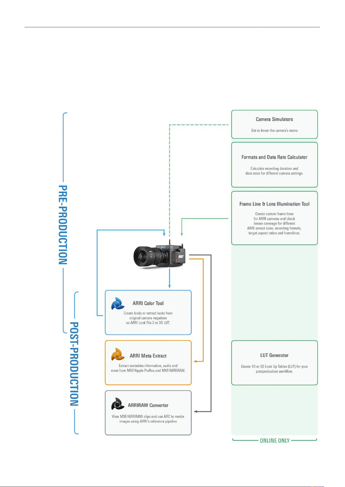
Appendix 121
28 Appendix
28.1 Companion Tools
ARRI maintains various tools to support your work with the ALEXA Mini LF on- and off-set. In the
following overview, some of the tools are highlighted “online only” (green border) the others are
available as download for Linux, macOS or Windows.

Appendix 122
Frame Line & Lens Illumination Tool
The Lens Illumination Tool is an interactive visual guide that shows how different lenses illuminate
different sensor modes and target aspect ratios of ARRI ALEXA, ALEXA Mini, ALEXA Mini LF and
AMIRA cameras. The LIT is meant as a first step, and as a guide only - we strongly recommend
that you shoot your own tests to determine the exact behavior of the lenses you plan to use. Each
lens type is designed to cover a certain image circle, within which the manufacturer upholds image
quality criteria, including illumination. Lenses still show an image outside of this image circle, but of an
undefined image quality. Farther out from the image circle there is a point at which there is no more
light, defining the 'illumination circle'. The size of the illumination circle changes based on lens design,
focal length, focus setting and iris setting, which is why we have provided tools for playing around
with all those parameters. All lenses are brighter, and have a better image quality in the center than
in the corners, though light distribution differs vastly between lenses. This guide allows you to take a
look at how much illumination there is within a given sensor mode and target aspect ratio. The guide
only shows illumination and not any other image quality parameter. It was created by shooting a gray
chart with each lens as a rough guide; please note that based on image content your results may vary.
For each lens type and focal length, the chart was created by using one particular physical lens (not
design data), and we display the serial number of that lens. Based on the manufacturing tolerances
and service history of the lenses out there, your results may also vary. The tool accommodates ARRI
Signature Primes, the ARRI Ultra Wide Zoom, all ARRI Master Primes (except the 14mm Master
Prime), the ARRI Master Macro, all ARRI Ultra Primes, the ARRI Alura Studio and Lightweight Zooms,
and the Cooke Mini S4 18, 25, 32 and 40mm. It’s also now possible to upload frame lines (created by
you, or other users, with the ARRI Frameline Composer) into the LIT. This enables direct comparisons
between different lenses within the particular frame lines.
► Frame Line & Lens Illumination Tool
Formats and Data Rate Calculator
The ARRI Formats and Data Rate Calculator (FDRC) is an online tool that calculates the record
duration and data rates for different camera settings (combinations of camera model, codec, resolution,
project rate, sensor speed, recording media, audio on/off). It also gives deeper insight into available
recording formats and camera modes. The section “Format Preview” lists the sensor and recording
resolution for each recording format as well as a graphical preview for both sensor and recorded clip.
► Formats & Data Rate Calculator
LUT Generator
Generally speaking LUTs (Look Up Tables) are used to manipulate image data. The LUT transforms a
digital signal to adjust the sensitivity, gamma and provide a color correct monitoring input. Nowadays
on-set color correction is not a novelty anymore, nevertheless Look Up Tables are still needed to
convert ARRI’s Log C to a viewable format (e. g. REC 2020 or REC 709) or an otherwise needed
format (conversion to linear space for VFX). Our LUT Generator can create the LUT you need.
► LUT Generator
Camera Simulator
The camera simulator is an interactive learning tool to familiarize yourself with the menu navigation of
ARRI digital cameras. The main user interface on the viewfinder shows a simulation of the real camera.
If you choose „Explorer“ from the top-bar you can explore all bits and pieces around the camera, its
connectors as well as the viewfinder. Get started now and learn first hand the simple, straightforward
menu system that only the ARRI digital cameras offer.
► Camera Simulators

Appendix 123
ARRIRAW Converter
The ARRIRAW Converter (ARC) is ARRI`s free reference tool for processing MXF/ARRIRAW or
ARRIRAW files to render images of optimal quality. It contains ARRI`s Software Development Kit (SDK)
which is also used in the postproduction tools Adobe, Autodesk, Blackmagic, Colorfront, FilmLight,
Filmmaster, Nablet AVID AMA PlugIn, The Foundry, and many others. Use the ARRIRAW Converter to
Create projects with bins and sequences
Display ARRIRAW and MXF/ARRIRAW files using individual processing settings
Apply different looks on the footage
Display metadata
Render files to one of the common formats for post-production such as OpenEXR, DPX or
QuickTime/ProRes or to transcode MFX/ARRIRAW files into ARRIRAW files
► ARRIRAW Converter
ARRI Meta Extract
ARRI's digital cameras can acquire metadata during recording. Metadata not only describes the
file itself but can transport other information like details on the camera settings, sensor speed or a
look file. These static types of metadata can be combined with dynamic metadata where the values
change while shooting – like lens data information from the Lens Data System. The complete metadata
information is stored in ALEXA or AMIRA output formats: ARRIRAW, MXF/ARRIRAW, ProRes and
DNxHD. Also, the sidecar files *.ale and *.xml carry some of that information. ARRI Meta Extract
is available as a GUI (graphical user interface) for Mac OS X, Windows x64, Ubuntu or as CMD
(command line) application for Mac OS X, Windows x64, Cent OS, Ubuntu and SLES.
► ARRI Meta Extract
ARRI Color Tool
ARRI Color Tool is a free utility for creating the new ARRI Look File 2 for ALEXA LF, ALEXA SXT,
ALEXA 65, ALEXA Mini, ALEXA Mini LF and AMIRA cameras. You can use the ARRI Color Tool to
create a completely new look or modify an existing look based on Log C Apple ProRes clips or Log C
*.dpx grabs from all ARRI cameras. Some 3rd party post processing tools do not support ALF-2 looks
natively. ACT allows one to export 3D LUTs in order to be compatible with these tools. ACT is available
for Mac OS X and Windows x64.
► ARRI Color Tool
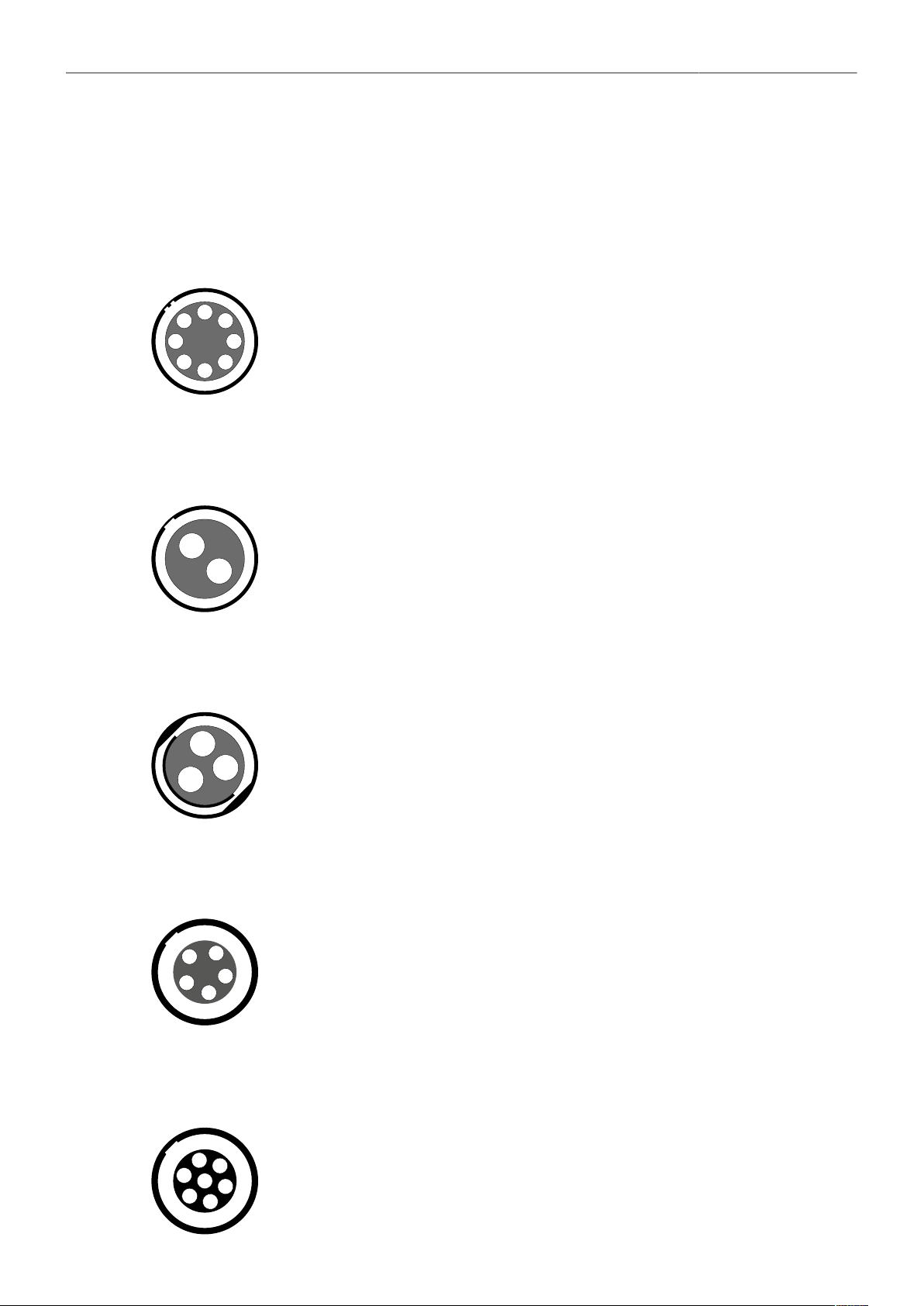
Appendix 124
28.2 Connector Pin-Outs
Note: All pin-outs for camera interfaces appear as seen by the user.
BAT
Connector ID: LEMO EEJ.2B.308
1
2
3
4
5
6
7
8
1 Batcom
2 Powergnd
3 Powergnd
4 Powergnd
5 Batcom Gnd
6 Batplus
7 Batplus
8 Batplus
12 V
Connector ID: LEMO EEG.0B.302.CLN.A365
1
2
1 GND
2 12 V Aux
RS
Connector ID: Fischer DPB102A052-130
1
3
2
1 GND
2 24 V Aux
3 R/S
TC
Connector ID: LEMO EEG.0B.305
2
4
3
1
5
1 GND
2 LTC In
3 Aux
4 Aux
5 LTC Out
EXT
Connector ID: LEMO EEG.1B.307
2
4
3
1
5
6
7
1 Can1 H
2 Can1 L
3 Can2 H
4 Can2 L
5 24V Aux
6 GND
7 R/S
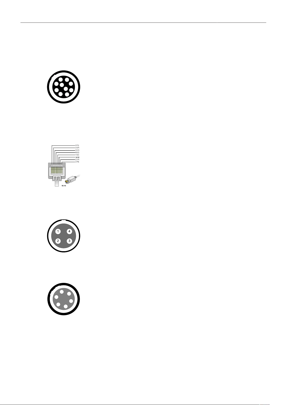
Appendix 125
Ethernet (Camera Side)
Connector ID: LEMO EEG.1B.310
2
3
1
6
7
4
5
8
9
10
1 MX-1P CTS (white-orange)
2 MX-1N DTR (orange)
3 MX-2P GND (white-green)
4 MX-2N DCD (green)
5 MX-3P TXD (blue)
6 MX-3N RXD (white-blue)
7 MX-4P DSR (white-brown)
8 MX-4N RTS (brown)
9 GND
10 Proprietary - do not use
Ethernet (PC Side)
Connector ID: RJ 45
RTS brown
DSR white-brown
DCD green
RXD white-blue
TXD blue
GND white-green
DTR orange
CTS white-orange
LBUS (on Lens Mount)
Connector ID: LEMO EEG.0B.304
1 GND
2 Can L
3 VBat
4 Can H
Audio
Connector ID: LEMO EEG.0B.306.CLN
2
3
4
5
6
1
1 GND
2 CH 1 (+)
3 CH 1 (-)
4 CH 2 (+)
5 CH 2 (-)
6 12 V

Appendix 126
Audio Cable K2.0023988
ARRI offers an ALEXA Mini LF audio cable with a matching connector to create audio adapters. The
following table shows the wire assignments of this cable.
Function Wire
GND
CH 1 (+)
CH 1 (-)
CH 2 (+)
CH 2 (-)
12 V
black
blue
brown
yellow
green
red
Headphone out (on MVF-2)
Connector ID: 3,5 mm TRS jack
4
2
TIP
3
RING
1
GND
GND
1 GND
2 GND
3 R Out
4 L Out

Appendix 127
28.3 Technical Data
Sensor Type Large Format ARRI ALEV III (A2X) CMOS sensor with Bayer pattern color
filter array
Sensor Size 36.70 x 25.54 mm / 1.444 x 1.005"
Ø 44.71 mm / 1.760"
Photosite Pitch 8.25 μm
Sensor Frame Rates 0.75 - 90fps
Sensor Active Image Area (photosites)
LF Open Gate ProRes 4.5K:
LF Open Gate ARRIRAW 4.5K:
LF 16:9 ProRes HD:
LF 16:9 ProRes 2K:
LF 16:9 ProRes UHD:
LF 16:9 ARRIRAW UHD:
LF 2.39:1 ProRes 4.5K:
LF 2.39:1 ARRIRAW 4.5K:
4448 x 3096
4448 x 3096
3840 x 2160
3840 x 2160
3840 x 2160
3840 x 2160
4448 x 1856
4448 x 1856
Sensor Active Image Area (dimensions)
LF Open Gate ProRes 4.5K: 36.70 x 25.54 mm
1.445 x 1.006"
LF Open Gate ARRIRAW 4.5K: 36.70 x 25.54 mm
1.445 x 1.006"
LF 16:9 ProRes HD: 31.68 x 17.82 mm
1.247 x 0.702"
LF 16:9 ProRes 2K: 31.68 x 17.82 mm
1.247 x 0.702"
LF 16:9 ProRes UHD: 31.68 x 17.82 mm
1.247 x 0.702"
LF 16:9 ARRIRAW UHD: 31.68 x 17.82 mm
1.247 x 0.702"
LF 2.39:1 ProRes 4.5K: 36.70 x 15.31 mm
1.445 x 0.603"
LF 2.39:1 ARRIRAW 4.5K: 36.70 x 15.31 mm
1.445 x 0.603"
Recording File Container Size (pixel)
LF Open Gate ProRes 4.5K:
LF Open Gate ARRIRAW 4.5K:
LF 16:9 ProRes HD:
LF 16:9 ProRes 2K:
LF 16:9 ProRes UHD:
LF 16:9 ARRIRAW UHD:
LF 2.39:1 ProRes 4.5K:
LF 2.39:1 ARRIRAW 4.5K:
4480 x 3096
4448 x 3096
1920 x 1080
2048 x 1152
3840 x 2160
3840 x 2160
4480 x 1856
4448 x 1856
Exposure Latitude 14+ stops over the entire sensitivity range from EI 160 to EI 3200 as mea-
sured with the ARRI Dynamic Range Test Chart (DRTC-1)
Exposure Index Adjustable from EI 160-3200 in 1/3 stops, EI 800 base sensitivity
Shutter Electronic shutter, 5.0°- 356° or 1s - 1/8000s

Appendix 128
Recording Formats MXF/ARRIRAW
MXF/Apple ProRes 4444 XQ
MXF/Apple ProRes 4444
MXF/Apple ProRes 422 (HQ)
Recording Media Codex Compact Drive™
Recording Frame Rates
LF Open Gate ProRes 4.5K:
LF Open Gate ARRIRAW 4.5K:
LF 16:9 ProRes HD:
LF 16:9 ProRes 2K:
LF 16:9 ProRes UHD:
LF 16:9 ARRIRAW UHD:
LF 2.39:1 ProRes 4.5K:
LF 2.39:1 ARRIRAW 4.5K:
0.75 - 40 fps
0.75 - 40 fps
0.75 - 90 fps
0.75 - 90 fps
0.75 - 60 fps
0.75 - 60 fps
0.75 - 60 fps
0.75 - 60 fps
Recording Modes Standard real-time recording
Viewfinder Type Multi Viewfinder MVF-2 with 4,0" flip-out monitor and CoaXPress interface
Viewfinder Technology OLED viewfinder display LCD flip-out monitor
Viewfinder Resolution (pixel) 1920 x 1080
Viewfinder Diopter Adjustable from -5 to +5 diopters
Color Output Rec 709
Rec 2020
Log C
Custom Look (ARRI Look File ALF-2)
Look Control Import of custom 3D LUT
ASC CDL parameters (slope, offset, power, saturation)
White Balance Manual and auto white balance, adjustable from 2000K to 11000K in 10K
steps Color correction adjustable range from -16 to +16 CC 1 CC corre-
sponds to 035 Kodak CC values or 1/8 Rosco values
Filters Built-in motorized ND filters 0.6, 1.2, 1.8
Fixed optical low pass, UV, IR filter
Image Outputs 1x proprietary signal output for MVF-2 viewfinder on VF CoaXPress con-
nector
2x SDI outputs on BNC connectors:
SDI 1: 1.5G 422 HD
3G 422 HD
3G 444 HD
(SMPTE ST292-1, up to 30 fps)
(SMPTE ST425-1, up to 60 fps)
(SMPTE ST425-3, up to 30 fps
SDI 2: 1.5G 422 HD
3G 422 HD
3G 444 HD
6G 422 UHD
(SMPTE ST292-1, up to 30 fps)
(SMPTE ST425-1, up to 60 fps)
(SMPTE ST425-3, up to 30 fps)
(SMPTE ST2081-10, up to 30 fps)
Both SDI outputs carry uncompressed video with embedded audio and
metadata.
SDI1 - HD only, processed or clean, with or without a look file applied
SDI2 - HD or UHD, clean only, with or without a look file applied or SDI1
clone
“Clean” is an image without any overlays (status, false color, zebra, frame-
lines, etc.), “processed” is an image with overlays.
Lens Squeeze Factors 1.00, 1.25, 1.30, 1.50, 1.65, 1.80, 2.00

Appendix 129
Exposure and Focus Tools False Color
Zebra
Zoom
Aperture and Color Peaking
Audio Input 1x LEMO 6pin balanced stereo line in (Line input max. level +24dBu corre-
lating to 0dBFS)
Built-in microphones for scratch audio
Audio Output SDI (embedded)
3.5 mm Headphones out on MVF-2
Audio Recording 4 channel linear PCM (24 bit, 48 kHz)
Remote Control Options MVF-2 viewfinder can act as wired remote control with 10m/33ft cable, web-
based remote control from smart phones, tablets and laptops via WiFi &
Ethernet, Camera Access Protocol (CAP) via Ethernet & WiFi, GPIO inter-
face for integration with custom control interfaces, WCU-4 hand-unit with
control over lens motors and operational parameters via built-in white radio,
SXU-1 hand-unit with control over one lens axisl, OCU-1 and Master Grip
control of lens and user buttons
Interfaces 1x LEMO 5pin LTC Timecode In/Out
1x LEMO 10pin Ethernet for remote control and service
1x BNC SYNC IN
1x LEMO 7pin EXT multi purpose accessory interface w. RS pin and 24V
power output
1x LEMO 4pin LBUS (on lens mount) for lens motors, daisy chainable
1x USB 2.0 in media bay (for user setups, look files etc)
Wireless Interfaces Built-in WiFi module (IEEE 802.11b/g) Built-in White Radio for ARRI lens
and camera remote control
Lens Mounts LPL mount with LBUS connector
PL to LPL adapter
Leitz Cine Wetzlar M mount
Flange Focal Depth LPL mount: 44 mm
With PL to LPL adapter: 52 mm
Power Input 1x LEMO 8pin (11.0 - 34.0 V DC)
Power Consumption Around 69 W when recording ARRIRAW LF 16:9 UHD at 24 fps with MVF-2
attached
Power Outputs 1x Fischer 3pin 24V RS
1x LEMO 2pin 12V
1x LEMO 7pin EXT 24V
1x LEMO 4pin LBUS 24V (on lens mount)
1x LEMO 6pin AUDIO 12V
1x LEMO 10pin ETH 24V
Measurements (HxWxL) 140 x 143 x 188 mm / 5.5 x 5.6 x 7.4" (camera body with PL lens mount)
Weight ~ 2.7 kg / ~ 6 lbs (camera body with LPL lens mount)
Operating Temperature -20° C to +45° C / -4° F to +113° F @ 95% relative humidity max, non con-
densing, splash and dust proof through sealed electronics
Storage Temperature -30° C to +70° C / -22° F to +158° F
Sound Level < 20 dB(A) at 24fps
Software Licenses -

Appendix 130
28.4 Declarations of Conformity
Approval Information
The products offered by ARRI are approved for use in a number of countries. Product-specific
information on approval can be found in the respective operating instruction manuals. Import and use
in countries other than those mentioned in the respective operating instructions may be subject to
legal, regulatory, or official requirements and regulations. Before the products are imported into these
countries or used in these countries, compliance with the existing legal, regulatory, and administrative
requirements and regulations must be ensured. It is the importer's or the user's responsibility, prior
to importation or use, to inform themselves of the applicable legal, regulatory, and administrative
requirements and regulations and to ensure compliance with these requirements and regulations,
including applying for and obtaining any necessary approvals or registrations.
As far as reasonable and legally possible, ARRI will support requests in relation to such applications by
providing technical documents or declarations. As an importer or user, you confirm that you are familiar
with and comply with the legal, regulatory, and administrative requirements and regulations that apply
in the countries to which you ship or use the products. You further confirm that you will arrange for any
necessary registrations, enrollments, or authorizations that are required in such countries.
You release ARRI from all obligations resulting from any legislative, regulatory, or administrative
requirements regarding import or use of the products, except in countries where ARRI has obtained
a registration or certification. You agree to indemnify, defend, and hold ARRI harmless from any and
all claims, damages, losses, liabilities, costs, and expenses (including reasonable fees of attorneys
and other professionals) that may arise out of a demand on ARRI in connection with your obligations
mentioned above.
EU Declaration of Conformity
Brand Name: ARRI
Product Description: Digital Camera System
ARRI ALEXA MINI LF + Multi Viewfinder MVF-2
+ Europe Setting for Software 6.0 or later, Primes following Appendix I, Antenna following Appendix
II
The designated products conform to the specifications of the following European directives:
1 Directive 2014/53/EU of the European Parliament and the Council of 16 April 2014 on the
harmonization of the laws of the Member States relating to the making available on the market
of radio equipment - OJ L 153, 22 May 2014, p. 62–106.
2 Directive 2011/65/EU of the European Parliament and the Council of 8 June 2011 on the
restriction of the use of certain hazardous substances in electrical and electronic equipment -
OJ L 174, 1 July 2011, p. 88–110.
The compliance with the requirements of the European Directives was proved by the application of
the following standards:
Essential Requirements regarding No 1:
Following Art. 3.1 a,
2014/35/EU:
EN 62368-1:2014 + AC:2015-05 + AC:2015-11;
EN 62311:2008
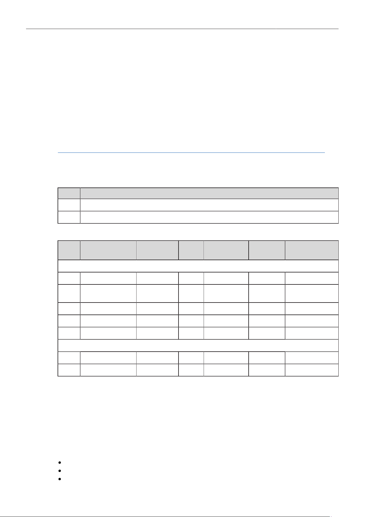
Appendix 131
Following Art. 3.1 b,
2014/30/EU:
EN 301 489-1 V2.1.1
EN 301 489-17 V3.1.1
EN 55032:2015
EN 55035:2017
Art. 3.2 EN 300 328 V2.1.1
Essential Requirements regarding No 2:
EN 50581:2012
To evaluate the respective information, we used:
http://ec.europa.eu/growth/single-market/european-standards/harmonised-standards/index_en.htm
Year of affixed CE-marking: 2019
APPENDIX I - List of Primes
Item Model Name
1 ARRI Signature Primes with Lens Data System 2 with focal lenght 18-280 mm
2 PL-to-LPL Adapter + ARRI Lenses with Lens Data System 1
APPENDIX II - List of Antennas
Item Manufacturer Model Name Gain
(dBi)
Radiation
Pattern
Type Connector
For ECS White Radio RF Module EMIP400s:
1 Nearson S131AM-2450S 2.0 Omni-directional Dipole Reverse SMA
2 Proant 333 (Ex-it 2400
Foldable)
2.0 Omni-directional Dipole Reverse SMA
3 Radial/Larsen R380.500.125 2.0 Omni-directional Dipole Reverse SMA
4 Wanshih WSS002 2.0 Omni-directional Dipole Reverse SMA
5 Taoglas GW26.0151 1.8 Omni-directional Monopole Reverse SMA
For WiFi 2.4 GHz RF Module ST60-2230C:
6 Radial R380.500.150 0.0 Omni-directional Monopole Reverse SMA
7 LAIRD LSR/001-009 2.0 Omni-directional Dipole Reverse SMA
FCC Compliance Statement
Class B Statement: This equipment has been tested and found to comply with the limits for a Class B
digital device, pursuant to part 15 of the FCC Rules. These limits are designed to provide reasonable
protection against harmful interference in a residential installation. This equipment generates, uses and
can radiate radio frequency energy and, if not installed and used in accordance with the instructions,
may cause harmful interference to radio communications. However, there is no guarantee that
interference will not occur in a particular installation. If this equipment does cause harmful interference
to radio or television reception, which can be determined by turning the equipment off and on, the user
is encouraged to try to correct the interference by one or more of the following measures:
Reorient or relocate the receiving antenna.
Increase the separation between the equipment and receiver.
Connect the equipment into an outlet on a circuit different from that to which the receiver is
connected.
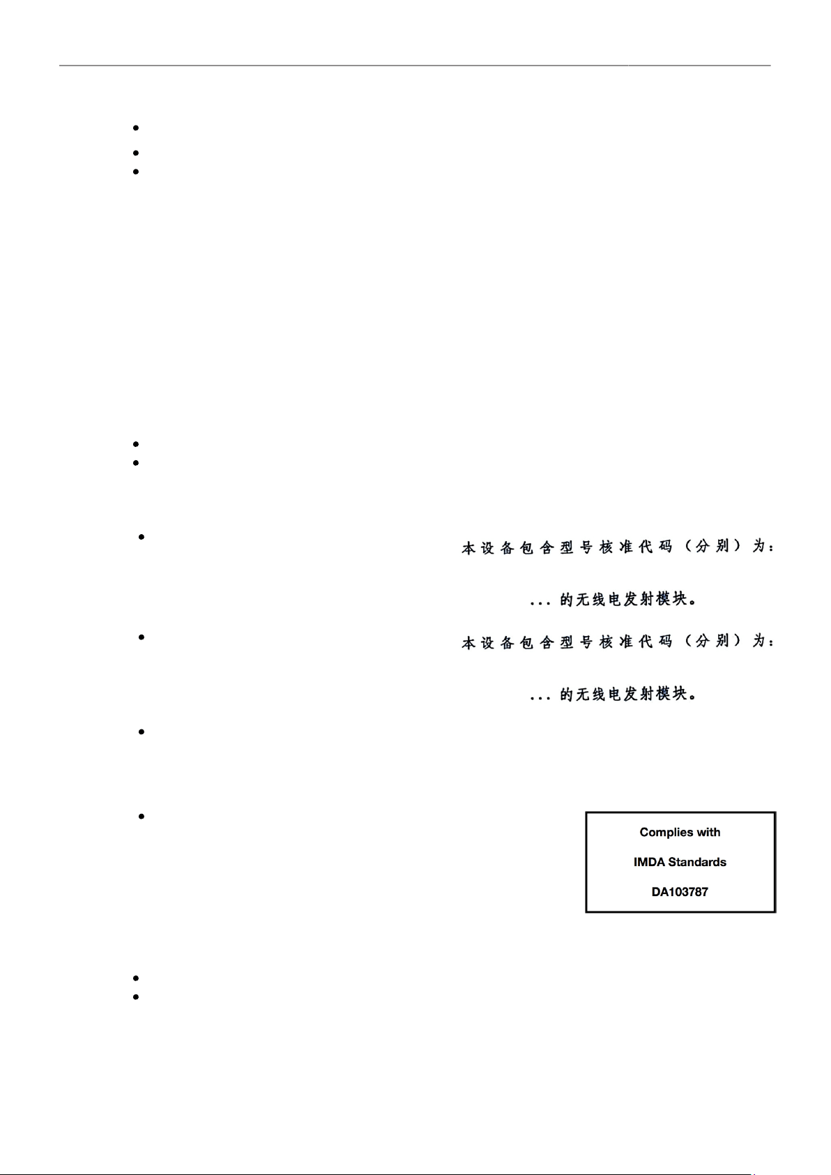
Appendix 132
Consult the dealer or an experienced radio/TV technician for help.
WIFI: FCC ID: SQG-60SIPT
ECS transceiver module: FCC ID: Y7N-EMIP400
Industry Canada Compliance Statement
Complies with the Canadian ICES-003 Class B specifications.
Cet appareil numérique de la Classe B est conforme à la norme NMB-003 du Canada.
This device contains licence-exempt transmitter(s)/receiver(s) that comply with Innovation, Science and
Economic Development Canada’s licence-exempt RSS(s). Operation is subject to the following two
conditions:This device may not cause interference. This device must accept any interference, including
interference that may cause undesired operation of the device.
L’émetteur/récepteur exempt de licence contenu dans le présent appareil est conforme aux CNR
d’Innovation, Sciences et Développement économique Canada applicables aux appareils radio
exempts de licence. L’exploitation est autorisée aux deux conditions suivantes :L’appareil ne doit pas
produire de brouillage;L’appareil doit accepter tout brouillage radioélectrique subi, même si le brouillage
est susceptible d’en compromettre le fonctionnement.
WIFI: IC ID: 3147A-602230C
ECS transceiver module: IC ID: 9482A-EMIP400
China
ECS Transceiver Module:
CMIIT ID: 2017DJ7863 (M)
WiFi Module:
CMIIT ID: 2017AJ7897 (M)
ALEXA Mini LF:
Pending
Singapore
Dealer's License No: DA103787
Registration valid until 31. August 2024 for ALEXA Mini LF
(EMIP400s & LAIRD ST60-2230C)
India WPC Compliance Statement
WiFi: Pending
ECS transceiver module: ETH-1385/2018/ERLO
Appendix 133
South Korea
ALEXA Mini LF: Certification No: R-R-ARg-ALEXA_Mini_LF - Pending
ECS Transceiver Module: Certification No: R-CRM-ARg-EMIP400
WiFi Module: Certification No: MSIP-CRM-LAI-60-2230C
Japan
ECS Transceiver Module EMIP400: 020-180030
WiFi Module: 003-170091
United Arab Emirates
Wireless video devices: Dealer No: DA68290/17
(Registration valid until: 28th August, 2022; brand registration: 5 years)
ALEXA Mini LF: registered No: ER74494/19
Australia and New Zealand
ALEXA Mini LF
R-NZ
Philippines
Pending
Egypt
Pending

Appendix 134
South Africa
Pending
Taiwan
Pending
28.5 Dimensional Drawings
Dimensional drawings are attached at the end of this document. They are also available for download
on the ARRI website.
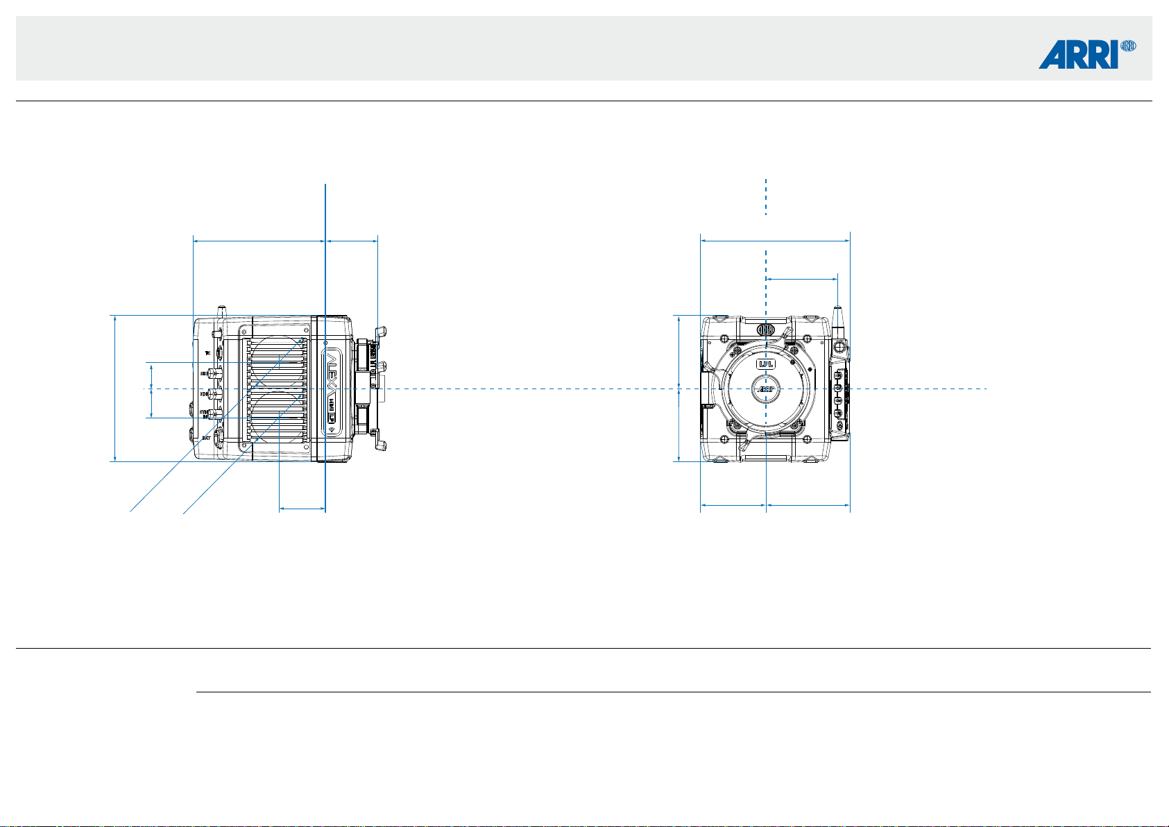
Technical Data are subject to change without notice.CAMERA DIMENSIONS – Version 2019-07
ALEXA Mini LF
ALEXA Mini LF Length Width Height Weight
Body + LPL mount
MVF-2
188 mm - 7.4” 143 mm - 5.6” 140 mm - 5.5” ~2.6 kg / ~5.7 lbs
800 g
Camera Right
Image Plane
Camera Front
Optical Center
Optical Center
140 mm
5.5”
25.4 mm
1.0”
28 mm
1.10”
70 mm
2.75”
70 mm
2.75”
142.92 mm
5.63”
68.65 mm
2.70”
62.42 mm
2.46”
80.5 mm
3.17”
129.9 mm
5.11”
Ø 51 mm
Ø 2.0”
Ø 51 mm
Ø 2.0”
49,45 mm
1.95”
45.2 mm
1.77”
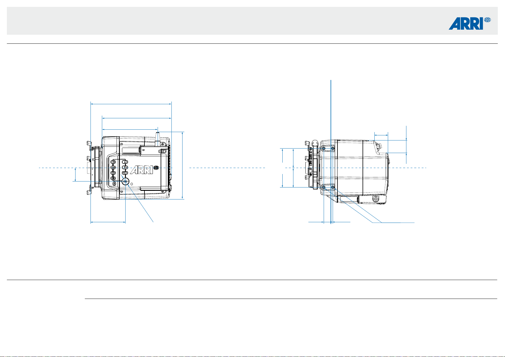
Technical Data are subject to change without notice.CAMERA DIMENSIONS – Version 2019-07
ALEXA Mini LF
ALEXA Mini LF Length Width Height Weight
Body + LPL mount
MVF-2
188 mm - 7.4” 143 mm - 5.6” 140 mm - 5.5” ~2.6 kg / ~5.7 lbs
800 g
M4 (8x) 4.4 mm deep
Camera Top
Image Plane
Camera Left
Optical Center
153.72 mm
6.05”
148.35 mm
5.84”
16 mm
0.63”
4 mm
0.16”
43 mm
1.69”
28.96 mm
1.14”
28.33 mm
1.11”
43 mm
1.69”
(mount contact surface to camera back)
179.28 mm
7.06”
77.3 mm
3.04”
Ø 15.4 mm
Ø 0.61”
30 mm
1.18”
149.5 mm
5.89”
86 mm
3.38”