

917.259950
Western Auto
Operation and Service Instructions
Wizard Lawn Tractor
Stock Number
93-7159-2
Model Number
AYP7159A69
Factory Number
AYP7159A69
_ This product has a iow em!ssion engine which oper_ differ-
ently from previously built engines: Before you start the engine;
read and understand this Owner's Manual.
Thank you for purchasing an American-built product.
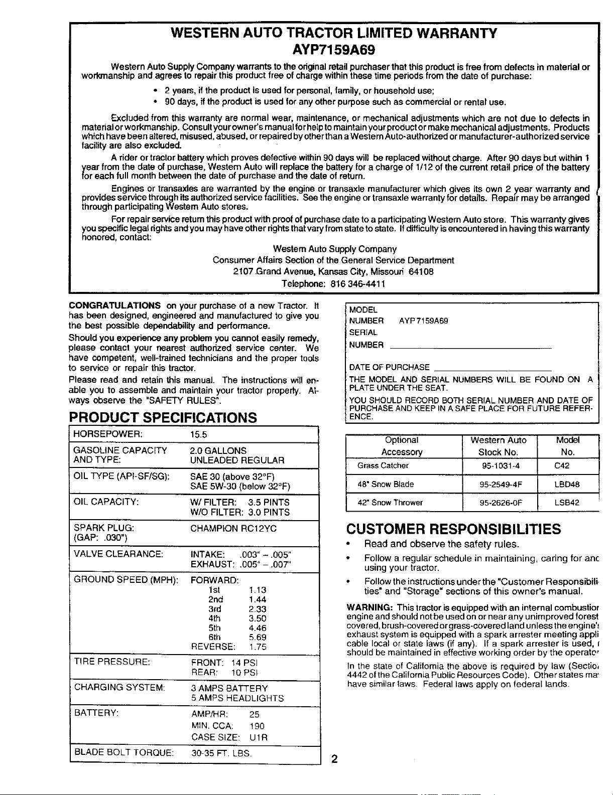
WESTERN AUTO TRACTOR LIMITED WARRANTY
AYP7159A69
Western Auto Supply Company warrants to the originalretail purchaser that this product isfree from defects in material or
workmanship and agrees to repair this product free ofcharge within these time periods from the date of purchase:
• 2 years, ifthe product is used for personal, family, or household use;
• 90 days, if the product is used for any other purpose such as commercial or rental use.
Excluded from this warranty are normal wear, maintenance, or mechanical adjustments which are not due to defects in
material orworkmanship. Consultyour owner's manual for hbiptomaintainyour productor makemechanical adjustments. Products
whichhave been altered, misused,abused, or repaired by otherthana Western Auto-authorized or manufacturer-authorized service
facility are also excluded.
A rider or tractor battery which proves defective within 90 days will be replaced without charge. After 90 days but within 1
_,oearfrom the date of purchase, Western Auto will replace the battery for a charge of 1/12 of the current retail price of the battery
r each full month between the date of purchase and the date of return.
Engines or transaxles are warranted by the engine or transaxle manufacturer which gives its own 2 year warranty and
provides service through its authorized service facilities. See the engine or transaxle warranty for dataiis. Repair may be arranged
through padicipating Western Auto stores.
For repair service returnthis product with proofof purchasedate toa padicipating Westem Auto store. This warranty gives
_ou specific legal rightsand you may have other rightsthat varyfrom stateto state. Ifdifficulty isencountered in having thiswarranty
onored, contact:
Westam Auto Supply Company
Consumer Affairs Section of the General Service Department
2107 Grand Avenue, Kansas City, Missouri 64108
Telephone: 816 346-4411
CONGRATULATIONS on your purchase of a new Tractor. It
has been designed, engineered and manufactured to give you
the best possible dependability and performance.
Should you experience any problem you cannot easily remedy,
please contact your nearest authorized service center. We
have competent, well-trained technicians and the proper tools
to service or repair this tractor.
Please read and retain this manual. The instructions will en-
able you to assemble and maintain your tractor properly. At-
ways observe the "SAFETY RULES".
PRODUCT SPECIFICATIONS
HORSEPOWER: 15.5
GASOLINE CAPACITY 2.0 GALLONS
AND TYPE: UNLEADED REGULAR
OIL TYPE (API-SF/SG): SAE 30 (above 32°F)
SAE 5W-30 (below 32°F)
OIL CAPACITY: W/FILTER: 3.5 PINTS
W/O FILTER: 3.0 PINTS
SPARK PLUG: CHAMPION RC12YC
3AP: .030")
VALVE CLEARANCE: INTAKE: .003" - .005"
EXHAUST: .605" - .007"
GROUND SPEED (MPH): FORWARD:
1st 1.13
2nd 1.44
3rd 2.33
4th 3.50
5th 4.46
6th 5.69
REVERSE: 1.75
TIRE PRESSURE: FRONT: 14 PSI
REAR: 10 PSI
CHARGING SYSTEM: 3 AMPS BATTERY
5 AMPS HEADLIGHTS
BATTERY: AMP/HR: 25
MIN. CCA: 190
CASE SIZE: U1R
BLADE BOLT TORQUE: 30-35 FT. LBS.
MODEL
NUMBER AYP 7159A69
SERIAL
NUMBER
DATE OF PURCHASE
THE MODEL AND SERIAL NUMBERS WILL BE FOUND ON A
PLATE UNDER THE SEAT.
YOU SHOULD RECORD BOTH SERIAL NUMBER AND DATE OF
PURCHASE AND KEEP IN A SAFE PLACE FOR FUTURE REFER-
ENCE.
Optional Western Auto Model
Accessory Stock No. No.
Grass Catcher 95-1031-4 C42
48" Snow Blade 95-2549-4F LBD48
42" Snow Thrower 95-2626-0F LSB42
CUSTOMER RESPONSIBILITIES
Read and observe the safety rules.
Follow a regular schedule in maintaining, caring for anc
using your tractor.
Follow the instructions under the "Customer Responsibili.
ties" and "Storage" sections of this owner's manual.
WARNING: This tractor isequipped with an internal combustior
engine and should not be used on or near any unimproved forest
covered, brush-covered or grass-covered land unless the engine'_
exhaust system is equipped with a spark arrester meeting appii
cable local or state laws (if any). If a spark arrester is used, I
should be maintained in effective working order by the operate,
In the state of California the above is required by law (Sectio_
4442 of the California Public Resources Code). Other states ma'
have similar laws. Federal laws apply on federal lands.
2

SAFETY RULESSafe Operation Practices for Ride-On Mowers ,_
IMPORTANT: THIS CUTTING MACHINE IS CAPABLE OF AMPUTATING HANDS AND FEET AND THROWING OBJECTS.
FAILURE TO OBSERVE THE FOLLOWING SAFETY INSTRUCTIONS COULD RESULT IN SERIOUS INJURY OR DEATH.
I= GENERAL OPERATION
Read, understand, and follow all instructionsin the manual
and on the machine before starting.
Only allow responsible adults, who are familiar with the
instructions, to operate the machine.
Clear the area of objects such as rocks, toys, wire, etc.,
which could be picked up and thrown by the blade.
Be sure the area isclear of otherpeople before mowing. Stop
machine if anyone enters the area,
Never carry passengers.
Do notmow in reveree unless absolutely necessary. Always
look down and behind before and while backing.
Be aware ofthe mower discharge direction and do not point
it at anyone. Do not operate the mower without either the
entire grass catcher or the guard in place.
Slow down before turning.
Never leave a running machine unattended. Always turnoff
blades, set parking brake, stop engine, and remove keys
before dismounting.
Turn off blades when not mowing.
Stop engine before removing grass catcher or unclogging
chute.
Mow only in daylight or good artificial light.
Do not operate the machine while under the influence of
alcohol or drugs.
Watch for traffic when operating near or crossingroadways.
Use extra care when loading or unloading the machine into
a trailer or truck.
II. SLOPEOPERA_ON
Slopes are a major factor related to loss-of-control and
tipover accidents, which can result in severe injury or
death. All slopes require extra caution. If you cannot back
up the slope or ifyou feel uneasy on it, do not mow it.
DO:
Mow up and down slopes, not across.
Remove obstacles such as rocks, tree limbs, etc.
Watch for holes, ruts, or bumps. Uneven terrain could
overturn the machine. Ta/I grass can hide obstac/es.
Use slowsbeed. Choose a low gear so thatyou will nothave
to stop or shift while on the slope.
Follow the manufacturer's recommendations for wheel
weights or counterweights to improve stability.
Use extra care with grass catchers or other attachments.
These can change the stability of the machine.
Keep all movement on the slopes s/owand gradual. Do not
make sudden changes in speed or direction.
Avoid starting or stopping on a slope. If tires lose traction,
disengage the blades and proceed slowly straight downthe
slope.
DO NOT:
Do not turn on slopes unless necessary, and then, turn slowly
and gradually downhill, if possible.
Do not mow near drop-offs, ditches, or embankments. The
mower could suddenly turn over if a wheel is over the edge
of a cliff or ditch, or if an edge caves in.
Do not mow on wet grass. Reduced traction could cause
sliding.
Do not try to stabilize the machine by puttingyour foot on the
ground.
Do not use grass catcher on steep slopes.
IlL CHILDREN
Tragic accidents can occur if the operator is not alert to the
presence of children. Children are often attracted to the
machine and the mowing activity. Never assume that
children will remain where you last saw them.
• Keep childrenout ofthe mowing area and under the watchful
care ofanother responsible adult.
• Be alert and tum machine off if children enter the area.
Before and when backing, look behind and down for small
children.
Never carry children. They may tall off and be sedeusly
injured or interfere with safe machine operation.
Never allow children to operate the machine.
Use extra care when approaching blind comers, shrubs,
trees, or other objects that may obscure vision.
IV. SERVICE
Useextra care in handlinggasoline and other fuels. They are
flammable and vapors are explosive.
Use only an approved container.
Never remove gas cap or add fuel with the engine
running. Allow engine to cool before refueling. Do not
smoke.
Never refuel the machine indoors.
Never store the machine or fuel container inside where
there isan open flame, such as a water heater.
Never run a machine inside a closed area.
Keep nutsand bolts, especially blade attachment bolts, tight
and keep equipment in good condition.
Never tamper with safety devices. Check their proper
operation regulady.
Keep machinefree of grass, leaves, or other debris build-up.
Clean oil or fuel spillage. Allow machine to cool before
storing.
Stop and inspect the equipment if you strike an object.
Repair, if necessary, before restarting.
Never make adjustments or repairswith the engine running.
Grass catcher components are subject towear, damage, and
detedoration, which could expose moving parts or allow
objects to be thrown. Frequently check components and
replace withmanufacturer's recommended parts, when nec-
essary.
Mower blades are sharp and can cut. Wrap the blade(s) or
wear gloves, and use extra caution when servicing them.
Check brake operation frequently. Adjust and service as
required.
Lookfor this symbol to point out important
safety precautions. It means
CAUTION!!! BECOME ALERT!!! YOUR
SAFETY IS INVOLVED.
&
CAUTION: Always disconnect spark plug
wire and place wire where it cannot contact
spark plug in order to prevent accidental
starting when setting up, transporting,
adjusting or making repairs.
A WARNING
The engine exhaust from this product contains
chemicals known to the State of California to
cause cancer, birth defects, or other reproduc-
tive harm.
3

TABLE OF CONTENTS
SAFETY RULES ............................................................ 3
PRODUCT SPECIFICATIONS ...................................... 2
CUSTOMER RESPONSIBILITIES ..................... 2, 15-19
WARRANTY .................................................................. 2
ASSEMBLY ............................................................... 6-8
OPERATION ............................................................ 9-14
MAINTENANCE SCHEDULE ..................................... 15
SERVICE AND ADJUSTMENTS ........................... 21
STORAGE .................................................................
TROUBLESHOOTING ........................................... 2;
REPAIR PARTS - TRACTOR ................................ 3(
REPAIR PARTS - ENGINE .................................... 41
PARTS ORDERING/SERVICE ............... BACK CO_
INDEX
A
Adjustments:
Brake ............................................ 22
Carburetor .................................... 25
Mower
Front-To-Back ......................... 21
Side-To-Side ................. :......... 20
Throttle Control Cable .................. 25
Air Filter, Engine .................................. 18
Air Screen, Engine .............................. 18
Assembly ............................................ 6-8
B
Battery:
Charging ........................................ 7
Cleaning ....................................... 16
Starting with Weak Battery ........... 23
Storage ........................................ 26
Terminals ..................................... 16
Belt:
Motion Drive
Removal/Replacement ............ 22
Mower Belt(s)
Removal/Replacement ............ 21
Blade:
Sharpening ................................... 16
Replacement ................................ 16
Brake Adjustment ................................ 22
C
Carburetor Adjustment ........................ 25
Controls, Tractor ................................. 10
Customer Responsibilities .............. 15-19
Engine:
Air Filter .................................... 18
Air Screen ................................ 18
Cooling Fins ............................. 18
Engine Oil ........................... 12,17
Fuel Filter ................................. 19
Spark Plug(s) ........................... 19
Tractor:,
Battery ...................................... 16
Blade ........................................ 16
Lubrication Chart ...................... 15
Maintenance Schedule ............ 15
Tire Care .......................... 8,16,23
Transaxle ................................. 17
Cutting Height, Mower ......................... 11
E
Electrical:
interlOCks and Relays ................... 24
Schematic .................................... 29
Wiring Diagram ............................ 30
Engine:
Air Filter ........................................ 18
Air Screen .................................... 18
Cooling Fins ................................. 18
Oil Change ................................... 17
Oil Level ....................................... 12
Oil Type ................................... 12,17
Preparation .................................. 12
Repair Parts ............................ 48-53
Starting......................................... 13
Storage ........................................ 26
F
Filter:
Air Filter ........................................ 18
Fuel .............................................. 19
Fuel:
Type ............................................. 12
Storage ........................................ 26
Fuse .................................................... 24
H
Hood Removal/Installation .................. 24
L
Leveling Mower Deck .......................... 21
Lubrication:
Chart ............................................ 15
Engine .......................................... 17
M
Maintenance Schedule ....................... t5
Mower:
Adjustment, Front-to-Back ........... 21
Adjustment, Side-to-Side ............. 20
Blade Replacement ...................... 16
Blade Sharpening ........................ 16
Cutting Height .............................. 11
Installation .................................... 20
Operation ..................................... 12
Removal ....................................... 20
Mowing Tips ........................................ 14
Muffler ................................................. 19
Spark Attester ........................... 2,40
O
Oil:
Cold Weather Conditions ........ 12,t 7
Engine .......................................... 17
Storage ........................................ 26
Operation ......................................... 9-14
Operating Mower ................................ 12
Options:
Accessories ................................
Spark Arrester ........................... :
P
Parking Brake ................................. 1_
Parts Bag ..........................................
Pads, Replacement/Repair ............ 3_
Product Specifications .......................
R
Repair Parts ................................... 3
S
Safety Rules ......................................
Seat ...................................................
Service and Adjustments ............... 2
Carburetor ..................................
Fuse ...........................................
Hood Removal/Installation .........
Motion Ddve Belt
Removal/Replacement ..........
Mower Belt(s)
Removal/Replacement ..........
Mower Adjustment
Frant-to-Back .......................
Side-to*Side ..........................
Mower Removal/Installation ......
Tire Care .............................. 8,1
Slope Guide Sheet ...........................
Spark Plug(s) ...................................
Specifications ...................................
Starting the Engine ........................ 1
Steering Wheel .................................
Stopping the Tractor .........................
Storage .............................................
T
Throttle Control Cable Adjustment ..
Tires ............................................ 8,
Troubleshooting Chart .................... :
Transaxle ....................................... .
W
Warranty ..........................................
Wiring Diagram ...............................
Wiring Schematic ............................
4

CONTENTS OF HARDWARE PACK
Parts Bag contents shown full size
(1) Large F_at (1) Hex Belt
Washer 3/8-16 x 1
O
_(3) Tinnerman Clips
(1) Hex Bolt 5116-18 x 1-1/4
(1) Lockwasher 3/8
@
(1) Locknut 5/16-18
(1) Shoulder
Bolt 5/16-18
©
(1) Hex Bolt
1/2-13 x 1
(1) Lock Washer 1/2
(1) Washer 17/32 x 1-3/16 x 12 Gauge
(2) Weld Nuts #10 ,_
(2) Screws _. _ I
.0x5/8/ . Li!
(2) Lock L _ )(2) Washers
_,_1_ Washers _. / 3/16 x 3/4 x
#10 _ 16 Gauge
(2) Hex Bolts _" Y_L'_ (2) Hex
1/4-20 x 3/4 _ Nuts1/4-20
(2) Washers
' 9/32 x 5/8 (2) Lock
x 16 Gauge Washers 1/4
Parts packed separately in carton
0
Steering
Wheel
Manu_
Seat
Steering
Sleeve
Mulcher
Plate
i
Parts Bag
Parts bag contents not shown full size
_ /F_ (2)Washers 3/8
(2) Shoulder (_'_) __j x7/8x14 Gauge
Bolts \ _/.//(2) Gauge _ (2) Center-
Wheels _ lock Nuts
_j= Steering
Wheel
Adapter
(2) Latch Hook
Steering ::€ Assemblys
/ Wheel
Insert (2) Keys
i
Steering
Extension
Shaft
Slope Sheet
J
i
io
5

ASSEMBLY
Your new tractor has been assembled at the factory with exception of those parts left unassembled for shipping purposes.
To ensure safe and proper operation of your tractorall parts and hardware you assemble mustbe tightened securely. Use
the correct tools as necessary to insure proper tightness.
TOOLS REQUIRED FOR ASSEMBLY
A socket wrench set willmake assembly easier. Standard
wrench sizes are listed.
(1) 3/4" Socket w/drive rachet Utility knife
(2) 7116"wrenches Tire pressure gauge
(2) 1/2=wrenches
(1) 9116"wrench
When dght or left hand is mentioned in this manual, it
means when you are in the operating position (seated
behind the steering wheel).
TO REMOVETRACTOR FROM CARTON
UNPACK CARTON
• Remove all accessible loose parts and parts cartons
from carton (See page 5).
• Cut, from top to bottom, along lines on all four comers
of carton, and lay panels flat.
• Check for any additional loose parts or cartons and
remove.
BEFORE ROLUNG TRACTOR OFF SKID
A'I-rACH STEERING WHEEL (See Fig. 1)
PREASSEMBLE SLEEVE TO STEERING WHEEL (See
Fig. 1 Inset)
Install sleeve retainer clips, evenly spaced around
steering wheel hub, with formed tabs toward the out-
side of hub.
• Press or lightly tap retainer clips fully onto steering
wheel hub.
Press stee ring sleeve fully onto steedng wheel hub and
clips.
ASSEMBLE EXTENSION SHAFT
Slide extension shaft onto lower steering shaft. Align
mounting holes in extension and lower shalts and
install5/16 hex bolt and Iocknut. Tighten securely.
IMPORTANT: TIGHTEN BOLT AND NUT SECURELY TO
18-22 FT. LBS TORQUE.
INSTALL STEERING WHEEL
Position front wheels ofthe tractor so they are pointing
straight forward.
Slide steering wheel adapter onto steering shaft exten-
sion.
Position steering wheel and sleeve assembly so cross
bars are horizontal (left to right) and slide onto adapter.
Assemble large flat washer, 3/8 lock washer, 3/8 hex
bolt and tighten securely.
Snap steering wheel insert into center of steering
wheel.
Remove protective plastic from tractor hood and grill.
IMPORTANT: CHECK FOR AND REMOVE ANY STAPLES
IN SKID THAT MAY PUNCTURE TIRES WHERE TRACTOR
IS TO ROLL OFF SKID,
STEERING ""-.-_./,
WHEEL 1
_' i "_,""-INSERT
3/8 HEX BOLT
3/8 LOCK WASHER
@1:------_ LARGE FLAT
WASHER
,/
J
;TEERING
SLEEVE
ADAPTER
I EXTENSION SHAFT
5/16 HEX BOLT
6
FIG. 1
TO ROLL TRACTOR OFF SKID (See Opera-
tion section for location and function of con-
trols)
Press liftlever plunger and raise attachment liftlever t¢
its highest position.
• Release parking brake by depressing ciutch/brak_
pedal.
• Place gearshift lever in neutral (N) position.
• Roll tractor backwards off skid.
• Remove banding holding discharge guard up agains
tractor.
CONNECT BATTERY (See Figs. 2 and 3)
&
CAUTION: Do not short battery termi-
nals. Before connecting battery, re-
move metal bracelets, wristwatch
bands, rings, etc.
Positive terminal must be connected
first to prevent sparking from acciden-
tal grounding.

ASSEMBLY
Remove cardboard packing from seat pan and lift seat
pan to raised position.
Open battery box door.
Remove terminal protective caps and discard.
If this battery is put into service after month and year
indicated on label (label located between terminals)
charge battery for minimum of one hour at 6-10 amps.
• First connect RED battery cable to positive (+)terminal
with hex bolt, flat washer, lock washer and hex nut as
shown. Tighten securely.
• Connect BLACK grounding cable to negative (-) termi-
nal with remaining hex bolt, flat washer, lock washer
and hex nut. Tighten securely.
• Close battery box door.
Open battery box door for:
• Inspection for secure connections (to tighten hard-
ware).
• Inspection for corrosion.
• Testing battery.
• Jumping (if required).
• Periodic charging.
POSITIVE
(RED) CABLE
DISCARD
TERMINAL
PROTECTIVE
CAPS
LOCK
HEX WASHER
NUT
FLAT
NASHER
HEX
BOLT
NEGATIVE
(BLACK) CABLE
FIG. 2
SEAT
PAN
BOX DOOR
FIG. 3
INSTALL SEAT (See Fig. 4)
Adjust seat before tightening adjustment bolt.
• Remove cardboard packing on seat pan.
• Place seat on seat pan and assemble shoulder bolt.
Assemble adjustment bolt, Iockwasher and flat washer
loosely. 'Do not tighten.
Tighten shoulder bolt securely.
• Lower seat intooperating position and sit on seat.
• Slide seat untila comfortable positionis reached which
allows you to press clutch/brake pedal all the way
down.
• Get off seat without moving its adjusted position.
• Raise seat and tighten adjustment bolt securely.
SEAT PAN
SHOULDER
BOLT
LARGE FLAT
WASHER
ADJUSTMENT LOCKWASHER
BOLT
FIG. 4
ASSEMBLE GAUGE WHEELS TO MOWER
DECK (See Fig. 5)
Assemble gauge wheels with tractor on a flat level surface.
• Adjust mower to desired cutting height (See 'q-O AD-
JUST MOWER CUFFING HEIGHT" in the Operation
section of this manual).
• With mower in desired height of cut position, gauge
wheels should be assembled so they are slightly off the
ground. Install gauge wheel in appropriate hole with
shoulder bolt, 3/8 washer, and 3/8-16 Iocknut and
tighten securely.
• Repeat for opposite side installing gauge wheel in
same adjustment hole.
GAUGE WHEEL
MOUN_NGBRACKET_._.
SHOULDER BOLT
FIG. 5
7
ASSEMBLY
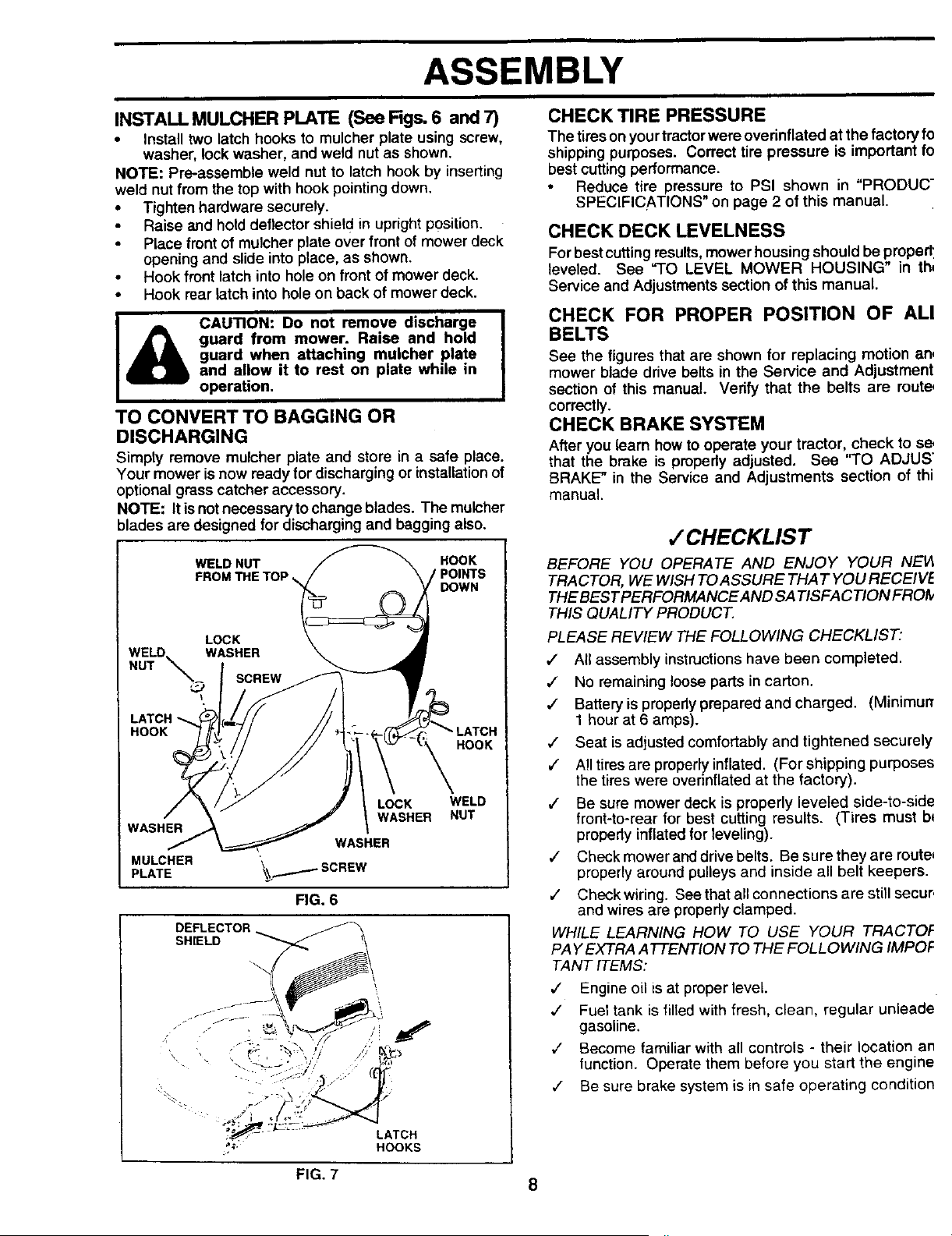
INSTALL MULCHER PLATE (See Figs. 6 and 7)
• Install two latch hooks to mulcher plate using screw,
washer, lock washer, and weld nut as shown,
NOTE: Pre-assemble weld nut to latch hook by inserting
weld nut from the top with hook pointingdown.
• Tighten hardware securely.
Raise and hold deflector shiel d in upright position.
Place front of mulcher plate over front of mower deck
opening and slide into place, as shown.
i Hookront'atch'nt°ho'eonfront°fmowerdeckI
Hook rear latch into holeon back of mower deck.
CAUTION: Do not remove discharge
guard from mower. Raise and hold
guard when attaching mulcher plate
and allow it to rest on plate while in
operation.
TO CONVERT TO BAGGING OR
DISCHARGING
Simply remove mulcher plate and store in a safe place.
Your mower isnow ready for discharging or installationof
optional grass catcher accessory.
NOTE: It is not necessary to change blades. The mulcher
blades are designed for discharging and bagging also.
WELD NUT HOOK
FROM THE TOP ,_, POINTS
DOWN
LOCK
WELD WASHER
NUT __ SCREW
LATCH
HOOK
HOOK
LOCK WELD
WASHER NUT
WASHER
WASHER
PLATEMULCHER _SCREW
FIG. 6
DEFLECTOR _
s.,E,D-7<
• .. ,\ "_.__.• j _,_"
-_:,_ - - LATCH
_;- HOOKS
CHECK TIRE PRESSURE
The tireson yourtractorwere overinflated at the factory fo
shippingpurposes. Correct tire pressure is important fo
best cutting performance.
Reduce tire pressure to PSI shown in "PRODUC"
SPECIFICATIONS" on page 2 of this manual.
CHECK DECK LEVELNESS
Forbestcuttingresults,mower housing should be propedl
leveled. See "TO LEVEL MOWER HOUSING" in th,
Service and Adjustmentssection of this manual.
CHECK FOR PROPER POSITION OF ALl
BELTS
See the figures that are shown for replacing motion an,
mower blade drive belts in the Service and Adjustment
section of this manual. Verify that the belts are route,
correctly.
CHECK BRAKE SYSTEM
After you learn how to operate your tractor, check to s_
that the brake is propedy adjusted. See =TO ADJUS"
BRAKE" in the Service and Adjustments section of thi
manual.
,f CHECKLIST
BEFORE YOU OPERATE AND ENJOY YOUR NEI4
TRACTOR, WE WISH TOASSURE THAT YOU RECEIVE
THE BEST PERFORMANCEAND SA TISFA CTION FROI9
THIS QUALITY PRODUCT.
PLEASE REVIEW THE FOLLOWING CHECKLIST:
1 All assembly instructions have been completed•
1 No remaining loose parts in carton.
,/ Batteryis propedyprepared and charged. (Minimur_
1 hour at 6 amps).
,/ Seat isadjusted comfortably and tightened securely
,f All tires are properly inflated• (For shipping purposes
the tires were overinflated at the factory).
,/ Be sure mower deck is properly leveled side-to-side
front-to-rear for best cutting results. (Tires must b*
propedy inflated for leveling).
,/ Check mower and drive belts. Be sure they are route_
properly around pulleys and inside all belt keepers•
,/ Check wiring. See that all connections are still secur,
and wires are propedy clamped•
WHILE LEARNING HOW TO USE YOUR TRACTOF
PAY EXTRA ATTENTION TO THE FOLLOWING/MPOF
TANT ITEMS:
,/ Engine oil is at proper level.
,/ Fuel tank is filled with fresh, clean, regular unleade
gasoline.
v" Become familiar with all controls - their location an
lunction. Operate them before you start the engine
¢ Be sure brake system is in safe operating condition
FIG. 7
8

OPERATION
These symbols may appear on yourtractor or in literaturesupplied with theproduct. Learn and understand their meaning.
BATTERY CAUTION OR REVERSE FORWARD FAST SLOW
WARNING
ENGINE ON ENGINE OFF OIL PRESSURE CLUTCH LIGHTS ON LIGHTS OFF
@
FUEL CHOKE MOWER HEIGHT DIFFERENTIAL PARKING BRAKE UNLOCKED
LOCK LOCKED
k R N H L
REVERSE NEUTRAL HIGH LOW
!
MOWER LIFT
ATTACHMENT
CLUTCH ENGAGED
ATTACHMENT
CLUTCH DISENGAGED
PARKING BRAKE
IGNITION
DANGER, KEEP HANDS AND FEET AWAY
HYDROSTATIC FREE WHEEL
(Hydro Models only)
9

OPERATION
KNOW YOUR TRACTOR
READ THIS OWNER'S MANUAL AND SAFETY RULES BEFORE OPERATING YOUR TRACTOI
Compare the illustrations withyour tractor to familiarize yourself with the locations of various controls and adjustments. Say
this manual for future reference.
THROTTLE AMMETER
CONTROL
LIGHT SWITCH
POSITION
LIFT LEVER CLUTCW
PLUNGER BRAKE
PEDAL
ATTACHMENT ATTACHMENT
LIFT LEVER CLUTCH LEVER
IGNITION
SWITCH
PARKING BRAKE
GEARSHIFT
LEVER
HEIGHT ADJUSTMENT KNOB
FIG. 8
Our tractors conform to the safety standards of the American National Standards Institute.
A'n'ACHMENT CLUTCH LEVER: Used to engage the
mower blades, or other attachments mounted to your
tractor.
LIGHT SWITCH: Turns the headlights on and off.
THROTTLE CONTROL: Used to control engine speed.
CLUTCH/BRAKE PEDAL: Used for declutching and brak-
ing the tractor and starting the engine,
PARKING BRAKE: Locks clutch/brake pedal into the
brake position.
GEARSHIFT LEVER: Selects the speed and direction of
tractor.
ATTACHMENT LIFT LEVER: Used to raise and lower tl
mower deck or other attachments mounted to your trach
LIFT LEVER PLUNGER: Used to release attachment
fever when changing itsposition.
IGNITION SWITCH: Used for starting and stopping t!
engine,
HEIGHT ADJUSTMENT KNOB: Used to adjustthe mow
height.
AMMETER: Indicates charging (+) or discharging (-)
battery.
10

OPERATION
The operation of any tractor can result in foreign objects thrown into the eyes, which can
result in severe eye damage. Always wear safety glasses or eye shields while operating
your tractor or performing any adjustments or repairs. We recommend a wide vision
safety mask over the spectacles or standard safety glasses.
HOW TO USE YOUR TRACTOR
TO SET PARKING BRAKE (See Fig. 9)
Depress clutch/brake pedal intofull"BRAKE" position
and hold.
Place parking brake lever in"ENGAGED" position and
release pressure from clutch/brake pedal. Pedal should
remain in"BRAKE" position. Make sure parking brake
will hold tractor secure.
THRO'R'LE ATTACHMENT CLUTCH
CONTROL SWITCH PULL-OUT TO "ENGAGE"
\ PUSH-IN TO .
"BRAKE"__
/ _ _ _ GEARSHIFT
CLUTCH/BRAKE PEDAL LEVER
"DRIVE" POSITION
FIG. 9
STOPPING (See Fig. 9)
MOWER BLADES -
• Move attachment clutch lever to "DISENGAGED" po-
sition.
GROUNODRIVE-
Depress clutch/brake pedal into full "BRAKE" position.
• Move gearshift lever to neutral (N) position.
ENGINE -
• Move throttle control to slow (.al.) position.
NOTE: Failure to move throttle control to slow (,,ab)
position and allowing engine to idle before stopping may
cause engine to "backfire".
Turn ignition key to "OFF" position and remove key.
Always remove key when leaving tractor to prevent
unauthorized use.
Never use choke to stop engine.
NOTE: Under certain conditions when tractor is standing
idle with the engine running, hot engine exhaust gases may
cause "browning" of grass. To eliminate th_s possibility,
always stop engine when stopping tractor on grass areas.
CAUTION: Always stop tractor com-
pletsly, as described above, before leav-
ing the operator's position; to empty
grass catcher, etc.
TO USE THROTTLE CONTROL (See Fig. 9)
Always operate engine at full throttle.
Operating engine at less than full throttle reduces the
battery charging rate.
• Full throttle offers the best bagging and mower perfor-
mance.
TO MOVE FORWARD AND BACKWARD
(See Fig. 9)
The directionand speed of movement iscontrolled bythe
gearshift lever.
Start tractor with clutch/brake pedal depressed and
gearshift lever in neutral (N) position.
• Move gearshift lever to desired position.
Slowlyrelease clutch/brake pedal to start movement.
IMPORTANT: BRING TRACTOR TO A COMPLETE STOP
BEFORE SHIFTING OR CHANGING GEARS. FAILURE
TO DO SO WILL SHORTEN THE USEFUL LIFE OF YOUR
TRANSAXLE.
TO ADJUST MOWER CU'I-I'ING HEIGHT
(See Fig. 8)
The cutting height is controlled by turning the height
adjustment knob in desired direction.
Turn knob clockwise (F_) to raise cutting height.
• Turn knob counterclockwise (P_,) to lower cutting
height.
The cutting height range is approximately 1-1/2" to 4". The
heights are measured from the ground to the blade tip with
the engine not running. These heights are approximate
and may vary depending upon soil conditions, height of
grass and types of grass being mowed.
The average lawn should be cut toapproximately 2-1/2
inches during the cool season and to over 3 inches
during hot months. For healthier and better looking
lawns, mow often and after moderate growth.
For best cutting performance, grass over 6 inches in
height should be mowed twice. Make the first cut
relatively high; the second to desired height.
11

OPERATION
TO TRANSPORT
TO OPERATE MOWER (See Fig. 10)
Your tractorisequipped with an operatorpresence sensing
switch. Any attempt by the operator toleave the seat with
the engine runningand the attachment clutchengaged will
shut off the engine.
Select desired height ofcut.
Lower mower with attachment liftcontrol.
• Stad mower blades by engaging attachment clutch
control.
TO STOP MOWER BLADES - disengage attachment
clutch control.
CAUTION: Do not operate the mower
without either the entire grass catcher,
on mowers so equipped, or the dis-
charge guard in place.
ATTACHMENT CLUTCH
SWITCH PULL*OUT TO
"ENGAGE"
PUSH-IN TO
"DISENGAGE"
FIG. 10
TO OPERATE ON HILLS
I
CAUTION: Do not drive up or down |
hills with slopes greater than 15° and
I
do not drive across any slope.
Choose the slowest speed before starting up or down
hills.
Avoid stopping or changing speed on hills.
If slowing is necessary, move throttle control lever to
slower position,
If stepping is absolutely necessary, push clutch/brake
pedal quickly to brake position and engage parking
brake.
Move gearshift lever to 1st gear. Be sure you have
allowed room for tractor to roll slightly as you restart
movement.
To restart movement, slowly release parking brake and
clutch/brake pedal.
Make all tums slowly.
• Raise attachment lift to highest position with attacl
ment lift control.
• When pushing ortowing your tractor, be sure gearsh
lever is in neutral (N) position.
• Do not push or tow tractor at more than five (5) MPI-
NOTE: To protect hood from damage when transportir_
your tractor on a truck or a trailer, be sure hood is closed ar
securedtotractor. Useanappropriate meansof tying hoc
to tractor (rope, cord, etc.).
BEFORE STARTING THE ENGINE
CHECK ENGINE OIL LEVEL (See Fig. 15)
• Theengine in yourtractor has been shipped, from th
factory, already filled with summer weight oil.
• Check engine oilwith tractor on level ground.
• Remove oilfill cap/dipstickand wipe clean, reinsert th
dipstick and screw cap tight, wait for a few second:
remove and read oil level. If necessary, add oil un'
"FULL" mark on dipstick is reached. Do not overfill.
For cold weather operation you should change oil f(
easier starting (See "OIL VISCOSITY CHART" in th
Customer Responsibilities section of this manual).
To change engine oil, see the Customer Responsibil
ties section in this manual.
ADD GASOLINE
Fill fuel tank. Use fresh, clean, regular unleade
gasolinewitha minimum of87 octane. (Use of leade
gasolinewill increase carbon and lead oxide deposil
and reduce valve life). Do not mix oil with gasolim
Purchase fuel in quantitiesthat can be used within 3
days to assure fuel freshness.
IMPORTANT: WHEN OPERATING IN TEMPERATURE
BELOW 32°F(0°C), USE FRESH, CLEAN WINTER GRAD
GASOLINE TO HELP INSURE GOOD COLD WEATHE
STARTING.
WARNING: Experience indicates that alcohol blende
fuels (called gasohol or using ethanol or methanol) ca
attractmoisture whichleadsto separation and formation,
acids during storage. Acidic gas can damage the fu
system of an engine while in storage. To avoid engir
problems, the fuel system should be emptied before sto
age of 30 days or longer. Drain the gas tank, start tr
engine and let it run until the fuel lines and carburetor a
empty. Use fresh fuel next season. See Storage Instra
tions for additional information. Never use engine ,
carburetor cleaner products in the fuel tank or permane
damage may occur.
I & CAUTION: Fill to bottom of gas tank
filler neck. Do not overfill. Wipe off any
spilled oil or fuel. Do not store, spill or
use gasoline near an open flame.
12

OPERATION
TO START ENGINE (See Fig. 9)
When starting the engine for the firsttime or ifthe engine
has run out of fuel, it willtake extra cranking time to move
fuel from the tank to the engine.
Depress clutch/brake pedal and set parking brake.
• Place gear shift lever in neutral (N) position.
• Move attachment clutch to "DISENGAGED" position.
Move throttle control to choke (N) position.
Note: Before starting, read the warm and cold starting
procedures below.
Insert key intoignition and turn keyclockwise to"START'
position and release key as soon as engine starts. Do
not run starter continuously for more than fifteen sec-
onds per minute. If the engine does not start after
several attempts, move throttle control to fast (,t_)
position, wait afew minutes and try again. Ifengine still
does not start, move the throttle control back to the
choke (l"J) position and retry.
WARM WEATHER STARTING (50° F and above)
• When engine starts, move thethrottle control tothe fast
(,_) position.
The attachments and ground ddve can now be used. If
the engine does not accept the load, restart the engine
and allow itto warm up for one minute using the choke
as described above.
COLD WEATHER STARTING ( 50° F and below)
• When engine starts, allow engine to run with the throttle
control in the choke (\1) position until the engine runs
roughly, then move thrott e contro to fast (,_) position.
This may require an engine warm-up period from
several seconds to several minutes, depending on the
temperature.
• The attachments can also be used during the engine
warm-up period.
NOTE: If at a high altitude (above 3000 feet) or in cold
temperatures (below 32 F) the carburetor fuel mixture may
need to be adjusted for best engine performance. See 'q'O
ADJUST CARBURETOR" in the Service and Adjustments
section of this manual.
MOWING TIPS
• Tire chainscannot be used when the mower housing is
attached to tractor.
• Mower should be properly leveled for best mowing
performance. See "TO LEVEL MOWER HOUSING" in
the Service and Adjustments section of this manual.
• The left hand side of mower should be used for trim-
ming.
• Drive so that clippings are discharged onto the area
that has been cut. Have the cut area to the right of the
machine. This will result in a more even distribution of
clippings and more uniform cutting.
• When mowing large areas, startby turning to the dght
so that clippings will discharge away from shrubs,
fences, ddveways, etc. After one ortwo rounds, mow
in the opposite direction making left hand turns until
finished (See Fig. 11).
If grass is extremely tall, it should be mowed twice to
reduce load and possible fire hazard from dded clip-
pings. Make first cut relatively high; the second to the
desired height.
• Do not mow grass when it is wet. Wet grass will plug
mower and leave undesirable clumps. Allow grassto
dry before mowing.
Always operate engine at full throttle when mowing to
assure better mowing performance and proper dis-
charge of material. Regulate ground speed by select-
ing a low enough gear to give the mower cutting
performance as well as the quality of cut desired.
When operating attachments, select a ground speed
that willsuit the terrain and give best performance of
the attachment being used.
FIG, 11
13
OPERATION
MULCHING MOWING TIPS
IMPORTANT: FOR BEST PERFORMANCE, KEEP
MOWER HOUSING FREE OF BUILT-UP GRASS AND
TRASH. CLEAN AFTER EACH USE.
The special mulching blade will recut the grass clip-
pings many times and reduce them in size so that as
they fall onto the lawn they will-disperse into the grass
and not be noticed. Also, the mulched grass will
biodegrade quickly to provide nutrients for the lawn.
Always mulch with your highest engine (blade) speed
as this will provide the best recutting action of the
blades.
• Avoid cuttingyour lawn when itiswet. Wet grass tends
to form clumpsand interfereswith themulching action.
The besttime to mow your lawn isthe eady afternoon.
At thistime the grass has ddedand the newly cut area
will not be exposed to the direct sun.
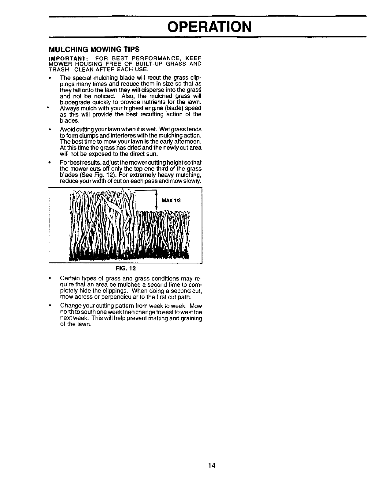
• For best results,adjustthemower cuttingheightsothat
the mower cuts off only the top one-third of the grass
blades (See Fig. 12). For extremely heavy mulching,
reduceyourwidthofcuton each passand mow slowly.
MAX 1/3
FIG. 12
Certain types of grass and grass conditions may re-
quire that an area be mulched a second time to com-
pletely hide the clippings. When doing a second cut,
mow across or perpendicular to the first cut path.
Change your cutting pattern from week to week. Mow
north to south one week then change toeast to west the
next week. This will help prevent matting and graining
of the lawn.
14

CUSTOMER RESPONSIBILITIES
FILL IN DATES j_'_._ _ _..>'__-.t_'_ ,_,_; A._' ,q.'< ,q._ _
AS YOU COMPLETE _/_._0_ __ .......
REGULARSERVICE _,1_ Y _ _.."_/¢'_ _.'_.:/_,_" SERVICE DATES
Check Brake Operation _1_ _1
Check Tire Pressure
T Check for Loose Fasteners I_ V'7 ¥4
R
Sharpen/Replace Mower Blades 11_4
LubricationChart !
T Check Battery Level/Recharge
Clean Battery and Terminals
R CheckTransaxleCooling If
AdjustBlade Belt(s) Tension VPs
AdjustMotion Drive Be_t(s)Tension Vts
Check Engine Oil Level V _ I
Change Engine Oil V' I_t_.3 I V #
Clean Air Filter V'2
E
N Clean Air Screen 1112
G InspectMuffler/Spark AtTester
I Replace Oil Filter(If equipped) Ik_1.2
N C_eanEngine Cooling Fins V'2
Replace Spark Plug II_ if
V'2Replace Air FilterPaper Cartridge
Replace Fuel Filter V'
1 - Change rn_e often when operating under a heavy load or in high ambient temperatun_.
2 - Service more often when operating in dirty or"dusty cond'_ons.
3 - If equ_ped with oilfilter, change oilevery 50 hours.
4 - Replace btades more often when mowing in sandy soil.
5 - If equipped with adjustable system.
6 - Not required if equipped with maintenance-free battery.
7 :Tighten front axle pivot boltto 35 ft.-Ibs, maximum.
Do not overdghten.
GENERAL RECOMMENDATIONS
LUBRICATION CHART
The warranty on thistractor does not cover itemsthat have (_
been subjected to operator abuse or negligence. To
receive full value from the warranty, operator must maintain
tractor as instructed in this manual.
Some adjustments will need to be made periodically to (_
properly maintain your tractor. BEARINGZERK
All adjustments in the Service and Adjustments section of
this manual should be checked at least once each season.
Once a year you should replace the spark plug, clean
or replace air filter, and check blades and belts for
wear. A new spark plug and clean air filter assure
proper air-fuel mixture and help your engine run better (_) CLUTCH
and last longer. PIVOT(S)
BEFORE EACH USE
Check engine oil level.
Check brake operation.
Check tire pressure.
Check for loose fasteners.
IMPORTANT: DO NOT OIL OR GREASE THE PIVOT POINTS
WHICH HAVE SPECIAL NYLON BEARINGS. VISCOUSLUBRI-
CANTS WILL ATTRACT DUST AND DIRT THAT WILL SHORTEN
THE LIFE OF THE SELF-LUBRICATING BEARINGS. IF YOU
FEEL THEY MUST BE LUBRICATED, USE ONLY A DRY. POW-
DERED GRAPHITE TYPE LUBRICANT SPARINGLY.
• FRONT WHEEL (_
BEARING ZERK
(D
PIVOTS
(_SAE 30 OR 10W30 MOTOR OIL
(_)GENERAL PURPOSE GREASE
(_REFER TO CUSTOMER RESPONSIBILITIES "ENGINE" SECTION
15

CUSTOMER RESPONSIBILITIES
TRACTOR TO SHARPEN BLADE (See Fig. 14)
Always observe safety rules when performing any mainte-
nance.
BRAKE OPERATION
If tractor requires more than six (6) feet stopping distance
at high speed in highest gear, then brake must be adjusted.
(See "TO ADJUST BRAKE" in the Service and Adjust-
ments section of this manua0.
TIRES
• Maintain proper air pressure in all tires (See =PROD-
UCT SPECIFICATIONS" on page 2 ofthis manual).
• Keep tires free of gasoline, oil,or insect controlchemi-
cals which can harm rubber.
• Avoid stumps, stones, deep ruts, sharp objects and
other hazards that may cause tire damage.
BLADE CARE
For best results mower blades must be kept sharp. Re-
place bent or damaged blades.
BLADE REMOVAL (See Fig. 13)
Raise mower to highest position to allow access to
blades.
Remove hex bolt, !ock washer and flat washer securing
blade.
• Installnew or resharpened blade with trailing edge up
towards deck as shown.
• Reassemble hex bolt, lock washer and flat washer in
exact order as shown.
Tighten bolt securely (30-35 Ft. Lbs. torque).
IMPORTANT: BLADE BOLT IS GRADE 8 HEATTREATED.
NOTE: We do not recommend sharpening blade - but ifyou
do, be sure the blade is balanced.
BLADE MANDREL
TRAILING EDGE
HEX BOLT
(GRADE 8)* _
*A GRADE 8 HEAT TREATED BOLT CAN BE
IDENTIFIED BY SIX LINES ON THE BOLT HEAD.
FIG. 13
Care should be taken to keep the blade balanced. /_
unbalanced blade will cause excessive vibration and evel
tual damage to mower and engine.
• The blade can be sharpened with a file or on a grindir
wheel. Do not attempt tosharpen while on the mowe
To check blade balance, you will need a 5/8" diamet_
steel bolt, pin, or a cone balancer. (When using a cot
balancer, follow the instructions supplied with b_
ancer).
• Slide blade on to an unthreaded portion ofthe steel Ix
or pin and hold the bolt or pin parallel with the groun,
If blade is balanced, it should remain in a horizont
position. If either end of the blade moves downwar
sharpen the heavy end until the blade is balanced.
NOTE: Do not use a nail for balancing blade. The lobes
the center hole may appear to be centered, but are not.
CENTER HOLE
5/8" BOLT
OR PIN
BLADE
FIG. 14
BATTERY
Your tractorhas a battery charging system which issuf
cient for normal use. However, periodic charging of tl"
battery with an automotive charger will extend its life.
• Keep battery and terminals clean.
Keep battery bolts tight.
• Keep small vent holes open.
Recharge at 6-10 amperes for 1 hour.
TO CLEAN BATTERY AND TERMINALS
Corrosion and dirt on the battery and terminals can cau:
the battery to "leak" power.
Open battery box door.
Disconnect BLACK battery cable first then RE
battery cable and remove battery from tractor.
Rinse the battery with plain water and dry.
Clean terminals and battery cable ends with w
brush until bright.
• Coat terminals with grease or petroleum jelly.
Reinstall battery (See "CONNECT BATTERY" in t
Assembly section of this manual).
16

CUSTOMER RESPONSIBILITIES
V-BELTS
Check V-belts for deterioration and wear after 100 hours of
operation and replace if necessary. The belts are not
adjustable. Replace belts if they begin to slip from wear.
TRANSAXLE COOLING
Keep transaxle free from build*up of dirt and chaff which
can restrict cooling.
ENGINE
LU BRICATION
Only use high quality detergent oil rated with API service
classification SF or SG. Select the oil's SAE viscosity grade
according to your expected operating temperature.
Change the oil after the first two hours of operation and
every 50 hours thereafter or at least once a year if the
tractor is not used for 50 hours in one year.
Check the crankcase oil level before starting the engine
and after each eight (8) hours of operation. Tighten oil fill
cap/dipstick securely each time you check the oil level.
ENGINE
LUBRICATION
Only use high quality detergent oil rated with API service
classification SF or SG. Select theoil'sSAE viscositygrade
according to your expected operating temperature.
SAE VISCOSITY GRADES
OF -20° (T' 30" 32 ° 40* 60 ° 80" IC_ °
OC .30 ° -20° -I0 ° 0 ° 10° 20" 30 ° 40 _
TEMPERATURE RANGE ANTICIPATED BEFORE NEXT OFL CHANGE
Air cooled engines run hotter tt_anautomotiveengme_, use of multl-wscoslty oils
10W-30, etc.) above 40°F (4oc) will result=nhk2.boilconsumption and possible
engine damage. Chod_ oillevel more fTedeentty us_g these types o o s.
°° SAE 30 oil, if used below 40_F(4°C), will resultin han:lstartingand possibleengine
bore damage due to inadequate lubrication.
NOTE: Although multi-viscosity oils (5W30, 10W30 etc.)
improve starting in cold weather, these multi-viscosity oils
will result in increased oil consumption when used above
32°F. Checkyour engine oil level morefrequentlyto avoid
possible engine damage from running low on oil.
Change the oil after the first two hours of operation and
every 50 hours thereafter or at least once a year if the
tractor is not used for 50 hours in one year.
Check the crankcase oil level before starting the engine
and after each eight (8) hours of operation. Tighten oil fill
cap/dipstick securely each time you check the oil level.
TO CHANGE ENGINE OIL (See Fig. 15 )
Determine temperature range expected before oil change.
All oilmust meet API service classification SF or SG.
Be sure tractor ison level surface.
• Oil willdrain more freely when warm.
Catch oilin a suitable container.
• Remove oil fill cap/dipstick. Be careful not to allow dirt
to enter the engine when changing oil.
• Remove drain plug.
• After oil has drained completely, replace oil drain plug
and tighten securely.
• Refill engine with oil through oi! fill dipstick tube. Pour
slowly. Do not overfill. For approximate capacity see
"PRODUCT SPECIFICATIONS" on page 3 of this
manual.
Use gauge on oilfill cap/dipstickforchecking level. Be
sure dipstick cap is tightened securely for accurate
reading. Keep oil at =FULL" line on dipstick.
OIL FILL
CAP/DIPSTICK
OIL DRAIN
PLUG
FIG. 15
17

CUSTOMER RESPONSIBILITIES
AIR FILTER (See Fig. 16)
Your engine will not run propedy using a dirty air filter.
Clean thefoam pre-cleaner after every 25 hours ofopera-
tion or every season. Service paper cartridge every 100
hours of operation or every season, whichever occurs first.
Service air cleaner more often under dusty conditions.
• Remove knob(s) and cover.
TO SERVICE PRE-CLEANER
• Slide foam pre-cleaner off cartridge.
• Wash it in liquid detergent and water.
• Squeeze itdry in a clean cloth.
• Saturate it in engine oil. Wrap it in clean, absorbent
cloth and squeeze to remove excess oil.
• If very dirty or damaged, replace pre-cleaner.
• Reinstall pre-cleaner over cartridge.
• Reinstall cover'and secure with knob(s).
TO SERVICE CARTRIDGE
• Remove cartddge nut.
Carefully remove cartridge to prevent debris from
entering carburetor. Clean base carefully to prevent
debris from entering carburetor.
Clean cartridge by tapping gently on flat surface. Ifvery
dirty or damaged, replace cartridge.
Reinstall cartridge, nut, precleaner, cover and secure
with knob(s).
IMPORTANT: PETROLEUM SOLVENTS, SUCH AS
KEROSENE, ARE NOT TO BE USED TO CLEAN THE
CARTRIDGE. THEY MAY CAUSE DETERIORATION OF
THE CARTRIDGE. DO NOT OIL CARTRIDGE. DO NOT
USE PRESSURIZED AIR TO CLEAN OR DRY
CARTRIDGE.
COVER-
KNOB
/ CARTRIDGE
COVERt _1_-- -_ NUT
PRE-CLEANER
_BASE
FIG. 16
CLEAN AIR SCREEN (See Fig. 17)
Air screen must be kept free of dirt and chaff to prever
engine damage from overheating. Clean with a wire brus
or compressed air to remove dirt and stubborn dried gut
fibers.
ENGINE COOLING FINS (See Fig. 17)
Remove any dust, dirt or oil from engine cooling fins t
prevent engine damage from overheating.
• Remove oilfill cap/dipstick.
• Remove hex boltsfromblower housing and lifthousin
offengine.
• Cover oi!fillopening to prevent entry of dirt.
• Use compressed air or stiff bristle brush tothorough
clean engine cooling fins.
• To reassemble, reverse above procedure.
HEX BLOWER HOUSING HEX
BOLTS BOLTS
AIR SCREEN
OILL FILL/
DIPSTICK
TUBE_
ENGINE COOLING FINS
SPARK
PLUG
FIG. 17
18

CUSTOMER RESPONSIBILITIES
MUFFLER
Inspect and replace corroded muffler and spark arrester (if
equipped) as it could create a fire hazard and/or damage.
SPARK PLUGS
Replace spark plugs at the beginning of each mowing
season or after every 100 hours of operation, whichever
occurs first. Spark ptug type and gap setting are shown in
"PRODUCT SPECIFICATIONS" on page 2 of this manual.
ENGINE OIL FILTER (See Fig. 18)
Replace the engine oil filter every season or every other oil
change if the tractor is used more than 100 hours in one
year.
Unscrew old filter by turning counterclockwise. Use a
suitable container to catch oil.
• Apply a thin coating of new engine oil to rubber gasket
on replacement oil filter.
• Install replacement oil filter by turning clockwise until
rubber gasket contacts mounting surface, then tighten
filter an additional 1/2 to 3/4 turn.
Fill crankcase with new oil (See "TO CHANGE EN-
GINE OIL" inthis section of this manual). For approxi-
mate capacity see "PRODUCT SPECIFICATIONS" on
page 3 of this manual.
Start engine and check for oil leaks. Correct any leaks
before placing engine into full operation.
IN-LINE FUEL FILTER (See Fig. 19)
The fuelfilter shouldbe replaced once each seasoo. If fuel
filterbecomes clogged, obstructingfuel flow tocarburetor,
replacement is required.
• With engine cool, remove filter and plug fuel line
sections.
• Place new fuel filter in position in fuel line with arrow
pointing towards carburetor.
Be sure there are no fuel line leaks and clamps are
properly positioned.
• Immediately wipe up any spilled gasoline.
CLAMP
FUEL
FILTER
FIG. 19
CLEANING
Clean engine, battery, seat, finish, etc. of all foreign
matter.
Keep finished surfaces and wheels free of all gasoline,
oil, etc.
Protect painted surfaces with automotive type wax.
We do not recommend using a garden hose to clean your
tractor unless the electrical system, muffler, air filter and
carburetor are covered to keep water out. Water in engine
can result in a shortened engine life.
FIG. 18
19
SERVICE AND ADJUSTMENTS
CAUTION: BEFORE PERFORMING ANY SERVICE OR ADJUSTMENTS:
Depress clutch/brake pedal fully and set parking brake.
Place gearshift lever in neutral (N) position.
Place attachment clutch in "DISENGAGED" position.
• Turn ignition key "OFF" and remove key.
• Make sure the blades and allmoving parts have completely stopped.
° Disconnect spark plug wire from spark plug and place wire where it cannot come in contact with
plug.
TRACTOR
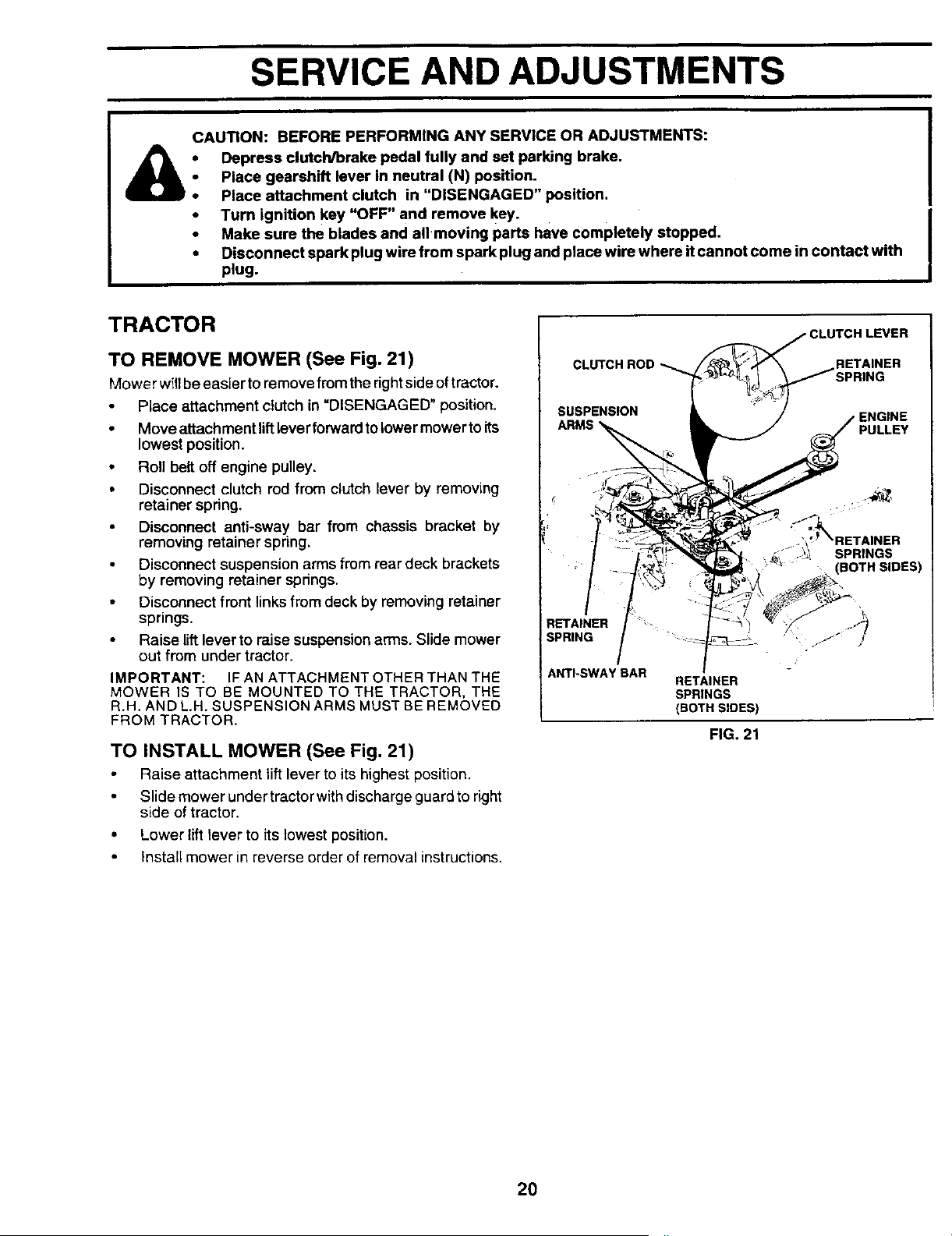
TO REMOVE MOWER (See Fig. 21)
Mower will be easier to remove from the right side of tractor.
Place attachment clutch in =DISENGAGED" position.
• Move attechment lift lever forward to lower mower to its
lowest position.
• Roll belt oft engine pulley,
• Disconnect clutch rod from clutch lever by removing
retainer spring.
Disconnect anti-sway bar from chassis bracket by
removing retainer spring.
Disconnect suspension arms from rear deck brackets
by removing retainer springs.
• Disconnect front links from deck by removing retainer
springs.
Raise lift lever to raise suspension arms. Slide mower
out from under tractor.
IMPORTANT: IF AN ATTACHMENT OTHER THAN THE
MOWER IS TO BE MOUNTED TO THE TRACTOR, THE
R.H, AND L.H. SUSPENSION ARMS MUST BE REMOVED
FROM TRACTOR,
TO INSTALL MOWER (See Fig. 21)
Raise attachment lift lever to its highest position.
Slide mower under tractor with discharge guard to right
side of tractor.
• Lower lift lever to its lowest position.
Install mower in reverse order of removal instructions.
CLUTCH ROD
H LEVER
SUSPENSION
ARMS
,ENGINE
PULLEY
RETAINER
SPRING
ANTI-SWAY BAR
RETAINER
SPRINGS
(BOTH SIDES
FIG. 21
2O

SERVICE AND ADJUSTMENTS
TO LEVEL MOWER HOUSING
Adjust the mower whiletractor isparked on level groundor
driveway. Make sure tires are properly inflated (See
"PRODUCT SPECIFICATIONS" on page 2 ofthismanual).
Iftires are over orundednflated, you willnot propedyadjust
your mower.
SIDE-TO-SIDE ADJUSTMENT (See Figs. 22 and 23) "
Raise mower to itshighest position.
• Atthe midpoint ofbothsidesofmower, measure height
from bottomedge ofmowerto ground. Distance'A" on
bothsides ofmower shouldbe the same or within1/4"
of each other.
If adjustment is necessary, make adjustment on one
side of mower only.
To raise one side of mower, tighten lift link adjustment
nut on that side.
• To lower one side of mower, loosen lift link adjustment
nut on that side.
NOTE: Three full turns of adjustment nut will change
mower height about 1/8".
Recheck measurements after adjusting.
Bo'n'OM EDGE BO'I-rOM EDGE
OFMOWERTO OFMOWERTO
GROUND GROUND
,-T I'"'}
FIG. 22
SUSPENSION ARM
LIFT LINK
ADJUSTMENT NUT
FIG. 23
FRONT-TO-BACK ADJUSTMENT (See Figs. 24 and 25)
IMPORTANT: DECK MUST BE LEVEL SIDE-TO-SIDE. IF
THE FOLLOWING FRONT-TO-BACK ADJUSTMENT IS
NECESSARY, BE SURE TO ADJUST BOTH FRONT LINKS
EQUALLY SO MOWER WILL STAY LEVEL SIDE-TO-
SIDE.
To obtain tile best cutting results, the mower housing
should be adjusted so that the front is approximately 1/4" to
3/4" lower than the rear when the mower is in its highest
position.
Check adjustment on right side of tractor. Measure dis-
tance "D" directly infront and behind the mandrel at bottom
edge of mower housing as shown.
• Before making any necessary adjustments, check that
both front links are equal in length. Both links should be
approximately 10-3/8".
If links are not equal in length, adjust one Ink to same
length as other link.
• To lower front of mower loosen nut "E" on both front
links an equal number of turns.
When distance "D" is 1/4" to 3/4" lower at front than
rear, tighten nuts "F" against trunnion on both front
links.
To raisefront of mower, loosen nut"F" from trunnion on
both front links. Tighten nut "E" on both front links an
equal number of turns.
When distance "D" is 1/4" to 3/4" lower at front than
rear,tighten nut"F" against trunnionon both front links.
Recheck side-to-side adjustment.
_:_*- _ o ,,i _ MANDREL
_j j
FIG. 24
BOTH FRONT UNKS MUST BE EQUAL IN LENGTH
NUT "F" _-_ NUT "E"
FRONT LINKS TRUNNION
21 FIG. 25
SERVICE AND ADJUSTMENTS
WITH PARKINGBRAKE "ENGAGED"
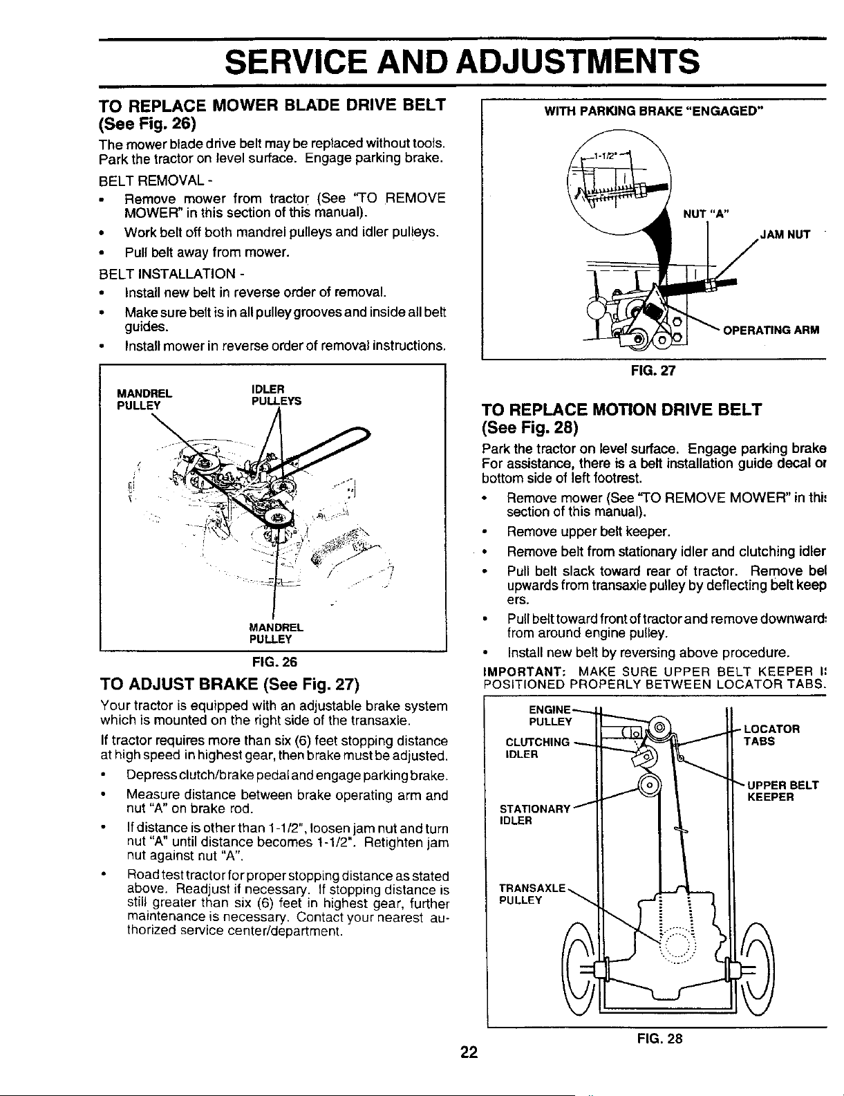
TO REPLACE MOWER BLADE DRIVE BELT
(See Fig. 26)
The mower blade drive belt may be replaced without tools.
Park the tractor on level surface. Engage parking brake.
BELT REMOVAL -
Remove mower from tractor (See "TO REMOVE
MOWER" in this section of this manual).
• Work belt off both mandrel pulleys and idler pulleys.
• Pull belt away from mower.
BELT INSTALLATION -
• Install new belt in reverse order of removal.
• Make sure belt is in all pulleygrooves and inside all belt
guides.
Install mower in reverse order of removal instructions.
MANDREL IDLER
PULLEY PULLEYS
/
MANDREL
PULLEY
FIG. 26
TO ADJUST BRAKE (See Fig. 27)
Your tractor isequipped with an adjustable brake system
which is mounted on the right side of the transaxle.
If tractor requires more than six (6) feet stopping distance
at high speed in highest gear, then brake must be adjusted.
Depress clutch/b rake pedal and engage parking brake.
Measure distance between brake operating arm and
nut "A" on brake rod.
If distance is other than 1-1/2", loosen jam nut and turn
nut "A" until distance becomes 1-1/2". Retighten jam
nut against nut "A".
Road test tractor for proper stopping distance as stated
above. Readjust if necessary. If stopping distance is
still greater than six (6) feet in highest gear, further
maintenance is necessary. Contact your nearest au-
thorized service center/department.
NUT "A"
JAM NUT
FIG. 27
TO REPLACE MOTION DRIVE BELT
(See Fig. 28)
Park the tractor on level surface. Engage parking brake
For assistance, there is a belt installation guide decal o_
bottom side of left footrest.
Remove mower (See "TO REMOVE MOWER" in thi=
section of this manual).
Remove upper belt keeper.
Remove belt from stationary idler and clutching idler
Pull belt slack toward rear of tractor. Remove bel
upwards from transaxle pulley by deflecting belt keep
ers.
• Pull belt toward front of tractorand remove downward:
from around engine pulley.
• Install new belt by reversing above procedure.
IMPORTANT; MAKE SURE UPPER BELT KEEPER I=
POSITIONED PROPERLY BETWEEN LOCATER TABS.
CLUTCHING _ /
IDLER f I!
LOCATOR
TABS
UPPER BELT
KEEPER
FIG. 28
22
SERVICE AND ADJUSTMENTS
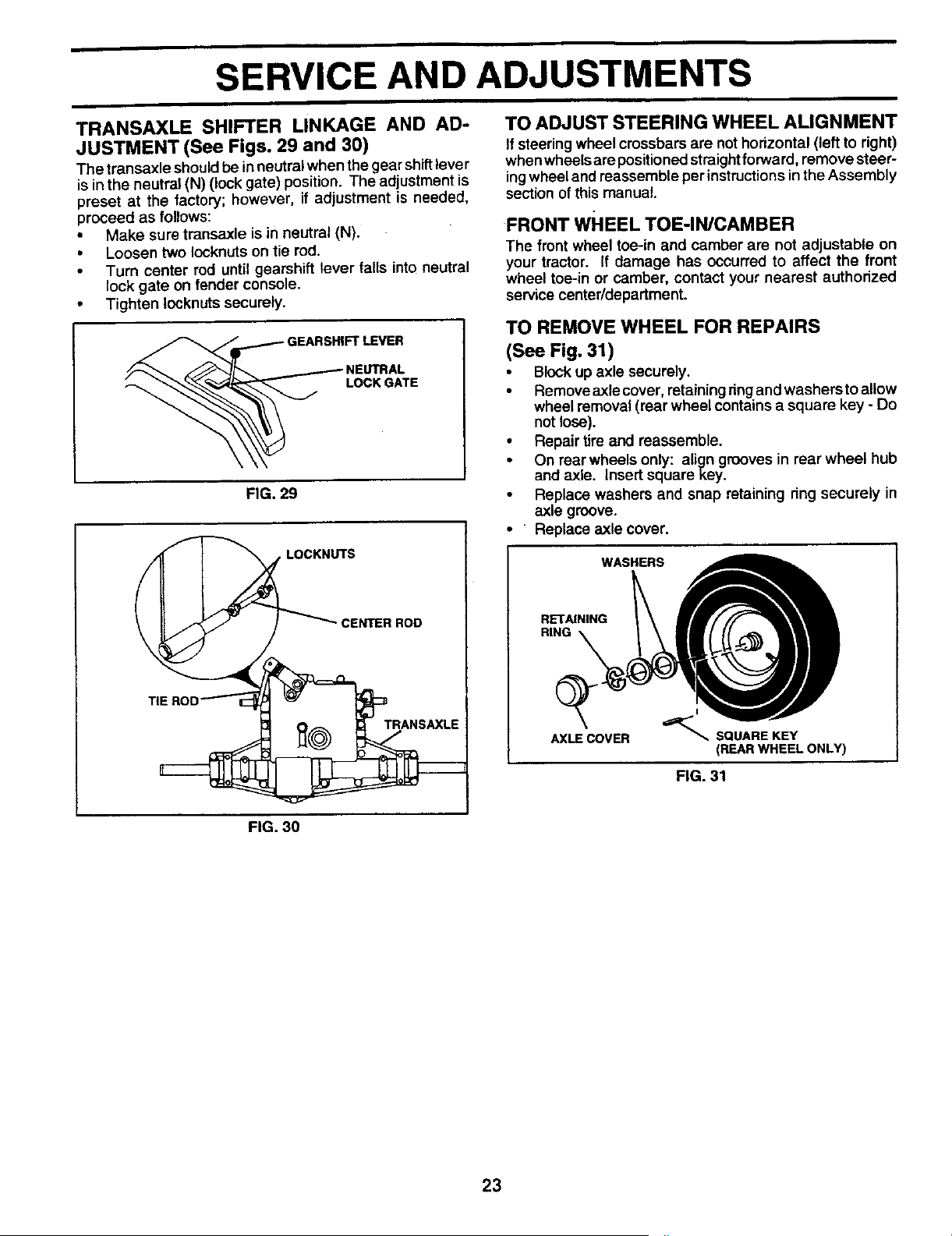
TRANSAXLE SHIFTER LINKAGE AND AD-
JUSTMENT (See Figs. 29 and 30)
The transaxle shouldbe inneutral when thegear shiftlever
isin the neutral (N) (lock gate) position. The adjustment is
preset at the factory; however, if adjustment is needed,
proceed as follows:
• Make sure transaxle is in neutral (N).
• Loosen two Iocknuts on tie rod.
• Turn center md until gearshift lever falls into neutral
lock gate on tender console.
• Tighten Iocknuts securely.
__ LOCK GATE
FIG. 29
TIE
, LOCKNUTS
CENTERROD
TO ADJUST STEERING WHEEL ALIGNMENT
Ifsteering wheel crossbars are not horizontal (left to right)
whenwheelsare positionedstraightforward, remove steer-
ingwheel and reassemble per instructionsinthe Assembly
section ofthis manual.
FRONT WHEEL TOE-IN/CAMBER
The front wheel toe-in and camber are not adjustable on
your tractor. If damage has occurred to affect the trent
wheel toe-in or camber, contact your nearest authorized
service center/department.
TO REMOVE WHEEL FOR REPAIRS
(See Fig. 31)
• Blockup axle securely,
Remove axlecover, retainingringandwashers to allow
wheel removal (rear wheel contains a square key - Do
not lose).
• Repair tire and reassemble.
• On rear wheels only: align grooves in rear wheel hub
and axle. Insert squarekey.
• Replace washers and snap retaining ring securely in
axle groove.
• Replace axle cover.
WASHERS
RETAINING
RING
AXLE COVER
(REAR WHEEL ONLY)
FIG. 31
FIG. 30
23

SERVICE AND ADJUSTMENTS
TO START ENGINE WITH A WEAK BA'n'ERY
(See Fig. 32)
CAUTION: Lead-acid batteries gener- I
ate explosive gases. Keep sparks, flame
I
and smoking materials away from bat-
teries. Always wear eye protection
when around batteries.
If your battery is too weak to startthe engine, itshould be
recharged. If "jumper cables" are used for emergency
starting, follow this procedure:
IMPORTANT: YOUR TRACTOR IS EQUIPPED WITH A 12
VOLT NEGATIVE GROUNDED SYSTEM. THE OTHER
VEHICLE MUST ALSO BE A 12 VOLT NEGATIVE
GROUNDED SYSTEM. DO NOT USE YOUR TRACTOR
BATTERY TO START OTHER VEHICLES.
TO ATFACH JUMPER CABLES -
• Connect each end of the RED cable tothe POSITIVE
(+) terminal of each battery, taking care not to short
against chassis.
• Connect one end of the BLACK cable to the NEGA-
TIVE (-) terminal of fully charged battery.
Connect the other end of the BLACK cable to good
CHASSIS GROUND, away from fuel tankand battery.
TO REMOVE CABLES, REVERSE ORDER -
BLACK cable first from chassis and then from the fully
charged battery.
RED cable last from both batteries.
POSITIVE TERMINAL NEGATIVE TERMINAL
CABLES
CHARGED
BATTERY
POSITIVE NEGATIVE
TERMINAL TERMINAL
TO REPLACE HEADLIGHT BULB
• Raise hood.
• Pull bulb holder out of the hole in the backside of the
grill•
Replace bulb in holder and push bulb holder securely
back into the hole in the backside of the grill.
• Close hood.
INTERLOCKS AND RELAYS
Loose or damaged widng may cause your tractor to run
poody, stop running, or prevent it from starting.
• Check wiring. See electrical wiring diagram in the
Repair Parts section of this manual.
TO REPLACE FUSE
Replace with 30 amp automotive-type plug-in fuse. The
fuse holder is located behind the dash.
TO REMOVE HOOD AND GRILL ASSEMBLY
(See Fig. 33)
• Raise hood.
• Unsnap headlight wire connector.
Stand infront oftractor. Grasp hood at sides, tilttoward
engine and tilt off of tractor.
• To replace, reverse above procedure.
HOOD
HEADLIGHT WIRE
CONNECTOR
FIG. 33
FIG. 32
24

SERVICE AND ADJUSTMENTS
ENGINE TO ADJUST CARBURETOR
TO ADJUST THROTTLE CONTROL CABLE
(See Fig. 34)
The throttle control has been preset at the factory and
adjustment should notbe necessary. Checkadjustmentas
described below before loosening cable. If adjustment is
necessary, proceed as follows:
• With engine not running, move throttle control lever
from slow (,_1_)to choke (\1) position. Slowly move
lever from choke (N) to fast (,_) post on.
• Checkthat holes"A" ingovernor control lever and hole
in governor plate line-up. If holes "A" are not aligned,
1oosen clamp screwand movethrottle cable until holes
are aligned. Tighten clamp screw securely.
GOVERNOR
CONTROL LEVER
GOVERNOR
CONTROLPLATE
HOLES "A"
CLAMP
SCREW
THROTTLE
CABLE
The carburetor has been preset at the factory and adjust-
ment should not be necessary. However, minor adjust-
ment may be required to compensate for differences in fuel,
temperature, altitude or load. If the carburetor does need
adjustment, see engine manual.
NOTE: The carburetor on this engine is low emission.
It is equipped with an idle fuel adjusting needle with
a limiter cap, which allows some adjustment within
the limits allowed by the cap. Do not attempt to
remove the limiter cap. The limiter cap cannot be
removed without breaking the adjusting needle.
IMPORTANT: NEVER TAMPER WITH THE ENGINE
GOVERNOR, WHICH IS FACTORY SET FOR PROPER
ENGINE SPEED. OVERSPEEDING THE ENGINE ABOVE
THE FACTORY HIGH SPEED SETTING CAN BE
DANGEROUS. IF YOU THINK THE ENGINE-GOVERNED
HIGH SPEED NEEDS ADJUSTING, CONTACT YOUR
NEAREST AUTHORIZED SERVICE CENTER/
DEPARTMENT, WHICH HAS PROPER EQUIPMENT AND
EXPERIENCE TO MAKE ANY NECESSARY
ADJUSTMENTS.
FIG. 34
25
STORAGE
ENGINE
Immediately prepare your tractor for storage at the end of
the season or if the tractor will not be used for 30 days or
more.
CAUTION: Never store the tractor with
gasoline in the tank inside a building
where fumes may reach an open flame "
or spark. Allow the engine to cool
before storing in any enclosure.
TRACTOR
Remove mower from tractor for winter storage. When
mower is to be stored for a period of time, clean it thor-
oughly, remove all dirt, grease, leaves, etc. Store in a
clean, dry area.
• Clean entire tractor (See "CLEANING" in the Customer
Responsibilities section of this manual).
• Inspect and replace belts, if necessary (See belt re-
placement instructions in the Service and Adjustments
section of this manual).
• Lubricate as shown in the Customer Responsibilities
section of this manual.
• Be sure that all nuts, bolts and screws are securely
fastened. Inspect moving parts fordamage, breakage
and wear. Replace if necessary.
• Touch up all rusted or chipped paint surfaces; sand
lightlybefore painting.
BATTERY
Fully charge the battery for storage.
After a period of time in storage, battery may require
recharging.
To help prevent corrosion and power leakage during
long periods of storage, battery cables should be
disconnected and battery cleaned thoroughly (see 'q'O
CLEAN BATTERY AND TERMINALS" in the Cus-
tomer Responsibilities section of this manual).
After cleaning, leave cables disconnected and place
cables where they cannot come in contact with battery
terminals.
Be sure battery drain tube is securely attached.
If battery is removed from tractor for storage, do not
store battery directly on concrete or damp surfaces.
FUELSYSTEM
IMPORTANT: IT IS IMPORTANT TO PREVENT G
DEPOSITS FROM FORMING IN ESSENTIAL FL
SYSTEM PARTS SUCH AS CARBURETOR, FUEL FILT
FUEL HOSE, OR TANK DURING STORAGE. AL
EXPERIENCE INDICATES THAT ALCOHOL BLEN[
FUELS (CALLED GASOHOL OR USING ETHANOL
METHANOL) CAN ATTRACT MOISTURE WHICH LEI
TO SEPARATION AND FORMATION OF ACIDS DUR
STORAGE. ACIDIC GAS CAN DAMAGE THE FL
SYSTEM OF AN ENGINE WHILE IN STORAGE.
Drain the fuel tank.
• Start the engine and let it run until the fuel lines
carburetor are empty.
• Never use engine or carburetor cleaner products in
fuel tank or permanent damage may occur.
• Use fresh fuel next season.
NOTE: Fuel stabilizer is an acceptable alternativG
minimizing the formation of fuel gum deposits during
age. Add stabilizer to gasoline in fuel tank or stor
container. Always follow the mix ratio found on stabil
container. Run engine at least 10 minutes after ado
stabilizer to allow the stabilizer to reach the carburetor.
not drain the gas tank and carburetor if using fuel stabili
ENGINE OIL
Drain oil (with engine warm) and replace with clean on!
oil. (See "ENGINE" in the Customer Responsibil
section of this manual).
CYLINDERS
Remove spark plug(s).
Pour one ounce of oil through spark plug hole(s)
cylinder(s).
Turn ignition keyto "START" position for a few sect
to distribute oil.
• Replace with new spark plug(s).
OTHER
Do not store gasoline from one season to anothe
• Replace your gasoline can if your can starts to
Rust and/or dirt in your gasoline will cause Droblc
If possible, store your tractor indoors and cover
give protection from dust and dirt.
Cover your tractor with a suitable protective cover
does not retain moisture. Do not use plastic. PI
cannot breathe which allows condensation to forrr
will cause your tractor to rust.
IMPORTANT: NEVER COVER TRACTOR WHILEEN(
AND EXHAUST AREAS ARE STILL WARM.
26

TROUBLESHOOTING POINTS
CAUSE CORRECTION
PROBLEM
Will not start
Hard to start
Engine will not turn over
Engine clicks but will not
start
Loss of power
Excessive vibration
1. Out of fuel
2. Engine not "CHOKED" properly.
3. Engine flooded.
4. Bad spark plug.
5. Dirty air filter.
6. Dirty fuel filter.
7. Water in fuel.
8. Loose or damaged widng.
9. Carburetor out of adjustment.
10. Engine valves out of ediustment.
1. Dirty air filter.
2. Bad spark plug.
3. Weak or dead battery.
4. D_rryfuel filter.
5. Stale or dirty fuel.
6. Loose or damaged wiring.
7+ Carburetor out of adjustment.
8. Engine valves out of adjustment.
1. Clutch/brake pedal not depmssod.
2. Attachment fflutch is engaged.
3. Weak or dead battery.
4. Btown fuse.
5. Corroded battery terminals.
6. Loose or damaged wiring:
7. Faulty igalfion switch.
8. Faulty solenoid or stader.
9. Faulty operator presence switch(es).
1. Weak or dead battery+
2. Corroded battery terminals.
3. Loose ordamaged widng.
4. Faulty solenoid or starter.
1. Cufflog too much grass/tea fast.
2. Throttle in"CHOKE" position.
3. Build-up of grass, leaves and trash under mower.
4. Dirty air filter.
5. Low oil level/dirty oil.
6. Faulty spark plug.
7. Dirty fuel filter.
8. Stale or dirty fuel.
9+ Waterin fuel.
10. Spark plug wire loose.
11. Dirty engine air screen/fins.
12. Dirty/clogged muffler.
13.
14.
10.
11.
12.
Loose or damaged winng. 13.
Carburetor out of adjustment. 14.
15 Engine valves out of adjustment.
t Worn. bent or loose blade.
2. Bent blade mandrel
3. Loose/damaged part(s)
1. F_IIfuel tank.
2. See "TO START ENGINE" in Operation section.
3. 'Wait several minutes before attempting to start.
4. Replace spark plug.
5. CIssNreplace air filter.
6. Replace fuel filter.
7. Drain fuel tank and carburetor, refill tank with fresh
gasoline and replace fuel fitter.
8. Check all wiring.
9. See "To Adjust Carburetor" in Service Adjustments
section.
10. Co,act an authedzed service center/dapartment.
1. Clean/replace air filter.
2. Replace spark plug.
3. Recharge or replace battery.
4, Replace fuel filter.
5. Drain fuel tank and refill with fresh gasoline.
6. Check all wiling.
7. Sea "To Adjust Carburetor" in Service Adjustments
sec_on.
8. Contact an authedzed service center/dapartmant.
1. Depress elutol'Vbrake pedal.
2. Disengage attachment clutch.
3. Recharge or replace battery.
4. Replace fuse.
5. Clean battery terminals.
6. Check all widng.
7. Check/replace ignition switch.
8. Check/replace solenoid or starter,
9. Contact an authedzod service center/department.
1. Recharge or replace battery,
2. Clean battery terminals.
3. Check all wiring.
4. Check/replace solenoid or starter.
1. Set in =Higher Cut" posi_on/reduce speed.
2. Adjust throttle control.
3. Clean underside of mower housing.
4. Clean/replace air filter.
5. Check oil level/change oil.
6. Clean and regap or change spark plug.
7. Replace fuel filter.
8. Drain fuel tank and refill with fresh gasoline.
9. Drain fuel tank and carburetor, refill tank with fresh
gasoline and replace fuel filter.
Connect and tighten spark plug wire.
Clean engine air screen/fins.
Clean/replace muffler.
Check all wiring.
See "To Adjust Carburetor" in Service Adjustments
section.
15. Contact an authorized service center/department.
1 Replace blade. Tighten blade bolt.
2. Replace blade mandrel.
3. Tighten loose part(s). Replace damaged parts.
27

TROUBLESHOOTING POINTS
PROBLEM CAUSE CORRECTION
Engine continues to run
when operator leaves seat
with attachment clutch
engaged
Poorcut-uneven
Mower blades will not
rotate
Poor grass discharge
Headlight(s) not working
(if so equipped)
Battery will not charge
Engine "backfires"
when turning engine
"OFW'
t. Faulty operator-safety presence controlsystem.
1. Worn, bent or loose blade.
2. Mower deck not level.
3. Buildup of grass, leaves, and trash under mower.
4. Bent blade mandrel.
5. Clogged mower deck vent holes from buildup of
grass, leaves, and trash around mandrels.
1. Obstruction in clutch mechanism.
2. Worn/damaged mower drive belt.
3. Frozen idler pulley.
4. Frozen blade mandrel.
1. Engine speed too slow.
2. Travel speed too fast.
3. Wet grass.
4. Mower deck not level.
5. Low/unevan tire air pressure.
6. Worn, bent or loose blade.
7. Buildup of grass, leaves and trash under mower.
8. Mower drive belt worn.
9. Blades improperly installed.
10. Improper blades used.
11. Clogged mower deck vent boles from buildup of
grass, leaves, and trash around mandrels.
1. Switch is "OFF'.
2. Bulb(s) burned out.
3. Faulty light switch.
4. Loose or damaged wiring.
5. Blown luse.
t. Bad battery cell(s).
2. Poor cable connections.
3. Faulty regulator (if so equipped).
4. Faulty alternator.
1. Engine throttle control not set at "SLOW"
position for 30 seconds before stopping engine.
1. Check widog, switches and connections. If not
corrected, contact an authorized service center/
department.
1. Replace blade. Tighten blade bolt.
2. Level mower deck.
3. Clean underside of mower housing.
4. Replace blade mandrel.
5. Clean around mandrels to open vent holes.
t. Remove obstruction.
2. Replace mower ddve belt.
3. Replace idler pulley.
4. Replace blade mandrel.
1. Place throttle control in "FAST" position.
2. Shift to slower speed.
3. Allow grass to dry before mowing.
4. Level mower deck.
5. Check tires for proper air pressure.
6. Replace/sharpen blade. Tighten blade bolt.
7. Clean undemide of mower housing.
8. Replace mower drive belt.
9. Reinstall blades sharp edge down.
10. Replace with blades listed in this manual.
11. Clean around mandrels to open vent holes.
1. Turn switch =ON".
2. Replace bulb(s).
3. Check]replace lightswitch.
4. Check wiring and connections.
5. Replace fuse.
1. Replace battery.
2. Check/clean all connections.
3. Replace regulator.
4. Replace alternator.
1. Move throttle control to "SLOW" position and allow
to idle for 30 seconds before stopping engine.
28

SCHEMATIC
TRACTOR - - MODEL NUMBER AYP7159A69
RED
BATTERY
ELACK
AMMETER
POSITION
OFF
RUN/LIGHT
RUN
START
G L,
IGNITION
RER
WHITE
FUSE 30 AMP.
CLUTCH / BRAKE
(PEDAL UP)
, I '
RED (_
I
I
I
SOLENOID
STARTER
SWITCH
rT--n n_n DE_3
IGNI_ON SWITCH
CIRCUIT
G+M+L
B+L
B÷L
B+L+S
L ..... J I
I
A"FI'ACHMENT I
CLUTCH
(CLUTCH OFF) I
SEAT SWITCH
(NOT OCCUPIED)
f I
I I
_1
GROUNDING
CONNECTOR
BLUE
RED
ORANGE
@
IGNITION _ SPARK O
/
UNIT PLUG
"MAKE"
NONE
A+ Y
NONE
NONE
B_CK
B_CK
I- I
I_ _1
AFTER FIRE SOLENOID 2s VOLTS AC MIN. @ 3600 RPM
{CHARGING SYSTEM DISCONNECTED)
CHARGING SYSTEM OUTPUT \ /
3 AMP DC @ 3600 RPM _
LIGHTING SYSTEM OUT]PUT ......... J
5 AMP AC @ 3600 RPM _t_ 14 VOLTS AC MIN @ 3600 RPM (LIGHTS OFF)
NON-REMOVABLE
CONNECTIONS
_a EADL BLAC K.K
IGHTS
NOTE
BROWN
YOUR TRACTOR IS EQUIPPED WITH
A SPECIAL ALTERNATOR SYSTEM.
THE LIGHTS ARE NOT CONNECTED
TO THE BATTERY, BUT HAVE THEIR
OWN ELECTRICAL SOURCE.
BECAUSE OF THIS, THE BRIGHTNESS
OF THE LIGHTS WILL CHANGE WITH
ENGINE SPEED. AT IDLE THE LIGHTS
WILL DIM. AS THE ENGINE IS
SPEEDED UP, THE LIGHTS WILL
BECOME THEIR BRIGHTEST.
REMOVABLE
CONNECTIONS
WIRING INSULATED CLIPS
NOTE: IF WIRING INSULATED
CLIPS WERE REMOVED FOR
SERVICING OF UNIT, THEY
SHOULD BE REPLACED TO
PROPERLY SECURE YOUR
WIRING
29
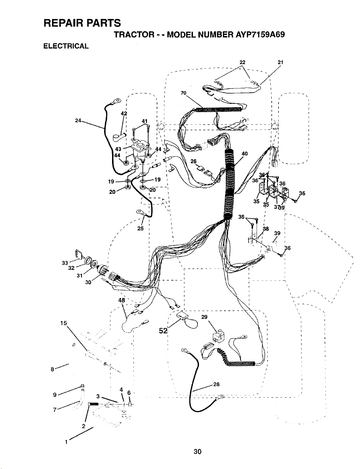
REPAIR PARTS
TRACTOR - - MODEL NUMBER AYP7159A69
ELECTRICAL
t
i I
4;Z r
41
7O
22 21
15
3O
36
35
\
/
/
/

REPAIR PARTS
TRACTOR -- MODEL NUMBER AYP7159A69
ELECTRICAL
•KEY PART
NO. NO. DESCRIPTION
1 146139
2 74760412
3 19091016
4 10040400
6 73220400
7 109238X
8 144940
9 109596X
15 147688
19 10090400
20 73350400
21 136850
22 4152J
24 4799J
25 146147
26 108824X
28 4207J
29 121305X
30 140301
31 124211X
32 141226
33 122147X
35 108236X
36 17021008
38 140336
39 109553X
40 151212
41 71110408
42 131563
43 145673
44 73640400
45 121433X
46 141940
70 141164
Battery 12 Volt 25 Amp w/acid
Bolt Hex Hd 1/4-20unc X 3/4
Washer 9/32 X 5/8 X 16 Ga
Washer Lock Hvy Helical 1/4
Nut Fin Hex 1/4-20 Unc
Tube Plastic 12"
Case Battery w/2 Holes w Bnty
Clamp Hose Olive
Fastener Snap In
Washer Lock 1/4
Nut Jam Hex 1/4-20 Unc
Harness Socket Light w/4152J
Bulb, Light # 1156
Cable Battery 6ga 11" Red
Cable Battery 6 Ga Red w/16 wire
Fuse 30 Amp Auto Green
Cable Ground 6ga 12"black
Switch Plunger Nc Gray
Switch Ign 4 Pos W/L P/L
Nut Ignition
Cover Sw Key
Key Ign Molded Generic
Bracket Switch Clutch
Screw Hex Tapping # 10-24 Unc x 1/2
Bracket Switch Interlock
Switch Interlock 4 Term
Harness Ign
Bolt Fin Hex 1/4-20uncx 1/2
Cover Terminal Red
Solenoid
Nut Keps BIk 1/4-20 Uric
Ammeter Rectangular 6 Amp
Protection Loop
Harness Eng P/L B&S 140HV Du HL
NOTE: All component dimensions given in U.S. inches
1 inch = 25.4 mm
31
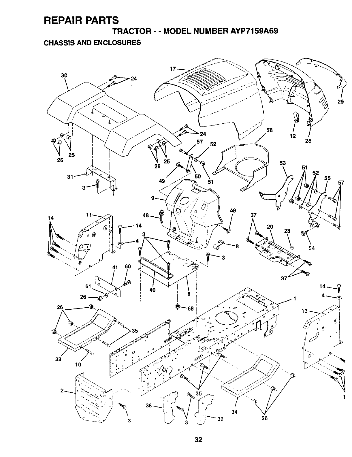
REPAIR PARTS
TRACTOR - - MODEL NUMBER AYP7159A69
CHASSIS AND ENCLOSURES
3O
26
26
29
33
10
\
3
34
26
32
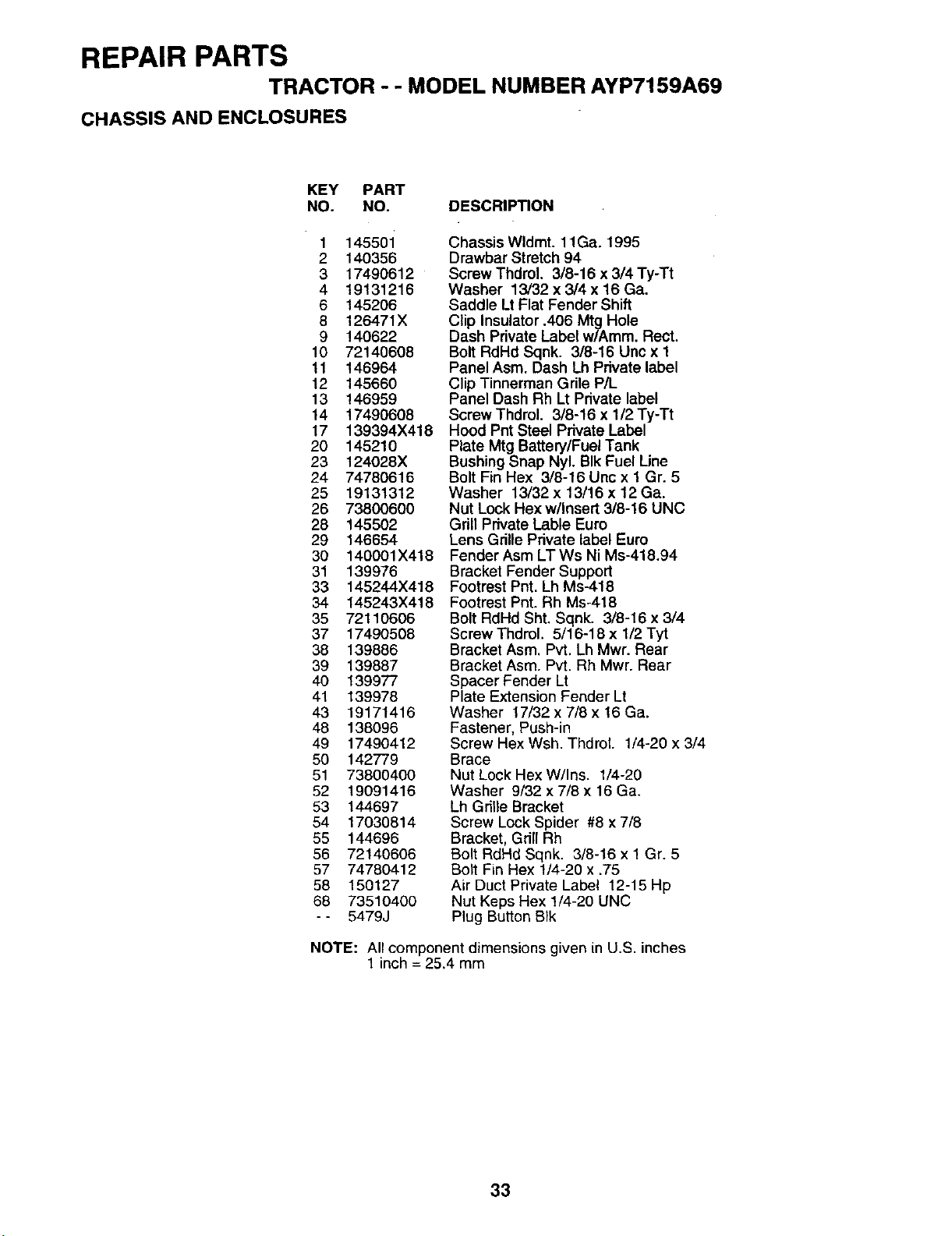
REPAIR PARTS
TRACTOR - - MODEL NUMBER AYP7159A69
CHASSIS AND ENCLOSURES
KEY PART
NO. NO. DESCRIP_ON
1 145501
2 140356
3 17490612
4 19131216
6 145206
8 126471X
9 140622
10 72140608
11 146964
12 145660
13 146959
14 17490608
17 139394X418
20 145210
23 124028X
24 74780616
25 19131312
26 73800600
28 145502
29 146654
30 140001X418
31 139976
33 145244X418
34 145243X418
35 72110606
37 17490508
38 139886
39 139887
40 139977
41 139978
43 19171416
48 138096
49 17490412
50 142779
51 73800400
52 19091416
53 144697
54 17030814
55 144696
56 72140606
57 74780412
58 150127
68 73510400
-- 5479J
Chassis Wldmt. 11Ga. 1995
Drawbar Stretch 94
Screw Thdrol. 3/8-16 x 3/4 Ty-Tt
Washer 13/32 x 3/4 x 16 Ga.
Saddle Lt Flat Fender Shift
Clip Insulator .406 Mtg Hole
Dash Private Label w/Amm. Rect.
Bolt RdHd Sqnk. 3/8-16 Unc x 1
Panel Asm. Dash Lh Private label
Clip Tinnerman Grile P/L
Panel Dash Rh Lt Private label
ScrewThdrol. 3/8-16 x l/2Ty-Tt
Hood Pnt Steel Private Label
Plate Mtg Battery/Fuel Tank
Bushing Snap Nyl. BIk Fuel Line
Bolt Fin Hex 3/8-16 Unc x 1 Gr. 5
Washer 13/32 x 13/16 x 12 Ga.
Nut Lock Hex w/Insert 3/8-16 UNC
Grill Private Lable Euro
Lens Grille Private label Euro
Fender Asm LT Ws Ni Ms-418.94
Bracket Fender Support
Footrest Pnt. Lh Ms-418
Footrest Pnt. Rh Ms-418
Bolt RdHd Sht. Sqnk. 3/8-16 x 3/4
Screw Thdml. 5/16-18 x 1/2 Tyt
Bracket Asm. Pvt. Lh Mwr. Rear
Bracket Asm. Pvt, Rh Mwr. Rear
Spacer Fender Lt
Plate Extension Fender Lt
Washer 17/32 x 7/8 x 16 Ga.
Fastener, Push-in
Screw Hex Wsh. Thdrol. 1/4-20 x 3/4
Brace
Nut Lock Hex W/Ins. 1/4-20
Washer 9/32 x 7/8 x 16 Ga.
Lh Grille Bracket
Screw Lock Spider #8 x 7/8
Bracket, Grill Rh
Bolt RdHd Sqnk. 3/8-16 x 1 Gr. 5
Bolt Fin Hex 1/4-20 x .75
Air Duct Private Label 12-15 Hp
Nut Keps Hex 1/4-20 UNC
Plug Button BIk
NOTE: All component dimensions given in U.S. inches
1 inch = 25.4 mm
33

REPAIR PARTS
TRACTOR - - MODEL NUMBER AYP7159A69
DRIVE
13
87
21
15 +I
@ 1
75
18
6
32
19
5
18
52 6
62
35
36
34
53
I
26
27
34

REPAIR PARTS
TRACTOR - - MODEL NUMBER AYP7159A69
DRIVE
KEY PART KEY PART
NO. NO. DESCRIPTION NO. NO." DESCRIPTION
1 145607 Transaxle, Dana, Model Number 47 127783
4360-97 48 123789X
2 146682 Spring, Brake Return 49 123205X
3 123666X Pulley, Transaxle 50 74760624
4 12000028 Ring, Retainer 51 73680600
5 121250X Strap, Torque 52 73800500
6 17490512 Screw, Hex, Washer, Thread 53 105710X
Rolling 5/16-18 x 3/4 55 105709X
8 141003 Rod, Shifter 56 72110610
10 76020416 Pin, Cotterl/8xl 57 130801
11 105701X Washer, Shift Plate 58 127274X
12 19151216 Washer 15/32x3/4x16Ga. 59 140312
13 74550412 Bolt 1/4-28 UNF Gr. 8 w/Patch 61 17490612
14 10040400 Washer Lock
15 74490544 Bolt, Hex Flghd 5/16-18Gr. 5 62 8883R
18 74780616 BoltFinHex3/8-16UNCx1Gr. 5 63 140186
19 73800600 Locknut3/8-16 64 71170764
21 106933X Knob 65 10040700
22 130804 Rod, Brake 66 129921
24 73350600 Nut, Hex Jam 3/8-16 70 134683
25 106888X Spring, Rod, Brake 72 19132012
26 19131316 Washer13/32 x13/16 x16 Gauge 74 109502X
27 76020412 Pin, Cotterl/8x3/4 75 121749X
28 145204 Rod, Brake, Park 76 12000001
29 124236X Cap, Plunger 77 123583X
30 130807 Bracket, Transaxle, L.H. 78 121748X
31 127275X Keeper, Belt, Transaxle, L.H. 80 131487
32 74760512 Bolt HexHd 5/16-18 UNC x 3/4 81 136933
34 149001 Shaft, Foot Pedal 82 123782X
35 120183X Bearing Nylon 83 19171216
36 19211616 Washer 21/32 x 1 x 16 Gauge 84 132183
37 1572H Pin,Roll 3/16 x 1 85 150360
38 123674X Idler, Flat 86 71208
39 74760644 Bolt, Hex 3/8-16 x 2-3/4 87 19212016
40 4470J Spacer 88 12000008
41 109070X Keeper, Belt 89 139964
42 19131312 Washer 13/32x 13/16 x 12 Gauge 90 124346X
44 105706X Bearing
45 110812X Washer, Hardened
46 12000039 Ring, Clip
Pulley, Idler
Arm, Idler
Retainer, Belt
Bolt, Hex 3/8-16 x 1-1/2
Nut, Crownlock 3/8-16
Nut, Lock Hex w/Ins 5/16-18
Link, Clutch
Spring, Return, Clutch
Bolt, RdHd Sq Neck 3/8-16 x 1.25
V-Belt, Drive
Keeper, Belt, Transaxle, R.H.
Retainer, Belt
Screw, Hex Washer Head, Thd.,
Roll. 3/8-16 x 3/4
Cover, Foot Pedal
Pulley, Engine
Bolt, Hex 7/16-20 x 4 Gr. 5
Washer, Lock Hvy Hlcl Spr 7/16
Keeper, Belt Engine LH LT
Guide Belt Mower Drive RH
Washer 13/32 x 1-1/4x 12 Ga°
Spacer, Split
Washer 25/32 x 1-1/4 x 16 Ga.
E-Ring
Key Square
Washer 25/32 x 1-5/8 x 16 Ga.
Shift Arm
Shaft, Assembly, Shifter
Spring, Torsion
Washer 17/32 x 3/4 x 16 Gauge
Rod, Tie
Nut 1/4-28
Bushing, Rod, Steering
Washer 21/32 x 1-1/4 x 16 Gauge
Ring, Klip
Console, 6 Speed
Nut, Washer Head, Self-Thread 1/4
NOTE: All component dimensions given in U.S. inches
1 inch = 25.4 mm
35
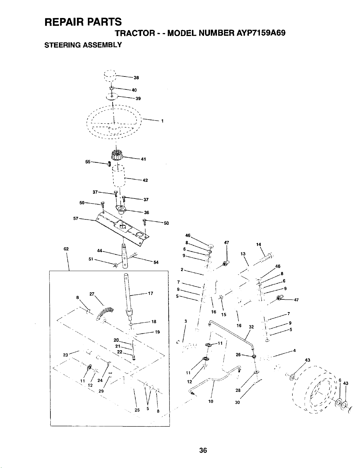
REPAIR PARTS
TRACTOR" "MODEL NUMBER AYP7159A69
STEERING ASSEMBLY
/ J
..;;::-I_-:---;:"
i • i
J
-_j.--j_\.--
62
?
14
c
\
36
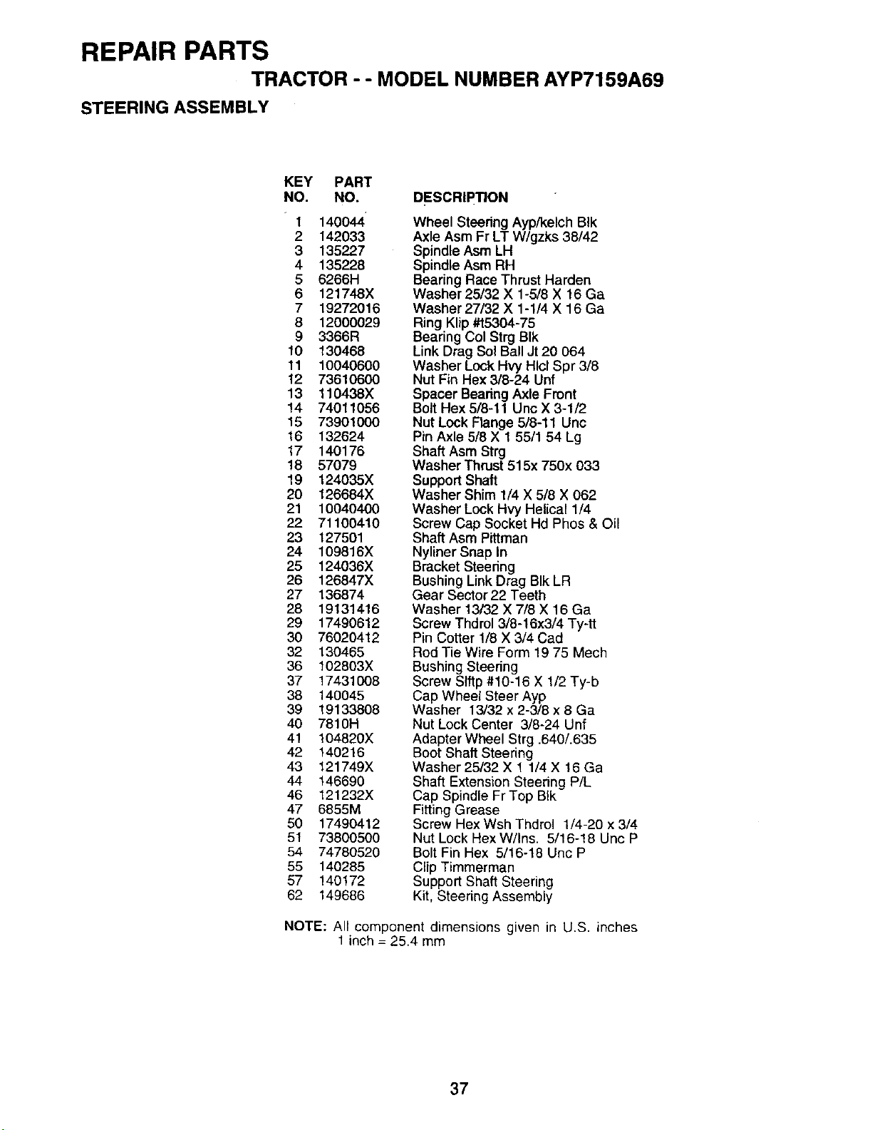
REPAIR PARTS
TRACTOR -- MODEL NUMBER AYP7159A69
STEERING ASSEMBLY
KEY PART
NO. NO.
1 140044
2 142033
3 135227
4 135228
5 6266H
6 121748X
7 19272016
8 12000029
9 3366R
10 130468
11 10040600
12 73610600
13 110438X
14 74011056
15 73901000
16 132624
17 140176
18 57079
19 124035X
20 126684X
21 10040400
22 71100410
23 127501
24 109816X
25 124036X
26 126847X
27 136874
28 19131416
29 17490612
30 76020412
32 130465
36 102803X
37 17431008
38 140045
39 19133808
40 7810H
41 104820X
42 140216
43 121749X
44 146690
46 121232X
47 6855M
50 17490412
51 73800500
54 74780520
55 140285
57 140172
62 149686
DESCRIPTION
Wheel Steering Ayp/kelch BIk
Axle Asm Fr LT W/gzks 38/42
Spindle Asm LH
Spindle Asm RH
Bearing Race Thrust Harden
Washer 25/32 X 1-5/8 X 16 Ga
Washer 27/32 X 1-1/4 X 16 Ga
Ring Klip #15304-75
Bearing Col Strg BIk
Link Drag Sol Ball Jt 20 064
Washer Lock Hvy Hlcl Spr 3/8
Nut Fin Hex 3/8-24 Unf
Spacer Bearing Axle Front
Bolt Hex 5/8-11 Unc X 3-1/2
Nut Lock Flange 5/8-11 Unc
Pin Axle 5/8 X 1 55/1 54 Lg
Shaft Asm Strg
Washer Thrust 515x 750x 033
Support Shaft
Washer Shim 1/4 X 5/8 X 062
Washer Lock Hvy Helical 1/4
Screw Cap Socket Hd Phos & Oil
Shaft Asm Pittman
Nyliner Snap In
Bracket Steedng
Bushing Link Drag BIk LR
Gear Sector 22 Teeth
Washer 13/32 X 7/8 X 16 Ga
Screw Thdrol 3/8-16x3/4 Ty-tt
Pin Cotter 1/8 X 3/4 Cad
Rod Tie Wire Form 19 75 Mech
Bushing Steering
Screw SIftp #10-16 X 1/2 Ty-b
Cap Wheel Steer Ayp
Washer 13/32 x 2-3/8 x 8 Ga
Nut Lock Center 3/8-24 Unf
Adapter Wheel Strg .640/.635
Boot Shaft Steering
Washer 25/32 X 1 1/4 X 16 Ga
Shaft Extension Steering P/L
Cap Spindle Fr Top BIk
Fitting Grease
Screw Hex Wsh Thdrol 1/4-20 x 3/4
Nut Lock Hex W/Ins. 5/16-18 Uric P
Bolt Fin Hex 5/16-t8 Uric P
Clip Timmerman
Support Shaft Steering
Kit, Steering Assembly
NOTE: All component dimensions given in U.S. inches
1 inch = 25.4 mm
37

REPAIR PARTS
TRACTOR - - MODEL NUMBER AYP7159A69
SEAT ASSEMBLY
5
23
12
KEY
NO.
1
2
3
4
5
6
7
8
9
10
12
13
PART
NO.
140116
140551
74760616
1913161O
145006
73800600
124181X
17490616
19131614
140552 •
121246X
121248X
DESCRIPTION
Seat
Bracket Pivot Seat 8 720
Bolt Fin Hex 3/8-16 Unc x 1
Washer Flat 13/32 x 1 x 10 Ga
Ctip Push In Hinged
Nut Crownlock 3/8-16 Unc
Spring Seat Cprsn 2 250 BIk Zi
Screw Thdro_ 318-16 X 1 Ty-t_
Washer 13/32 X 1 X 14 Ga
Pan Seat
Bracket Mounting Switch
Bushing Snap BIk Nyl 50 Id
KEY PART
NO. NO. DESCRIPTION
14 72050411
15 134300
16 121250X
17 123976X
21 139888
22 73800500
23 74780814
24 19171912
25 127018X
26 10040800
Bolt Rdhd Sht Nk 1/4-20xl-3/8
Spacer Split 28x 96 Yel Zinc
Spring Cprsn 1 27 BIk Pnt
Nut Lock 1/4 Lge Fig Gr 5 Zinc
Bolt Shoulder 5/16-18 Uric BIkz
Nut Lock Hex w/ins 5/16-18 Unc
Bolt Fin Hex 1/2-13 X 7/8 Gr 5
Washer 17/32 X 1-3/16 X 12 Ga
Bolt Shoulder 5/16-18 X 62
Washer Lock Hvy HIcl Spr 1/2
NOTE: All component dimensions given in U.S. inche
1 inch = 25.4 mm
38

REPAIR PARTS
TRACTOR - - MODEL NUMBER AYP7159A69
DECALS
7
2 6 3 14
10
4 6 10
13
8
16
11
15
KEY PART
NO. NO.
1 140819
2 143470
3 141579
4 141580
5 141517
6 143388
7 127520
8 133796
9 4900J
5
KEY PART
DESCRIP_ON NO. NO. DESCRIP_ON
Decal Dash Inst. Oper Eng P/L 10 141502
Decal Steering Wheel Insert 11 136832
Decal Hood RH 12 146679
Decal Hood LH 13 141583
Decal Deck Vented Wizard Plus 14 150218
Nameplate Hood Wizard Large 15 145005
Decal USA White 16 146139
Deca_ Caution Fender English - - 1383_,1
Decal Clutch/brake English -- 133671
-- 146670
Decal Chassis 16/42 6sp Wizard
Deca! V-Belt Sch
Decal Pnl Side 15.5 HP BS Vang
Decal Deck Mulching Wizard Plus
Decal Lens
Decal Bat Dan/Poi P/L Symbols
Decal Battery Dan/Poi P/L Sym Ac
Decal Handle LftHeight Adiust
Pad Footrest Ribbed
Manual Owners
WHEELS AND TIRES
2 _ 5,8
7
11
KEY PART
NO. NO.
DESCRIPTION
1
2
3
4
5
6
7
6
9
10
11
59192
65139
106222X
599O4
106732X427
278H
9040H
106108X427
122082X
7152J
104757X
Cap Valve Tire
Stem Valve
Tire F Ts 15 X 6 0 - 6 Service
Tube Front (Service Item Only)
Rim Asm 6" front White Service
Fitting Grease (Front Wheel Only)
Bearing Ftange (Front Wheel Only)
Rim Asm 8" rear White Service
Tire R Ts 20 X 10-8 C Service
Tube Rear (Service Item Only)
Cap Axle BIk 1 50 X 1 00
NOTE: All component dimensions given in U.S. inches
1 inch = 25.4 mm
39

REPAIR PARTS
TRACTOR - - MODEL NUMBER AYP7159A69
ENGINE
._ 72 62
81
13
4
4O
29
OPTIONAL EQUIPMENT
Spark Arrester
23
4O

REPAIR PARTS
TRACTOR - - MODEL NUMBER AYP7159A69
ENGINE
KEY PART
NO. NO. DESCRIPTION
1 140310
2 17720410
3
4 137352
13 272293
14 13280324
15 13200300
16 11050600
23 150554
29 137180
31 140280
32 140527
33 123487X
35 17490512
37 137040
38
40 124028X
44 17490412
46 19091416
49 17490616
62 10040500
72 71070512
78 17490620
81 128861
Control Th/ch RH BIk Pd115 10
Screw Hex Thd Cut 1/4-20x5/8 T
Engine B&S (See Breakdown)
Muffler LT B&S
Gasket Eng 1 313 Id Tin Plated
Nipple Pipe 3/8 Npt X 3"
Elbow Std 90 Degree 3/8-18 Npt
Washer Lock Ext Tooth 3/8
Shield Heat Browning Lt/Yt
Kit Spark Arrestor (Flat Scm)
Tank Fuel Front 125
Cap Asm Fuel Top Vent N/Lany
Clamp Hose BIk
Screw Thdrol. 5/16-18 x 3/4
Line Fuel 20"
Plug Oil Drain (Order From Engine
Manufacturer)
Bushing Snap Nyl BIk Fuel Line
Screw Hexwsh Thdrol 1/4-20x3/4
Washer 9/32 X 718X 16 Ga
Screw Thdrol 3/8-16 x 1 TY"I-F
Washer Lock Hvy Hlcl Spr 5116
Screw Hex Hd Cap 5/16-18 x 3/4
Screw Thdrol 3/8-16x1-1/4 TY33-
Nut Flange 1/4-20 Starter Nut
NOTE: All component dimensions given in U. S. inches
1 inch = 25.4 mm
41
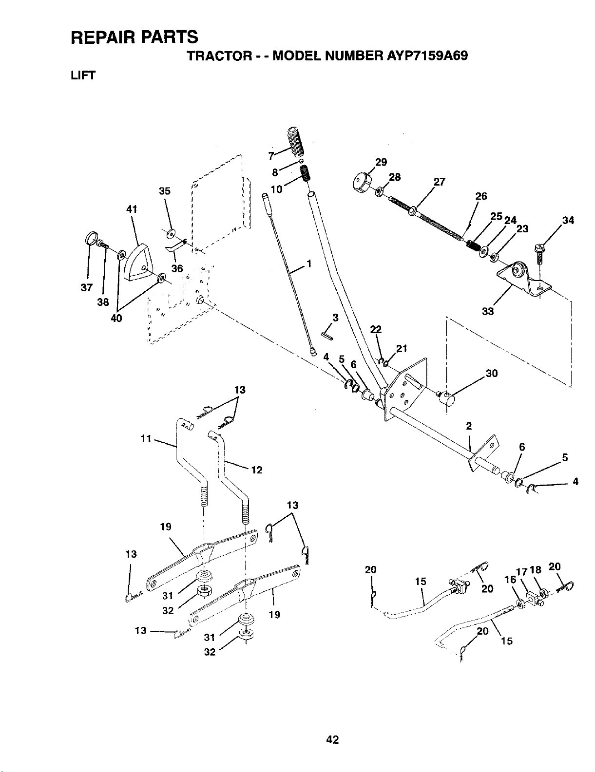
REPAIR PARTS
TRACTOR - - MODEL NUMBER AYP7159A69
LIFT
41
35
i j
29
28
27
26
34
37
13
19
3
13
22
21
33
6
5
13
13--
32
19
20 _ 1718 20
15 _\ 16\\ "_
._ y 15
42

REPAIR PARTS
TRACTOR - - MODEL NUMBER AYP7159A69
LIFT
KEY PART
NO. NO. DESCRIPTION
1 136973
2 140278
3 138284
4 12000002
5 19211621
6 120183X
7 125631X
8 122365X
10 122512X
11 139865
12 139866
13 4939M
15 127218
16 73350800
17 130171
18 73800800
19 139868
20 3146R
21 19151216
22 12000037
23 110807X
24 19131016
25 2876H
26 76020308
27 126971X
28 73350600
29 138057
30 110810X
31 140302
32 73540600
33 140168
34 17490608
35 120529X
36 123933X505
37 123935X
38 17490512
40 19112410
41 123934X
Wire Asm Inner W/Plunger
Shaft Asm Lft LH
Pin Groove
E-dng Truarc #5133-62
Washer PItd 21/32 X 1 X 21 Ga
Bearing Nylon
Grip Handle Fluted
Button Plunger Red
Spring Cprsn
Link Lift LH
Link Lift RH
Retainer Spring
Link Front
Nut Jam Hex 1/2-13 Unc
Trunnion BIk Zinc
Nut Look W/wsh 1/2-13unc
Arm Suspension Rear
Retainer Spdng
Washer 15/32 X 3/4 X 16 Ga
Ring Klip #t5304-37
Nut Special
Washer 13/32 X 5/8 X 16 Ga
Spring 2-1/8"
Pin Cotter 3/32 X 1/2
Rod Adj Lift Zinc 7.49 Wrk Lg
Nut Hex Jam 3/8-16 Uric
Knob Inf 3/8-16 Unc BIk W/sym
Trunnion Dp Stop Dbl Thds PLT
Bearing Pvt. Lift Spherical
Nut Crewnlock 3/8-24
Bracket Stop Inf. Hgt.
Screw Thdrel. 3/8-16 x 1/2 Ty, T
Washer Nylon .44 x .75 x 032
Pointer Height Indicator
Plug Hole BIk. 1.485/1.515 DIA.
Screw Thdrol 5/16-18 x 3/4
Washer 11/32 x 1-1/2 10 Ga
Scale Ind. Height BIk
NOTE: All component dimensions given in U.S. inches
1 inch = 25.4 mm
43

REPAIR PARTS
TRACTOR - - MODEL NUMBER AYP7159A69
MOWER DECK
71
43 t 52
34
.33
32
105
106
44
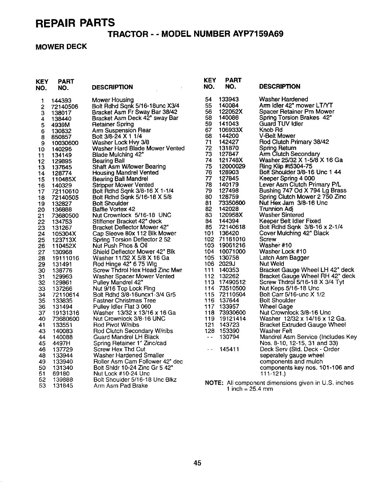
REPAIR PARTS
TRACTOR - - MODEL NUMBER AYP7159A69
MOWER DECK
KEY PART KEY PART
NO. NO. DESCRIPTION NO. NO. DESCRIPTION
1 144393
2 72140506
3 138017
4 138440
5 4939M
6 130832
8 850857
9 10030600
10 140296
11 134149
12 129895
13 137645
14 128774
15 110485X
16 140329
17 72110610
18 72140505
19 132827
20 136888
21 73680500
22 134753
23 131267
24 105304X
25 123713X
28 110452X
27 130968
28 19111016
29 131491
30 138776
31 129963
32 129861
33 137266
34 72110614
35 133835
36 131494
37 19131316
40 73680600
41 133551
43 140083
44 140088
45 4497H
46 137729
48 133944
49 133940
50 131340
51 69180
52 139888
53 131845
Mower Housing 54 133943
Bolt Rdhd Sqnk 5/16-18unc X3/4 55 140084
Bracket Asm Fr Sway Bar 38/42 56 122052X
Bracket Asm Deck 42" sway Bar 58 140086
Retainer Spring 59 141043
Arm Suspension Rear 67 106933X
Bolt 3/8-24 X 1 1/4 68 144200
Washer Lock Hvy 3/8 71 142427
Washer Hard Blade Mower Vented 72 131870
Blade Mulching 42" 73 127847
Bearing Ball 74 121748X
Shaft Asm W/lower Bearing 75 12000029
Housing Mandrel Vented 76 128903
Bearing Ball Mandrel 77 127845
Stripper Mower Vented 78 140179
Bolt Rdhd Sqnk 3/8-16 X 1-1/4 79 127498
Bolt Rdhd Sqnk 5/16-18 X 5/8 80 128759
Bolt Shoulder 81 73350600
Baffle Vortex 42 82 142028
Nut Crownlock 5/16-18 UNC 83 120958X
Stiffener Bracket 42" deck 84 144394
Bracket Deflector Mower 42" 85 72140618
Cap Sleeve 80x 112 BIk Mower 101 136420
Spdng Torsion Deflector 2 52 102 71161010
Nut Push Phos & Oil 103 19061216
Shield Deflector Mower 42" BIk 104 10071000
Washer 11/32 X 5/8 X 16 Ga 105 130758
Rod Hinge 42" 6 75 Wig 106 2029J
Screw Thdml Hex Head Zinc Mwr 111 140353
Washer Spacer Mower Vented 112 132262
Pulley Mandrel 42" 113 17490512
Nut 9/16 Top Lock Flng 114 73510500
Bolt Rdhd 3/8-16uncx1-3/4 Gr5 115 72110504
Fastner Christmas Tree 116 137644
Pulley Idler Flat 3 060 117 133957
Washer 13/32 x 13/16 x 16 Ga 118 73930600
Nut Crownlock 3/8-16 UNC 119 19121414
Rod Pivot W/nibs 121 143723
Rod Clutch Secondary W/nibs 128 153390
Guard Mandrel LH Black -- 130794
Spring Retainer 1" Zinc/cad
Screw Hex Thd Cut - - 145411
Washer Hardened Smaller
Rolter Asm Cam Follower 42" dec
Bolt Shldr 10-24 Zinc Gr 5 42"
Nut Lock #10-24 Unc
Bolt Shoulder 5/16-18 Unc Blkz
Arm Asm Pad Brake
Washer Hardened
Arm Idler 42" mower LT/Yr
Spacer Retainer Pm Mower
Spring Torsion Brakes 42"
Guard TUV Idler
Knob Rd
V-Belt Mower
Rod Clutch Primary 38/42
Spring Return
Arm Clutch Secondary
Washer 25/32 X 1-5/8 X 16 Ga
Ring Klip#t5304-75
Bolt Shoulder 3/8-16 Unc 1 44
Keeper Spdng 4 000
Lever Asm Clutch Primary P/L
Bushing 747 Od X 794 Lg Brass
Spring Clutch Mower 2 750 Zinc
Nut HexJam 3/8-16 Unc
Trunnion Adj
Washer Sintered
Keeper Belt Idler Fixed
Bolt Rdhd Sqnk 3/8-16 x 2-1/4
Cover Mulching 42" Black
Screw
Washe_"#10
Washer Lock #10
Latch Asm Bagger
Nut Weld
Bracket Gauge Wheel LH 42" deck
Bracket Gauge Wheel RH 42" deck
Screw Thdrol 5/16-18 X 3/4 Tyt
Nut Keps 5/16-18 Uric
Bolt Carr 5/16-unc X 1/2
Bolt Shoulder
Wheel Gage
Nut Crownlock 3/8-16 Unc
Washer 12/32 x 14/16 x 12 Ga.
Bracket Extruded Gauge Wheel
Washer Felt
Mandrel Asm Service (Includes Key
Nos. 8-10, 12-15, 31 and 33)
Deck Serv (Std. Deck - Order
seperately gauge wheel
components and mulch
components key nos. 101-106 and
111-121.)
NOTE: All component dimensions given in U.S. inches
1 inch = 25.4 mm
45

REPAIR PARTS
TRACTOR - - MODEL NUMBER AYP7159A69
DANA TRANSAXLE - MODEL NUMBER 4360-97
9
26
27
37
52
20
21
22
55
36
54
24
25
/
32
33
34
35
19
40
41
55
_6
57
6
42
44
46
12
47
48
59 49
56 50
55
51
19
6O
8
62
63
66
59
64
65
7O
68
69
67
43*52
46

REPAIR PARTS
TRACTOR - - MODEL NUMBER AYP7159A69
DANA TRANSAXLE - MODEL NUMBER 4360-97
KEY PART KEY PART
NO. NO. DESCRIPTION NO. NO. DESCRIPTION
1 132671
2 2274J
3 134400
4 105904X
5 105905X
6 134788
7 134399
8 120951X
9 148266
10 2225J
11 134793
12 143679
13 120415X
14 142674
15 106846X
16 106095X
17 105909X
18 105910X
19 105911X
20 142675
21 138246
22 138238
23 148268
24 143673
25 2244J
26 105916X
27 120470X
28 110070X
29 142677
30 142681
31 124644X
32 108980X
33 120406X
34 134796
35 105925X
36 2232J
37 108978X
38 110079X
Housing, Upper 39 124639X
Screw, Tapping, Large 40 120472X
1/4-20 x .734 41 105928X
Ball, Detent 42 106605X
Spring, Detent 43 134394
Screw, Set 44 120473X
Kit, Shifter Assembly 45 106596X
Boot, Shifter
Puck, Friction 46 142678
Bearing, Flange 47 120407X
Ring, Retaining 48 106589X
Assembly, Kit, Shim, .625 Shaft 49 120408X
Gear, Spur, 15 Teeth (2-) 50 105937X
Washer, Plain .632 x 1.38 x .046 51 2226J
Key, Woodruff, #9 52 134401
Assembly, Kit, Input Shaft 53 2264J
Pinion, Bevel, 14 Teeth 54 120474X
Ring, Retaining 55 110081X
Chain, 24 Pitches 56 105941X
Bearing, Flange 57 110071X
Gear, Spur, 14 Teeth 58 120952X
Collar, Clutch 59 106592X
Assembly, Kit, Clutch Keys 60 120475X
Beadng, Flange 61 142680
Shaft, Intermediate 62 120961X
Key, Woodruff, #61 63 7294J
Ring, Retaining 64 108989X
Sprocket, 18 Teeth (Reverse) 65 120953X
Spacer 66 120954X
Gear, Spur, 37 Teeth (1-) 67 134799
Gear, Spur, 35 Teeth (2-,) 68 138244
Gear, Spur, 30 Teeth (3") 69 108996X
Gear, Spur, 25 Teeth (4-) 70 120956X
Gear, Spur, 22 Teeth (5-) 71 73810500
Gear, Spur, 19 Teeth (6_) 72 148269
Washer, Plain .640 x 1.37 x .061 73 120416X
Washer, Plain .632 x 1.00 x .026
Spacer .630 x 1.00 x .169
Assembly, Gear, Combination,
12 Teeth and 35 Teeth
Shaft, Idler
Spacer .633 x .87 x .755
Sprocket, 9 Teeth (Reverse)
Gear, Bevel, 42 Teeth
Assembly, Kit, Shim, .750 Shaft
Shaft, Drive
Screw, Tapping, Large
5/16-18 x 1.44
Gear, Spur, 12 Teeth (1-)
Gear, Spur, 20 Teeth (3-)
Gear, Spur, 25 Teeth (4,)
Gear, Spur, 28 Teeth (5_)
Gear, Spur, 31 Teeth (6)
Washer, Plain .632 x 1.00 x .060
Washer, Neoprene
Washer, Plain .758 x 1.25 x .031
Axle, L.H.
Gear, Miter, 15 Teeth
Ring, Retaining
Gear, Spur, 32 Teeth
Shaft, Cross
Gear, Miter, 15 Teeth
Axle, R.H.
Housing, Lower
Puck, Friction
Disc, Brake
Spacer
Jaw, Brake
Pin, Dowel
Screw, Tapping 5/16-18 x 2.25
Lever, Actuating
Washer, Plain .321 x 1.00 x .055
Bracket, Anti-Rotation
Locknut 5/16-24
Seal, Oil
Grease
NOTE: All component dimensions given in U.S. inches
1 inch = 25.4 mm
47
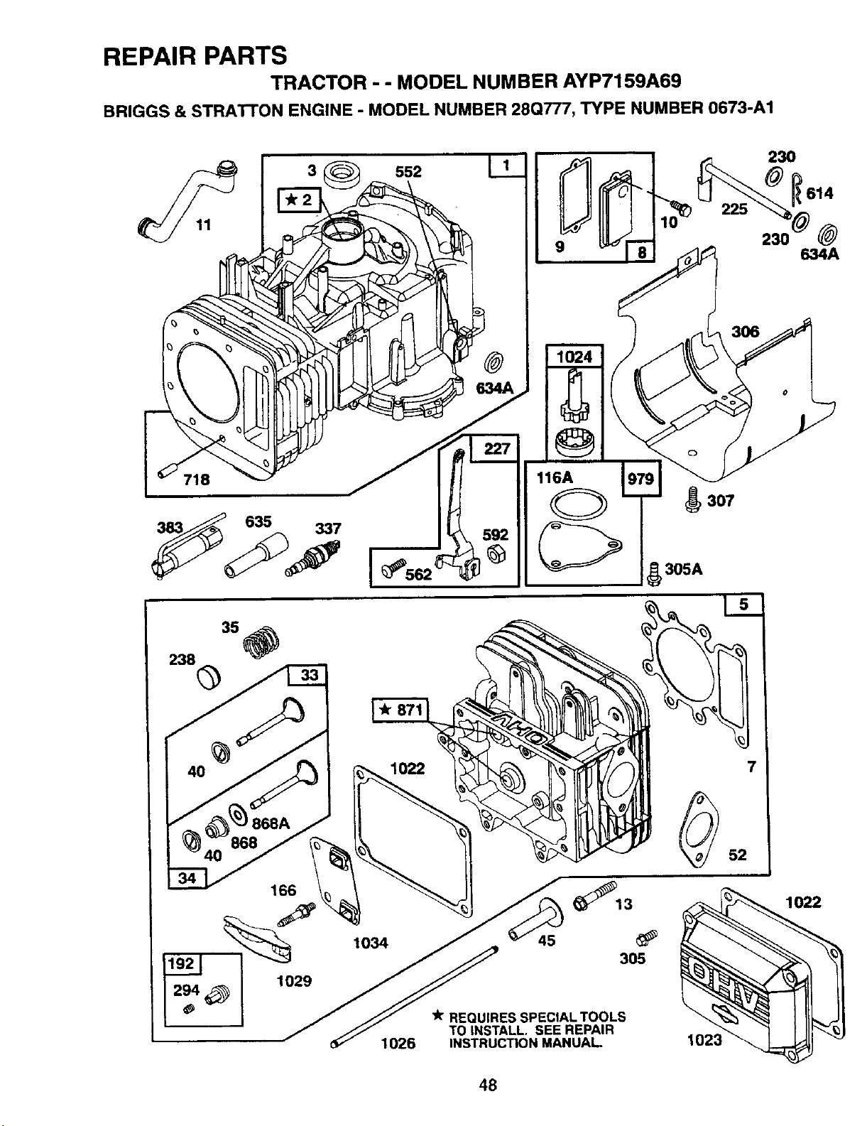
REPAIR PARTS
TRACTOR - - MODEL NUMBER AYP7159A69
BRIGGS & STRATFON ENGINE - MODEL NUMBER 28Q777, TYPE NUMBER 0673-A1
238 35
@
23O
634A
116A
_ 307
5_ 305A
_13
lo34 45
3O5
1026
REQUIRES SPECIAL TOOLS
TO INSTALL. SEE REPAIR
INSTRUCTION MANUAL
7
52
1023
1022
48
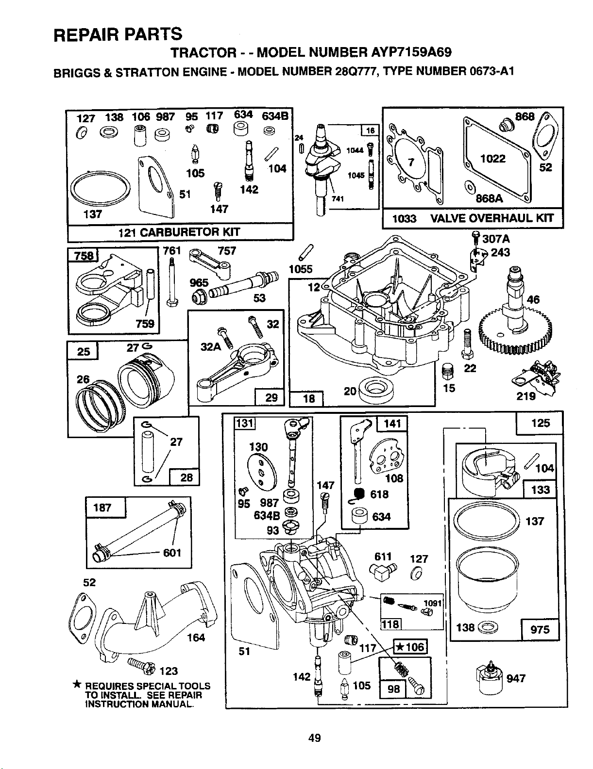
REPAIR PARTS
TRACTOR - - MODEL NUMBER AYP7159A69
BRIGGS & STRATTON ENGINE - MODEL NUMBER 28Q777, TYPE NUMBER 0673-A1
127 138 106 987 95 117 634 634B
¢
2
51 142
137 7
121 CARBURETOR KIT
1022
1033 VALVE OVERHAUL KIT
137
947
49

REPAIR PARTS
TRACTOR - - MODEL NUMBER AYP7159A69
BRIGGS & STRATTON ENGINE - MODEL NUMBER 28Q777, TYPE NUMBER 0673-A1
523
284A
304A
1000
_P
305A
2_634A 842 524 868 868A
358 GASKET SET
I O 138
@
137
977 CARBURETOR GASKET SET
1000A
305A
188A
1005
_ 1044
G 75
467
171 _ 535
_224
334
445
53'
646_ _)28_
50

REPAIR PARTS
TRACTOR - - MODEL NUMBER AYP7159A69
BRIGGS & STRA'I'rON ENGINE - MODEL NUMBER 28Q777, TYPE NUMBER 0673-A1
216
232
305B '
305A
265
ii Jl.i
1027
305A
1019 LABEL KIT I
3O4
482
1058 OWNER'S MANUAL I
877
801
728
615
544
311
1090
I
I
51

HOW AND WHERE TO ORDER PARTS
You can identify your product correctly by looking at itsmodel number label which is located under the seat.
1. A. Name the product that needs a part, for example: tractor.
B. State the product's model number and factory number. These numbers appear on a label on the product.
2. List the description and part numberofthe part you want. This manual shows drawings, descriptions, and part
numbers.
3. You may order from a participating Western Auto store. If you cannot do that, please order direct from:
Telephone: 1-800-633-8434
Western Auto National Parts Center
2107 Grand Avenue
Kansas City, MO64108
150231 REV. 2 08.27.96 RH
PRINTED IN U.S.A.