

917.259930
Western Auto.
Operation and Service Instructions
Wizard Lawn Tractor
Stock Number
93-9159-0
Model Number
AYP9159B69
Factory Number
AYP9159B69
This product has a low emission engine which operates differ-
ently from previously built engines. Before you start the'engine,
read end understand this Owner's Manual.
Thank you for purchasing an American-built product.
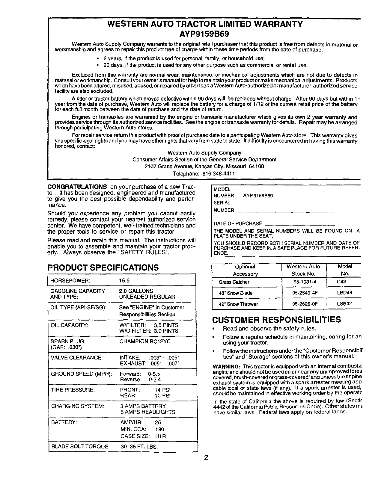
WESTERN AUTO TRACTOR LIMITED WARRANTY
AYP9159B69
Western Auto Supply Company warrantsto the original retail purchaser that this product is free from defects in material or
workmanship and agrees to repair this product free of charge within these time periods from the date of purchase:
• 2 years, if the product is used for personal, family, or household use;
90 days, if the product is used for any other purpose such as commercial or rental use.
Excluded from this warranty are normal wear, maintenance, or mechanical adjustments which are not due to defects in
materialorworkmanship. C_nsu_ty_ur_wner_smanua_f_rhe__t_m_intainy_urproduct_rmakemechanica_adjustments_ Products
which have been altered, misused, abused, or rePaired by other than a Western Auto-authorized or manufactu rer-authorized service
facility are also excluded.
A nder or tractor battery which proves defective within 90 days will be replaced without charge. After 90 days but within 1_
year from the date of purchase, Western Auto will replace the battery for acharge of 1/12 of the current retail price of the battery
for each full month between the date of purchase and the date of return.
Engines or transaxles are warranted by the engine or transexle manufacturer which gives its own 2 year warranty and
providesservicethroughitsauthorizedservicefacilitles. Seetheengineortransaxlewarrantyfordetails. Repalrmaybearranged
through participating Western Auto stores.
For repair service return this product with proof of purchase date to a participating Western Auto store. This warranty gives
Sou specificlegal rights and you may have other rights that vary from state to state. Ifdifficulty is encountered in having this warranty
onored, contact:
Westem Auto Supply Company
Consumer Affairs Section of the General Service Department
2107 Grand Avenue, Kansas City, Missouri 64108
Telephone: 816 346-4411
CONGRATULATIONS on your purchase of a new Trac-
tor. It has been designed, engineered and manufactured
to give you the best possible dependability and perfor-
mance.
Should you experience any problem you cannot easily
remedy, please contact your nearest authorized service
center. We have competent, well-trained technicians and
the proper tools to service or repair this tractor.
Please read and retain this manual The instructions will
enable you to assemble and maintain your tr.actor prop-
erly. Always observe the SAFETY RULES.
MODEL
NUMBER AYP9159B6g
SERIAL
NUMBER
DATE OF PURCHASE
THE MODEL AND SERIAL NUMBERS WILL BE FOUND ON A
PLATE UNDER THE SEAT.
YOU SHOULD RECORD BOTH SERIAL NUMBER AND DATE OF
PURCHASE AND KEEP IN A SAFE pLACE FOR FUTURE REFER-
ENCE,
PRODUCT SPECIFICATIONS
HORSEPOWER: 15.5
GASOLINE CAPACITY 2,0 GALLONS
AND TYPE: UNLEADED REGULAR
OIL TYPE (API-SF/SG): See "ENGINE" in Customer
Responsibilities Section
OIL CAPACITY: W/FILTER: 3,5 PINTS
W/O FILTER: 3.0 PINTS
SPARK PLUG: CHAMPION RC12YC
(GAP: .030")
VALVE CLEARANCE: INTAKE: .003" - .005"
EXHAUST: .005" - .007"
GROUND SPEED (MPH): Forward: 0-5.5
Reverse 0-2.4
TIRE PRESSURE: FRONT: 14 PSi
REAR: 10 PSI
CHARGING SYSTEM: 3 AMPS BATTERY
5 AMPS HEADLIGHTS
BATTERY: AMP/HR: 25
MIN CCA: 190
CASE SIZE: U1R
BLADE BOLT TORQUE: 30-35 FT. LBS.
Optional Western Auto Model
Accessory Stock No. No.
Grass Catcher 95-1031-4 C42
48" Snow Blade 95-2549-4F LBD4S
42" Snow Thrower 95-2626-0F LSB42
CUSTOMER RESPONSIBILITIES
• Read and observe the safety rules.
Follow a regular schedule in maintaining, caring for an
using your tractor.
Follow the instructions under the "Customer Responsibtt
ties" and "Storage" sections of this owner's manual.
WARNING: This tractor is equipped with an internal combust_c
engine and should notbe used onor near any unimproved fores
covered,brush-covered orgrass-covered land unless the engine
exhaust system is equipped with a spark arrester meeting app!
cable local or state laws (if any). If a spark arrester is used,
should be maintained in effective working order by the operatc
In the state of California the above is required by law (Sectic
4442 ofthe California Public Resources Code). Other states m_
have similar laws. Federal laws apply on federal lands.
2
i lb SAFETY RULES
Safe Operation Practices for Ride-On Mowers A
IMPORTANT: THIS CUTTING MACHINE IS CAPABLE OF AMPUTATING HANDS AND FEET AND THROWING OBJECTS.
FAILURE TO OBSERVE THE FOLLOWING SAFETY INSTRUCTIONS COULD RESULT IN SERIOUS INJURY OR DEATH.
I. GENERAL OPERATION
• Read, understand, and follow all instructions in the manual
and on the machine before starting.
• Only allow responsible adults, who are familiar with the
instructions, to operate the machine.
Clear the area of objects such as rocks, toys, wire, etc.,
which could be picked up and thrown by the blade.
Be surethe area isclearof otherpeople before mowing. Stop
machine if anyone enters the area.
Never carry passengers.
Do not mow inreverse unless absolutely necessary. Always
lookdown and behind before and while backing.
Be aware of the mower discharge direction and do not point
it at anyone. Do not operate the mower without either the
entire grass catcher or the guard in place.
• Slow down before turning.
Never leave a runningmachine unattended. Always tum off
blades, set parking brake, stop engine, and remove keys
before dismounting.
Turn off blades when not mowing.
• Stop engine before removing grass catcher or unclogging
chute.
Mow only in daylightor good artificial light.
Do not operate the machine while under the influence of
alcohol or drugS.
Watch for traffic when operating near orcrossing roadways.
Use extra care when loading or unloading the machine into
a trailer or truck.
IL SLOPE OPERATION
Slopes are a major factor related to loss-of-control and
tipover accidents, which can result in severe injury or
death. All slopes requireextre caution. If you cannot back
up the slope or if you feel uneasy on it, do not mow it.
DO:
• Mow up and down slopes, not across.
Remove obstacles such as rocks, tree limbs, etc.
Watch for holes, ruts, or bumps. Uneven terrain could
overturn the machine. Tafl grass can hide obstacles.
Use slowspeed. Choose a low gear so that you willnot have
to stop or shift while on the slope.
Follow the manufacturer's recommendations for wheel
weights or counterweights to improve stability.
Use extra care with grass catchers or other attachments.
These can change the stability of the machine.
Keep all movement on the slopes slowand gradual. Do not
make sudden changes in speed or direction.
Avoid starting or stopping on a slope. If tires lose traction,
disengage the blades and proceed slowly straight down the
slope.
DO NOT:
• Donottumonslopesunlessnecessary, andthen, tumslowly
and gradually downhill, if possible.
Do not mow near drop-offs, ditches, or embankments. The
mower could suddenly tum over if a wheel is over the edge
of a cliff or ditch, or if an edge caves in.
Do not mow on wet grass. Reduced traction could cause
sliding.
Do not try to stabilize the machine by putting your foot on the
ground.
Do not use grass catcher on steep slopes.
III. CHILDREN
Tragic accidents can occur if the operator is not alert to the
presence of children. Children are often attracted to the
machine and the mowing activity. Never assume that
children will remain where you last saw them.
" • Keep children outof the mowingarea and under the watchful
care of another responsible adult.
Be alert and turn machine off if children enter the area.
Before and when backing, look behind and down for small
children.
Never carry children. They may fall off and be seriously
injured or interfere with safe machine operation.
Never allow children to operate the machine.
Use extra care when approaching blind corners, shrubs,
trees, or other objects that may obscure vision.
IV. SERVICE
Use extracare inhandling gasoline and other fuels. They are
flammable and vapors are explosive,
Use only an approved container.
Never remove gas cap or add fuel with the engine
running. Allow engine to cool before refueling. Do not
smoke.
Never refuel the machine indoors.
Never store the machine or fuel container inside where
there is an open flame, such as a water heater.
Never run a machine inside a closed area.
Keep nuts and botts, especially blade attachment bolts, tight
and keep equipment in good condition.
Never tamper with safety devices. Check their proper
operation regularly.
Keep machine tree of grass, leaves, or other debris build-up.
Clean oil or fuel spillage. Allow machine to cool before
stodng.
Stop and inspect the equipment if you strike an object.
Repair, if necessary, before restarting.
Never make adjustments or repairs with the engine running.
Grass catcher components are subject to wear, damage, and
deterioration, which could expose moving parts or allow
objects to be thrown. Frequently check components and
replace with manufecturer's recommended parts, when nec-
essary.
Mower blades are sharp and can cut. Wrap the blade(s) or
wear gloves, and use extra caution when servicing them.
Check brake operation frequently. Adjust and service as
required.
Look for this symbol to point out important
safety precautions, tt means
CAUTION!!! BECOME ALERT!!! YOUR
SAFETY IS INVOLVED.
CAUTION: Always disconnect spark plug
wire and place wire where it cannot contact
spark plug in order to prevent accidental
starting when setting up, transporting,
adjusting or making repairs.
/Ik WARNING
The engine exhaust from this product contains
chemicals known to the State of California to
cause cancer, birth defects, or other reproduc-
tive harm.
3
TABLE OF CONTENTS
SAFETY RULES ......................... ;.................................. 3
PRODUCT SPECIFICATIONS ...................................... 2
CUSTOMER RESPONSIBILITIES ..................... 2, 15-19
WARRANTY .................................................................. 2
ASSEMBLY ............................................................... 6-8
OPERATION ............................................................ 9-14
MAINTENANCE SCHEDULE ..................................... 15
SERVICE AND ADJUSTMENTS ........................... 20-;
STORAGE ................................................................... ;
TROUBLESHOOTING ........................................... 27-:
REPAIR PARTS - TRACTOR ................................ 30
REPAIR PARTS - ENGINE .................................... 48-._
PARTS ORDERING/SERVICE ............... BACK COVE
INDEX
A
Adjustments:
Brake ............................................ 22
Carburetor .................................... 25
Mower
Front-To-Back ......................... 21
Side-To-Side ........................... 20
"r_..'otlle Control Cable .................. 25
Air Filter, Engine .................................. 18
Air Screen, Engine .............................. 18
Assembly ............................................ 6-8
B
Battery:
Charging ........................................ 7
Cleaning ....................................... 16
Starting with Weak Battery ........... 23
Storage ........................................ 26
Terminals ..................................... 16
Belt:
Motion Ddve
Removal/Replacement ............ 22
Mower Belt(s)
Removal/Replacement ............ 21
Blade:
Sharpening ................................... 16
Replacement ................................ 16
Brake Adjustment ................................ 22
C
Carburetor Adjustment ........................ 25
Controls, Tractor ................................. 10
Customer Responsibilities .............. 15-19
Engine:
Air Filter .................................... 18
Air Screen ................................ 18
Cooling Fins ............................. 18
Engine Oil ........................... 12,17
Fuel Filter ................................. 19
Spark Plug(s) ........................... 19
Tractor:
Battery ...................................... 16
Blade ........................................ t 6
Lubrication Chart ...................... 15
Maintenance Schedule ............ 15
Tire Care .......................... 8,16,23
Transaxle ................................. 17
Cutting Height, Mower ......................... 11
E
Electrical:
Interlocks and Relays ................... 24
Schematic .................................... 29
Wiring Diagram ............................ 30
Engine:
Air Filter ........................................ 18
Air Screen .................................... 18
Cooling Fins ................................. 18
Oil Change ................................... 17
Oil Level ....................................... 12
Oil Type ................................... 12,17
Preparation .................................. 12
Repair Parts ............................ 48-53
Starting ......................................... 13
Storage ........................................ 26
F
Filter:
Air Filter ........................................ 18
Fuel .............................................. 19
Fuel:
Type ............................................. 12
Storage ........................................ 26
Fuse .................................................... 24
H
Hood Removal/Installation .................. 24
L
Leveling Mower Deck .......................... 21
Lubrication:
Chart ............................................ 15
Engine .......................................... 17
M
Maintenance Schedule ....................... 15
Mower:
Adjustment, Front-to-Back ........... 21
Adjustment, Side-to-Side ............. 20
Blade Replacement ...................... 16
Blade Sharpening ........................ 16
Cutting Height .............................. 11
Installation.................................... 20
Operation ..................................... 12
Removal ....................................... 20
Mowing Tips ........................................ 14
Muffler ................................................. 19
Spark Arrester ........................... 2,40
O
Oil:
Cold Weather Conditions ........ 12,17
Engine .......................................... 17
Storage ........................................ 26
Operation ......................................... 9-14
Operating Mower ................................. 12
Options:
Accessories ....................................
Spark Arrester ........................... 2,,
P
Parking Brake ................................. 10-'
Parts Bag ..............................................
Parts, Replacement/Repair ............ 30-,
Product Specifications ...........................
R
Repair Parts ................................... 30-,
S
Safety Rules ..........................................
Seat .......................................................
Service and Adjustments ............... 20<
Carburetor .................................... ;
Fuse ............................................. ;
Hood Removal/Installation ........... ;
Motion Drive Belt
Removal/Replacement ............ :
Mower Belt(s)
Removal/Replacement ............ :
Mower Adjustment
Front-to-Back ...........................
Side-to-Side ............................
Mower Removal/Installation .........
Tire Care .............................. 8,16,
Slope Guide Sheet ..............................
Spark Plug(s) ......................................
Specifications .......................................
Starting the Engine ........................ 12-
Steering Wheel ................................. 6,
Stopping the Tractor ............................
Storage ................................................
T
Throttle Control Cable Adjustment ......
Tires ............................................ 8,16
Troubleshooting Chart .................... 27-
Transaxle ....................................... 46.
W
Warranty ..............................................
Wiring Diagram ...................................
Wiring Schematic ................................
4
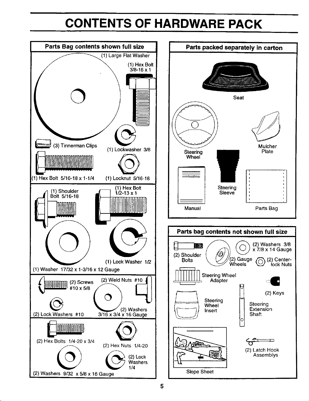
CONTENTS OF HARDWARE PACK
Parts Bag contents shown full size
(1) Large Flat Washer
©
_(3) Tinnerman Clips
{1) Hex Bolt 5/16-18 x 1-1/4
(1) Hex Bolt
3/8-16 x
(1) Lockwasher 3/8
@
(1) Locknut 5/16-18
(1) Shoulder
Bolt 5/16-18
©
(1) Hex Bolt
1/2-13 x 1
(1) Lock Washer 1/2
(1) Washer 17/32 x 1-3/16 x 12 Gauge
@21 Washers
(2) Lock Washers #10 3/16 x 3/4 x 16 Gauge
(2) Hex Bolts 1/4-20 x 3/4
(2) Hex Nuts 1/4-20
(2) Lock
Washers
1/4
(2) Washers 9/32 x 5/8 x 16 Gauge
Parts packed separately in carton
Seat
Steering
Wheel
L
S_ee?e_i
Mulcher
Plate
Manual Pads Bag
Parts bag contents not shown full size
_ _ (2)Washers 3/8
(2) Shoulder (/_) _._.J x 7/8x 14 Gauge
Bolts \ t,...///(2) Gauge ,_ (2) Center-
Wheels "_J lock Nuts
_L_ Steering Wheel
, , Adapter
Steering
Wheel
Inse_
=_X€
t (2) Keys
Steering
Extension
Shaft
(2) Latch Hook
Assemblys
Slope Sheet
ASSEMBLY
Your new tractor has been assembled at the factory with exception of those parts left unassembled for shipping purposes
To ensure safe and proper operation of your tractor all parts and hardware you assemble must be tightened securely• Us(
the correct tools as necessary to insure proper tightness•
TOOLS REQUIRED FOR ASSEMBLY
A socket wrench set will make assembly easier. Standard
wrench sizes are listed.
(1) 3/4" Socket w/drive rachet Utility knife
(2) 7/16" wrenches Tire pressure gauge
(2) 1/2" wrenches
(1) 9/16" wrench
When fight or left hand is mentioned in this manual, it
means when you are in the operating position (seated
behind the steering wheel).
TO REMOVE TRACTOR FROM CARTON
UNPACK CARTON
Remove all accessible loose parts and parts cartons
from carton (See page 5).
Cut, from top to bottom, along lines on all four comers
of carton, and lay panels flat,
Check for any additional loose parts or cartons and
remove.
BEFORE ROLUNG TRACTOR OFF SKID
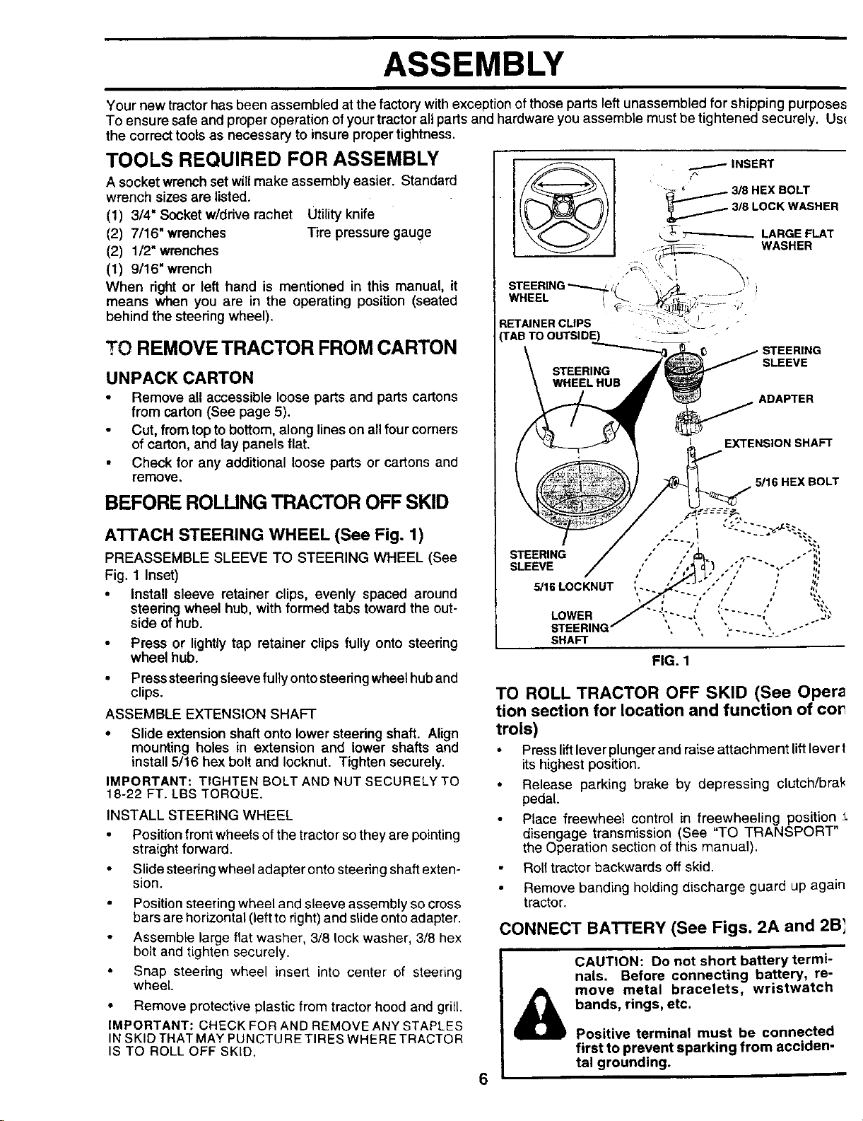
ATTACH STEERING WHEEL (See Fig. 1)
PREASSEMBLE SLEEVE TO STEERING WHEEL (See
Fig. 1 Inset)
• Install sleeve retainer clips, evenly spaced around
steering wheel hub, with formed tabs toward the out-
side of hub.
Press or lightly tap retainer clips fully onto steering
wheel hub.
Press steering sleeve fully onto steering wheel hub and
clips.
ASSEMBLE EXTENSION SHAFT
• Slide extension shaft onto lower steering shaft. Align
mounting holes in extension and lower shafts and
install 5/16 hex bolt and Iocknut. Tighten securely.
IMPORTANT: TIGHTEN BOLT AND NUT SECURELY TO
18-22 FT. LBS TORQUE•
INSTALL STEERING WHEEL
Position front wheels of the tractor so they are pointing
straight forward.
Slide steering wheel adapter onto stee ring shaft exten-
sion.
Position steering wheel and sleeve assembly so cross
bars are horizontal (left to rig ht)and slide onto adapte r.
Assemble large flat washer, 3/8 lock washer, 3/8 hex
bolt and tighten securely.
Snap steering wheel insert into center of steering
wheel
• Remove protective plastic from tractor hood and grill.
IMPORTANT: CHECK FOR AND REMOVE ANY STAPLES
IN SKID THAT MAY PUNCTU RE TIRES WHERE TRACTOR
IS TO ROLL OFF SKID,
INSERT
• _ " 3/8HEXBOLT
_3/8 LOCKWASHER
k_T_--------.-_ LARGEPLAT
WASHER
STEERING _," _",1/_ J '
WHEEL i _ _<'_-'_i" "- '
RETAINER CUPS _T:_:"_.L - .
rAB TO OUTSIDE) - . _'
\ STEER,NG# SLEEVE
WHEELHUB _r _i_
\ J ,_ ___ ADAPTER
I _l _" 1 1 EXTENSION SHAFT
_ 5/16 HEX BOLT
STEERING / ,'" /'_/,_, .,-. ." ." "'4',
SLEEVE
5/lSLOCKNUT ,.. _. :"," ," , ,,
STEERING / , \, ";..... ",,.o.--'"
SHAFT
FIG. 1
TO ROLL TRACTOR OFF SKID (See Opera
tion section for location and function of cot
trois)
Press liftlever plunger and raise attachment lift lever I
its highest position.
Release parking brake by depressing clutch/bral<
pedal.
Place freewheel control in freewheeling position
disengage transmission (See "TO TRANSPORT"
the Operation section of this manual).
Roll tractor backwards off skid.
Remove banding holding discharge guard up again
tractor.
CONNECT BAI-rERY (See Figs. 2A and 2B_
6
&
CAUTION: Do not short battery termi-
nals. Before connecting battery, re-
move metal bracelets, wristwatch
bands, rings, etc.
Positive terminal must be connected
first to prevent sparking from acciden-
tal grounding.
ASSEMBLY
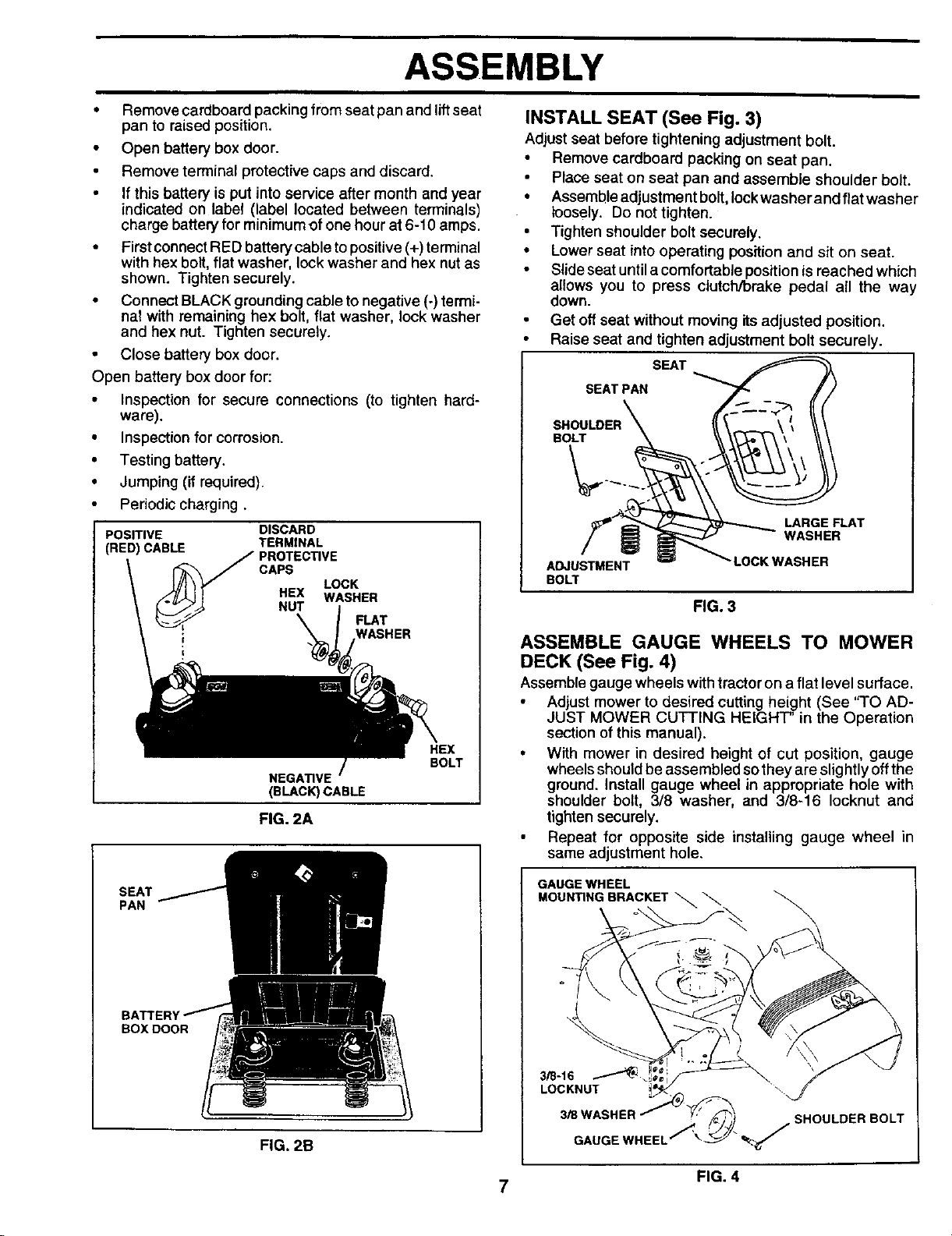
• Remove cardboard packing from seat pan and lift seat
pan to raised position.
• Open battery box door.
• Remove terminal protective caps and discard.
• If this battery is put into service after month and year
indicated on label (label located between terminals)
charge battery for minimum of one hour at 6-10 amps.
• First cennect RED battery cable to positive (+) terminal
with hex bolt, flat washer, lock washer and hex nut as
shown. Tighten securely.
• Connect BLACK grounding cable to negative (-) termi-
nal with remaining hex bolt, flat washer, lock washer
and hex nut. Tighten securely.
• Close battery box door.
Open battery box door for:
• Inspection for secure connections (to tighten hard-
ware).
• Inspection for corrosion.
• Testing battery.
• Jumping (if required).
Periodic charging.
POSITIVE DISCARD
(RED) CABLE TERMINAL
CAPS
LOCK
HEX WASHER
FLAT
WASHER
NEGATIVE
(BLACK) CABLE
FIG. 2A
HEX
BOLT
SEAT
PAN
BOX DOOR
FIG. 2B
INSTALL SEAT (See Fig. 3)
Adjust seat before tightening adjustment bolt.
• Remove cardboard packing on seat pan.
Place seat on seat pan and assemble shoulder bolt.
• Assembleadjustment bolt, lock washer and flat washer
loosely, Do not tighten.
• Tighten shoulder boltsecurely.
• Lower seat into operating position and sit on seat.
• Slideseat untila comfortable positionisreached which
allows you to press clutch/brake pedal all the way
down.
Get oftseat without moving itsadjusted position.
Raise seat and tighten adjustment bolt securely.
SEAT
SEAT PAN
BOLT
ADJUSTMENT
BOLT
LARGE FLAT
WASHER
LOCK WASHER
FIG. 3
ASSEMBLE GAUGE WHEELS TO MOWER
DECK (See Fig. 4)
Assemble gauge wheels with tractoron a flat level surface,
Adjust mower to desired cutting height (See "TO AD-
JUST MOWER CUTTING HEIGHT" in the Operation
sectionof this manual).
• With mower in desired height of cut position, gauge
wheels should beassembled sothey are slightlyoff the
ground. Install gauge wheel in appropriate hole with
shoulder bolt, 3/8 washer, and 3/8-16 Iocknut and
tighten securely.
Repeat for opposite side installing gauge wheel in
same adjustment hole.
GAUGE WHEEL
MOUN_NG BRACKET_
;HOULDER BOLT
FIG. 4
7
ASSEMBLY
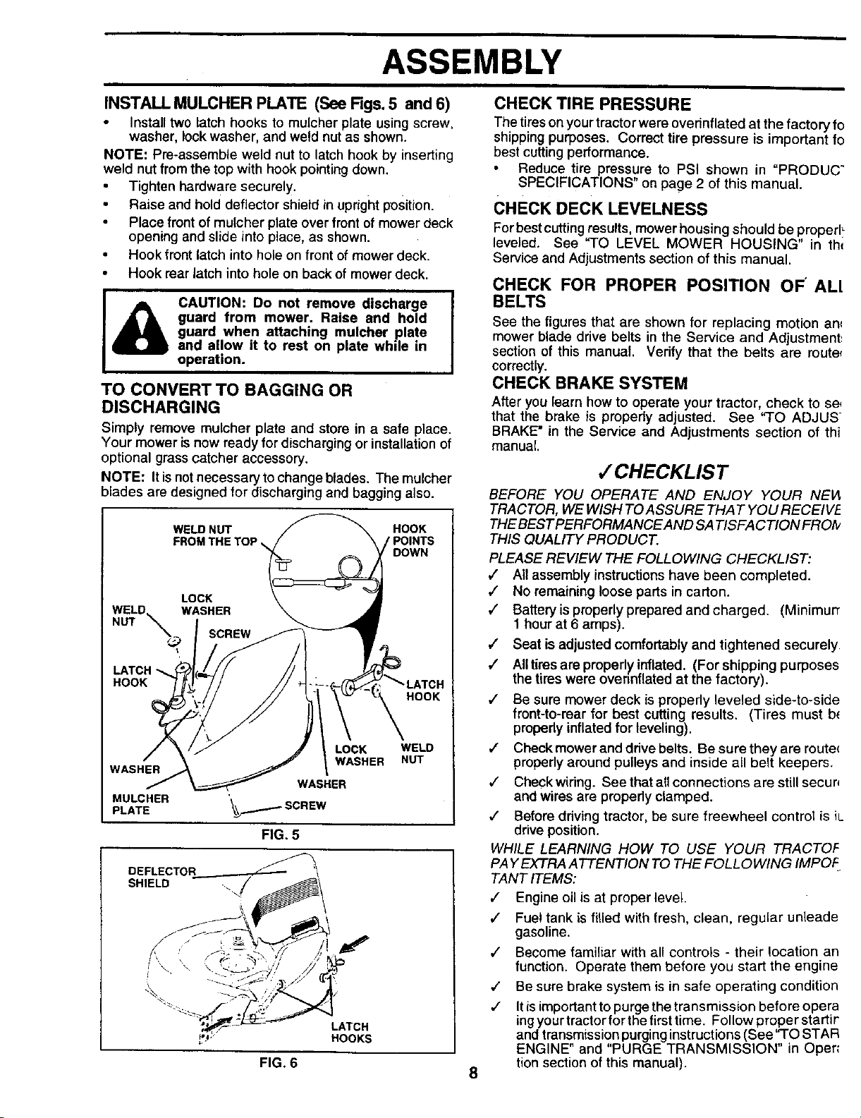
INSTALL MULCHER PLATE (See Figs. 5 and 6)
• Install two latch hooks to mulcher plate using screw,
washer, lockwasher, and weld nut as shown.
NOTE: Pre-assembte weld nut to latch hook by inserting
weld nut from the top with hook pointingdown.
Tighten hardware securely.
Raise and hold deflector shield in uprightposition.
Place front of muleher plate over frontof mower deck
opening and slide into place, as shown.
• Hook front latch into hole on front ofmower deck.
• Hook rear latch into hole on back of mower deck.
A
CAUTION: Do not remove discharge
guard from mower. Raise and hold
guard when attaching mulcher plate
and allow it to rest on plate while in
operation.
TO CONVERT TO BAGGING OR
DISCHARGING
Simply remove mulcher plate and store in a safe place.
Your mower is now ready for discharging or installation of
optional grass catcher accessory.
NOTE: It is not necessary to change blades. The mulcher
blades are designed for discharging and bagging also.
WELD NUT HOOK
FROM THE TOP
DOWN
LOCK
WELD WASHER
NUT
_ SCREW
LATCH
HOOK
HOOK
WASHER
WASHER
MULCHER
PLATE \_j.........-_SCREW
LOCK WELD
WASHER NUT
FIG. 5
DEFLECTOR
SHIELD -.f
CHECK TIRE PRESSURE
The tireson yourtractorwere overinflated at the factory fo
shippingpurposes, Correct tire pressure is important fo
best cutting performance.
Reduce tire pressure to PSI shown in "PRODUC"
SPECIFICATIONS" on page 2 of this manual.
CHECK DECK LEVELNESS
For best cutting results, mower housing should be properl_
leveled. See "TO LEVEL MOWER HOUSING" in th_
Service and Adjustments section of this manual.
CHECK FOR PROPER POSITION OF" ALl
BELTS
See the figures that are shown for replacing motion an_
mower blade drive belts in the Service and Adjustment_
section of this manual. Verify that the belts are route,
correctly.
CHECK BRAKE SYSTEM
After you learn how to operate your tractor, check to se,
that the brake is propedy adjusted. See "TO ADJUS-
BRAKE" in the Service and Adjustments section of thi
manual.
,/CHECKLIST
BEFORE YOU OPERATE AND ENJOY YOUR NEVt
TRACTOR, WE WISH TOASSURE THAT YOU RECEIVE
THE BEST PERFORMANCEAND SATISFACTION FROfv
THIS QUALITY PRODUCT.
PLEASE REVIEW THE FOLLOWING CHECKLIST:
,/ All assembly instructions have been completed.
,/ No remaining loose parts in carton.
," Battery is properly prepared and charged. (MinimurT
1 hour at 6 amps).
,/ Seat is adjusted comfortably and tightened securely
/ All tires are properly inflated. (For shipping purposes
the tires were overinflated at the factory).
4" Be sure mower deck is properly leveled side-to-side
front-to-rear for best cutting results. (Tires must b_
propedy inflated for leveling).
,/ Check mower and drive belts. Be sure they are route_
properly around pulleys and inside all belt keepers.
,/ Check widng. See that all connections are still secur_
and wires are properly clamped.
,/ Before driving tractor, be sure freewheel control is iL.
drive position.
WHILE LEARNING HOW TO USE YOUR TRACTOF
PAY EXTRA ATTENTION TO THE FOLLOWING IMPOF
TANT ITEMS:
,/ Engine oil is at proper level.
,/ Fuel tank is filled with fresh, clean, regular unleade
gasoline.
,/ Become familiar with all controls - their location an
function. Operate them before you start the engine
4" Be sure brake system is in safe operating condition
,/ It is important to purge the transmission before opera
ingyour tractor for the first time. Follow proper startir
and transmission purging instructions (See"TO STAR
ENGINE" and "PURGE TRANSMISSION" in Oper_
tion section of this manual).
FIG. 6
8

OPERATION
These symbols may appear on yourtractoror in literaturesuppliedwith the product. Learn and understand their meaning,
BATTERY CAUTION OR REVERSE FORWARD FAST SLOW
WARNING
ENGINE ON ENGINE OFF OIL PRESSURE CLUTCH
LIGHTS ON LIGHTS OFF
FUEL CHOKE MOWER HEIGHT DIFFERENTIAL PARKING BRAKE UNLOCKED
LOCK LOCKED
k R N H L
REVERSE NEUTRAL HIGH LOW
!
PARKING BRAKE
MOWER LIFT ATTACHMENT ATTACHMENT IGNITION
CLUTCH ENGAGED CLUTCH DISENGAGED
DANGER, KEEP HANDS AND FEET AWAY
HYDROSTATIC FREE WHEEL
(Hydro Models only)
9
OPERATION
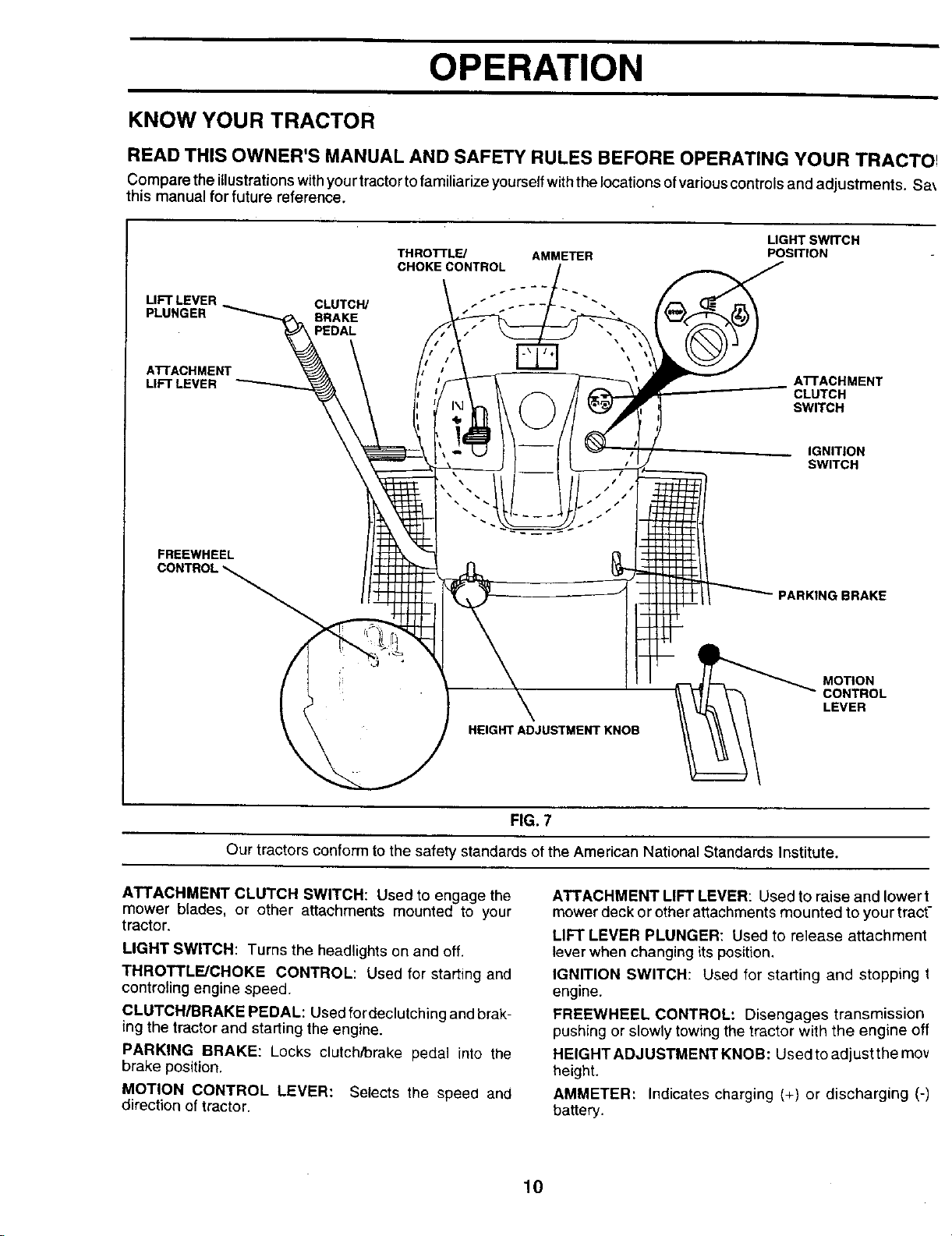
KNOW YOUR TRACTOR
READ THIS OWNER'S MANUAL AND SAFETY RULES BEFORE OPERATING YOUR TRACTOI
Compare the illustrationswithyourtractortofamiliarize yourseffwiththelocationsofvariouscontrolsand adjustments. Sa_
this manual for future reference.
LIFT LEVER. CLUTCH/
PLUNGER BRAKE
PEDAL
THROTrL_ AMMETER
CHOKE CONTROL
LIGHTSW_CH
POS_ION
ATrACHMENT
LIFT LEVER
AI-rACHMENT
CLUTCH
SWITCH
IGNITION
SWITCH
FREEWHEEL
PARKING BRAKE
L
HEIGHT ADJUSTMENT KNOB
MOTION
CONTROL
LEVER
FIG. 7
Our tractors conform to the safety standards of the American National Standards Institute.
ATTACHMENT CLUTCH SWITCH: Used to engage the
mower blades, or other attachments mounted to your
tractor.
LIGHT SWITCH: Turns the headlights on and off.
THROTTLE/CHOKE CONTROL: Used for starting and
controling engine speed.
CLUTCH/BRAKE PEDAL: Used fordeclutching and brak-
ing the tractor and starting the engine.
PARKING BRAKE: Locks clutch/brake pedal into the
brake position.
MOTION CONTROL LEVER: Selects the speed and
direction of tractor.
ATTACHMENT LIFT LEVER: Used to raise and lower t
mower deck or otherattachments mounted to your tract-
LIFT LEVER PLUNGER: Used to release attachment
lever when changing its position.
IGNITION SWITCH: Used for starting and stopping t
engine.
FREEWHEEL CONTROL: Disengages transmission
pushing or slowly towing the tractor with the engine off
HEIGHT ADJUSTMENT KNOB: Used to adjustthe mov
height.
AMMETER: Indicates charging (+) or discharging (-)
battery.
10
OPERATION
The operation of any tractor can result in foreign objects thrown into the eyes, which
can result in severe eye damage. Always wear safety glasses or eye shields while
operating your tractor or performing any adjustments or repairs. We recommend a wide
vision safety mask over the spectacles or standard safety glasses.
HOW TO USE YOUR TRACTOR
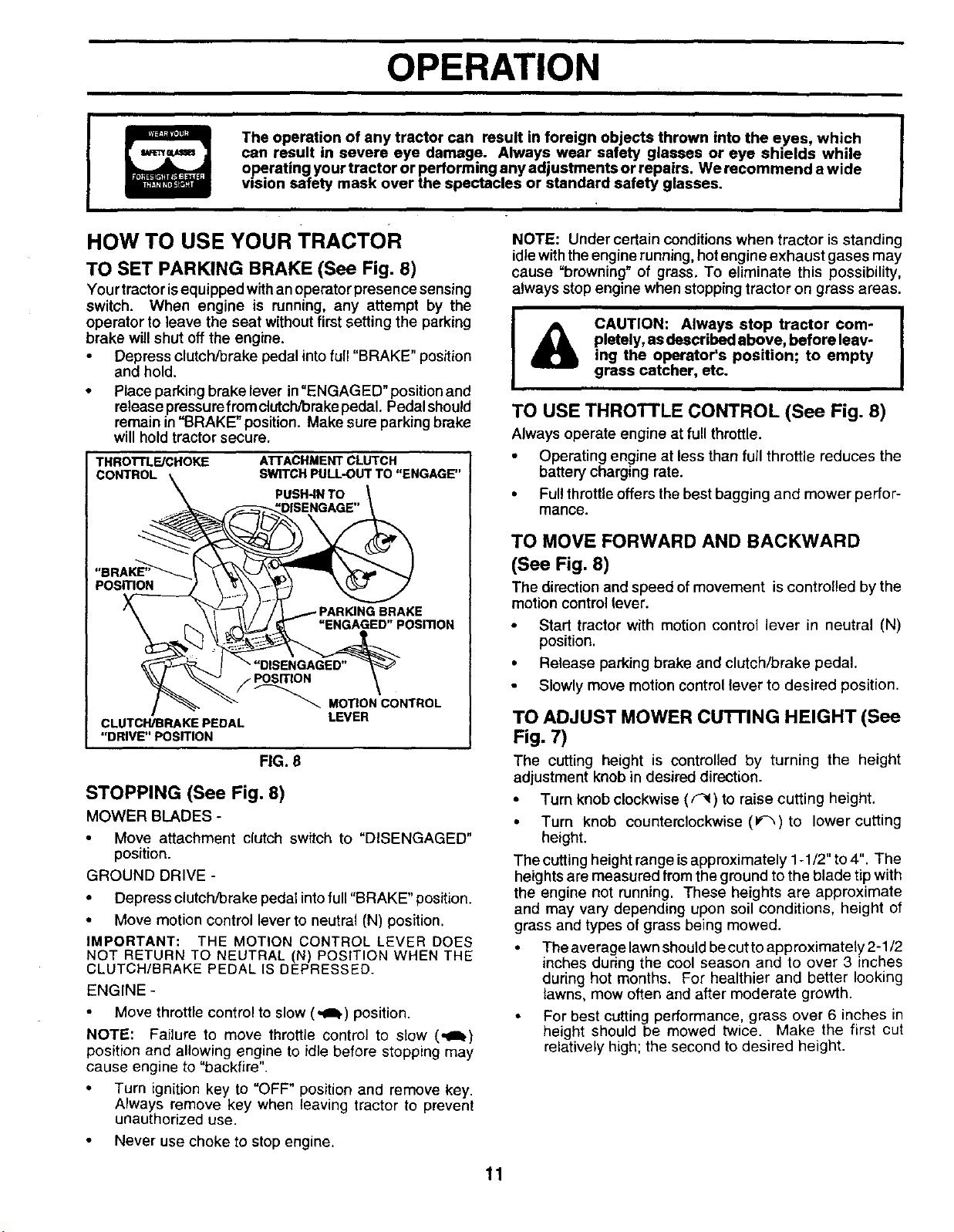
TO SET PARKING BRAKE (See Fig. 8)
Your tractor isequipped withan operator presence sensing
switch. When engine is running, any attempt by the
operator to leave the seat without first setting the parking
brake will shut off the engine.
• Depress clutch/brake pedal intofull "BRAKE" position
and hold.
• Place parking brake lever in "ENGAGED" position and
release pressure from clutch/brake pedal. Pedal should
remain in "BRAKE" position. Make sure parking brake
will hold tractor secure.
THROTTL_CHOKE
CONTROL
ATrACHMENTCLUTCH
SWITCH PULL-OUTTO"ENGAGE"
PUSH-IN TO
PosmoN
"ENGAGED"POSmON
F
MOTION CONTROL
CLUTCH/BRAKE PEDAL LEVER
"DRIVE" POSITION
FIG. 8
STOPPING (See Fig. 8)
MOWER BLADES-
Move attachment clutch switch to "DISENGAGED"
position.
GROUND DRIVE -
• Depress clutch, brake pedal into full "BRAKE" position.
• Move motion control lever to neutral (N) position.
IMPORTANT: THE MOTION CONTROL LEVER DOES
NOT RETURN TO NEUTRAL (N) POSITION WHEN THE
CLUTCH/BRAKE PEDAL IS DEPRESSED.
ENGINE -
Move throttle control to slow (_) position.
NOTE: Failure to move throttle control to slow (,qlh)
position and allowing engine to idle before stopping may
cause engine to "backfire".
• Turn ignition key to "OFF" position and remove key.
Always remove key when leaving tractor to prevent
unauthorized use.
• Never use choke to stop engine.
NOTE: Under certain conditionswhen tractor is standing
idlewiththe engine running, hot engine exhaust gases may
cause "browning" of grass. To eliminate this possibility,
always stop engine when stopping tractor on grass areas.
I
I
CAUTION: Always stop tractor com- I
pletely, as described above, before leav-
I
ing the operator's position; to empty
grass catcher, etc.
TO USE THROTTLE CONTROL (See Fig. 8)
Always operate engine at full throttle.
• Operating engine at less than full throttle reduces the
battery charging rate.
• Ful! throttle offers the best bagging and mower perfor-
mance.
TO MOVE FORWARD AND BACKWARD
(See Fig. 8)
The directionand speed of movement is controlled by the
motion control lever.
• Start tractor with motion control lever in neutral (N)
position.
• Release parking brake and clutch/brake pedal.
Slowly move motion control lever to desired position.
TO ADJUST MOWER CUTTING HEIGHT (See
Fig. 7)
The cutting height is controlled by turning the height
adjustment knob in desired direction.
• Turn knob clockwise ((q() to raise cutting height,
• Turn knob counterclockwise (_,)to lower cutting
height.
The cutting height range is approximately 1-1/2" to 4". The
heights are measured from the ground to the blade tip with
the engine not running. These heights are approximate
and may vary depending upon soil conditions, height of
grass and types of grass being mowed.
• The average lawn should be cut to app roximately 2-1/2
inches during the cool season and to over 3 inches
during hot months. For healthier and better looking
lawns, mow often and after moderate growth.
For best cutting performance, grass over 6 inches in
height should be mowed twice. Make the first cut
relatively high; the second to desired height.
11
OPERATION
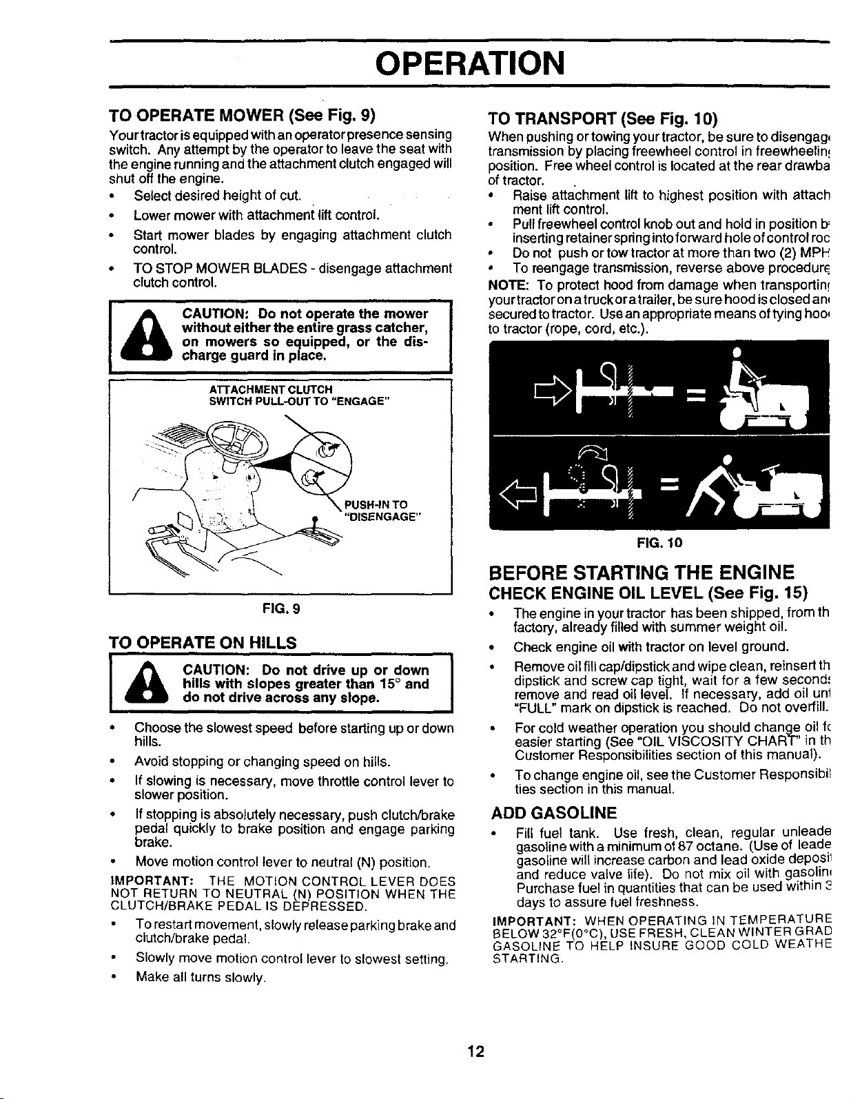
TO OPERATE MOWER (See Fig, 9)
Yourtractorisequipped with an operatorpresence sensing
switch. Any attempt by the operatorto leave the seat with
the engine runningand the attachment clutch engaged will
shut off the engine.
• Select desired height of cut.
• Lower mower with attachment lift control.
Start mower blades by engaging attachment clutch
contml.
• TO STOP MOWER BLADES - disengage attachment
clutch control.
CAUTION: Do not operate the mower
without either the entire grass catcher,
on mowers so equipped, or the dis-
charge guard in place.
A'I-rACHMENT CLUTCH
SWITCH PULL-OUT TO "ENGAGE"
FIG, 9
TO OPERATE ON HILLS
I _ CAUTION: Do not drive up or down ]
hills with slopes greater than 15° and
do not drive across any slope.
• Choose the slowest speed before starting up or down
hills.
• Avoid stopping or changing speed on hills.
• If slowing is necessary, move throttle control lever to
slower position.
• If stopping is absolutely necessary, push clutch/brake
pedal quickly to brake position and engage parking
brake.
Move motion control lever to neutral (N) position,
IMPORTANT: THE MOTION CONTROL LEVER DOES
NOT RETURN TO NEUTRAL (N) POSITION WHEN THE
CLUTCH/BRAKE PEDAL IS DEPRESSED.
To restart movement, slowly re{ease parking brake and
clutch/brake pedal.
Slowly move motion control lever to slowest setting.
Make all turns slowly.
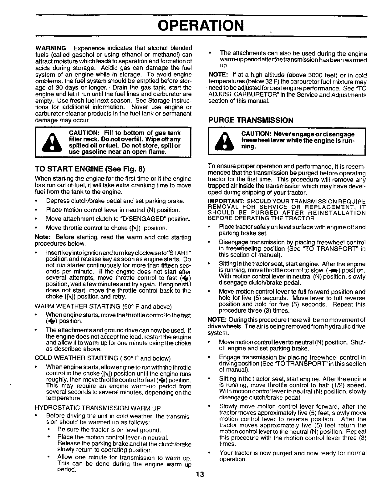
TO TRANSPORT (See Fig. 10)
When pushing or towing yourtractor, be sure to disengagq
transmission by placing freewheel control in freewheelin!
position. Free wheel control is located at the rear drawba
of tractor.
* Raise attachment lift to highest position with attach
ment lift control.
• Pull freewheel control knob out and hold in position b_
inserting retainer spring intoforward hole ofcontrol roc
• Do not push or tow tractorat more than two (2) MPt_
o To reengage transmission, reverse above procedur_
NOTE: To protect hoodfrom damage when transportin!
your tractoron atruckor atrailer, be sure hood isclosedan_
secured totractor. Use anappropriate means oftyinghoo_
to tractor(rope, cord, etc.).
FIG. 10
BEFORE STARTING THE ENGINE
CHECK ENGINE OIL LEVEL (See Fig. 15)
• The engine in yourtractor has been shipped, from th
factory, already filled with summer weight oil.
• Check engine oil with tractor on level ground.
• Remove oilfill cap/dipstickand wipe clean, reinsert th
dipstick and screw cap tight, wait for a few second'
remove and read oil level. If necessary, add oil unl
"FULL" mark on dipstick is reached. Do not overfill.
• For cold weather operation you should change oil f(
easier starting (See "OIL VISCOSITY CHART" in th
Customer Responsibilities section of this manual).
• To change engine oil, see the Customer Responsibil
ties section in this manual.
ADD GASOLINE
Fill fuel tank. Use fresh, clean, regular unleade
gasolinewith a minimumof87 octane. (Use of leade
gasoline willincrease carbon and lead oxide deposil
and reduce valve life). Do not mix oil with gasolin_
Purchase fuel in quantities that can be used within 3
days to assure fuel freshness.
IMPORTANT: WHEN OPERATING IN TEMPERATURE
t3ELOW32°F(0°C), USE FRESH, CLEAN WINTER GRAD
GASOLINE TO HELP INSURE GOOD COLD WEATHE
STARTING.
12
OPERATION
WARNING: Experience indicates that alcohol blended
fuels (called gasohol or using ethanol or methanol) can
attract moisture which leads toseparation and formation of
acids during storage. Acidic gas can damage the fuel
system of an engine while in storage. To avoid engine
problems, the fuel system should be emptied before stor-
age of 30 days or longer.- Drain the gas tank, start the
engine and let itrun untilthe fuel lines and carburetor are
empty. Use fresh fuel next season. See Storage Instruc-
tions for additional information. Never use engine or
carburetor cleaner products in the fuel tank or permanent
damage may occur.
I
&
CAUTION: Fill to bottom of gas tank I
filler neck. Do not overfill. Wipe off any
I
spilled oil or fuel. Do not store, spill or
use gasoline near an open flame.
TO START ENGINE (See Fig. 8)
When starting the engine for the first time or if the engine
has run out of fuel, it will take extra cranking time to move
fuel from the tank to the engine.
Depress clutch/brake pedal and set parking brake.
Place motion control lever in neutral (N) position.
• Move attachment dutch to "DISENGAGED" position.
• Move throttle control to choke (N) position.
Note: Before starting, read the warm and cold starting
procedures below.
Insert key into ignition and turn key clockwise to"START"
position and release key as soon as engine starts. Do
not run starter continuously for more than fifteen sec-
onds per minute. If the engine does not start after
several attempts, move throttle control to fast (,_)
position,wait afew minutes and try again. Ifengine still
does not start, move the throttle control back to the
choke (N) position and retry.
WARM WEATHER STARTING (50° F and above)
• When engine starts, move the throttle control to the fast
(,,_) position.
The attachments and ground drive can now be used. If
the engine does not accept the load, restart the engine
and allow it to warm up for one minute using the choke
as described above.
COLD WEATHER STARTING ( 50° F and below)
• When engine starts, allowengine to run with the threttle
control in the choke (N) position until the engine runs
roughly, then move throttle control to fast (,_) position.
This may require an engine warm-up period from
several seconds to several minutes, depending on the
temperature.
HYDROSTATIC TRANSMISSION WARM UP
• Before driving the unit in cold weather, the transmis-
sion should be warmed up as follows:
Be sure the tractor is on level ground.
• Place the motion control lever in neutral
Release the parking brake and let the clutch/brake
slowly return to operating position.
Allow one minute for transmission to warm up.
This can be done during the engine warm up
period.
The attachments can also be used during the engine
warm-up period afterthetransmisslen has been warmed
up.
NOTE: If at a high altitude (above 3000 feet) or in cold
temperatures (below 32 F) the carburetor fuel mixture may
need tobeadjusted for best engine performance. See "TO
ADJUST CARBURETOR" inthe Service and Adjustments
section of this manual.
PURGE TRANSMISSION
I _ CAUTION: Neverengageordisengage I
f.reewheal lever while the engine is run-
ning.
To ensure proper operation and performance, it is recom-
mended that the transmission be purged before operating
tractor for the first time. This procedure will remove any
trapped air insidethe transmission which may have devel-
oped during shippingof your tractor.
IMPORTANT: SHOULD YOUR TRANSMISSION REQUIRE
REMOVAL FOR SERVICE OR REPLACEMENT, IT
SHOULD BE PURGED AFTER REINSTALLATION
BEFORE OPERATING THE TRACTOR.
• Place tractor safely on level surface with engine off and
parking brake set.
Disengage transmission by placing freewheel control
in freewheeling position (See "TO TRANSPORT" in
this section of manual).
• Sittinginthetractorseat, startengine. After the engine
is running, move throttle control to slow (-Ib) position.
With motion control lever in neutral (N) position, slowly
disengage clutch/brake pedal.
Move motion control lever to full forward position and
hold for five (5) seconds. Move lever to full reverse
position and hold for five (5) seconds. Repeat this
procedure three (3) times.
NOTE: Duringthisprocedure there willbe no movement of
drivewheels. The air isbeing removed from hydraulic drive
system.
Move motioncontrollever toneutral (N) position. Shut-
offengine and set parking brake.
• Engage transmission by placing freewheel control in
drivingposition(See "TO TRANSPORT" inthis section
of manual).
• Sittinginthetractor seat, start engine. After the engine
is running, move threttle control to half (1/2) speed.
With motioncentre1lever inneutral (N) position, slowly
disengage clutch/brake pedal.
Slowly move motion control lever forward, after the
tractormoves approximately five (5) feet, slowly move
motion control lever to reverse position. After the
tractor moves approximately five (5) feet return the
motion control lever to the neutral (N) position. Repeat
this procedure with the motion control lever three (3)
times.
Your tractor is now purged and now ready for normal
operation.
13
OPERATION
MOWING TIPS MULCHING MOWING TIPS
Tire chains cannot be used when the mower housing
is attached to tractor,
• Mower should be properly leveled for best mowing
performance. See "TO LEVEL MOWER HOUSING" in
the Service and Adjustments section of this manual.
• The left hand side of mower should be used for trim-
ming.
Drive so that clippings are discharged onto the area
that has been cut. Have the cut area to the right of the
machine. This will result in a more even distribution of
clippings and more uniform cutting.
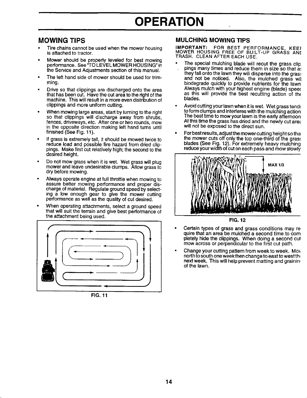
When mowing large areas, start by turning to the right
so that clippings will discharge away from shrubs,
fences, driveways, etc. After one or two rounds, mow
in the opposite direction making left hand turns until
finished (See Fig. 11).
• If grass is extremely tall, it should be mowed twice to
reduce load and possible fire hazard from dried clip-
pings. Make first cut relatively high; the second to the
desired height.
• Do not mow grass when it is wet. Wet grass will plug
mower and leave undesirable dumps. Allow grass to
dry before mowing.
Always operate engine at full throttle when mowing to
assure better mowing performance and proper dis-
charge of material. Regulate ground speed by select-
ing a low enough gear to give the mower cutting
performance as well as the quality of cut desired.
• When operating attachments, select a ground speed
that will suit the terrain and give best performance of
the attachment being used.
f
Ii
FIG. 11
IMPORTANT: FOR BEST PERFORMANCE, KEE!:
MOWER HOUSING FREE OF BUILT-UP GRASS AN[
TRASH. CLEAN AFTER EACH USE.
The special mulching blade will recut the grass clip
pings mariy times and reduce them in size so that a.'
they fall onto the lawn they wilt disperse into the gras.,
and not be noticed. Also, the mulched grass wi!
biodegrade quickly to provide nutrients for the lawn
Always mulch with your highest engine (blade) spee(
as this will provide the best recutting action of th_
blades.
Avoidcutting your lawn when it iswet. Wet grass tend.'
toform clumps and interferes with the mulching action
The best time to mow your lawn is the early afternoon
At this time the grass has dried and the newly cut ares
will not be exposed to the direct sun.
For best results, adjust the mower cutting height so tha
the mower cuts off only the top one-third of the gras,
blades (See Fig. 12). For extremely heavy mulching
reduce your width of cut on each pass and mow slowly
MAX 1/3
FIG. 12
Certain types of grass and grass conditions may re
quire that an area be mulched a second time to corn
pletely hide the clippings. When doing a second cul
mow across or perpendicular to the first cut path.
Change your cuttingpattern from week to week. Mo_
north tosouthone week then change toeast towest th,
next week. This willhelp prevent matting and grainin,
of the lawn.
14
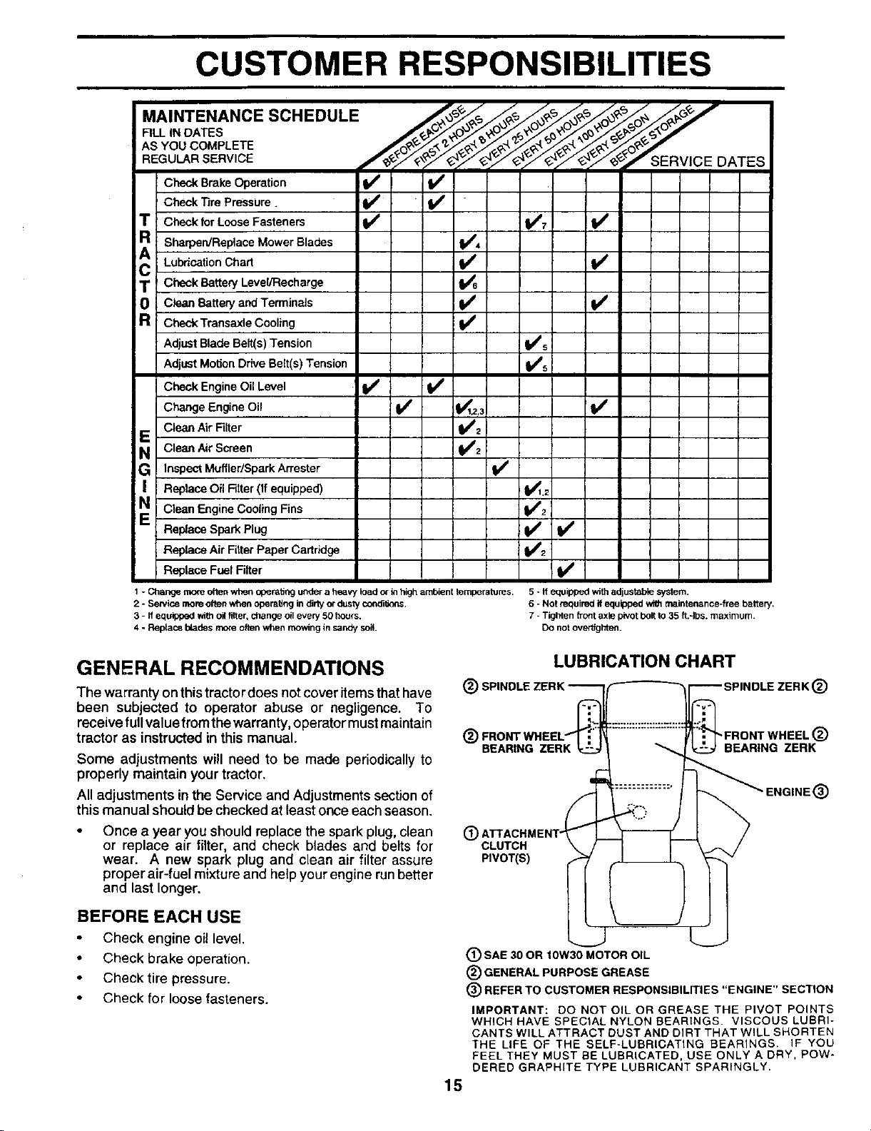
CUSTOMER RESPONSIBILITIES
....
AS YOU COMPLETE
REGU RSERWCE 'S - y 2"SEnVlCEDATES
Check Brake Operation _ _V'
Check Tire Pressure.
T Check for Loose Fasteners I_ re7 t#4
R
SharpelVReplace Mower Blades V'4
A Lubrication Chad If
T Check Battery Level/Recharge
Clean Battery and Terminals I##
R Check Transaxle Cooling
Adjust Blade Belt(s) Tension I##s
Adjust Motion Drive Belt(s) Tension I_#s
Check Engine Oil Level V'
Change Engine Oil If I_1.z,3 V'
Clean Air Filter _t_12
E Clean Air Screen
G !Inspect Muffler/Spark Arrester
| I Replace Oil Filter (If equipped) t1_.2
N I Clean Engine Cooling Fins _i
Replace Spark Plug ll/
Replace Air Fitter Paper Cartridge
i Replace Fuel Filter V'
1 - Change two_eoften when op_ratti_ under a heavy load o_in high ambient temperatures,
2 - Sentloe more often when operating in dirty_ dustycondi6ons.
3 - If equipped withoil fitter, change oil every 50 hours.
4 - Reptace blades more often when mowing in sandy soil
5 - ff equipl_d with adjustable system.
6 - Not required If equipped with malotenance-free battery.
7 - Tighten front axle pivotbolt to35 ft.-Ibs, maximum.
Do nol overtighten.
GENERAL RECOMMENDATIONS
The warranty on thistractordoes not cover items that have (_
been subjected to operator abuse or negligence. To
receive full value from the warranty, operator must maintain
tractor as instructed in this manual. (_
Some adjustments will need to be made periodically to
properly maintain your tractor.
All adjustments in the Service and Adjustments section of
this manual should be checked at least once each season.
Once a year you should replace the spark plug, clean
or replace air filter, and check blades and belts for
wear. A new spark plug and clean air filter assure
proper air-fuel mixture and help your engine run better
and last longer.
BEFORE EACH USE
Check engine oil level.
• Check brake operation.
Check tire pressure.
Check for loose fasteners.
@
15
LUBRICATION CHART
®
BEARING ZERK
"FRONT WHEEL (_)
BEARING ZERK
®
CLUTCH
PIVOT(S)
(_) SAE 30 OR 10W30 MOTOR OIL
® GENERAL PURPOSE GREASE
® REFER TO CUSTOMER RESPONSIBILITIES "ENGINE" SECTION
IMPORTANT: DO NOT OIL OR GREASE THE PIVOT POINTS
WHICH HAVE SPECIAL NYLON BEARINGS, VISCOUS LUBRI-
CANTS WILL ATTRACT DUST AND DIRT THAT WiLL SHORTEN
THE LIFE OF THE SELF-LUBRICATING BEARINGS, iF YOU
FEEL THEY MUST BE LUBRICATED, USE ONLY A DRY, POW-
DERED GRAPHITE TYPE LUBRICANT SPARINGLY,

CUSTOMER RESPONSIBILITIES
TRACTOR
Always observe safety rules when performing any mainte-
nance.
BRAKE OPERATION
If tractor requires more than six (6) feet stopping distance
at high speed inhighest gear, then brake mustbe adjusted.
(See =TO ADJUST BRAKE" in the Service and Adjust-
mentssection ofthis manual).
TIRES
• Maintain proper air pressure in all tires (See =PROD-
UCT SPECIFICATIONS" on page 2 of this manual).
• Keep tires free ofgasoline, oil, or insect control chemi-
cals which can harm rubber.
• Avoid stumps, stones, deep ruts, sharp objects and
other hazards that may cause tire damage.
BLADE CARE
For best results mower blades must be kept sharp. Re-
place bent or damaged blades.
BLADE REMOVAL (See Fig. 13)
• Raise mower to highest position to allow access to
blades.
• Remove hex bolt, Iockwasher and flat washer securing
blade.
• Install new or resharpened blade with trailing edge up
towards deck as shown.
Reassemble hex bolt, lock washer and flat washer in
exact order as shown.
Tighten bolt securely (30-35 Ft. Lbs. torque).
IMPORTANT: BLADE BOLT IS GRADE 8 HEATTREATED.
NOTE: We do notrecommend sharpening blade -but ifyou
do, be sure the blade is balanced.
BLADE _ MANDREL
\ _ ASSEMBLY
T.A,'INGEOGE
LOCKWASHER I
I
*A GRADE 8 HEAT TREATED BOLT CAN BE
IDENTIFIED BY SIX LINES ON THE BOLT HEAD.
TO SHARPEN BLADE (See Fig. 14)
Care should be taken to keep the blade balanced. An
unbalanced bladewillcause excessive vibration and even-
tual damage to mower and engine.
The bladepan be sharpened with a file or on a gdnding
wheel. Do notattempt tosharpen while on the mower.
• To check blade balance, you will need a 5/8" diameter
steelbolt, pin,or a cone balancer. (When using a cone
balanoer, fotiow the instructions supplied with bal-
ancer).
Slide blade on to an unthreaded portion of the steel bolt
or pin and hold the bolt or pin parallel with the ground.
If blade is balanced, it should remain in a horizontal
position. If either end of the blade moves downward,
sharpen the heavy end until the blade is balanced.
NOTE: Do not use a nail for balancing blade. The lobes of
the center hole may appear to be centered, but are not.
CENTER HOLE
BLADE
RG. 14
BATI'ERY
Your tractor has a battery charging system which is suffi-
cient for normal use. However, periodic charging of the
battery with an automotive charger wifl extend its life.
Keep battery and terminals clean.
• Keep battery bolts tight.
Keep small vent holes open.
Recharge at 6-10 amperes for 1 hour.
TO CLEAN BATI'ERY AND TERMINALS
Corrosion and dirt on the battery and terminals can caus_
the battery to "leak" power.
• Open battery box door.
Disconnect BLACK battery cable first then REE
battery cable and remove battery from tractor.
Rinse the battery with plain water and dry.
Clean terminals and battery cable ends with wire
brush until bright.
Coat terminals with grease or petroleum jelly.
Reinstall battery (See "CONNECT BATTERY" in th(
Assembly section of this manual).
FIG. 13
16
CUSTOMER RESPONSIBILITIES
V-BELTS Change the oil after the first two hours of operation and
Check V-belts for deterioration and wear after 100 hoursof
operation and reptace if necessary. The belts are not
adjustable. Replace belts if they begin to slip from wear.
TRANSAXLE COOLING .
The fan and cooling fins of transmission should be kept
clean to assure proper cooling.
every 50 hours thereafter or at least once a year if the
tractor is not used for 50 hours in one year.
Check the crankcase oil level before starting the engine
and after each eight (8) hours of operation. Tighten oil fill
•cap/dipstick securely each time you check the oil level.
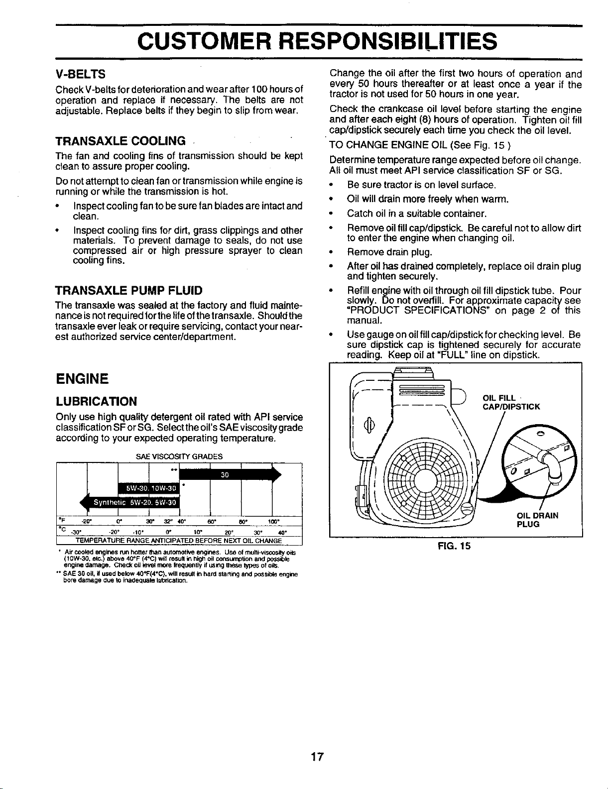
TO CHANGE ENGINE OIL (See Fig. 15 )
Determine temperature range expected before oil change.
All oil must meet API service classification SF or SG.
Do not attempt to clean fan or transmission while engine is
running or while the transmission is hot.
• Inspect cooling fan to be sure fan blades are intact and
clean.
Inspect cooling fins for dirt, grass clippings and other
materials. To prevent damage to seals, do not use
compressed air or high pressure sprayer to clean
coolingfins.
TRANSAXLE PUMP FLUID
The transaxle was sealed at the factory and fluid mainte-
nance isnot requiredlor tbelife ofthe transaxle. Shouldthe
transaxle ever leak or requireservicing, contact yournear-
est authorized service center/department.
ENGINE
LUBRICATION
Only use high quality detergent oil rated with API service
classification SFor SG. Select the oil's SAE viscosity grade
according to your expected operating temperature.
SAE VISCOSITY GRADES
I
°F -20° O" 30 ° 32 _ 40' 60• 80 _ 100°
°C .30° .20 ° .10 • 0° 10• 20 ° 30 ° 40_
TEMPERATURE RANGE ANTICIPATED BEFORE NEXT OIL CHANGE
• Air _ engines run hotterthan automotP_e engines. Use ofmulti-visoosityoils
(10W*30, elc.) above 40°F (4°C) win _esuif in high oilconsurnpf_onand possible
engine _amage. Ct-,ec_oiltevel mo_e frequenUy_fusingthese lypes of oils.
*• SAE 30 oil, ifused below40°F(4°C). will resultin hard startingand possible engine
bore damage due to inadequate lubrication.
• Be sure tractor is on level surface.
• Oil will drain more freely when warm.
• Catch oil in a suitable container.
Remove oil fill cap/dipstick. Be careful not to allow dirt
to enter the engine when changing oil.
Remove drain plug.
After oil has drained completely, replace oil drain plug
and tighten securely.
Refill engine with oil through oil fill dipstick tube. Pour
slowly. Do not overfill. For approximate capacity see
=PRODUCT SPECIFICATIONS" on page 2 of this
manual.
• Use gauge on oil fill cap/dipstick for checking level. Be
sure dipstick cap is tightened securely for accurate
reading. Keep oil at =FULL" line on dipstick.
OIL FILL
CAP/DIPSTICK
OIL DRAIN
PLUG
FIG. 15
17
CUSTOMER RESPONSIBILITIES
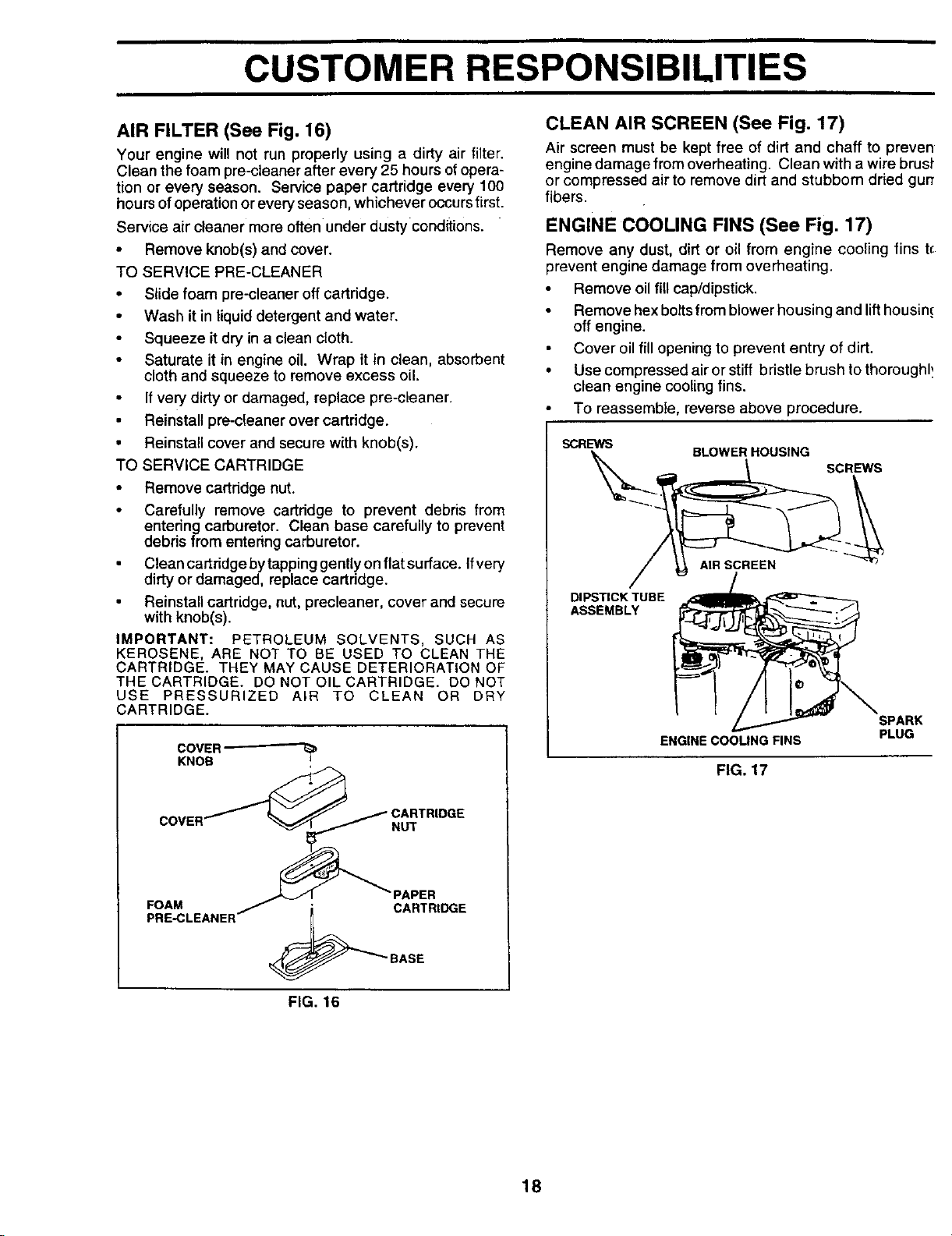
AIR FILTER (See Fig. 16)
Your engine will not run properly using a dirty air filter,
Clean the foam pre-cteaner after every 25 hours ofopera-
tion or every season. Service paper cartridge every 100
hours ofoperation or everyseason, whichever occursfirst.
Service air cleaner more often under dusty conditions.
• Remove knob(s) and cover.
TO SERVICE PRE-CLEANER
• Slide foam pre-cleaner offcartridge.
• Wash it in liquid detergent and water.
Squeeze it dry in a clean cloth.
• Saturate it in engine oil. Wrap it in clean, absorbent
cloth and squeeze to remove excess oil.
If very dirty or damaged, replace pre-cleaner.
• Reinstall pre-cleaner over cartridge.
• Reinstall cover and secure with knob(s).
TO SERVICE CARTRIDGE
• Remove cartridge nut.
Carefully remove cartridge to prevent debris from
entering carburetor. Clean base carefully to prevent
debris from entedng carburetor.
Clean cartridge by tapping gently on flat surface. Ifvery
dirty or damaged, replace cartridge.
Reinstall cartridge, nut, precleaner, cover and secure
with knob(s).
IMPORTANT: PETROLEUM SOLVENTS, SUCH AS
KEROSENE, ARE NOT TO BE USED TO CLEAN THE
CARTRIDGE. THEY MAY CAUSE DETERIORATION OF
THE CARTRIDGE. DO NOT OIL CARTRIDGE. DO NOT
USE PRESSURIZED AIR TO CLEAN OR DRY
CARTRIDGE.
COVER "_
KNOB
NUT
FOAM
PRE-CLEANER
PAPER
CARTRtDGE
BASE
CLEAN AIR SCREEN (See Fig. 17)
Air screen must be kept free of dirt and chaff to preven
engine damage from overheating. Clean with awirebrusP
or compressed air to remove dirt and stubbom dried gurr
fibers.
ENGINE COOLING FINS (See Fig. 17)
Remove any dust, dirt or eil from engine cooling fins t_
prevent engine damage from overheating.
Remove oil fill cab/dipstick.
Remove hex bolts from blower housing and lift housin.c
off engine.
Cover oil fill opening to prevent entry of dirt.
• Use compressed air or stiff bristle brush to thoroughl,.
clean engine cooling fins.
To reassemble, reverse above procedure.
SCREWS
BLOWERHOUSING
SCREWS
DIPSTICK TUBE
ASSEMBLY
ENGINE COOLING FINS
SPARK
PLUG
FIG. 17
FIG. 16
18
CUSTOMER RESPONSIBILITIES
MUFFLER
Inspect and replace corroded mufflerand spark arrester(if
equipped) as itcould create a fire hazard and/or damage.
SPARK PLUGS
Replace spark plugs at the beginning of each mowing
season or after every 100 hours of operation, whichever
occurs first. Spark plug type and gap settingare shownin
"PRODUCT SPECIFICATIONS" on page 2 ofthismanual.
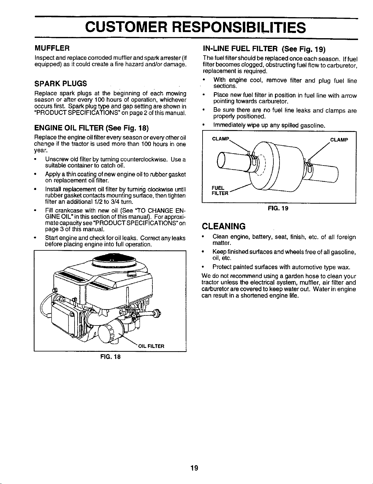
ENGINE OIL FILTER (See Fig. 18)
Replace the engine oilfilter every season or everyotheroil
change if the tractor is used more than 100 hours in one
year.
Unscrew oldfilter by turning counterclockwise. Use a
suitable container to catch oil.
• Apply a thin coating of new engine oil to rubber gasket
on replacement oil filter.
• Install replacement oil filter by tumirlg clockwise until
rubber gasket contacts mounting surface, then tighten
filter an additional 1/2 to 3/4 turn.
Fill crankcase with new oil (See "TO CHANGE EN-
GINE OIL" in this section of this manual). For approxi-
mate capacity see "PRODUCT SPECIFICATIONS" on
page 3 of this manual.
Start engine and check for oil leaks. Correct any leaks
before placing engine into full operation.
IN-LINE FUEL FILTER (See Fig. 19)
The fuelfiltershoutdbe replaced once each season. Iffuel
filter becomes clogged, obstructing fuel flew to carburetor,
replacement is required.
• With engine cool, remove filter and plug fuel line
sections.
Place new fuel filter in position in fuel line with arrow
pointingtowards carburetor.
Be sure there are no fuel line leaks and clamps are
properly positioned.
Immediately wipe up any spilled gasoline.
CLAMP
FUEL
FIG, 19
CLEANING
• Clean engine, bakery, seat, finish, etc. of all foreign
matter.
• Keep finished surfaces and wheels free of all gasoline,
oil, etc.
• Protect painted surfaces with automotive type wax.
We do not recommend using a garden hose to clean your
tractor unless the electrical system, muffler, air filter and
carburetor are covered to keep water out. Water in engine
can result in a shortened engine life.
FIG. 18
19
SERVICE AND ADJUSTMENTS
CAUTION: BEFORE PERFORMING ANY SERVICE OR ADJUSTMENTS:
&
Depress clutch/brake pedal fully and set parking brake.
Place motion control lever in neutral (N) position.
Place attachment clutch in "DISENGAGED" position.
• Turn ignition key "OFF" and remove key.
• Make sure the blades and all moving parts have completely stopped.
• Disconnect spark plug wire from spark plug and place wire where it cannot come in contact with
plug.
TRACTOR
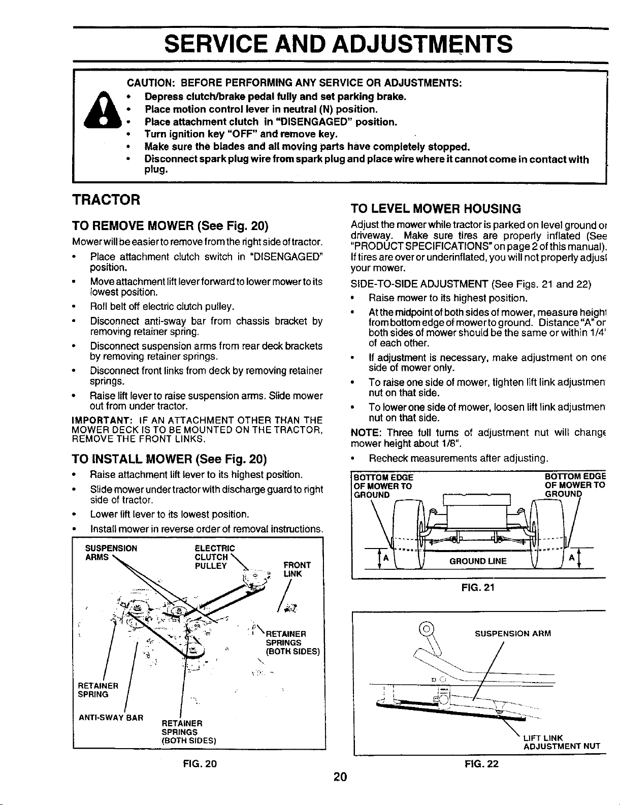
TO REMOVE MOWER (See Fig. 20)
Mower willbe easier toremove fromthe rightside oftractor.
Place attachment clutch switch in "DISENGAGED"
position.
• Move attachment lift leverforward to lowermower toits
lowest position.
Roll belt off electricdutch pulley.
Disconnect anti-sway bar from chassis bracket by
removing retainer spring.
• Disconnectsuspension arms from rear deckbrackets
by removing retainer springs.
• Disconnect front linksfrom deck by removing retainer
springs.
• Raise ift lever to raise suspension arms. Slide mower
out from under tractor.
IMPORTANT: IF AN ATTACHMENT OTHER THAN THE
MOWER DECK IS TO BE MOUNTED ON THE TRACTOR,
REMOVE THE FRONT LINKS.
TO INSTALL MOWER (See Fig. 20)
• Raise attachment lift lever to itshighest position.
Slide mower undertractorwithdischarge guardtoright
side of tractor.
Lower lift lever to its lowest position.
Install mower in reverse order of removal instructions.
SUSPENSION ELECTRIC
ARMS _ CLUTCH
PULLEY _,_ FRONT
.; i _ _ UNK
/t ¢ _'_ I_ SPRINGS
/ ._ _, _ _' (EOTBS_DES)
RETAINER
SPRING
..t
ANTI-SWAY BAR
RETAINER
SPRINGS
(BOTH SIDES)
TO LEVEL MOWER HOUSING
Adjust themower while tractor is parked on level ground ol
driveway. Make sure tires are properly inflated (See
"PRODUCT SPECIFICATIONS" on page 2 of this manual).
If tires are over or underinflated, you will not properly adjusl
your mower.
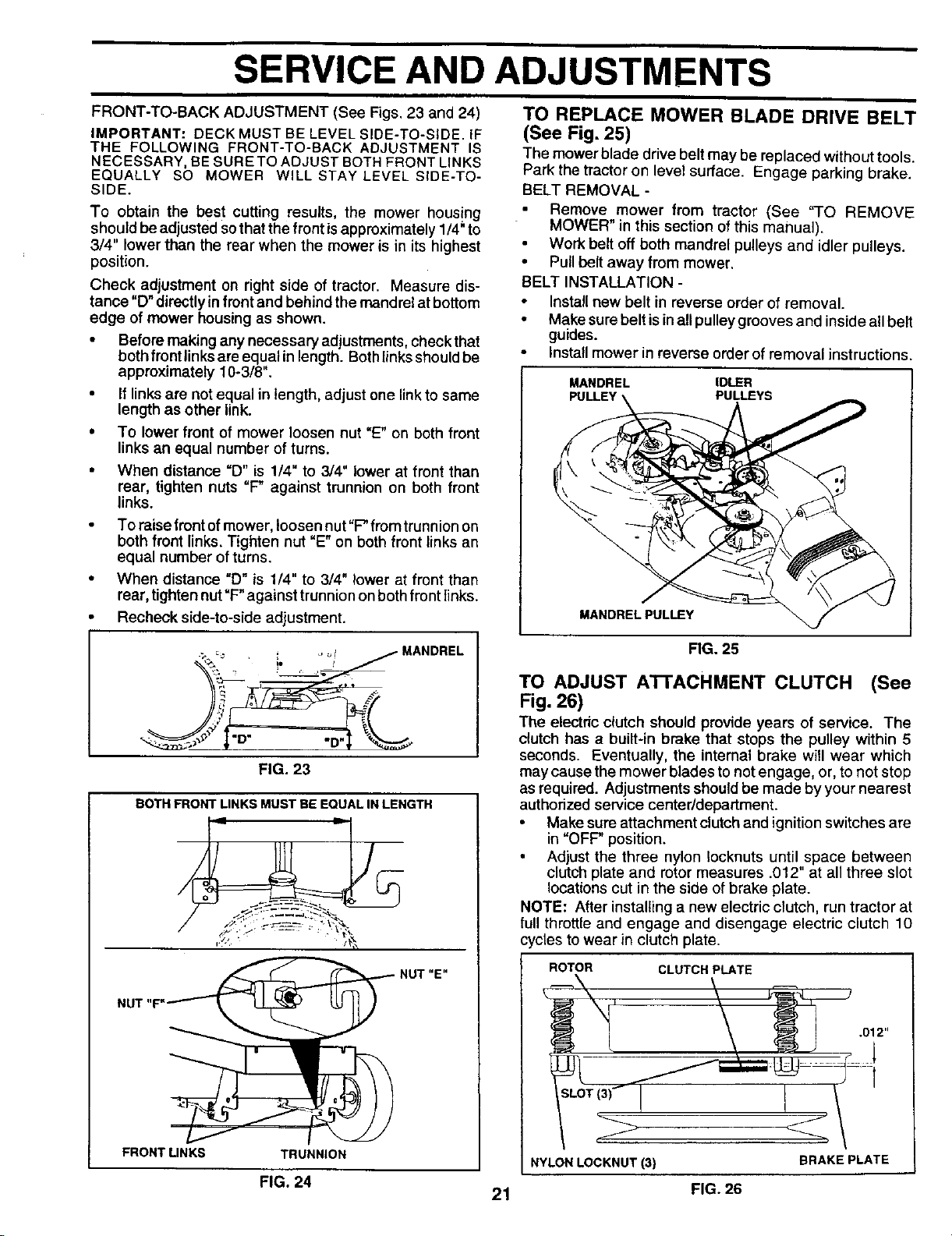
SIDE-TO-SIDE ADJUSTMENT (See Figs. 21 and 22)
• Raise mower to itshighest position.
Atthemidpoint ofboth sides ofmower, measure heighl
from bottomedge ofmower toground. Distance"A" or
both sides ofmower should be the same or within 1/4'
of each other.
If adjustment is necessary, make adjustment on on_
side of mower only.
To raise one side of mower, tighten lift link adjustmen
nut on that side.
• To lowerone side of mower, loosen lift link adjustmen
nut on that side.
NOTE: Three full turns of adjustment nut will chang_
mower height about 1/8".
• Recheck measurements after adjusting.
Bo'n'OM EDGE BO'I-rOM EDGE
OF MOWER TO OF MOWER TO
GROUND GROUND
FIG. 21
SUSPENSION ARM
i ;
j
LIFT LINK
ADJUSTMENT NUT
FIG. 20 FIG. 22
2O
SERVICE AND ADJUSTMENTS
FRONT-TO-BACK ADJUSTMENT (See Figs. 23 and 24)
IMPORTANT: DECK MUST BE LEVEL SIDE-TO-SIDE. IF
THE FOLLOWING FRONT-TO-BACK ADJUSTMENT IS
NECESSARY, BE SURETO ADJUST BOTH FRONT LINKS
EQUALLY SO MOWER WILL STAY LEVEL SIDE-TO-
SIDE.
To obtain the best cutting results, the mower housing
should be adjusted so that the front isapproximately 1/4_to
3/4" lower than the rear when the mower is in its highest
position.
Check adjustment on right side of tractor. Measure dis-
tance "D" directly infront and behind the mandrel at bottom
edge of mower housing as shown.
• Before making any necessary adjustments, check that
both front links are equal in length. Both links should be
approximately 10-3/8".
• If links are not equal in length, adjust one link to same
length as other link.
• To lower front of mower loosen nut =E"on both front
links an equal number of turns.
• When distance =D" is 1/4" to 3/4" lower at front than
rear, tighten nuts =F" against trunnion on both front
links.
To raise frontof mower, loosen nut "F" from trunnion on
both front links. Tighten nut "E" on both front links an
equal number of turns.
When distance "D" is 1/4" to 3/4" lower at front than
rear, tighten nut "F" against trunnion on both front links.
Recheck side-to-side adjustment.
MANDREL
>::: : _,o! /
J
FIG. 23
BOTH FRONT LINKS MUST BE EQUAL IN LENGTH
'4 .T-'
FRONT UNKS TRUNNION
FIG. 24
TO REPLACE MOWER BLADE DRIVE BELT
(See Fig. 25)
The mower blade drivebelt may be replaced without tools.
Park the tractor on level surface. Engage parking brake.
BELT REMOVAL -
Remove mower from tractor (See "TO REMOVE
MOWER" in this section of this manual).
Work belt off both mandrel pulleys and idler pulleys.
• Pull belt away from mower.
BELT INSTALLATION -
Install new belt in reverse order of removal.
Make sure belt is in all pulley grooves and inside all belt
guides.
Install mower in reverse order of removal instructions.
MANDREL IDLER
PULLEYS
21
MANDREL PULLEY
FIG. 25
TO ADJUST A'I-rACHMENT CLUTCH (See
Fig. 26)
The electric clutch should provide years of service. The
clutch has a built-in brake that stops the pulley within 5
seconds. Eventually, the internal brake will wear which
may cause the mower blades to not engage, or, to not stop
as required. Adjustments should be made by your nearest
authorized service center/department.
• Make sure attachment clutch and ignition switches are
in "OFP position.
• Adjust the three nylon locknuts until space between
clutch plate and rotor measures .012" at all three slot
locationscut in the side of brake plate.
NOTE: After installing a new electric clutch, run tractor at
full throttle and engage and disengage electric clutch 10
cycles to wear in clutch plate.
ROTOR CLUTCH PLATE
NYLON LOCKNUT (3) BRAKE PLATE
FIG. 26
i
SERVICE AND ADJUSTMENTS
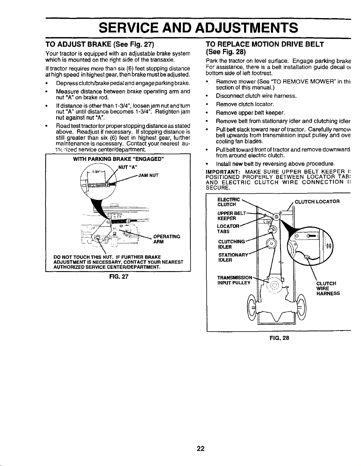
TO ADJUST BRAKE (See Fig. 27)
Your tractor is equipped with an adjustable brake system
which is mounted on the right side ofthe transaxie.
Iftractor requires more than six (6) feet stoppingdistance
at high speed inhighestgear,then brake mustbeadjusted.
• Depressclutch/brakepedalandengageparkingbrake,
Measure distance between brake operating arm and
nut "A" on brake rod.
If distance is other than 1-3/4", loosen jam nut and tum
nut "A" until distance becomes 1-3/4". Retighten jam
nut against nut =A".
Road test tractor for proper stopping distance asstated
above. Readjust if necessary. If stopping distance is
still greater than six (6) feet in highest gear, further
maintenance is necessary. Contact your nearest au-
_hc,rized service center/department.
WITH PARKING BRAKE "ENGAGED"
NUT "A"
OPERATING
ARM
DO NOT TOUCH THIS NUT. IF FURTHER BRAKE
ADJUSTMENT IS NECESSARY, CONTACT YOUR NEAREST
AUTHORIZED SERVICE CENTER/DEPARTMENT.
FIG. 27
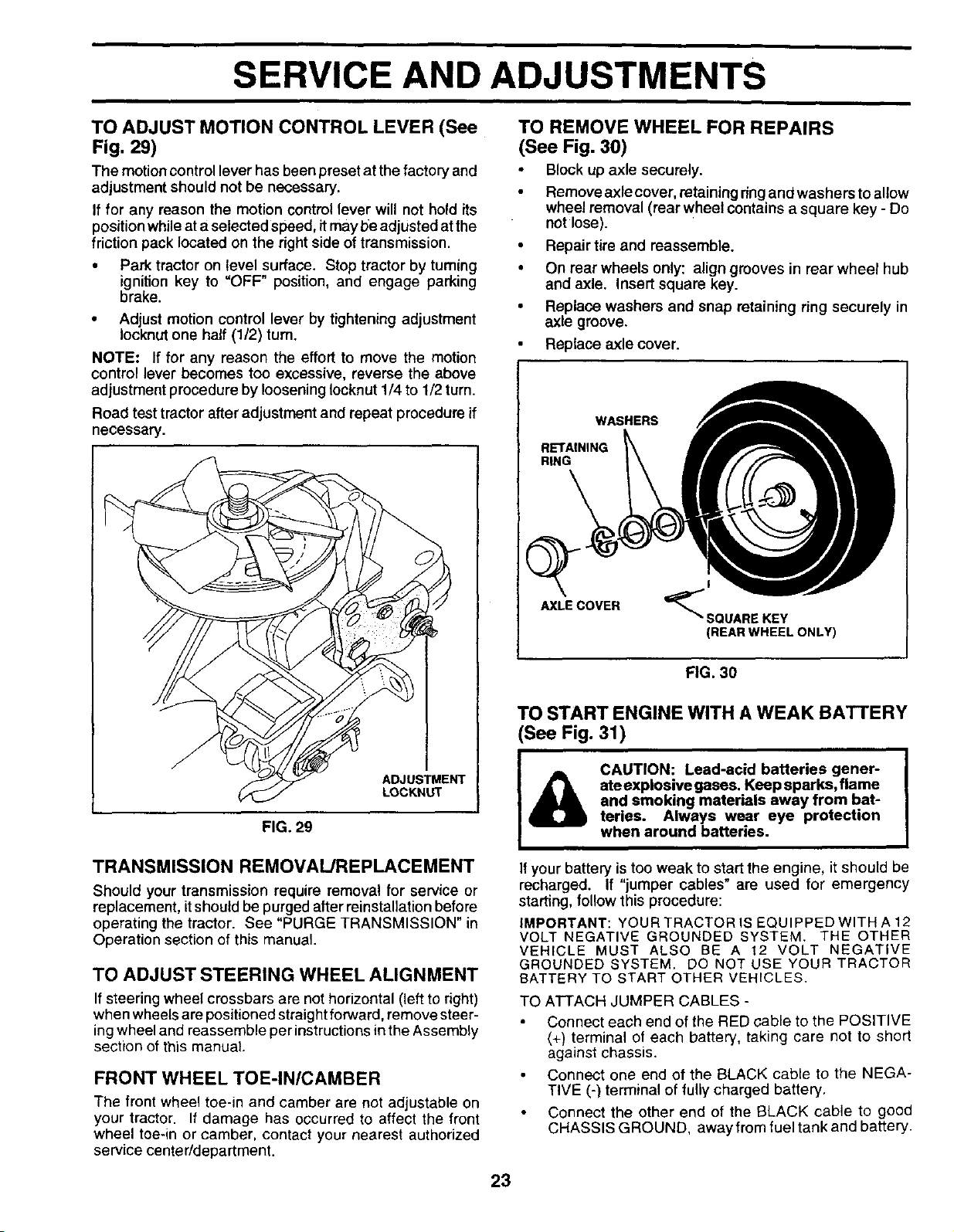
TO REPLACE MOTION DRIVE BELT
(See Fig. 28)
Park the tractor on level surface. Engage parking brake
For assistance, there is a belt installation guide decal o=
bottom side of left footrest.
• Remove mower (See "TO REMOVE MOWER" in thi:
section of this manual.)
Disconnect clutch wire harness.
Remove clutch Iocator.
• Remove upper belt keeper.
Remove belt from stationary idler and clutching idler
Pull belt slack toward rear of tractor. Carefully remow
belt upwards from transmission input pulley and ove
cooling fan blades.
• Pull belttoward front of tractor and remove downward:
from around electric clutch.
• Install new belt by reversing above procedure.
IMPORTANT: MAKE SURE UPPER BELT KEEPER I,'
POSITIONED PROPERLY BETWEEN LOCATOR TAB_
AND ELECTRIC CLUTCH WIRE CONNECTION I_
SECURE.
__ CLUTCHLOCATOR
UPPER BELT__]
KEEPER II
LOCATOR f II _ I
TABS
CLUTCHING_II ('_o_I _ I1:_\
" /___t
TRANSMISSION "_J_,_ f _._I _[ \
INPUTPULLEYIIJ"_?_ _'_ II CLUTCH
FIG. 28
22
SERVICE AND ADJUSTMENTS
TO ADJUST MOTION CONTROL LEVER (See
Fig. 29)
The motion control lever has been preset at the factory and
adjustment should not be necessary.
If for any reason the motion control lever will not hold its
position while at a selected speed, itmay be adjusted atthe
friction pack located on the right side of transmission.
• Park tractor on level surface. Stop tractor by turning
ignition key to =OFF" position, and engage parking
brake.
• Adjust motion control lever by tightening adjustment
Iocknut one half (1/2) tum.
NOTE: If for any reason the effort to move the motion
control lever becomes too excessive, reverse the above
adjustment procedure by loosening Iocknut 1/4 to 1/2 turn.
Road test tractor after adjustment and repeat procedure if
necessary.
ADJUSTMENT
LOCKNUT
FIG. 29
TRANSMISSION REMOVAL/REPLACEMENT
Should your transmission require removal for service or
replacement, it should be purged after reinstallation before
operating the tractor. See "PURGE TRANSMISSION" in
Operation section of this manual.
TO ADJUST STEERING WHEEL ALIGNMENT
If steering wheel crossbars are not horizontal (left to right)
when wheels are positioned straight forward, remove steer-
ing wheel and reassemble per instructions in the Assembly
section of this manual
FRONT WHEEL TOE-IN/CAMBER
The front wheel toe-in and camber are not adjustable on
your tractor. If damage has occurred to affect the front
wheel toe-in or camber, contact your nearest authorized
service center/department.
TO REMOVE WHEEL FOR REPAIRS
(See Fig. 30)
Block up axle securely.
Remove axle cover, retaining ring and washers to allow
wheel removal (rear wheel contains a square key - Do
not lose).
• Repair tire and reassemble.
• On rear wheels only: align grooves in rear wheel hub
and axle. Insert square key.
• Replace washers and snap retaining ring securely in
axle groove.
Replace axle cover.
WASHERS
RETAINING
RING
AXLE COVER
_SQUARE KEY
(REAR WHEEL ONLY)
FIG. 30
TO START ENGINE WITH A WEAK BATTERY
(See Fig. 31)
CAUTION: Lead-acid batteries gener-
ate explosive gases. Keep sparks, flame
and smoking materials away from bat-
teries. Always wear eye protection
when around batteries.
If your battery is too weak to start the engine, it should be
recharged. If "jumper cables" are used for emergency
starting, follow this procedure:
iMPORTANT: YOUR TRACTOR IS EQUIPPED WITH A 12
VOLT NEGATIVE GROUNDED SYSTEM. THE OTHER
VEHICLE MUST ALSO BE A 12 VOLT NEGATIVE
GROUNDED SYSTEM. DO NOT USE YOUR TRACTOR
BATTERY TO START OTHER VEHICLES.
TO ATTACH JUMPER CABLES -
Connect each end of the RED cable to the POSITIVE
(+) terminal of each battery, taking care not to short
against chassis.
Connect one end of the BLACK cable to the NEGA-
TIVE (-) terminal of fully charged battery.
Connect the other end of the BLACK cable to good
CHASSIS GROUND, away from fuel tank and battery.
23
SERVICE AND ADJUSTMENTS
INTERLOCKS AND RELAYS
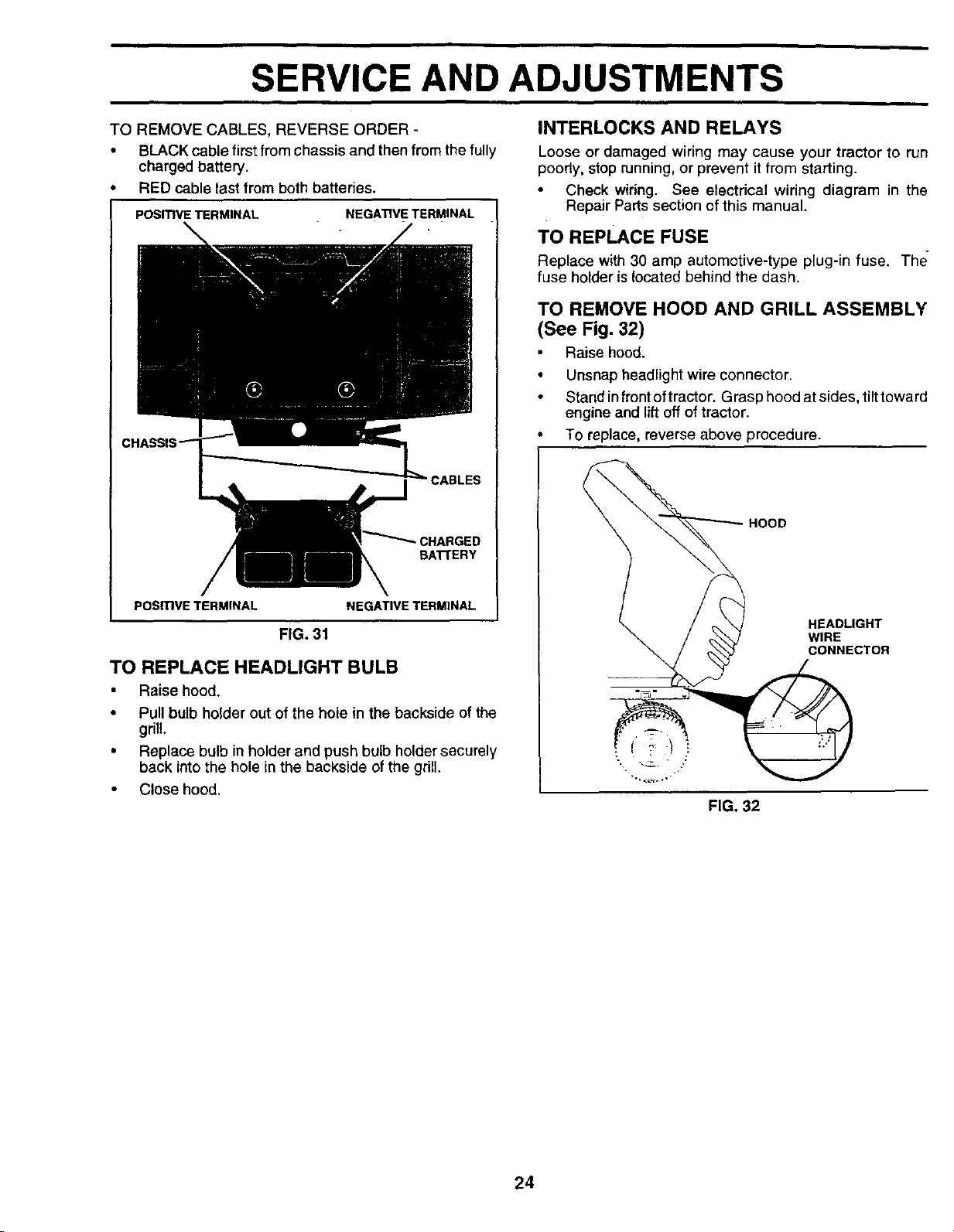
TO REMOVE CABLES, REVERSE ORDER -
• BLACK cable first from chassis and then from the fully
charged battery.
RED cable last from both batteries.
POSturETERMINAL
NEGATIVE TERMINAL
BATI'ERY
PosmvE TERMINAL NEGATIVE TERMINAL
FIG. 31
TO REPLACE HEADLIGHT BULB
• Raise hood.
• Pull bulb holder out of the hole in the backside of the
grill.
• Replace bulb in holder and push bulb holdersecurely
back intothe hole in the backside ofthe grill.
• Close hood.
Loose or damaged wiring may cause your tractor to run
poorly, stop running, or prevent it from starting.
Check wiring. See electrical wiring diagram in the
Repair Parts section of this manual.
TO REPLACE FUSE
Replace with 30 amp automotive-type plug-in fuse. The
fuse holderis located behind the dash.
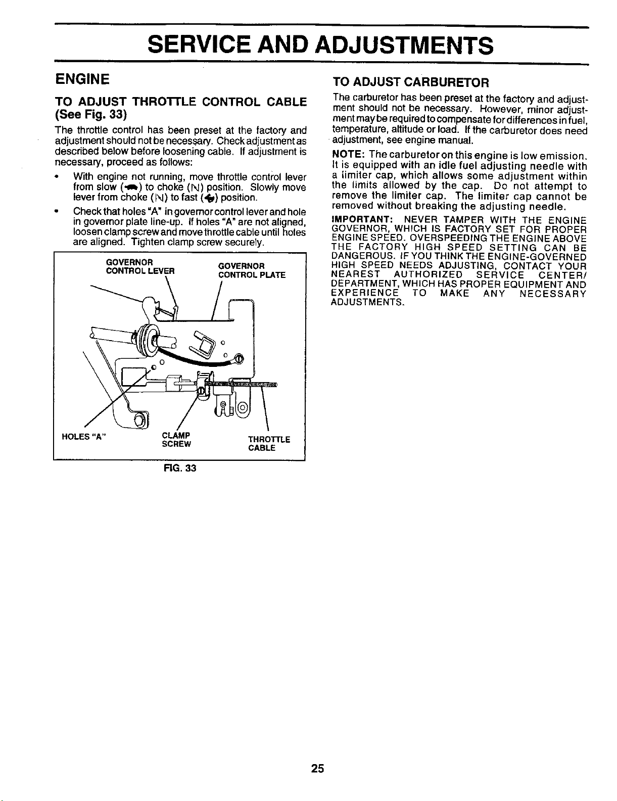
TO REMOVE HOOD AND GRILL ASSEMBLY
(See Fig. 32)
Raise hood.
• Unsnap headlight wire connector.
Stand in front oftractor. Grasp hood at sides, tilt toward
engine and lift off of tractor.
To replace, reverse above procedure.
HOOD
HEADLIGHT
WIRE
CONNECTOR
FIG. 32
24
SERVICE AND ADJUSTMENTS
ENGINE TO ADJUSTCARBURETOR
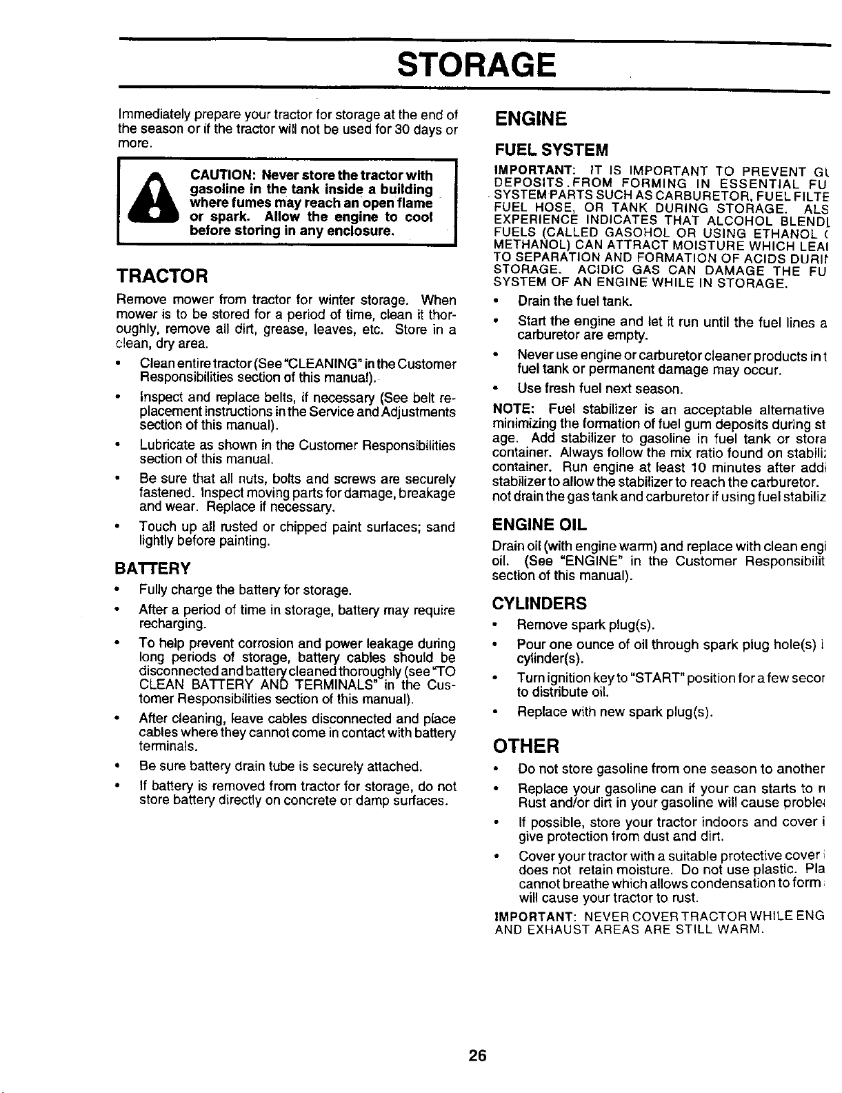
TO ADJUST THROTrLE CONTROL CABLE
(See Fig. 33)
The throttle control has been preset at the factory and
adjustment should not be necessary. Check adjustment as
described below before loosening cable. If adjustment is
necessary, proceed as follows:
• With engine not running, move throttle control lever
from slow (,=_) to choke (N) position. Slowly move
lever from choke (N) to fast (,¢ep)position.
• Check that holes "A" in governor control lever and hole
in governor plate line-up. If holes =A"are not aligned,
loosen clamp screw and move throttle cable until holes
are aligned. Tighten clamp screw securely.
GOVERNOR
CONTROL LEVER
GOVERNOR
CONTROL PLATE
HOLES "A"
CLAMP
SCREW
THROTrLE
CABLE
RG. 33
The carburetor has been preset at the factory and adjust-
ment should not be necessary. However, minor adjust-
ment may be required to compensate for differences infuel,
temperature, altitude or load. If the carburetor does need
adjustment, see engine manual.
NOTE: The carburetor on this engine is low emission.
It is equipped with an idle fuel adjusting needle with
a limiter cap, which allows some adjustment within
the limits allowed by the cap. Do not attempt to
remove the limiter cap. The limiter cap cannot be
removed without breaking the adjusting needle.
IMPORTANT: NEVER TAMPER WITH THE ENGINE
GOVERNOR, WHICH IS FACTORY SET FOR PROPER
ENGINE SPEED. OVERSPEEDING THE ENGINE ABOVE
THE FACTORY HIGH SPEED SETTING CAN BE
DANGEROUS. IF YOU THINK THE ENGINE-GOVERNED
HIGH SPEED NEEDS ADJUSTING, CONTACT YOUR
NEAREST AUTHORIZED SERVICE CENTER/
DEPARTMENT, WHICH HAS PROPER EQUIPMENT AND
EXPERIENCE TO MAKE ANY NECESSARY
ADJUSTMENTS.
25
STORAGE
ENGINE
Immediately prepare your tractor for storage at the end of
the season or if the tractor will not be used for 30 days or
more.
&
CAUTION: Never store the tractor with
gasoline in the tank inside a building
where fumes may reach an open flame
or spark. Allow the engine to cool
before storing in any enclosure.
TRACTOR
Remove mower from tractor for winter storage. When
mower is to be stored for a period of time, clean it thor-
oughly, remove all dirt, grease, leaves, etc. Store in a
clean, dry area.
• Clean entire tractor (See"CLEANING" inthe Customer
Responsibilities section of this manual).
Inspect and replace belts, if necessary (See belt re-
placement instructions in the Service and Adjustments
section of this manual).
Lubricate as shown in the Customer Responsibilities
section of this manual.
Be sure that all nuts, bolts and screws are securely
fastened. Inspect moving parts for damage, breakage
and wear. Replace if necessary.
Touch up all rusted or chipped paint surfaces; sand
lightly before painting.
BA'I-I'ERY
• Fully charge the battery for storage.
After a period of time in storage, battery may require
recharging.
• To help prevent corrosion and power leakage during
long periods of storage, battery cables should be
disconnected and battery cleaned thoroughly (see TO
CLEAN BATTERY AND TERMINALS" in the Cus-
tomer Responsibilities section of this manual).
• After cleaning, leave cables disconnected and place
cables where they cannot come in contact with battery
terminals.
• Be sure battery drain tube is securely attached.
• if battery is removed from tractor for storage, do not
store battery directly on concrete or damp surfaces.
FUELSYSTEM
IMPORTANT: IT IS IMPORTANT TO PREVENT G/
DEPOSITS.FROM FORMING IN ESSENTIAL FU
SYSTEM PARTS SUCH AS CARBURETOR, FUEL FILTE
FUEL HOSE, OR TANK DURING STORAGE. ALS
EXPERIENCE INDICATES THAT ALCOHOL BLEND[
FUELS (CALLED GASOHOL OR USING ETHANOL (
METHANOL) CAN ATTRACT MOISTURE WHICH LEAI
TO SEPARATION AND FORMATION OF ACIDS DURIt
STORAGE. ACIDIC GAS CAN DAMAGE THE FU
SYSTEM OF AN ENGINE WHILE IN STORAGE.
Drain the fuel tank.
Start the engine and let it run until the fuel lines a
carburetor are empty.
Never use engine or carburetor cleaner products in t
fuel tank or permanent damage may occur.
Use fresh fuel next season.
NOTE: Fuel stabilizer is an acceptable alternative
minimizing the formation of fuel gum deposits during st
age. Add stabilizer to gasoline in fuel tank or stora
container. Always follow the mix ratio found on stabili,
container. Run engine at least 10 minutes after addi
stabilizer to allow the stabilizer to reach the carburetor.
not drainthe gas tank and carburetor if using fuel stabiliz
ENGINE OIL
Drain oil (with engine warm) and replace with clean engi
oil. (See "ENGINE" in the Customer Responsibilit
section of this manual).
CYLINDERS
• Remove spark plug(s).
• Pour one ounce of oil through spark plug hole(s) i
cylinder(s).
Turn ignition key to "START" position for a few secor
to distribute oil.
Replace with new spark plug(s).
OTHER
Do not store gasoline from one season to another
Replace your gasoline can if your can starts to n
Rust and/or dirt in your gasoline will cause proble4
If possible, store your tractor indoors and cover i
give protection from dust and dirt.
Cover your tractor with a suitable protective cover
does not retain moisture. Do not use plastic. Pla
cannot breathe which allows condensation to form
will cause your tractor to rust.
IMPORTANT: NEVER COVER TRACTOR WHILE ENG
AND EXHAUST AREAS ARE STILL WARM.
26

TROUBLESHOOTING POINTS
CAUSE CORRECTION
PROBLEM
Will not start
Hard to start
Engine will not turn over
Engine clicks but will not
start
Loss of power
Excessive vibration
1. Out of fuel,
2, Engine not "CHOKED" propedy.
3. Engine flooded.
4. Bad spark plug.
5, Dirty air filter.
6. Dirty fuel filter.
7. Water in fuel.
8.
9.
Loose or damaged wiring.
Carburetor out of adjustment,
10. Eng{ne valves out of adjustment.
1, Dirty air filter,
2. Bad spark plug,
3. Weak or dead battery,
4. Dirty fuel fitter.
5, Stale or dirty fuel.
6. Loose or damaged wiring.
7. Carburetor out of adjustment.
8. Engine valves out of adjustment.
1. Diutch/brake pedal not depressed.
2. Attachment clutch is engaged.
3. Weak or dead battery.
4. Blown fuse.
5. Corroded battery terminals.
6. !.._e or damaged widng.
7. Faulty ignition switch.
8. Faulty solenoid or starter.
9. Faulty operator presence switch(es).
1. Weak or dead battery.
2. Corroded battery terminals.
3. Loose or damaged wiring.
4. Faulty solenoid or starter.
t. Curing too much grass/too fast.
2. Throttle in "CHOKE" position.
3. Build-up of grass, leaves and trash under mower.
4, Dirty air filter.
5 Low oil level/dirty oil.
6. Faulty spark plug.
7. Dirty fuel filter.
8. Stale or dirty fuel
9. Water in fuel,
10, Spark plug wire loose.
11. Dirty engine air screen/fins.
12. Dirty!clogged muffler.
t3. Loose or damaged wiring,
14. Carburetor out of adjustment.
t5. Engine valves out of adjustment.
1. Worn, bent or loose blade.
2 Bent blade mandrel.
3. Loose/damaged part(s)
1. Fill fuel tank.
2. See "TO START ENGINE" in Operation section.
3. .Wait several minutes before attempting to start.
4. Replace spark plug.
5. Clean/replace air filter.
6. Replace fuel filter.
7. Drain fuel tank and carburetor, refill tank with fresh
gasoline and replace fuel filter.
8. Check all wiring.
9. See "To Adjust Carburetor" in Service Adjustments
section.
10. Contact an authorized service center/department.
1. Cleanireplaca air filter.
2. Replace spark plug.
3. Recharge or replace battery.
4. Replace fuel tilter.
5. Drain fuel tank and refill with fresh gasoline.
6. Check all wiring.
7. See =To Adjust Carburetor" in Service Adjustments
section.
8. Contact an authorized service canter/department.
1. Depress dutch/brake pedal.
2. Disengage attachn_nt clutch.
3. Recharge or replace battery.
4. Replace fuse.
5. Clean battery terrdinais.
6. Check all wiring.
7. Check/replace ignition switch.
8, Check/replace solenoid or starter.
9. Contact an authorized service center/dapartmant.
t. Recharge or replace battery.
2. Clean battery terminals.
3. Check all wiring,
4 Check/replace solenoid or starter,
1. Set in "Higher Cut=position/reduce speed.
2. Adjust throttle control.
3. Clean underside of mower housing.
4. Cleaniraplace air filter,
5. Check oil level/change oil.
6. Clean and regap or change spark plug,
7. Replace fuel filter,
8. Drain fuel tank and refill with fresh gasoline.
9. Drain fuel tank and carburetor, refill tank with fresh
gasoline and replace fuel filter,
10. Connect and tighten spark plug wire.
11. Clean engine air screen/fins.
12. Cleanireplece muffler.
t3. Checkall wiring.
14. See =To Adjust Carburetor" in Service Adjustments
section.
15. Contact an authorized service center/department.
1. Replace blade. Tighten blade bolt.
2. Replace blade mandrel.
3. Tighten loose part(s). Replace damaged parts.
27

TROUBLESHOOTING POINTS
PROBLEM !CAUSE CORRECTION
Engine continues to run
when operator leaves seat
with attachment clutch
engaged
Poorcut-uneven
_._:__r blades will not
rotate
Poor grass discharge
Headlight(s) not working
(if so equipped)
Battery will not charge
Loss of drive
Engine "backfires"
when turning engine
"OFF"
1. Faulty operator-safety presence control system.
1.
2.
3.
4.
5.
6.
7.
8.
9.
10.
11.
1. Worn, bent or loose blade.
2. Mower deck not level.
3. Buildup of grass, leaves, and trash under mower.
4. Bent blade mandrel.
5. Clogged mower deck vent holes from buildup of
grass, leaves, and trash around mandrels.
1. Obstruction in clutch mechanism.
2. Worn/damaged mower dnve belt.
3. Frozen idler pulley.
4. Frozen blade mandrel.
1.
2.
3.
4.
5.
1,
2.
3.
4.
1. Check wiring, switches and connections. If not
corrected, contact an authorized service center/
department.
1,
2.
3.
1. Replace blade. Tighten blade bolt.
2. Level mower deck.
3. Clean underside of mower housing.
4. Replace blade mandrel.
5. Clean around mandrels to open vent holes.
1,
Engine speed too slow.
Travel speed too fast.
Wet grass.
Mower deck not level.
Low/uneven tire air pressure.
1. Remove obstruction.
2. Replace mower dnve belt.
3. Replace idler pullay.
4. Replace blade mandrel.
t. Place throttle control in =FAST" position.
2, Shift to slower speed.
3. Allow grass to dry before mowing.
4. Level mower deck.
5. Check fires for proper air pressure.
Worn, bent or loose blade. 6.
Buildup of grass, leaves and trash under mower. 7.
Mower drive belt worn. 8.
Blades improperly installed, 9.
Improper b_ades used. 10.
Clogged mower deck vent holes from buildup of 11.
grass, leaves, and trash around mandrels.
Switch is"OFF". 1.
Bulb(s) burned out. 2.
Faulty lightswitch. 3.
Loose or damaged widng. 4.
Blown fuse. 5.
Bad batte_ cell(s), t.
Poor cable connections. 2.
Faulty regulator (if so equipped). 3.
Faulty alternator. 4.
Freewheel control in =disengaged" position. I.
Motion drive belt worn, damaged, or broken. 2.
Air trapped in transmission during shipment 3.
or servicing,
Engine throttle control not set at "SLOW" 1.
position for 30 seconds before stopping engine.
Replace/sharpen blade. Tighten blade bolt.
Clean underside of mower housing.
Replace mower drive belt.
Reinstall blades sharp edge down.
Replace with blades listed in this manual
Clean around mandrels to open vent holes.
Turn switch "ON".
Replace bulb(s).
Check/replace light switch.
Check wiring and connections.
Replace fuse.
Replace battery.
Check/clean all connections.
Replace regulator.
Replace alternator.
Place freewheel control in "engaged" position.
Replace motion drive belt.
Purge transmission.
Move throttle control to =SLOW" position and allow
to idle for 30 seconds before stopping engine.
28
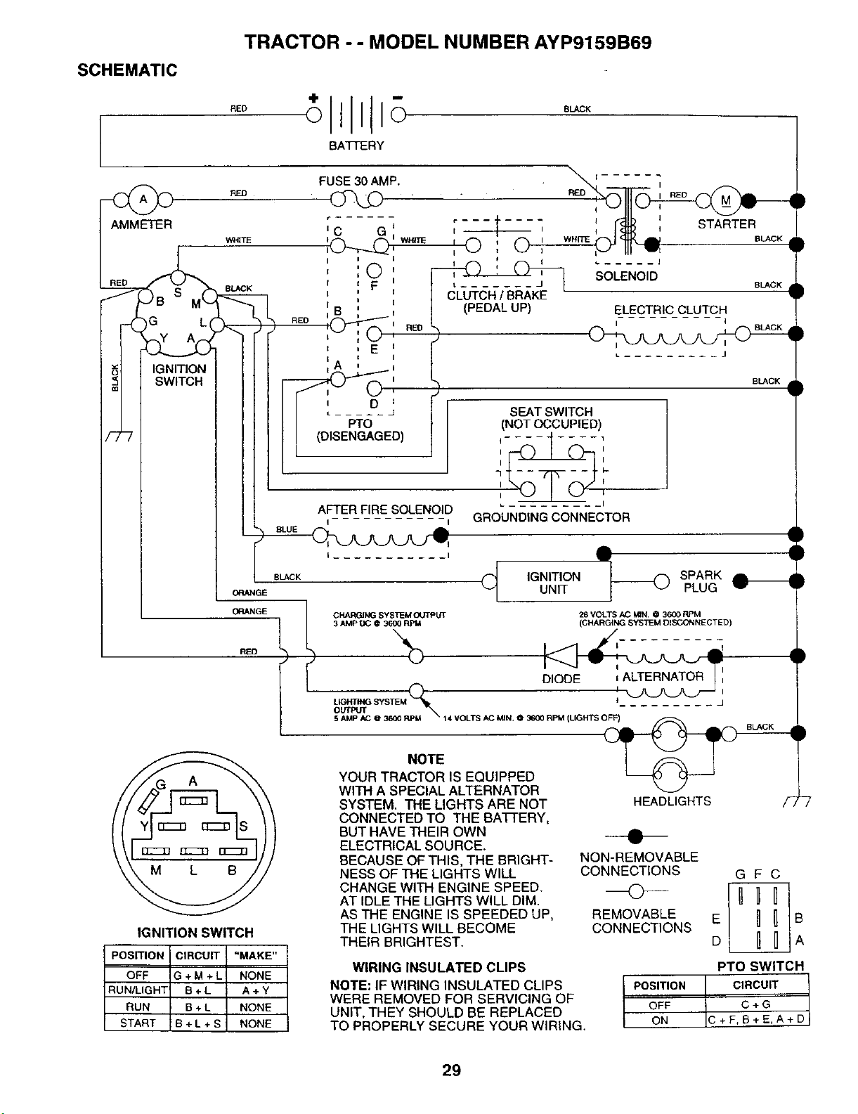
SCHEMATIC
RED
TRACTOR -- MODEL NUMBER AYP9159B69
BATTERY
BLACK
RED
WHITE
RED
FUSE30AMP.
r ......
IC G*
, ©
i F
I
I B
o
I -- I
'0 ' O_ w._
I =
CLUTCH/ BRAKE
(PEDALUP)
:A , i
II ' O _
II
I (DISENGAGED)
AFTERFIRESOLENOID
I I
BLACK
I ORANGE
ORANGE 1
ROD t
I rr-_ rr_n n---"n
SOLENOID
ELECTRIC CLUTCH
I I
I
IGNITION SWITCH
)
POSITION CIRCUIT "MAKE"
OFF G + M + L NONE
RUN/LIGH'[ B + L A + Y
RUN B + L NONE
START 8 + L + S NONE
SEATSWITCH
(NOTOCCUPIED)
{ ----1
I
7
I
I
.... I
GROUNDING CONNECTOR
CHARGING SYSTEM OUTPUT
3 AMP t_C @3600 RPM
BLACK
BLACK •
i
IGNITION [------0 SPARKUNIT PLUG
28 VOLTS AC M_N. @ 3600 RPM
(CHARGING SYSTEM DISCONNECTED)
DIODE
LIGHTING SYSTEM f •
OUTPUT
5 AMP AC @ 3600 RPI_ 14 VOLTS AC MJN. @ 3600 RPM (LIGHTS O_
NOTE
YOUR TRACTOR IS EQUIPPED
WITH A SPECIAL ALTERNATOR
SYSTEM. THE LIGHTS ARE NOT
CONNECTED TO THE BA'FFERY,
BUT HAVE THEIR OWN
ELECTRICAL SOURCE.
BECAUSE OF THIS, THE BRIGHT-
NESS OF THE LIGHTS WILL
CHANGE WITH ENGINE SPEED.
AT IDLE THE LIGHTS WILL DIM.
AS THE ENGINE IS SPEEDED UP,
THE LIGHTS WILL BECOME
THEIR BRIGHTEST.
WIRING INSULATED CLIPS
HEADLIGHTS
NOTE: IF WIRING INSULATED CLIPS
WERE REMOVED FOR SERVICING OF
UNIT, THEY SHOULD BE REPLACED
TO PROPERLY SECURE YOUR WIRING.
NON-REMOVABLE
CONNECTIONS G F C
REMOVABLE E
CONNECTIONS
D
PTO SWITCH
I POSITION CIRCUIT IOFF c+FC+G
ON +E,A+D
29
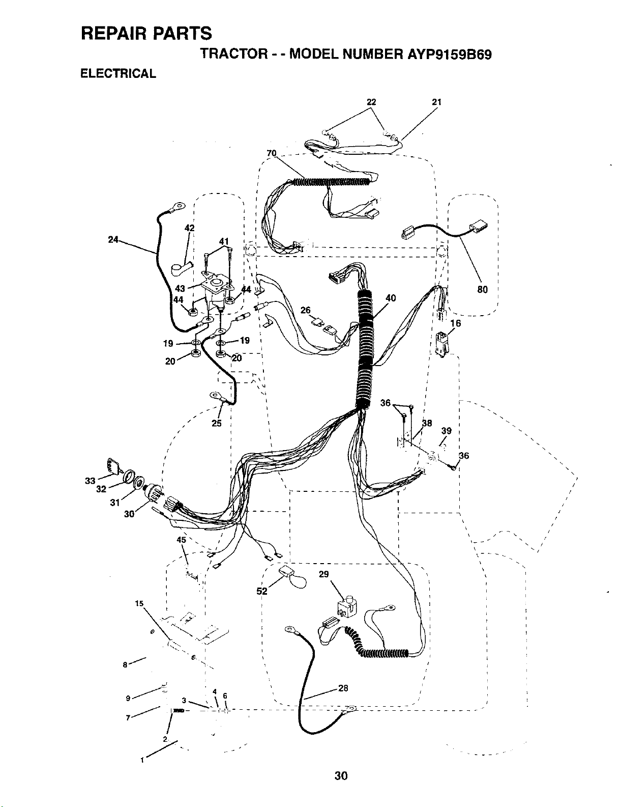
REPAIR PARTS
TRACTOR - - MODEL NUMBER AYP9159B69
ELECTRICAL
22 21
24_
41
19
4O
I
I
t
3O
/
/
/
/I
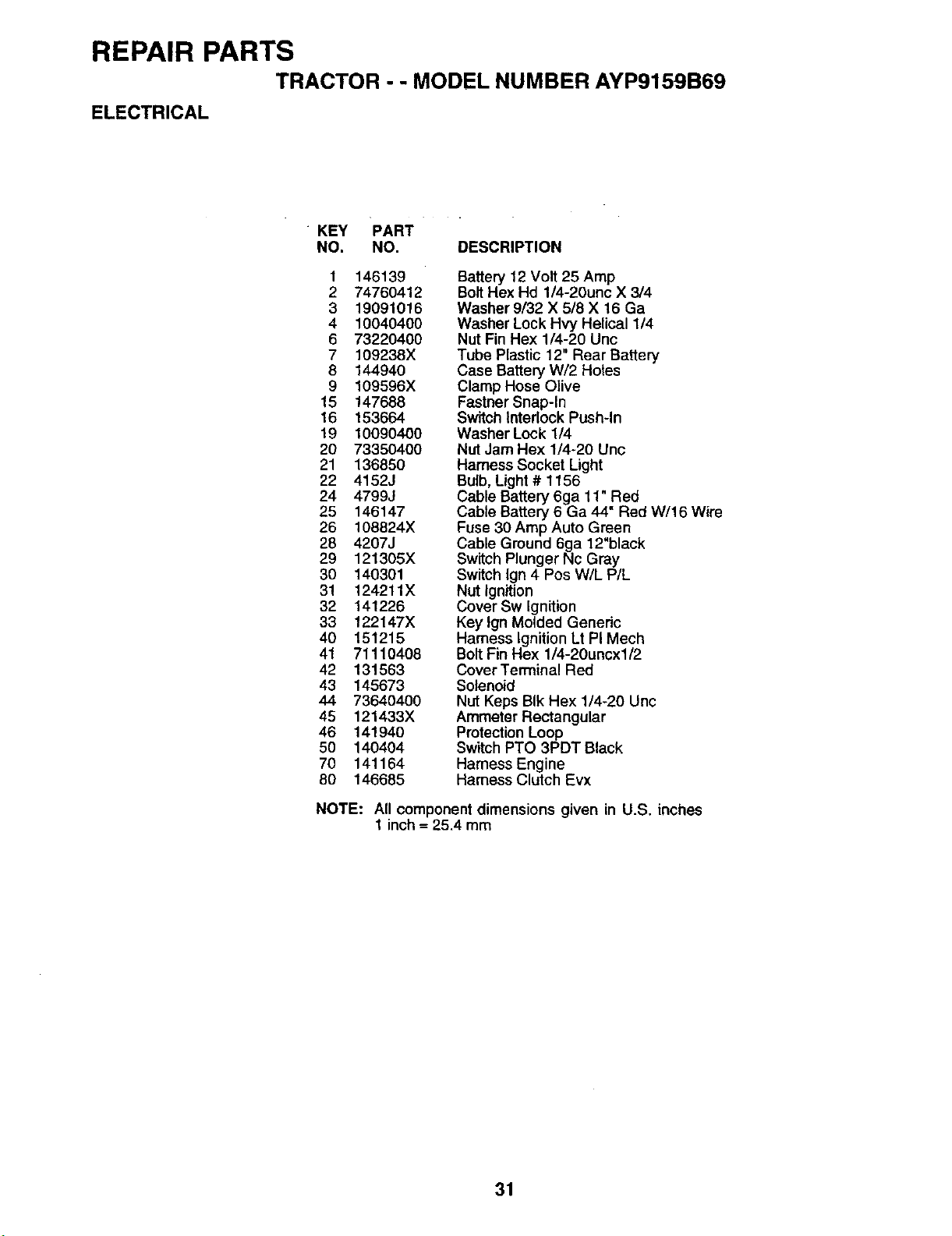
REPAIR PARTS
TRACTOR - - MODEL NUMBER AYP9159B69
ELECTRICAL
KEY PART
NO. NO. DESCRIPTION
1 146139
2 74760412
3 19091016
4 10040400
6 73220400
7 109238X
8 144940
9 109596X
15 147688
16 153664
19 10090400
20 73350400
21 136850
22 4152J
24 4799J
25 146147
26 108824X
28 4207J
29 121305X
30 140301
3! 124211X
32 141226
33 122147X
40 151215
41 71110408
42 131563
43 145673
44 73640400
45 121433X
46 141940
50 140404
70 141164
80 146685
Battery 12 Volt 25 Amp
Bolt Hex Hd 1/4-20unc X 3/4
Washer 9/32 X 5/8 X 16 Ga
Washer Lock Hvy Helical 1/4
Nut Fin Hex 1/4-20 Unc
Tube Plastic 12" Rear Battery
Case Battery W/2 Holes
Clamp Hose Olive
Fastner Snap-In
Switch Interlock Push-In
Washer Lock 1/4
Nut Jam Hex 1/4-20 Unc
Harness Socket Light
Bulb, Light # 1156
Cable Battery 6ga 11"Red
Cable Battery 6 Ga 44 Red W/16 Wire
Fuse 30 Amp Auto Green
Cable Ground 6ga 12"black
Switch Plunger Nc Gray
Switch Ign 4 Pos W/L P/L
Nut Ignition
Cover Sw Ignition
Key Ign Molded Generic
Harness Ignition Lt PI Mech
Bolt Fin Hex 1/4-20uncx1/2
Cover Terminal Red
Solenoid
Nut Keps BIk Hex 1/4-20 Unc
Ammeter Rectangular
Protection Loop
Switch PTO 3PDT Black
Harness Engine
Harness Clutch Evx
NOTE: All component dimensions given in U.S. inches
1 inch = 25.4 mm
31
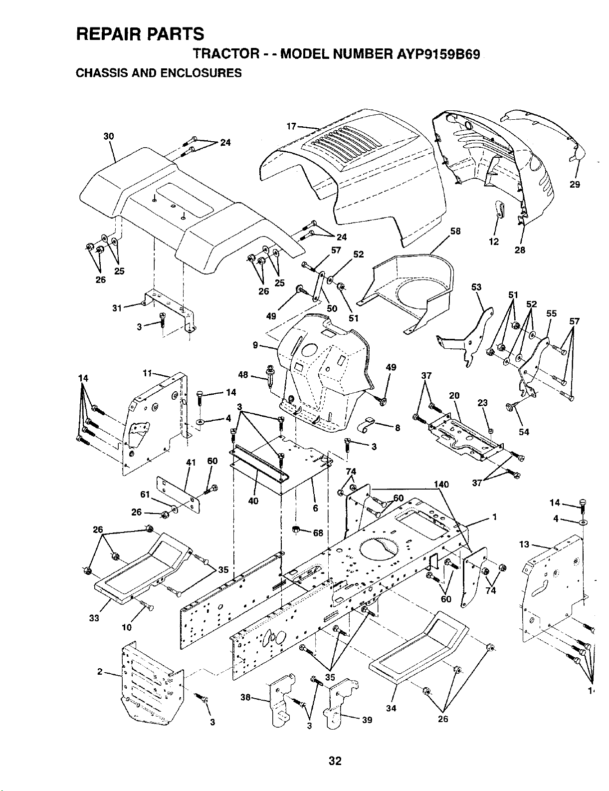
REPAIR PARTS
TRACTOR - - MODEL NUMBER AYP9159B69
CHASSIS AND ENCLOSURES
3O
31
26
49
49
14 37
12
28
53
54
29
57
26
33
10
4O
i i
26
1 I
32
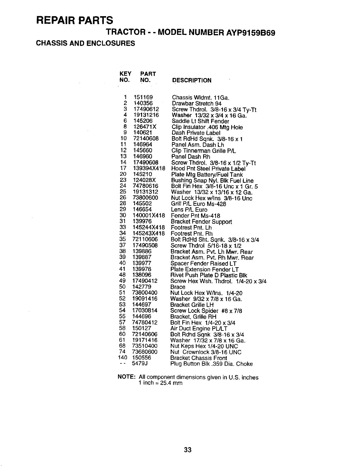
REPAIR PARTS
TRACTOR - - MODEL NUMBER AYP9159B69
CHASSIS AND ENCLOSURES
KEY PART
NO. NO. DESCRIPTION
1 151169
2 140356
3 17490612
4 19131216
6 145206
8 126471X
9 140621
10 721406O8
11 146964
12 145660
13 146960
14 17490608
17 139394X418
20 145210
23 124028X
24 74780616
25 19131312
26 73800600
28 145502
29 146654
30 140001X418
31 139976
33 145244X418
34 145243X418
35 72110606
37 17490508
38 139886
39 139887
40 139977
41 139978
48 138O96
49 17490412
50 142779
51 73800400
52 19091416
53 144697
54 17030814
55 144696
57 74780412
58 150127
60 72140606
61 19171416
68 73510400
74 73680600
140 150556
-- 5479J
Chassis Wldmt. 11Ga.
Drawbar Stretch 94
Screw Thdrol. 3/8-16 x 3/4 Ty-Tt
Washer 13/32 x 3/4 x 16 Ga.
Saddle Lt Shift Fender
Clip Insulator .406 Mtg Hole
Dash Pdvate Label
Bolt RdHd Sqnk. 3/8-16 x 1
Panel Asm. Dash Lh
Clip Tinnerman Grille P/L
Panel Dash Rh
Screw Thdrol. 3/8-16 x 1/2 Ty-Tt
Hood Pnt Steel Private Label
Plate Mtg Battery/Fuel Tank
Bushing Snap Nyl. BIk Fuel Line
Bolt Fin Hex 3/8-16 Unc x 1 Gr. 5
Washer 13/32 x 13/16 x 12 Ga.
Nut Lock Hex w/Ins 3/8-16 Unc
Grill P/L Euro Ms-428
Lens P/L Euro
Fender Pnt Ms-418
Bracket Fender Support
Footrest Pnt. Lh
Footrest Pnt. Rh
Bolt RdHd Sht. Sqnk. 3/8-16 x 3/4
Screw Thdrol 5/16-18 x 1/2
Bracket Asm. Pvt. Lh Mwr. Rear
Bracket Asm. Pvt. Rh Mwr. Rear
Spacer Fender Raised LT
Plate Extension Fender LT
Rivet Push Plate D Plastic BIk
Screw Hex Wsh. Thdrol. 1/4-20 x 3/4
Brace
Nut Lock Hex W/Ins. 1/4-20
Washer 9/32 x 7/8 x 16 Ga.
Bracket Gdlle LH
Screw Lock Spider #8 x 7/8
Bracket, Grille RH
Bolt Fin Hex 1/4-20 x 3/4
Air Duct Engine PL/LT
Bolt Rdhd Sqnk 3/8-16 x 3/4
Washer 17/32 x 7/8 x 16 Ga.
Nut Keps Hex 1/4-20 UNC
Nut Crownlock 3/8-16 UNC
Bracket Chassis Front
Plug Button BIk .359 Dia. Choke
NOTE: All component dimensions given in U.S. inches
1 inch = 25.4 mm
33
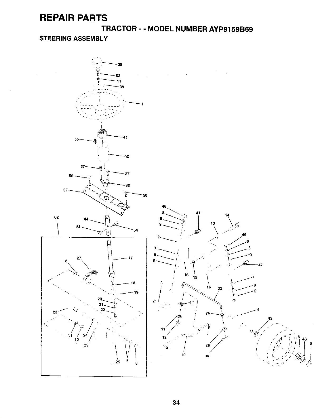
REPAIR PARTS
TRACTOR - . MODEL NUMBER AYP9159B69
STEERING ASSEMBLY
62
~ i
27
8
117
46
14
: 46
43
/ /
! /
\ I _ / I/
43
34
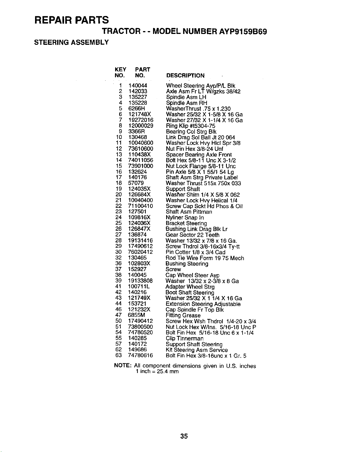
REPAIR PARTS
TRACTOR - - MODEL NUMBER AYP9159B69
STEERING ASSEMBLY
KEY PART
NO. NO.
" 1 140044
2 142033
3 135227
4 135228
5 6266H
6 121748X
7 19272016
8 12000029
9 3366R
10 130468
11 10040600
12 73610600
13 110438X
14 74011056
15 73901000
16 132624
17 140176
18 57079
19 124035X
20 126684X
21 10040400
22 71100410
23 127501
24 109816X
25 124036X
26 126847X
27 136874
28 19131416
29 17490612
30 76020412
32 130465
36 102803X
37 152927
38 140045
39 19133808
41 100711L
42 140216
43 121749X
44 153721
46 121232X
47 6855M
50 17490412
51 738OO500
54 74780520
55 140285
57 140172
62 149686
63 74780616
DESCRIPTION
Wheel Steering Ayp/P/L BIk
Axle Asm Fr LT W/gzks 38/42
Spindle Asm LH
Spindle Asm RH
WasherThrust .75 x 1.230
Washer 25/32 X 1-5/8 X 16 Ga
Washer 27/32 X 1-1/4 X t6 Ga
Ring Klip #t5304-75
Bearing Col Strg BIk
Link Drag Sol BallJt 20 064
Washer Lock Hvy Hlcl Spr 3/8
Nut Fin Hex 3/8-24 Unf
Spacer Bearing Axle Front
Bolt Hex 5/8-11 Unc X 3-1/2
Nut Lock Flange 5/8-11 Unc
Pin Axle 5/8 X 1 55/1 54 Lg
Shaft Asm Strg Private Label
Washer Thrust 515x 750x 033
Support Shaft
Washer Shim 1/4 X 5/8 X 062
Washer Lock Hvy Helical 1/4
Screw Cap Sckt Hd Phos & Oil
Shaft Asm Pittman
Nyliner Snap In
Bracket Steedng
Bushing Link Drag BIk Lr
Gear Sector 22 Teeth
Washer 13/32 x 7/8 x 16 Ga.
Screw Thdrol 3/8-16x3/4 Ty-tt
Pin Cotter 1/8 x 3/4 Cad
Rod Tie Wire Form 19 75 Mech
Bushing Steering
Screw
Cap Wheel Steer Ayp
Washer 13/32 x 2-3/8 x 8 Ga
Adapter Wheel Strg
Beet Shaft Steering
Washer 25/32 X 1 1/4 X 16 Ga
Extension Steering Adjustable
Cap Spindle Fr Top BIk
Fitting Grease
Screw Hex Wsh Thdrol 1/4-20 x 3/4
Nut Lock Hex W/Ins. 5/16-18 Unc P
Bolt Fin Hex 5/16-18 Unc 6 x 1-1/4
Clip Tinnerman
Support Shaft Steering
Kit Steering Asm Service
Bolt Fin Hex 3/8-16unc x 1 Gr. 5
NOTE: All component dimensions given in U.S. inches
1 inch = 25.4 mm
35
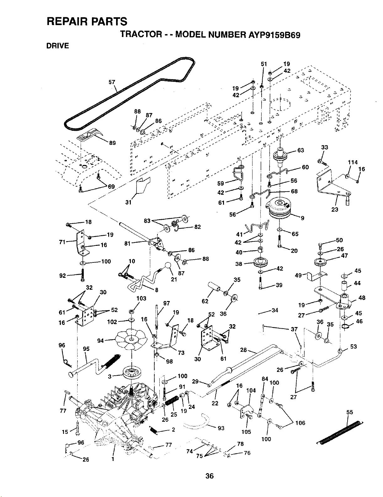
REPAIR PARTS
TRACTOR - - MODEL NUMBER AYP9159B69
DRIVE
10
103
87
21 35
97 62_
/ 19 52 36
98
16
84100
104
27
45
• 53
26
22
24
100
55
36
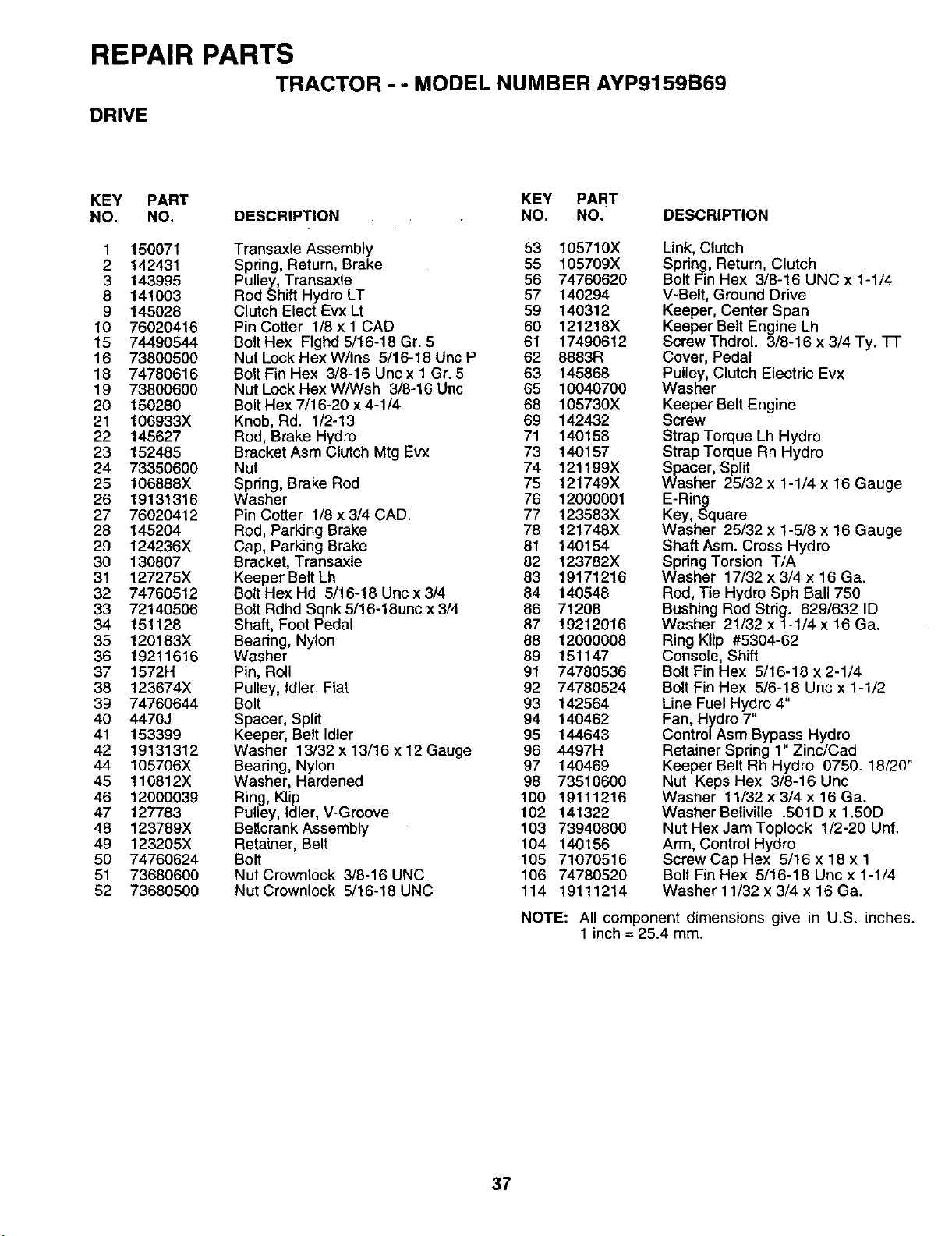
REPAIR PARTS
TRACTOR - - MODEL NUMBER AYP9159B69
DRIVE
KEY PART KEY PART
NO. NO. DESCRIPTION NO. NO. DESCRIPTION
1 150071 Transaxle Assembly 53 105710X
2 142431 Spring, Return, Brake 55 105709X
3 143995 Pulley, Transaxle 56 74760620
8 141003 Rod Shift Hydro LT 57 140294
9 145028 Clutch Elect Evx Lt 59 140312
10 76020416 Pin Cotter 1/8 x 1 CAD 60 121218X
15 74490544 Bolt Hex FIghd 5/16-18 Gr. 5 61 17490612
16 73800500 Nut Lock Hex W/Ins 5/16-18 Unc P 62 8883R
18 74780616 BoltFin Hex 3/8-16 Unc x 1 Gr. 5 63 145868
19 73800600 Nut Lock Hex W/Wsh 3/8-16 Unc 65 10040700
20 150280 Bolt Hex 7/16-20 x 4-1/4 68 105730X
21 106933X Knob, Rd. 1/2-13 69 142432
22 145627 Rod, Brake Hydro 71 140158
23 152485 Bracket Asm Clutch Mtg Ev'x 73 140157
24 73350600 Nut 74 121199X
25 106888X Spring, Brake Rod 75 121749X
26 19131316 Washer 76 12000001
27 76020412 Pin Cotter 1/8 x 3/4 CAD. 77 123583X
28 145204 Rod, Parking Brake 78 121748X
29 124236X Cap, Parking Brake 81 140154
30 130807 Bracket, Transaxle 82 123782X
31 127275X KeeperBeltLh 83 19171216
32 74760512 Bolt Hex Hd 5/16-18 Unc x 3/4 84 140548
33 72140506 Bolt Rdhd Sqnk5/16-18unc x3/4 86 71208
34 151128 Shaft, Foot Pedal 87 19212016
35 120183X Beadng, Nylon 88 12000008
36 19211616 Washer 89 151147
37 1572H Pin, Roll 91 74780536
38 123674X Pulley, Idler, Fiat 92 74780524
39 74760644 Bolt 93 142564
40 4470J Spacer, Split 94 140462
41 153399 Keeper, Belt Idler 95 144643
42 19131312 Washer 13/32 x 13/16 x 12 Gauge 96 4497H
44 105706X Bearing, Nylon 97 140469
45 110812X Washer, Hardened 98 73510600
46 12000039 Ring, Klip 100 19111216
47 127783 Pulley, Idler, V-Groove 102 141322
48 123789X Bellcrank Assembly 103 73940800
49 123205X Retainer, Belt 104 140156
50 74760624 Bolt 105 71070516
51 73680600 Nut Crownlock 3/8-16 UNC 106 74780520
52 73680500 NutCrownlock 5/16-18UNC 114 19111214
Link, Clutch
Spring, Return, Clutch
Bolt Fin Hex 3/8-16 UNC x 1-1/4
V-Belt, Ground Drive
Keeper, Center Span
Keeper Belt Engine Lh
Screw Thdrol. 3/8-16 x 3/4 Ty. "IT
Cover, Pedal
Pulley, Clutch Electric Evx
Washer
Keeper Belt Engine
Screw
Strap Torque Lh Hydro
Strap Torque Rh Hydro
Spacer, Split
Washer 25/32 x 1-1/4 x 16 Gauge
E-Ring
Key, Square
Washer 25/32 x 1-5/8 x 16 Gauge
Shaft Asm. Cross Hydro
Spring Torsion T/A
Washer 17/32 x 3/4 x 16 Ga.
Rod, Tie Hydro Sph Ball 750
Bushing Rod Strig. 629/632 ID
Washer 21/32 x 1-1/4 x 16 Ga.
Ring Klip #5304-62
Console, Shift
Bolt Fin Hex 5/16-18 x 2-1/4
Bolt Fin Hex 5/6-18 Unc x 1-1/2
Line Fuel Hydro 4"
Fan, Hydro 7"
Control Asm Bypass Hydro
Retainer Spring 1" Zinc/Cad
Keeper Belt Rh Hydro 0750. 18/20"
Nut Keps Hex 3/8-16 Unc
Washer 11/32 x 3/4 x 16 Ga.
Washer Beliville .501D x 1.50D
Nut Hex Jam Toplock 1/2-20 Unf.
Arm, Control Hydro
Screw Cap Hex 5/16 x 18 x 1
Bolt Fin Hex 5/16-18 Unc x 1-1/4
Washer 11/32 x 3/4 x 16 Ga.
NOTE: All component dimensions give in U.S. inches.
1 inch = 25.4 mm.
37
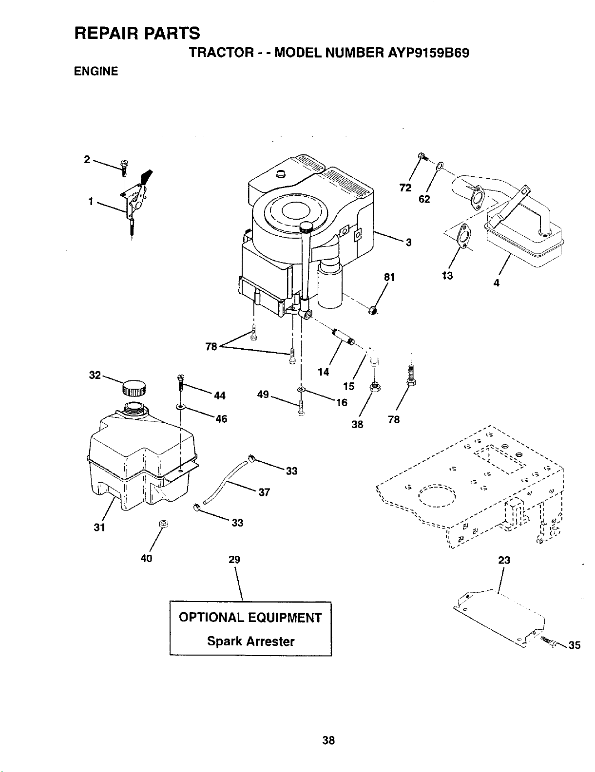
REPAIR PARTS
TRACTOR - - MODEL NUMBER AYP9159B69
ENGINE
81
i
78
78
38
29
OPTIONAL EQUIPMENT I
Spark Arrester
72
62
13
4
23
35
38
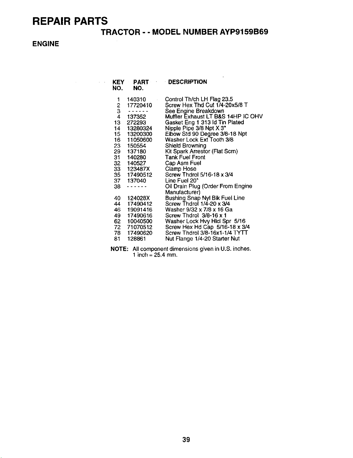
REPAIR PARTS
TRACTOR - - MODEL NUMBER AYP9159B69
ENGINE
KEY PART DESCRIPTION
NO. NO.
1 140310
2 17720410
3
4 137352
13 272293
14 13280324
15 13200300
16 11050600
23 150554
29 137180
31 140280
32 140527
33 123487X
35 17490512
37 137040
38 ......
40 124028X
44 17490412
46 19091416
49 17490616
62 10040500
72 71070512
78 17490620
81 128861
Control Th/ch LH Flag 23.5
Screw Hex Thd Cut 1/4-20x5/8 T
See Engine Breakdown
Muffler Exhaust LT B&S 14HP IC OHV
Gasket Eng 1 313 Id Tin Plated
Nipple Pipe 3/8 Npt X 3"
Elbow Std 90 Degree 3/8-18 Npt
Washer Lock Ext Tooth 3/8
Shield Browning
Kit Spark Arrestor (Flat Scm)
Tank Fuel Front
Cap Asm Fuel
Clamp Hose
Screw Thdrol 5/16-18 x 3/4
Line Fuel 20"
Oil Drain Plug (Order From Engine
Manufacturer)
Bushing Snap Nyl BIk Fuel Line
Screw Thdrol 1/4-20 x 3/4
Washer 9/32 x 7/8 x 16 Ga
Screw Thdrol 3/8-16 x 1
Washer Lock Hvy HIcl Spr 5/16
Screw Hex Hd Cap 5/16-18 x 3/4
Screw Thdrol 3/8-16x1-1/4 TY3-F
Nut Flange 1/4-20 Starter Nut
NOTE: All component dimensions given in U.S. inches,
1 inch = 25.4 mm.
39
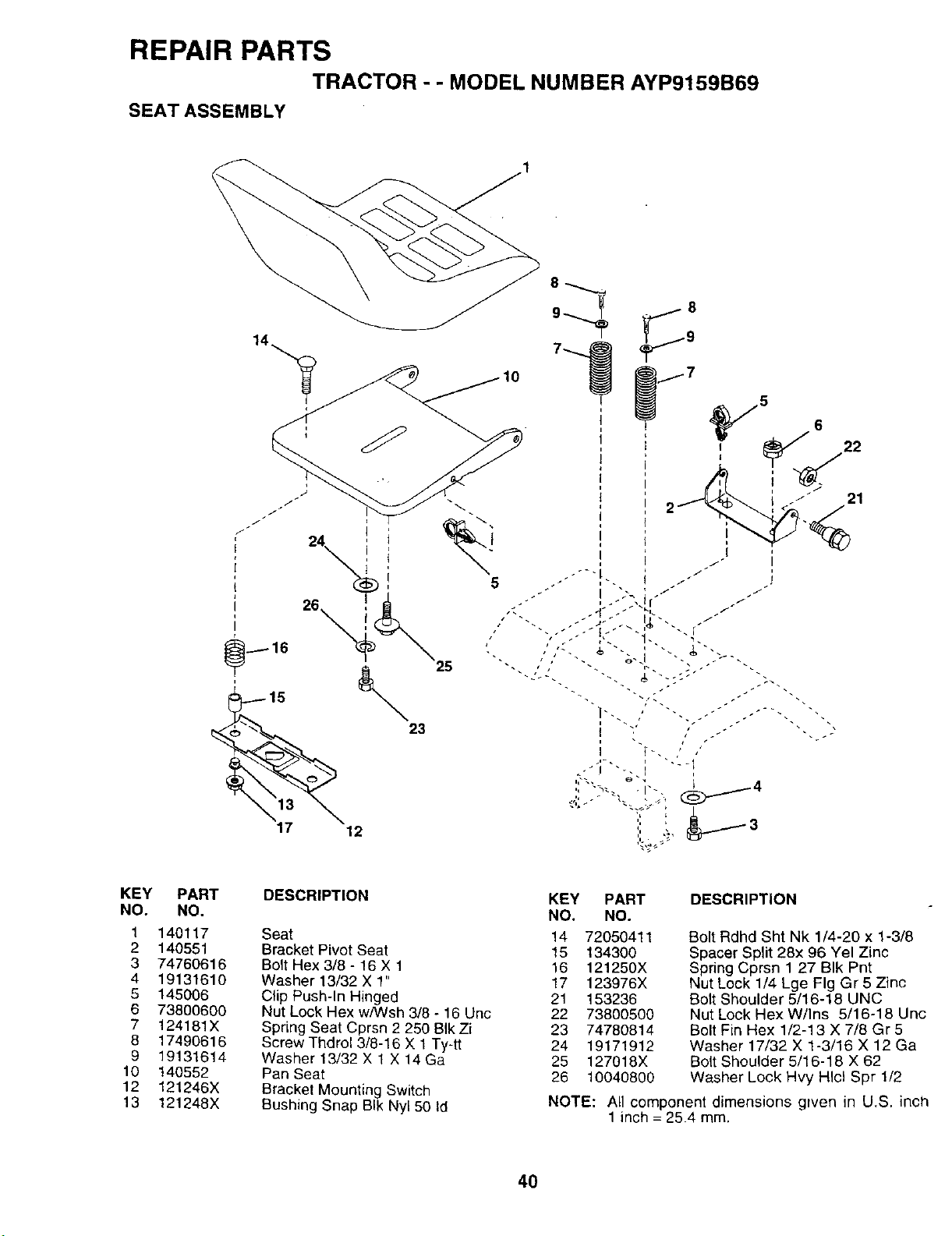
REPAIR PARTS
TRACTOR - - MODEL NUMBER AYP9159B69
SEAT ASSEMBLY
_15
17 12
5
23
KEY
NO.
1
2
3
4
5
6
7
6
9
10
12
13
PART
NO.
140117
140551
74760616
19131610
145006
73800600
124181X
17490616
19131614
140552
121246X
121248X
DESCRIPTION
Seat
Bracket Pivot Seat
Bolt Hex 3/8 - 16 X 1
Washer 13/32 X 1"
Clip Push-In Hinged
Nut Lock Hex w/Wsh 3/8 - 16 Unc
SprLng Seat Cprsn 2 250 BIk Zi
Screw Thdrol 3/8-16 X 1 Ty-tt
Washer 13/32 X 1 X 14 Ga
Pan Seat
Bracket Mounting Switch
Bushing Snap BIk Nyl 50 Id
KEY PART DESCRIPTION
NO, NO.
14 72050411
15 134300
16 121250X
17 123976X
21 153236
22 73800500
23 74780814
24 19171912
25 127018X
26 10040800
Bolt Rdhd Sht Nk 1/4-20 x 1-3/8
Spacer Split 28x 96 Yel Zinc
Spring Cprsn 127 BIk Pnt
Nut Lock 1/4 Lge Fig Gr 5 Zinc
Bolt Shoulder 5/16-18 UNC
Nut Lock Hex W/Ins 5/16-18 Unc
Bolt Fin Hex 1/2-13 X 7/8 Gr 5
Washer 17/32 X 1-3/16 X 12 Ga
Bolt Shoulder 5/16-18 X 62
Washer Lock Hvy HIcl Spr 1/2
NOTE: All component dimensions grven in U.S. inch
1 inch = 25.4 mm.
40
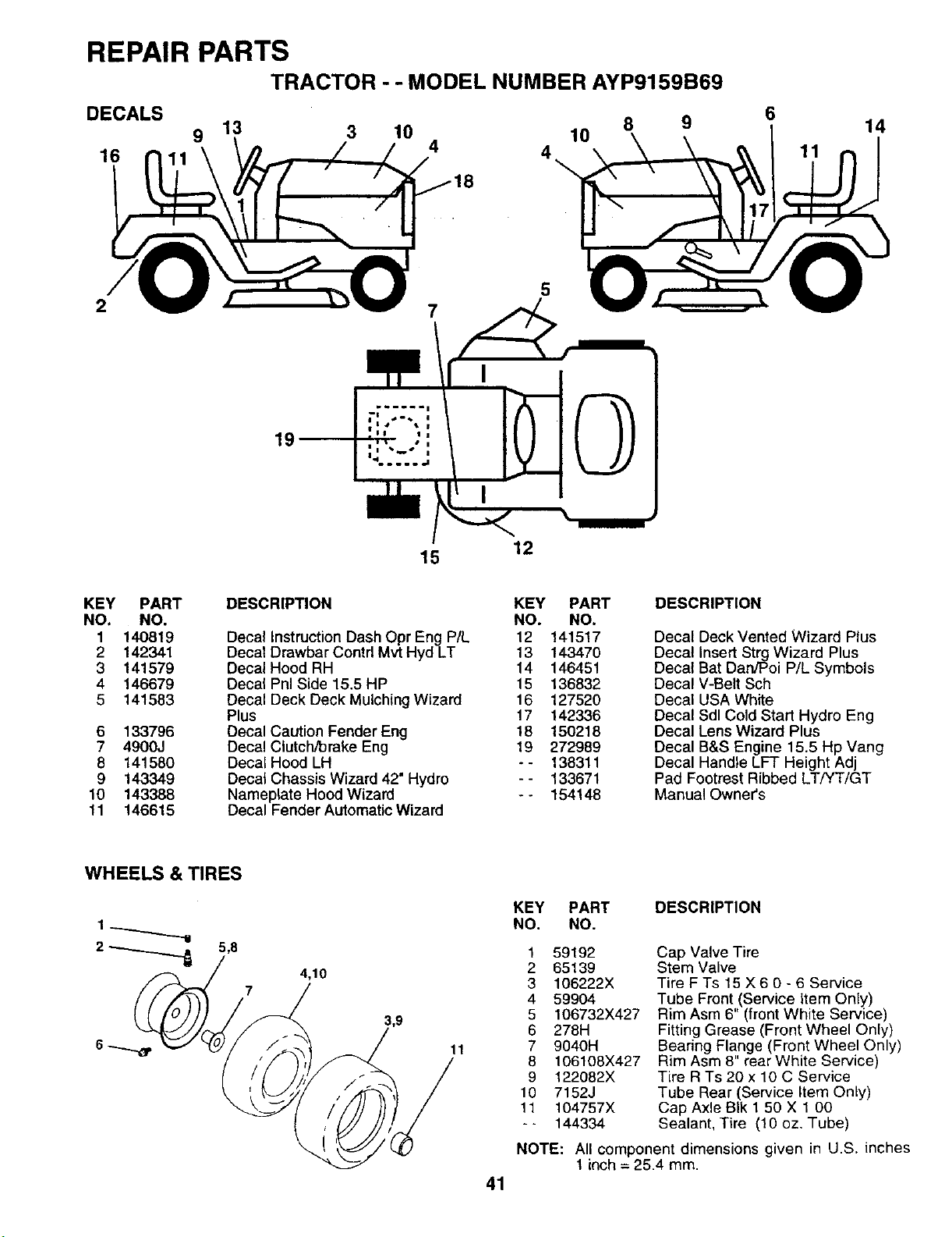
REPAIR PARTS
TRACTOR - - MODEL NUMBER AYP9159B69
DECALS 8
9 13 3 10 10
16 4 4
9
6
11
14
2
5
15 12
KEY PART
NO. NO.
1 140819
2 142341
3 141579
4 146679
5 141583
6 133796
7 4900J
8 141580
9 143349
10 143388
11 146615
DESCRIPTION
Decal Instruction Dash Opr Eng P/t.
Decal Drawbar Contrl Mvt Hyd LT
Decal Hood RH
Decal Pnl Side 15.5 HP
Decal Deck Deck Mulching Wizard
Plus
Decal Caution Fender Eng
Decal Clutch/brake Eng
Decal Hood LH
Decal Chassis Wizard 42= Hydro
Nameplate Hood Wizard
Decal Fender Automatic Wizard
KEY PART
NO. NO.
12 141517
13 143470
14 146451
15 136832
16 127520
17 142336
18 15O218
19 272989
-- 138311
-- 133671
-- 154148
DESCRIPTION
Decal Deck Vented Wizard Plus
Decal Insert Strg Wizard Plus
Decal Bat Dan/Poi P/L Symbols
Decal V-Belt Sch
Decal USA White
Decal Sdl Cold Start Hydro Eng
Decal Lens Wizard Plus
Decal B&S Engine 15.5 Hp Vang
Decal Handle LFT Height Adj
Pad Footrest Ribbed LT/YT/GT
Manual Owner's
WHEELS & TIRES
2 _ 5,8
4,10
7
KEY PART DESCRIPTION
NO. NO.
1 59192
2 65139
3 106222X
4 59904
5 106732X427
6 278H
11 7 9040H
8 106108X427
9 122082X
10 7152J
11 104757X
-- 144334
41
Cap Valve Tire
Stem Valve
Tire F Ts 15 X 6 0 - 6 Service
Tube Front (Service Item Only)
Rim Asm 6" (front White Service)
Fitting Grease (Front Wheel Only)
Bearing Flange (Front Wheel Only)
Rim Asm 8" rear White Service)
Tire R Ts 20 x 10 C Service
Tube Rear (Service Item OnLy)
Cap Axle BIk 1 50 X 1 00
Sealant, Tire (10 oz. Tube)
NOTE: All component dimensions given in U.S. inches
1 inch= 25.4 ram.
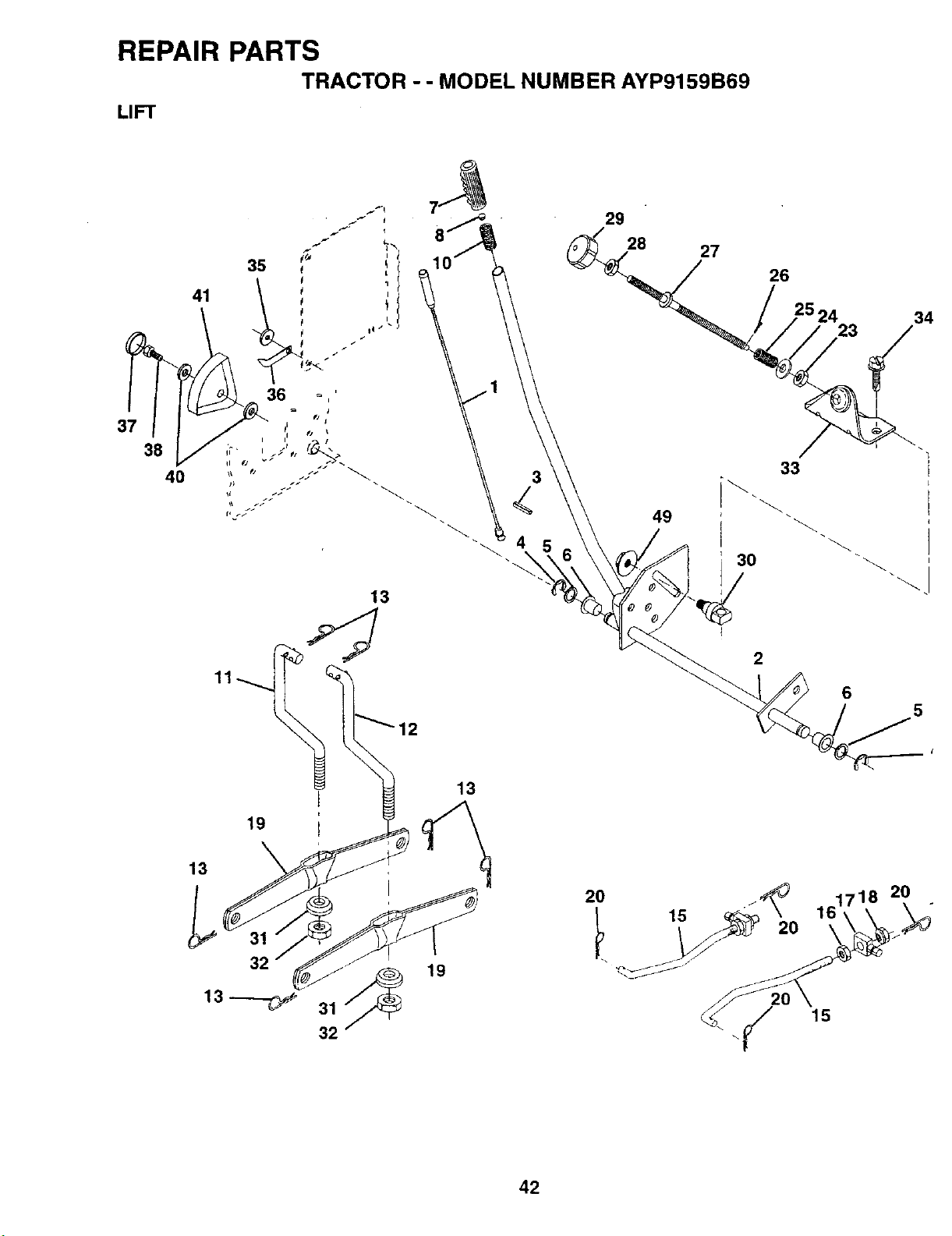
REPAIR PARTS
TRACTOR - - MODEL NUMBER AYP9159B69
LIFT
37
41
38
4O
13
29
28
27
49
26
33
I
3O
2
23
6
5
34
19
13
13
32
13_
32 /
19
161718 20
15
42
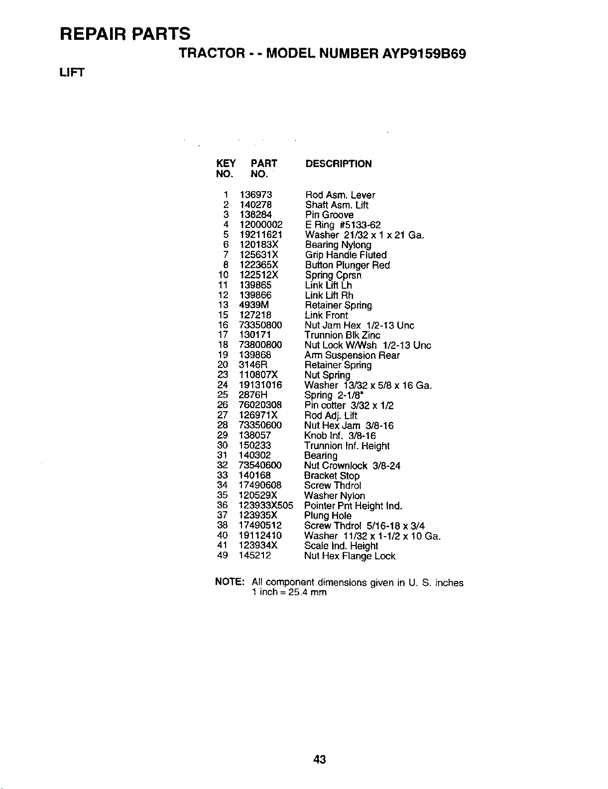
REPAIR PARTS
TRACTOR - - MODEL NUMBER AYP9159B69
LIFT
KEY PART DESCRIPTION
NO. NO.
1 136973 Rod Asm. Lever
2 140278 Shaft Asm. Lift
3 138284 Pin Groove
4 12000002 E Ring #5133-62
5 19211621 Washer 21/32 x 1 x 21 Ga.
6 120183X Bearing Nylong
7 125631X Grip Handle Fluted
8 122365X Button Plunger Red
10 122512X Spring Cprsn
11 139865 Link Lift Lh
12 139866 Link Lift Rh
13 4939M Retainer Spring
15 127218 Link Front
16 73350800 Nut Jam Hex 1/2-13 Unc
17 130171 Trunnion BIkZinc
18 73800800 Nut Lock W/Wsh 1/2-13 Unc
19 139868 Arm Suspension Rear
20 3146R Retainer Spring
23 110807X Nut Spring
24 19131016 Washer 13/32x5/8x16Ga.
25 2876H Spring 2-1/8"
26 76020308 Pin cotter 3/32 x 1/2
27 126971X Rod Adj. Lift
28 73350600 Nut Hex Jam 318-16
29 138057 Knob Inf. 3/8-16
30 150233 Trunnion Inf. Height
31 140302 Bearing
32 73540600 Nut Crownlock 3/6-24
33 140168 Bracket Stop
34 17490608 Screw Thdrol
35 120529X Washer Nylon
36 123933X505 Pointer Pnt Height Ind.
37 123935X Plung Hole
38 17490512 ScrewThdrol 5/16-18 x 3/4
40 19112410 Washer 11/32x1-1/2x10Ga.
41 123934X Scale Ind, Height
49 145212 Nut Hex Flange Lock
NOTE: At1component dimensions given in U. S. inches
1 inch = 25.4 mm
43
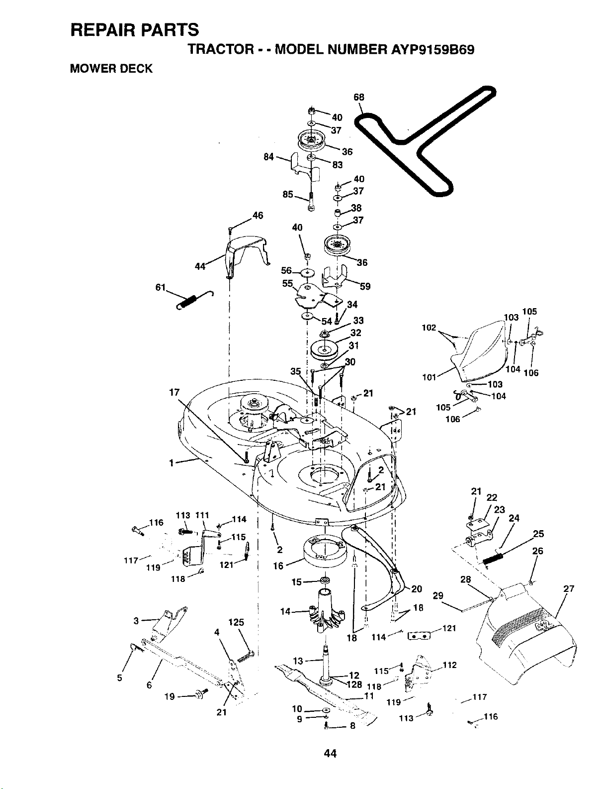
REPAIR PARTS
TRACTOR - - MODEL NUMBER AYP9159B69
MOWER DECK
34
17
105
106
113 111 114
118_J_
3_._ 125
25
26
27
44
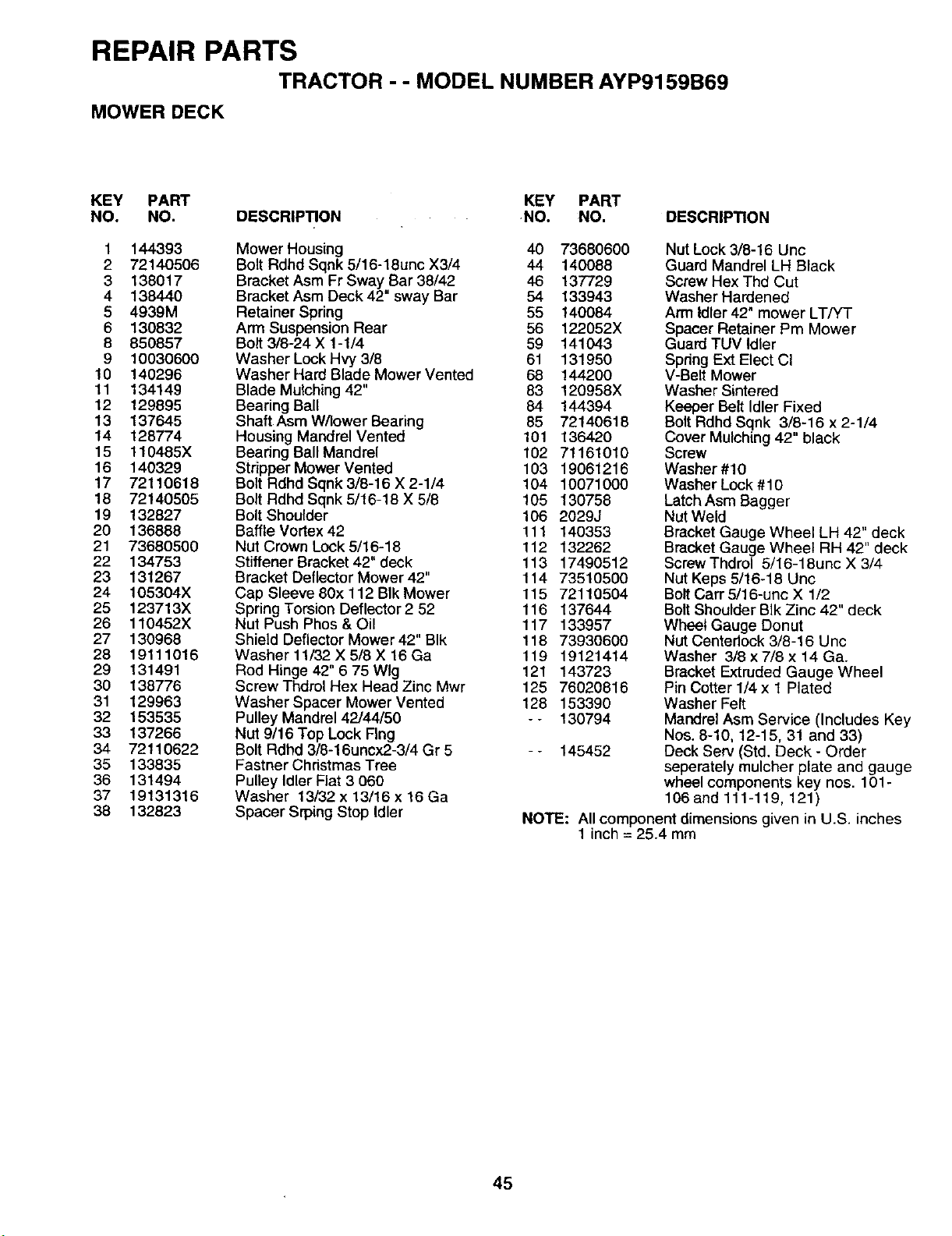
REPAIR PARTS
TRACTOR - - MODEL NUMBER AYP9159B69
MOWER DECK
KEY PART KEY PART
NO. NO. DESCRIPTION -NO. NO. DESCRIPTION
1 144393
2 72140506
3 138017
4 138440
5 4939M
6 130832
8 850857
9 10030600
10 140296
11 134149
12 129895
13 137645
14 128774
15 110485X
16 140329
17 72110618
18 72140505
19 132827
20 136888
21 73680500
22 134753
23 131267
24 105304X
25 123713X
26 110452X
27 130968
28 19111016
29 131491
30 138776
31 129963
32 153535
33 137266
34 72110622
35 133835
36 131494
37 19131316
38 132823
Mower Housing 40 73680600
Bolt Rdhd Sqnk 5/16-18unc X3/4 44 140088
Bracket Asm Fr Sway Bar 38/42 46 137729
Bracket Asm Deck 42" sway Bar 54 133943
Retainer Spdng 55 140084
Arm Suspension Rear 56 122052X
Bolt 3/8-24 X 1-1/4 59 141043
Washer Lock Hvy 3/8 61 131950
Washer Hard Blade Mower Vented 68 144200
Blade Mulching 42" 83 120958X
Bearing Ball 84 144394
Shaft Asm W/lower Bearing 85 72140618
Housing Mandrel Vented 101 136420
Bearing Ball Mandrel 102 71161010
Stripper Mower Vented 103 19061216
Bolt Rdhd Sqnk 3/8-16 X 2-1/4 104 10071000
Bolt Rdhd Sqnk 5/16-18 X 5/8 105 130758
Bolt Shoulder 106 2029J
Baffle Vortex 42 111 140353
Nut Crown Lock 5/16-18 112 132262
Stiffener Bracket 42" deck 113 17490512
Bracket Deflector Mower 42" 114 73510500
Cap Sleeve 80x 112 BIk Mower 115 72110504
Spring Torsion Deflector 2 52 116 137644
Nut Push Phos & Oil 117 133957
Shield Deflector Mower 42" BIk 118 73930600
Washer 11/32 X 5/8 X 16 Ga 119 19121414
Rod Hinge 42" 6 75 Wig 121 143723
Screw Thdrol Hex Head Zinc Mwr 125 76020816
Washer Spacer Mower Vented 128 153390
Pulley Mandrel 42/44/50 - - 130794
Nut 9/16 Top Lock FIng
Bolt Rdhd 3/8-16uncx2-3/4 Gr 5 - - 145452
Fastner Christmas Tree
Pulley Idler Flat 3 060
Washer 13/32 x 13/16 x !6 Ga
Spacer Srping Stop Idler
Nut Lock 3/8-16 Unc
Guard Mandrel LH Black
Screw Hex Thd Cut
Washer Hardened
Arm Idler 42" mower LT/YT
Spacer Retainer Pm Mower
Guard TUV Idler
Spdng Ext Elect CI
V-Belt Mower
Washer Sintered
Keeper Belt Idler Fixed
Bolt Rdhd Sqnk 3/8-16 x 2-1/4
Cover Mulching 42" black
Screw
Washer #10
Washer Lock #10
Latch Asm Bagger
Nut Weld
Bracket Gauge Wheel LH 42" deck
Bracket Gauge Wheel RH 42" deck
Screw Thdrol 5/16-18unc X 3/4
Nut Keps 5/16-18 Unc
Bolt Carr 5/16-unc X 1/2
Bolt Shoulder BIk Zinc 42" deck
Wheel Gauge Donut
Nut Centedock 3/8-16 Unc
Washer 3/8 x 7/8 x 14 Ga.
Bracket Extruded Gauge Wheel
Pin Cotter 1/4 x t Plated
Washer Felt
Mandrel Asm Service (Includes Key
Nos. 8-10, 12-15, 31 and 33)
Deck Serv (Std. Deck - Order
seperately mulcher plate and gauge
wheel components key nos. 101-
106 and 111-119, 121)
NOTE: All component dimensions given in U.S. inches
1 inch= 25.4 mm
45
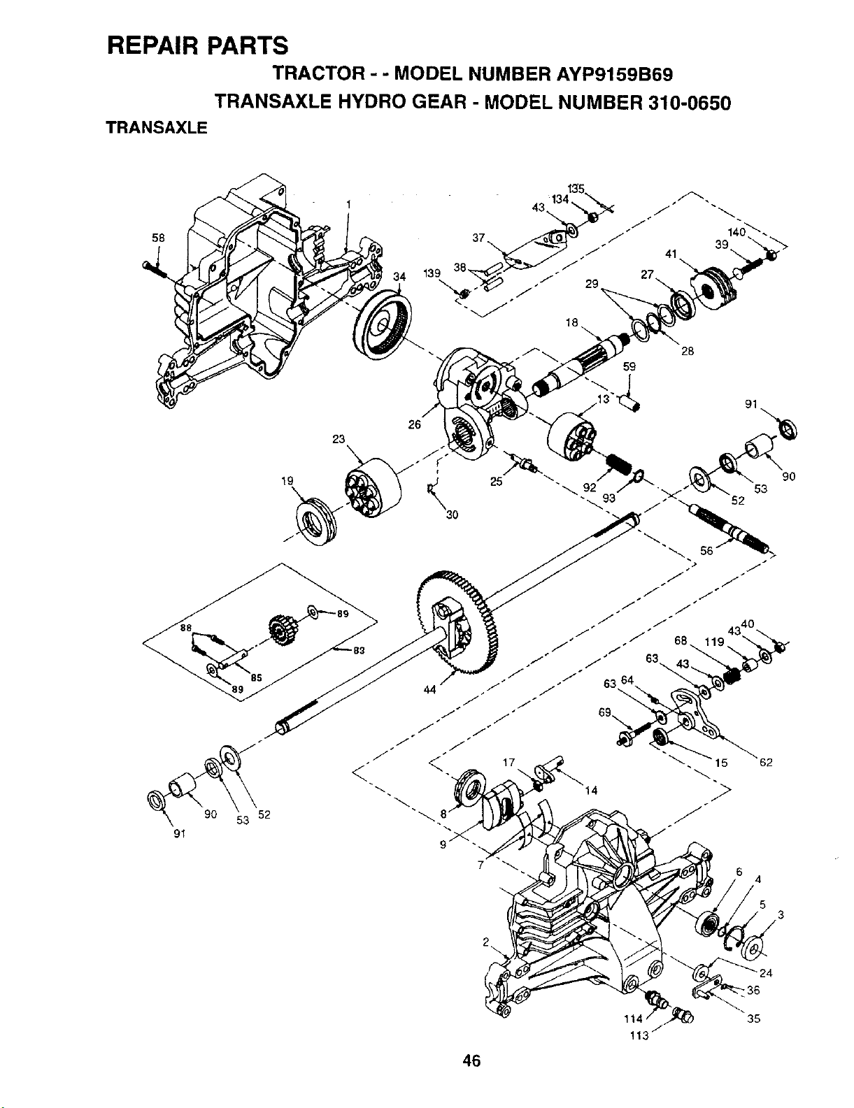
REPAIR PARTS
TRACTOR - - MODEL NUMBER AYP9159B69
TRANSAXLE HYDRO GEAR - MODEL NUMBER 310-0650
TRANSAXLE
58
23
34
26
19
• 83
#
91
53
52
2
4
5
9O
35
46
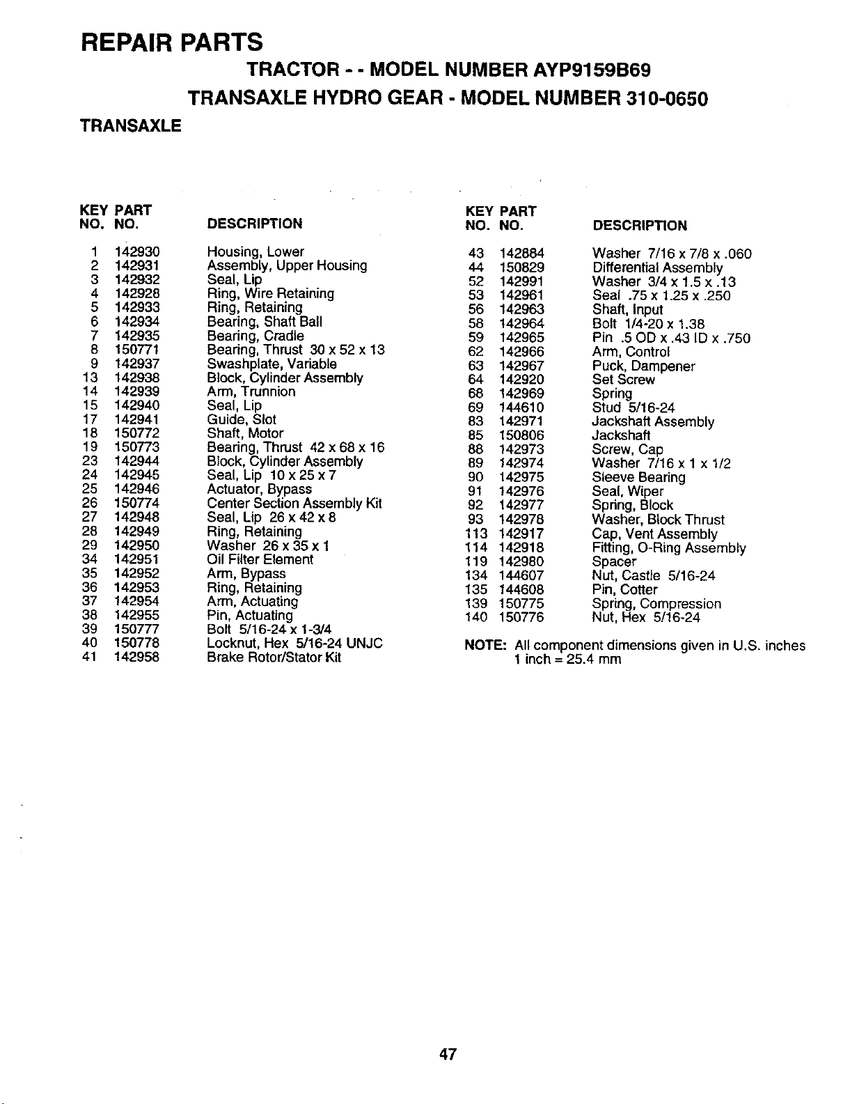
REPAIR PARTS
TRACTOR -- MODEL NUMBER AYP9159B69
TRANSAXLE HYDRO GEAR - MODEL NUMBER 310-0650
TRANSAXLE
KEY PART KEY PART
NO. NO. DESCRIPTION NO. NO. DESCRIPTION
1 142930 Housing, Lower 43 142884 Washer 7/16 x 7/8 x.06O
2 142931 Assembly, Upper Housing 44 150829 Differential Assembly
3 142932 Seal, Lip 52 142991 Washer 3/4 x 1.5 x.13
4 142928 Ring, Wire Retaining 53 142961 Seal .75 x 1.25 x .250
5 142933 Ring, Retaining 56 142963 Shaft, Input
6 142934 Bearing, Shaft Ball 58 142964 Bolt 1/4-20 x 1.38
7 142935 Bearing, Cradle 59 142965 Pin .50D x.43 ID x .750
8 150771 Bearing, Thrust 30 x 52 x 13 62 142966 Arm, Control
9 142937 Swashplate, Variable 63 142967 Puck, Dampener
13 142938 Block, Cylinder Assembly 64 142920 Set Screw
14 142939 Arm, Trunnion 68 142969 Spring
15 142940 Seal, Lip 69 144610 Stud 5/16-24
17 142941 Guide, Slot 83 142971 Jackshaft Assembly
18 150772 Shaft, Motor 85 150806 Jackshaft
19 150773 Bearing, Thrust 42 x 68 x 16 88 142973 Screw, Cap
23 142944 Block, Cylinder Assembly 89 142974 Washer 7/16 x 1 x 1/2
24 142945 Seal, Lip 10 x 25 x 7 90 142975 Sleeve Bearing
25 142946 Actuator, Bypass 91 142976 Seal, Wiper
26 150774 Center Section Assembly Kit 92 142977 Spring, Block
27 142948 Seal, Lip 26 x 42 x 8 93 142978 Washer, Block Thrust
28 142949 Ring, Retaining 113 142917 Cap, Vent Assembly
29 142950 Washer 26 x 35 x 1 114 142918 Fitting, O-Ring Assembly
34 142951 Oil Filter Element 119 142980 Spacer
35 142952 Arm, Bypass 134 144607 Nut, Castle 5/16-24
36 142953 Ring, Retaining 135 144608 Pin, Cotter
37 142954 Arm, Actuating 139 150775 Spring, Compression
38 142955 Pin, Actuating 140 150776 Nut, Hex 5/16-24
39 150777 Bolt 5/16-24 x 1-3/4
40 150778 Locknut, Hex 5/16-24 UNJC NOTE: All component dimensions given in U.S. inches
41 142958 Brake Rotor/StatorKit 1 inch = 25.4 mm
47
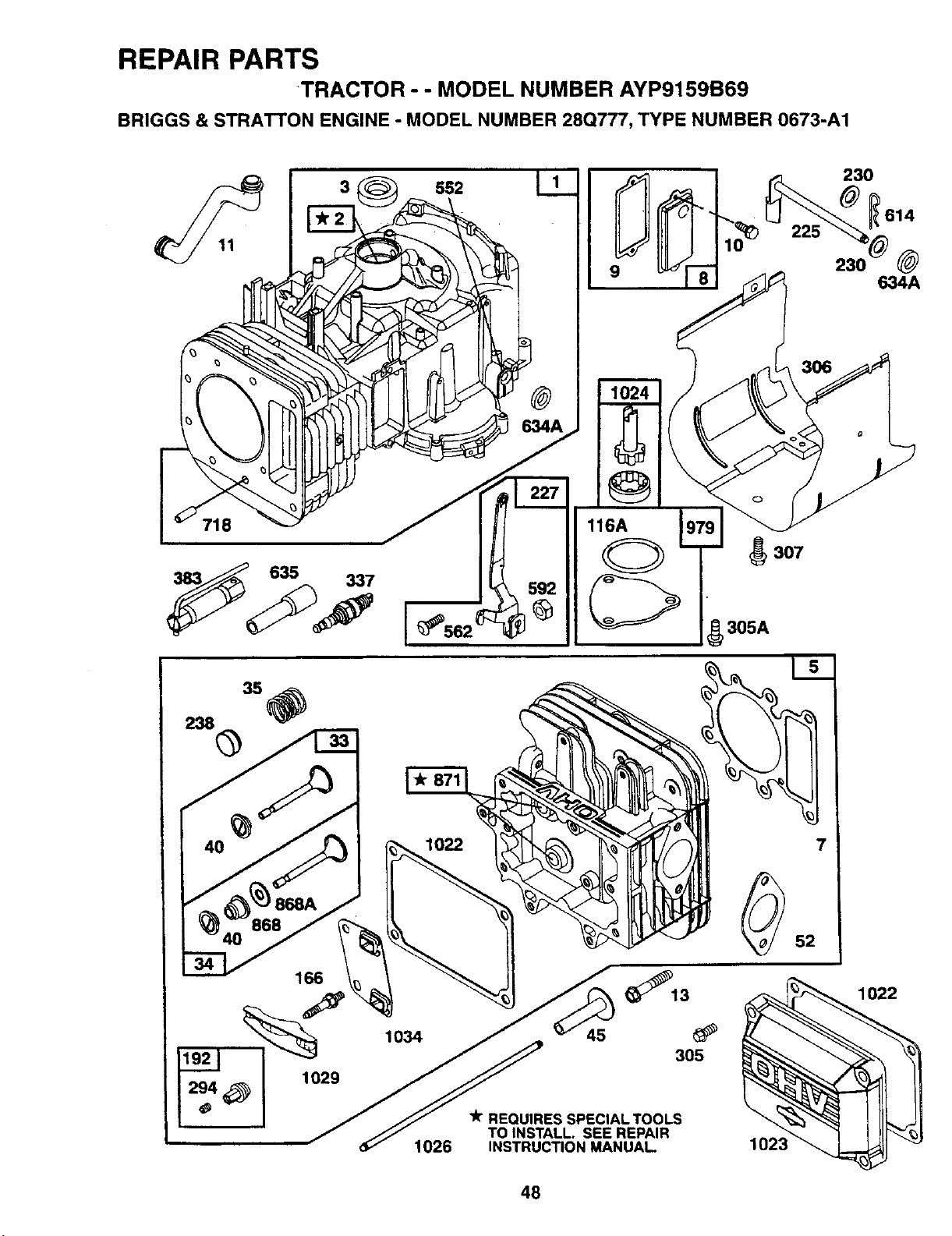
REPAIR PARTS
TRACTOR - - MODEL NUMBER AYP9159B69
BRIGGS & STRATTON ENGINE - MODEL NUMBER 28Q777, TYPE NUMBER 0673-A1
9
225
230
_614
@
634A
718
_307
305A
368A
868
166
1029
294 _
1022
1034 45
1026
7
REQUIRES SPECIAL TOOLS
TO INSTALL. SEE REPAIR
INSTRUCTION MANUAL
48
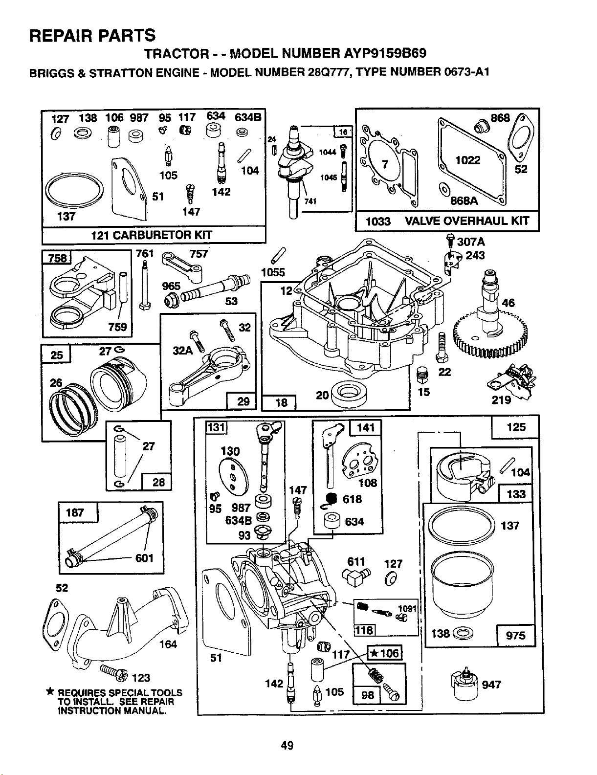
REPAIR PARTS
TRACTOR - - MODEL NUMBER AYP9159B69
BRIGGS & STRATTON ENGINE - MODEL NUMBER 28Q777, TYPE NUMBER 0673-A1
127 138 106 987 95 117 634 634B
121 CARBURETOR KIT
"A"REQUIRES SPECIALTOOLS
TO INSTALL. SEE REPAIR
INSTRUCTION MANUAL.
1022
1033 VALVE OVERHAUL KIT
49

SERVICE NOTES

SUGGESTED GUIDE FOR SIGHTING SLOPES FOR SAFE OPERATION
"r
SIGHTING _" _ ...CUT OU"
_LOPl _ _ _S
ONLY RIDE UP AND DOWN HILL,
NOT ACROSS HILL
SIGHT AND HOLD THIS LEVEL WITH
SKY LINE OR TREE.
15° MAX.
Operate your Tractor up and down the face of slopes (not
greater than 15°), never across the face. Make turns gradu-
ally to prevent tipping or loss of control. Exercise extreme
caution when changing direction on slopes.

HOW AND WHERE TO ORDER PARTS
You can identify your product correctly by looking at itsmodel number label which islocated under the seat.
1. A. Name the product that needs a part, for example: tractor.
B. State the product's model number andfactory number. These numbers appear on a label on the product.
2. List the description and part numberofthe partyou want. This manual shows drawings, descriptions, and part
numbers.
3. You may order from a participating Western Auto store. If you cannot do that, please order direct from:
Telephone: 1-800-633-8434
Westem Auto National Parts Center
2107 Grand Avenue
Kansas Ci_,MO 64108
154146 Rev. 1 05.16.96 JH/RH
PRINTED IN U.S.A.


