
OWNER MANUAL
DX1616
MATRIX AUDIO
PROCESSOR

2
TABLE OF CONTENTS
1. GENERAL INFORMATIONS ......................................................................................................................... 4
1.1 What’s in the Box ................................................................................................................................. 4
1.2 What you need to provide ................................................................................................................... 4
1.3 Safety information ................................................................................................................................ 4
2. Introduction and Description .................................................................................................................... 6
2.1 Front Panel ........................................................................................................................................... 6
2.2 Rear Panel ............................................................................................................................................. 7
2.3 Install the Solaro Console & Control software ..................................................................................... 8
2.4 Initial Device Connectivity .................................................................................................................... 9
2.5 DX1616 connected and powered up .................................................................................................. 12
3. Solaro Console Software ......................................................................................................................... 13
3.1 Network View ...................................................................................................................................... 13
3.2 TCP/IP Connection Trouble Shooting ................................................................................................ 14
3.3 Manual Assignment of IP Addresses To Multiple Devices – No DHCP: ............................................... 15
3.4 Firmware update to DX 1616 processor .............................................................................................. 17
3.5 Setting up Solaro Console & Control Software .................................................................................... 19
4. Solaro Control Software .......................................................................................................................... 20
4.1 Map Physical Devices – DX1616 and Control Panel............................................................................. 21
4.2 Switch to Online Mode: (Transfer/Save DSP design project to DX1616) ............................................ 22
4.3 Solaro Control - Programming ............................................................................................................. 25
4.3 Save and Creating Presets ................................................................................................................... 28
5. Technical Data ......................................................................................................................................... 31

3
Figure 1: Solaro “Network View” – Devices are ON ........................................................................................ 10
Figure 2: Device Setup – Network IP Addresses and DHCP ............................................................................. 11
Figure 3: DX1616 On Line ................................................................................................................................ 12
Figure 4: Solaro Console start up window ....................................................................................................... 13
Figure 5: Solaro Console “Network View” ....................................................................................................... 13
Figure 6: DX1616 Firmware update – starting the process ............................................................................. 17
Figure 7: Firmware update in process – Loading and verifying firmware ....................................................... 17
Figure 8: Firmware update in process – Do not power off the device ............................................................ 18
Figure 9: Firmware update – device not ready is shown ................................................................................ 18
Figure 10: Firmware update – process is finished ........................................................................................... 18
Figure 11: Open project file ............................................................................................................................. 19
Figure 12: Solaro Control – selecting network interface ................................................................................. 20
Figure 13: Mapping devices ............................................................................................................................. 21
Figure 14: Warning detected – Device not mapped ....................................................................................... 22
Figure 15: Load Design to Devices ................................................................................................................... 22
Figure 16: Online mode startup window ......................................................................................................... 23
Figure 17: Update device with project settings ............................................................................................... 23
Figure 18: Preparing devices to online control message................................................................................. 24
Figure 19: “Go back to Design Mode” – switching to Offline .......................................................................... 24
Figure 20: Copying settings to project file – yes ore not ................................................................................. 24
Figure 21: Solaro Control settings ................................................................................................................... 25
Figure 22: Solaro Control - empty workspace ................................................................................................ 26
Figure 23: Solaro Control - DX1616 and Solaro Control Overlapped ............................................................. 26
Figure 24: Solaro Control - DX1616 and Solaro Control - Programming ........................................................ 27
Figure 25: Switching back to Design Mode – Copying parameters to project file .......................................... 28
Figure 26: “Design Mode” – project view........................................................................................................ 28
Figure 27: “Design Mode” – Save Module Values to Preset ........................................................................... 29

4
1. GENERAL INFORMATIONS
1.1 What’s in the Box
• The DX1616 processor
• USB drive with Software, Project File, Quick Start Guide
• IEC socket detachable power cable
• Detachable 3.5mm Euro terminal block connectors
1.2 What you need to provide
• A Windows PC – 1GHz or higher processor
• Windows 10, 8 or 7 OS
• An Apple computer (Intel) with OSX operating system
• 500 MB of free storage space
• 16 Bit or higher colors
• 4GB RAM minimum
• Network (Ethernet) interface
• Ethernet cable (Cat5 or 6)
1.3 Safety information
1. READ THESE INSTRUCTIONS
All the safety and operating instructions should be read before the product is operated.
2. KEEP THESE INSTRUCTIONSThe safety and operating instructions should be retained for future reference.
3. HEED ALL WARNINGSAll warnings on the product and in the operating instructions should be adhered to.
4. FOLLOW ALL INSTRUCTIONSAll operating and use of instructions should be followed.
5. DO NOT USE THIS APPARATUS NEAR WATERDo not use the product near water. For example, near a
bathtub, washbowl, kitchen sink, or laundry tub, in a wet basement, or near a swimming pool, and the like.
6. CLEAN ONLY WITH DRY CLOTHUnplug the unit from the wall outlet before cleaning
7. DO NOT BLOCK ANY VENTILATION OPENINGSSlots and openings in the cabinet back or bottom are
provided for ventilation, to ensure reliable operation of the limit and to protect it from overheating. These
openings must not be blocked or covered. The openings should never be blocked by placing the product on
a bed, sofa, rug, or similar surface. This product should never be placed near or overa radiator or heat
source. This product should not be placed in a built-in installation such as a bookcase or rack unless proper
ventilation is provided or the manufacturer’s instructions have been adhered to.
8. DO NOT INSTALL NEAR ANY HEAT SOURCESThis Product should be situated away from heat sources such
as radiators, stoves, or other products (including amplifiers) that produces heat.

5
9. DO NOT DEFEAT THE SAFETY PURPOSE OF THE POLARIZED OR GROUNDING-TYPEPLUGA Polarized plug
has two blades with one wider than the other. A grounding-type plug has two blades and a third grounding
prong. The wide blade or the third prongs are provided for your safety. If the provided plug does not fit into
your outlet, consult an electrician for replacement of the obsolete outlet.
10. PROTECT THE POWER CORD FROM BEING WALKED ON OR PINCHED PARTICULARLY AT PLUGS,
CONVENIENCE RECEPTACLES, AND THE POINT WHERE THEY EXIT FROM THE APPARATUS.
11. ONLY USE ATTACHMENTS/ACCESSORIES SPECIFIED BY THE MANUFACTURER.
12. USE ONLY WITH CART, STAND, TRIPOD, BRACKET, OR TABLE SPECIFIED BY THE MANUFACTURER, OR SOLD
WITH THE APPARATUS. WHEN A CART IS USED, USE CAUTION WHEN MOVING THE CART/APPARATUS TO
AVOID INJURY FROM TIP-OVER.Do not place this unit on an unstable cart, stand, tripod, bracket, or table.
The unit may fall, causing serious injury to someone, and serious damage to the appliance. A unit and cart
combination should be moved with care. Quick stops, excessive force, and uneven surfaces may cause the
product and cart combination to overturn.
13. UNPLUG THIS APPARATUS DURING LIGHTNING STORMS OR WHEN UNUSED FOR LONG PERIODS OF TIME.
For added protection for this unit during a lightning storm, or when it is left unattended and unused for long
periods of time, unplug it from the wall outlet and disconnect the antenna or cable system. This will prevent
damage to the unit due to lightning and power line surges.
14. REFER ALL SERVICING TO QUALIFIED SERVICE PERSONNEL. SERVICING IS REQUIRED WHEN THE
APPARATUS HAS BEEN DAMAGED IN ANYWAY, SUCH AS WHEN THE POWER SUPPLY CORD OR PLUG IS
DAMAGED, LIQUID HAS BEEN SPILLED OR OBJECTS HAVE FALLEN INTO THE APPARATUS, THE APPARATUS
HAS BEEN EXPOSED TO RAIN OR MOISTURE, DOES NOT OPERATE NORMALLY, OR HAS BEEN DROPPED.
15. WARNING: TO REDUCE THE RISK OF FIRE OR ELECTRIC SHOCK, DO NOT EXPOSE THIS APPARATUS TO RAIN
OR MOISTURE.
16. APPARATUS SHALL NOT BE EXPOSED TO DRIPPING OR SPLASHING AND NO OBJECTS FILLED WITH
LIQUIDS, SUCH AS VASES, SHALL BE PLACED ON THE APPARATUS.

6
2. Introduction and Description
Thank you from everyone here at RCF and thank you for purchasing DX 1616 digital processor.Since DX 1616
is setup and controlled by a host computer via Ethernet it is important that we get you connected and up
and running as quickly and easily as possible.
Note: this manual is dedicated to getting the DX 1616 processor and the Solaro Console and Control software
connected and operating.
In our website you can download single projects for different purposes. Every project will have its own
manual because the device can be used in different way in accord with a given project.
For this reason we suggest first read this manual and second read the manual related to the project that you
are using.
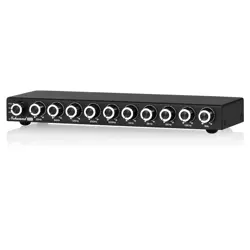
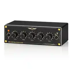
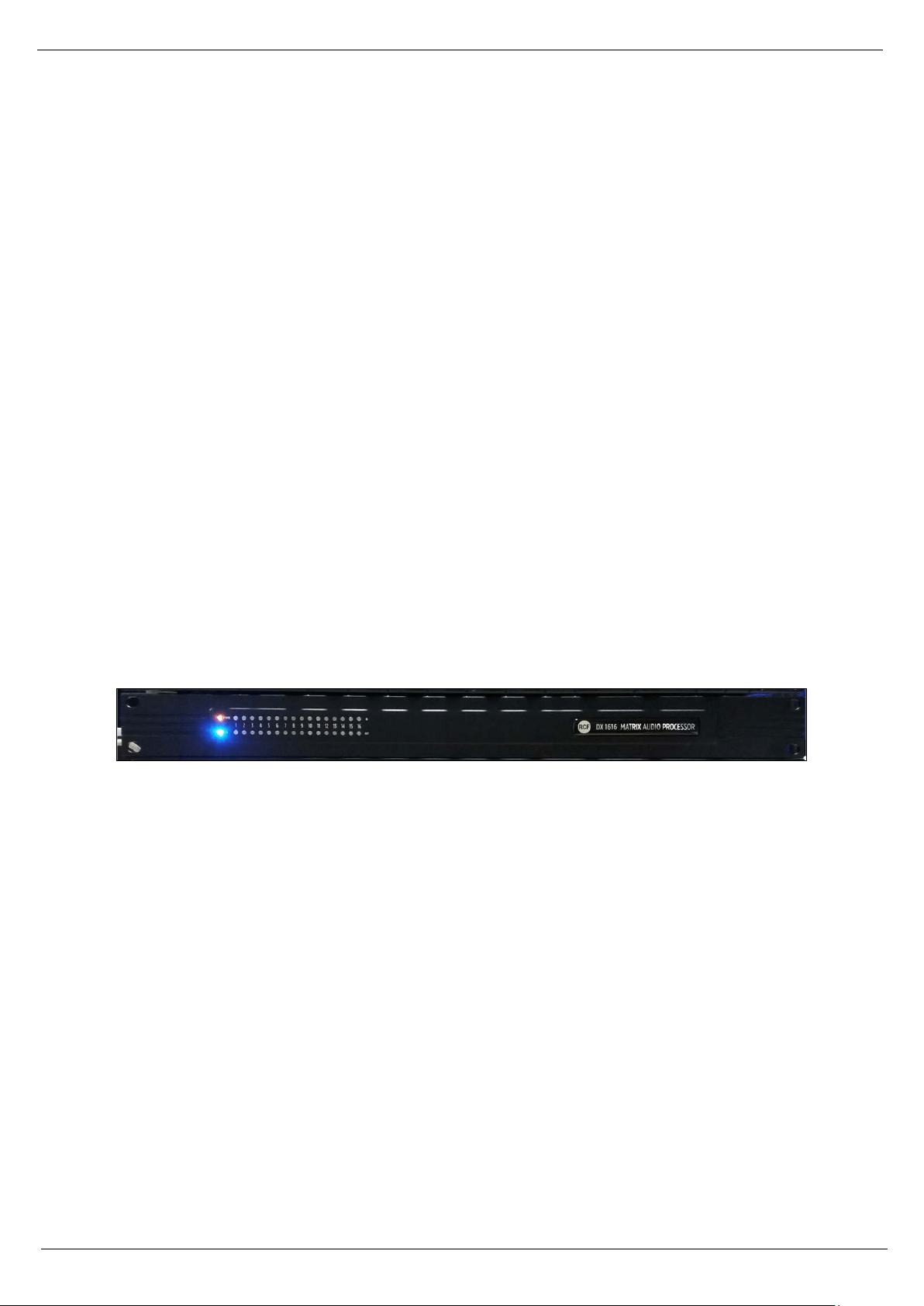
2.1 Front Panel
Power Status LED
A blue Power Status LED will light to notify you that the DX 1616 device is connected to a power source and
switched to the ‘On’ position.
Network Status LED
When the processor has an Ethernet cable / network cable connected the orange Network status LED on the
front of the processor will light - once the processor initializes. If there is no Ethernet / network cable
attached it remains off.
Note: When the Network status LED is on it does not mean that you have established a Network Connection
– only that an Ethernet or network cable is connected to the processor. Proper Network Connection and
Operation is indicated/displayed only in the software’s “Network View” page (see the Network View &
Connection section of this guide).
When the processor and software are connected and communicating the orange Network status
light will flash
Input/Output Signal Indicators
Each Input and Output channel has a dual colour LED signal indicator. Green for signal present at -40 dBu and
Red at +17 dBu at the advent of analog clipping.

7
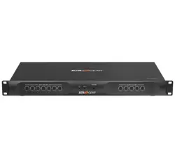
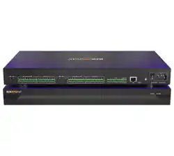
2.2 Rear Panel
Power On/Off Switch
Fuse Compartment
Should you need to replace the fuse use a T-Series 2.5A-250V fuse. Ensure power to the device is
disconnected when replacing the fuse.
Power Input Connector
Insert the IEC plug connector end of the supplied cable into the rear panel of the DX 1616. Connect the
AC end of the cord into an AC power source of the correct voltage and frequency (100-240 VAC, 50/60
Hz).
Ethernet Connector
DX 1616 utilizes a TCP protocol for communication with the host PC running the Console software. The
port is a standard RJ45 (Ethernet) jack.
IP Reset Button.
See IP reset push button / Reset Processor Network Settings (DHCP not available) section in this guide.
Logic Control Input/Output Port
Utilizing twisted pair wire with an attached terminal block, you can use external signals to control
parameters such as triggering presets within Console.
Analog Line Outputs
Euro/Phoenix style terminal block output connections utilizing 3.5mm terminal block connectors
(included). Use balanced, shielded audio cabling. DX 1616 has sixteen (16) outputs.
Analog Mic/Line Inputs
Euro/Phoenix style terminal block input connections utilizing 3.5mm terminal block connectors (included).
Use balanced, shielded audio cabling. DX 1616 has sixteen (16) switchable Mic/Line inputs with 48V
phantom power. Note: Mic inputs are only available in channel 15 and 16 (please refer to the default
RCF DX1616 project file).
Network Audio I/O
DX 1616 include two RJ45 Dante enabled network audio connectors (not to be confused with the Ethernet
connector). 16 x16 I/O channels on one RJ45 connector/cable – one RJ45 for redundancy.

8
2.3 Install the Solaro Console & Control software
The USB drive included with each processor includes a full copy of the DX 1616’s software. You can download
the Solaro Console and Control software from RCF web site www.rcf.it
Note: Solaro Control App for iPad/ iOS please visit Apple App Store and search for “Solaro Control”
Windows users
When installing the Console software via our web site and where your windows PC software does not include
Microsoft’s .net framework component - your PC will use the Internet to secure a copy and continue the
installation.
Note: The Microsoft installation program/process remembers what location you installed from - the first time
you load the Console software into your computer. This can cause issues if you try and load a new software
Version (update) from a different location than the location originally used to load the Console software into
your computer (USB, Internet Download, etc).
Solution: Simply un-install the old Console software version in your computers control panel before you
update your software version each time. You won’t have any update issues and you won’t have to remember
what location you loaded the software from previously or what the source was - USB, Internet, etc.
Make sure the Console Software version is the latest version (see “About” menu vs. the web site). Make sure
the processors Firmware version is compatible with software (view device firmware version in Network
View).
Note: Solaro Control App for iPad/ iOS please visit Apple App Store and search for “Solaro Control”
Firewall – allow access !
If you have a personal Firewall setup on your computer, a Firewall popup window might be displayed during
the software installation to ask whether users want to “Block” or “Allow” Console from accessing the
network. Select “Allow” to continue installation.
Once installed and working – close the Console software for now until you are instructed to open it again.

9
Download and save DX1616 project files
These are the pre-designed DX1616 device designs and DSP schematics that you will select from to use in
your Solaro Console software and DX 1616 processor.
Before you begin working with the Solaro Console software and your DX1616 processor - visit RCF web site
at www.rcf.it and save to a folder in your computer the DX 1616 project files (.pjxml files).
2.4 Initial Device Connectivity
The DX1616 runs on a network based infrastructure and are configured and controlled by a host computer
via Ethernet using the Solaro Console software. A network connection can be made between your computer
and DX1616 via DHCP enabled router (recommended) or non-DHCP enabled connection.
The primary difference between these two connection methods is the automatic IP address assignment /
management that DHCP provides.
Note: Available DHCP is the recommended connection method!
A DHCP enabled Router, Server, or Router/Switch
The DX1616 processor device boots up with DHCP enabled by default so with DHCP enabled routers and
servers DX1616 will automatically obtain an IP address upon connection and power up.
Note: This may take a minute or two as the devices look for DHCP to obtain their IP address!
A Non-DHCP enabled direct connection or indirectly via an Ethernet switch.
When the processor is connected directly to a computer or indirectly via a switch or hub and DHCP is not
available to assign IP addresses - the connection process is not automatic.
A Single Processor or Device in the Network Only - No DHCP Available
Once no DHCP is detected - a single direct or indirectly connected processor/device will either try to connect
using the IP address last assigned and stored in the device or attempt to revert to is default IP address of
169.254.128.128. Under some conditions the processor/device might refuse to relinquish its stored IP
address or revert to its default IP address and thus refuse to connect. To simplify and speed this non-DHCP
enabled connection we recommend - that before you power up your processor/device you should Reset the
processor/device to its Default IP Address using the IP Reset Button on the rear of the device.
Resetting the processor to its default IP address of 169.254.128.128 will have you connecting directly quickly
and without problems when no DHCP is available.
Please see - IP Reset Push Button / Reset Processor Network Settings instructions if you are creating a non-
DHCP direct or indirect connection.
10
Note: Most modern computers can now detect a direct connection so you can use a straight through Ethernet
cable for the direct connection (if there is a direct connection issue that persists then you might try a
crossover type Ethernet cable).
Note: Your PC should be set to “Obtain IP Address Automatically” – which is the common default setting in
most PC’s.
IP reset push button / Reset Processor Network Settings (DHCP not available)
Follow these instructions prior to powering up the processor and opening the Solaro Console software.
(a) At the rear of the processor you will see a small, round, recessed push button labeled “IP Reset”- just to
the right of the Ethernet connector (looking from the back). You are able to push this reset push-button
inward using the point of a pen or a small pointed object.
(b) Press the IP Reset push button inward and while holding it pushed in power up the processor device.
(c) Wait 5 seconds after power up and then release the IP Reset push button.
(d) Wait for the processor to power up completely (this will take a minute or so as it initializes and sets its
default IP address). When complete the Network status LED will light and remain on.
Note: This may take a minute or two as the devices to obtain their IP address!
Note: After resetting the IP, it is strongly recommended to close and re-launch Solaro Console & Control
software!
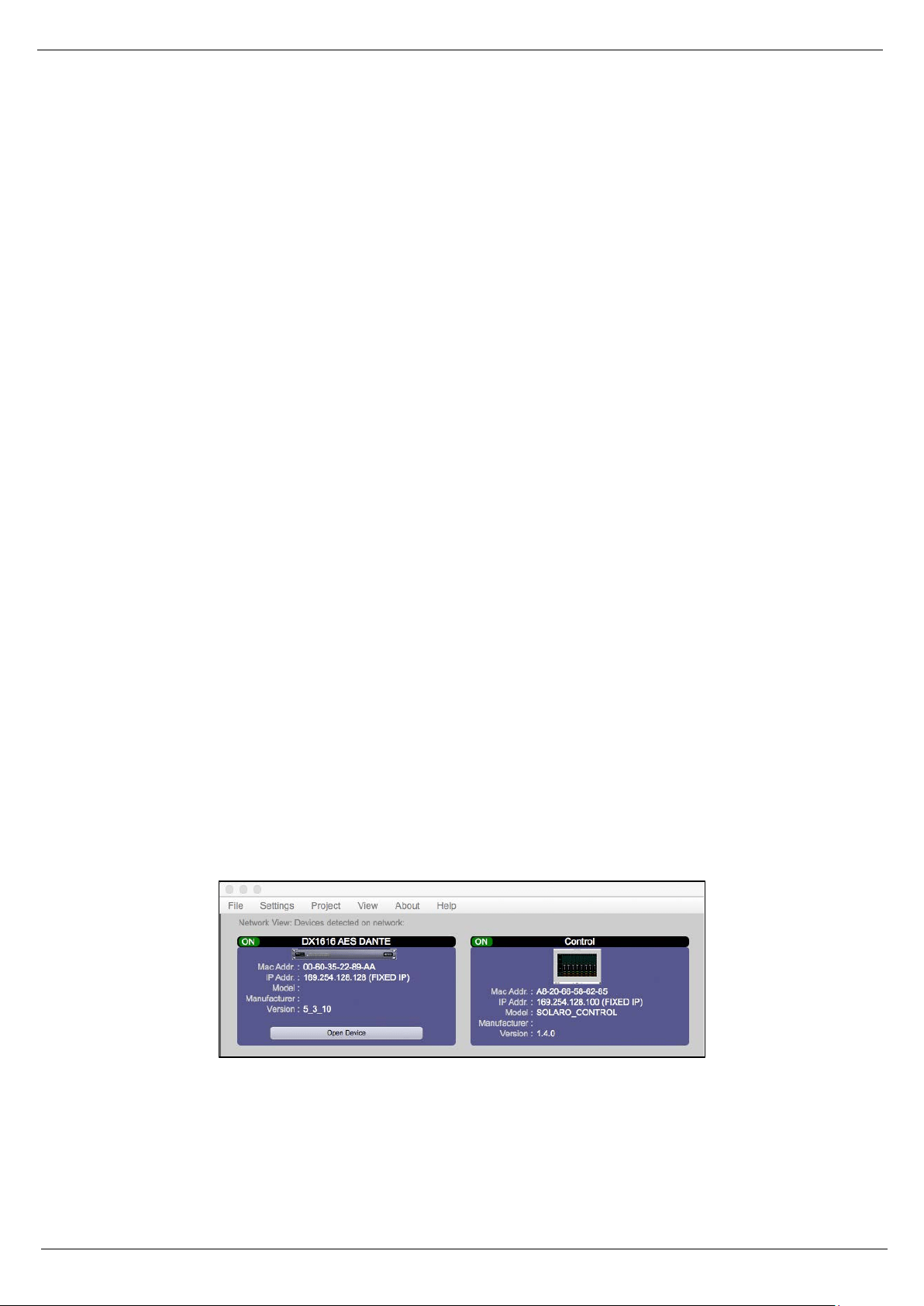
(e) Double check in Solaro Console software “network view” the IP-addresses of DX1616 and “Control”
Figure 1: Solaro “Network View” – Devices are ON
(f) In the case that the IP Address is not shown correctly (i.e. DHCP, instead of fixed IP), please launch Solaro
Console or Control software again and be sure to select the correct network interface settings in the first
menu while the application is starting!
11
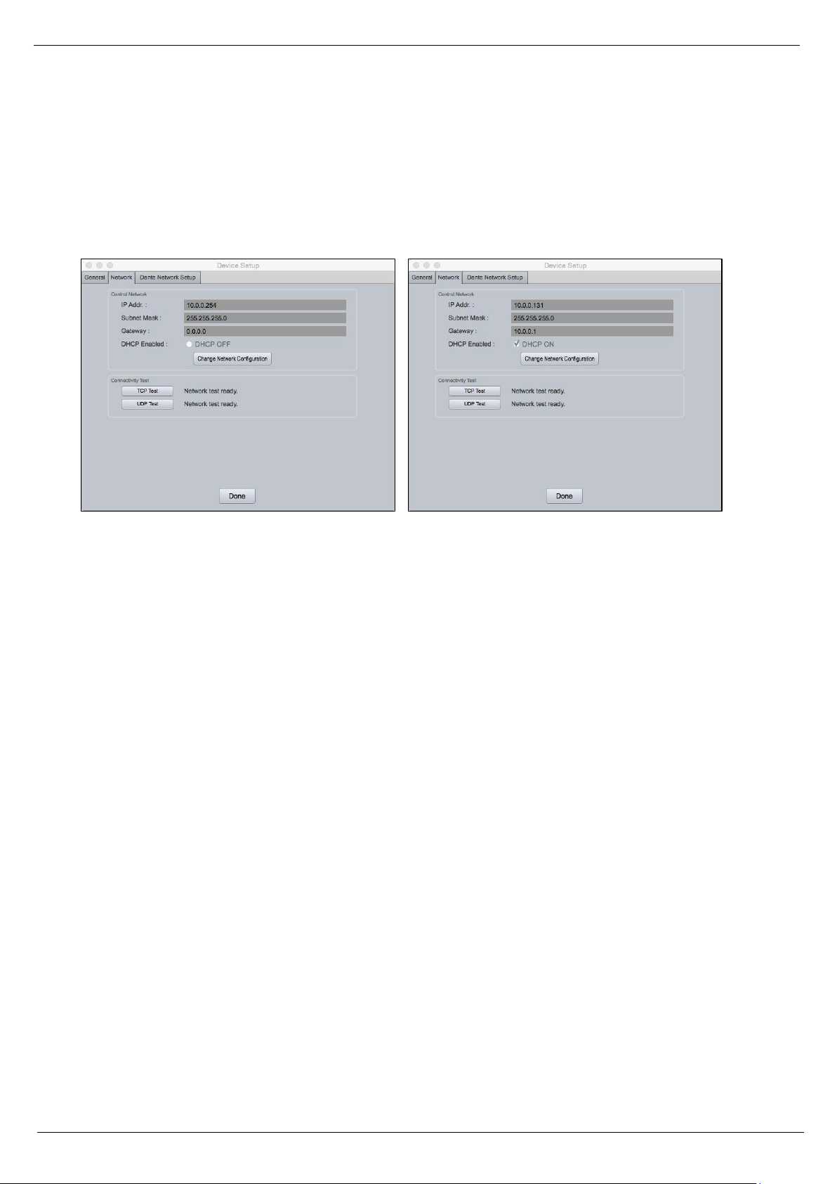
IP reset with software
Each connected device also has a reset function by software. In Network View of Solaro Console software,
right click the device and select device setup > network: “Change network configuration” like shown below.
Note: If DX1616 is not responding correctly after changing IP Address, please proceed a power cycle of
DX1616 and wait for re-booting.
Figure 2: Device Setup – Network IP Addresses and DHCP
Multiple Processor Devices Connected to the Network – No DHCP Available
Where you will be connecting multiple DX1616 processors in your network and DHCP is not available, the
user will have to manually assign unique static IP addresses to each processor or device.See – manual
assignment of IP addresses.
12
2.5 DX1616 connected and powered up
With your processor device/s connected as a network or directly to your computer, power on all devices.
(a) On power up the processors Power Status LED will light.
(b) If the processor has an Ethernet cable / network cable connected the Network Status LED on the front of
the processor will light - once the processor initializes. If there is no Ethernet / network cable attached it will
remain off.
Note: This does not mean that you have established a network connection – only that an Ethernet or network
cable is connected to the processor. Proper Network Connection and Operation is indicated/displayed only
in the software’s Network View page – see Network View & Connection.
(c) Upon being powered up the processor will search for a DHCP router or server to obtain an IP address. If
it locates DHCP it will connect quickly. If you are using a direct or indirect Non-DHCP connection you will have
followed the instructions to connect to a single processor or multiple processors – where DHCP is not
available.
(d) When the processor and software are connected and commands are being sent to the device the
Network Status LED will flash
Figure 3: DX1616 On Line
13
3. Solaro Console Software
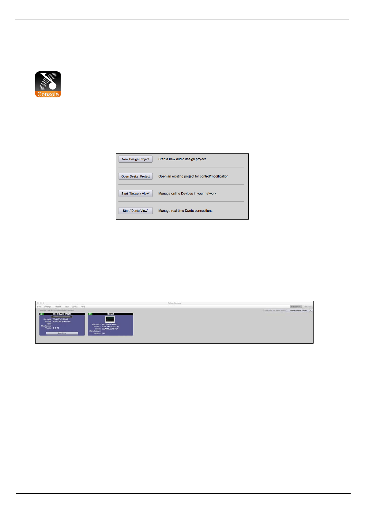
Upon opening the Solaro Console software you will be shown the “Solaro Console Startup” window. It
provides 4 possible selections: “New Design Project”, “Open Design Project”, Start “Network View” (Network
View will also be available to you as a separate button located at the top right of the Project View/Design
Mode work area page. The fourth selection is Start “Dante View” to manage real time Dante connections.
Figure 4: Solaro Console start up window
3.1 Network View
(a) Click Start “Network View” from the Solaro Console Startup window shown above. The Network View
displays all DX1616 and control devices connected to the network plus information such as the processor
device model, a green, yellow or red network connection indicator, the IP address, and the devices Firmware
version.
Figure 5: Solaro Console “Network View”
(b) In Network View you should now see your DX1616 connected to the network router block and the
Network Connection Indicator to the left of the processor device model should be Green/On (meaning it is
connected and operational).
(c) Firmware version: Any device firmware / software incompatibility will be indicated in Network View with
either a Red warning symbol (connected but firmware is not compatible - must upgrade device firmware) or
a Yellow symbol (connected and may function but firmware is not a recommended version). See Firmware
Upgrade.

14
(d) If your processor and software have tot connected properly you will see a Red or Yellow connection
indicator to the left of the processor or device model in Network View indicating a connection or operational
problem.
Network Connection Indicators
• Green (On) - Connected and operational.
• Yellow – Connected but Not Operational.
• Red (Off) - The processor is offline
• Not connected – no communication between the Solaro Console software and the DX1616
processor. Check cables and connections.
Note: This could be a temporary offline interruption if the processor is busy performing a firmware
upgrade, re-booting, searching for DHCP or defaulting to its default IP address.
3.2 TCP/IP Connection Trouble Shooting
While in “Network View” if there is a Yellow network connection indicator next to the processor device model
the device is connected/online - but Not Ready / Not Operational.
The three most common reasons for this Yellow connection indicator is the result of
(a) A non- DHCP connection where multiple processors are in use and each device needs a unique IP address
manually assigned to it
(b) Where a non-DHCP direct or indirectly connected - single processor device is not reverting to its default
IP address and/or is holding onto its previous address and
(c) Software/Firmware incompatibility.
(d) Your computer is featuring more than one network interface
Solutions
(a) See instructions– manual assignment of IP addresses
(b) Reset the processor to its default IP address
(c) Check device firmware version in Network View & perform a processor firmware upgrade.
(d) If you computer is featuring more than one network interfaces, i.e. LAN port and WiFi: Make sure, that
both interfaces do NOT have the same IP range! If you do not want to change the IP addresses, just deactivate
the not needed network interface and re-launch Solaro Console software.
Those connection solutions resolve 99% of any Yellow indicator connection issues but to assist further, when
the indicator is Yellow you can hover your cursor over the device and there is a pop-up Tooltip message to
tell you the kind of issues it has detected.

15
A few message and solution examples below.
Message: Device not ready.
Solution: Wait a minute or two till the device is ready and it should then connect and the indicator turn Green
if successful. If the indicator remains Yellow, close the Solaro Console software and then re-open or reset
the processor.
Message: Device Schematic Not ready.
Solution: The processor has already been loaded with a DSP design. Give the connection process a minute
to connect and if it does not connect close the Solaro Console software, open it again, select Start “Network
View” and you should now see that the processor is connected and operational - as indicated by the Green
network connection indicator to the left of the processor device model.Solution: If not connected – reset
the processor – see IP reset push button / Reset Processor Network Settings (DHCP not available) or IP reset
with software.
Message: DSP Processing Error.
Solution: This could be a bad DSP Design schematic. You may need to reload the DSP schematic and restart
and/or restart device to reset its DSP chip.
Message: Error in Firmware Upgrade.
Solution: It will print out an error code when you hover your cursor over the device in Network View (Do
Firmware Upgrade again).
3.3 Manual Assignment of IP Addresses To Multiple Devices – No DHCP:
Unique, manually assigned/static IP addresses are required for each processor or device. (Each processor or
device indirectly connected to the PC via a network switch or hub)
Note: Make sure your computer is set to “Obtain IP Address Automatically”.
Note: We will set your computer’s static IP Address after changing the IP Addresses on all the processors and
devices first!
To manually assign static IP addresses to multiple processors and devices,
(a) Connect device number one directly to your PC, reset its IP address (IP Reset) and establish a connection
between the device and your PC/Solaro Console software.

16
(b) Next, in Network View - right click the connected processor or device and select “Device Setup”. In the
Network Properties window as shown at the right - select “Change Network Configuration” in order to disable
DHCP and to insert IP addresses manually (it also provides two built in test procedures, device security, and
device information).
(c) With the DHCP button disabled, assign the unique IP Address of 192.168.1.X to the first processor device
– where X is a unique number between 0 & 255.
(d) When finished – Select “Apply” to save changes and then “Done” to exit.
(e) Complete steps (a) thru (d) above for each subsequent processor or device so that each is assigned its
own unique static IP address (example – might be 192.168.1.180 / 181/ 182/ etc.
(f) Note: Your devices will appear Offline until you assign a static IP address for your PC as described below.
(g) Once all processors and devices have their own unique IP address we will do the same for your PC.
A Static IP Address for your Computer - Multiple Devices – No DHCP:
In this section, we will be navigating through Microsoft Windows to determine your home networking
information as it applies to manually assigning a unique static IP address to your computer.
(a) The first step is to open the 'Start Menu' and select Control Panel.
(b) Click View Network Status and Tasks under the Network and Internet header as shown at the right.
(c) Click on Change adapter settings on the left most tab.
(d) Left-Click on Local Area Connection and click the Properties button. Select Internet Protocol Version 4
(TCP/IPv4) then click Properties to access the manual IP settings.
(e) Set up your IP address to be 192.168.1.X where the X can be any value from 0 – 255 – but unique from
the other devices that you already manually assigned unique IP addresses to.
(f) Use the following settings for your PC’s unique static address: IP Address: 192.168.1.X (Example – IP might
be 192.168.1.185 based on my Subnet Mask: 255.255.255.0 unique device addresses above) Gateway:
192.168.1.1 DNS Servers: 192.168.1.1
17
(g) If you set up your devices as per steps above, you will now see them appear online and connected in
Network View in the Solaro Console software.
3.4 Firmware update to DX 1616 processor
Once you have the processor device and the Solaro Console software connected and operational and before
you start work on a DSP design project - make sure your processor has the latest firmware installed
(www.rcf.it – verify, download latest firmware, save file to your PC and proceed below with firmware upgrade
procedure if required).
Note: You must not disrupt power during the Firmware Upgrade process!
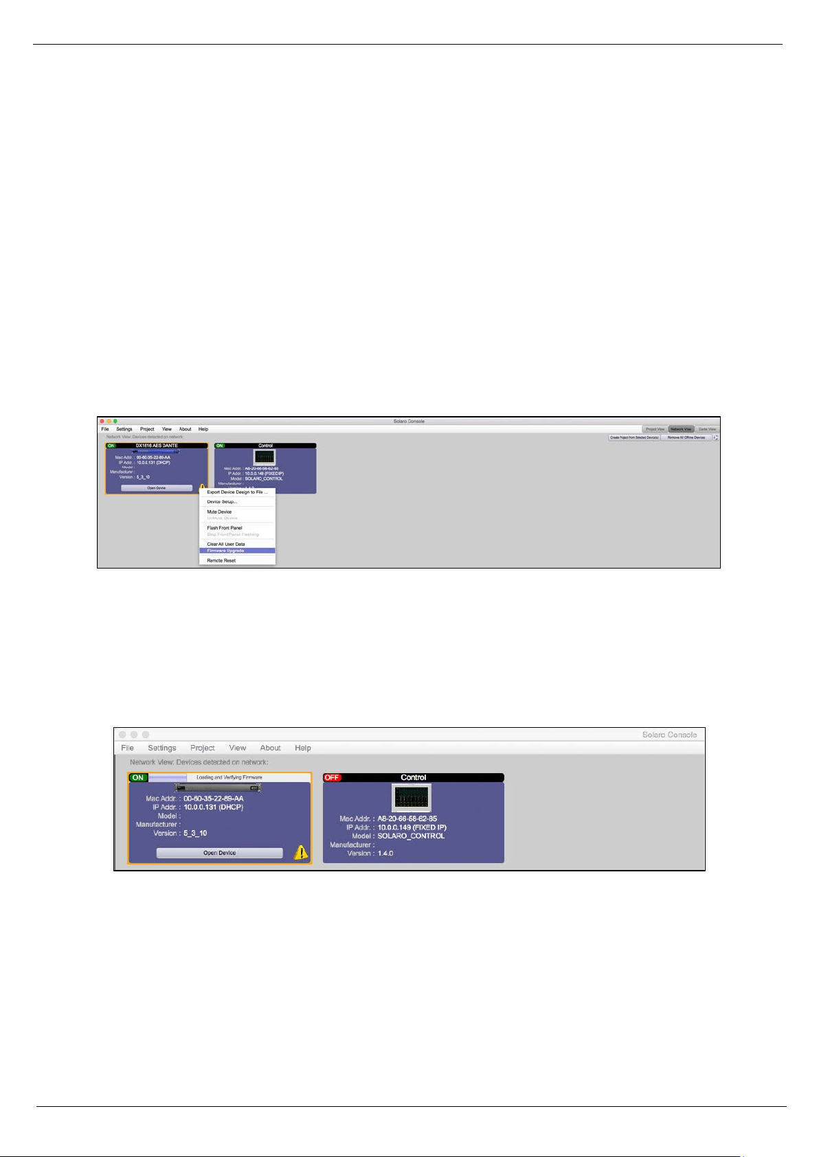
(a) In Network View – Right click the device, Select “Firmware Upgrade” from the menu and follow the
instructions.
Figure 6: DX1616 Firmware update – starting the process
(b) As indicated during the firmware upgrade procedure – a firmware upgrade will erase all saved data on
the device. Thus perform this procedure before you load a complete DSP Design Project into the processor
device (or re-transfer/save a saved project design file to the processor device after the processor firmware
upgrade is complete).
Figure 7: Firmware update in process – Loading and verifying firmware
(c) The status of the firmware update is shown in a horizontal bar. If that bar stops for long time (>5min) and
does not continue, just start with the firmware update process again!
Note: during the firmware update process the DX1616 switches automatically the internal relay on and off.
This is normal!
18
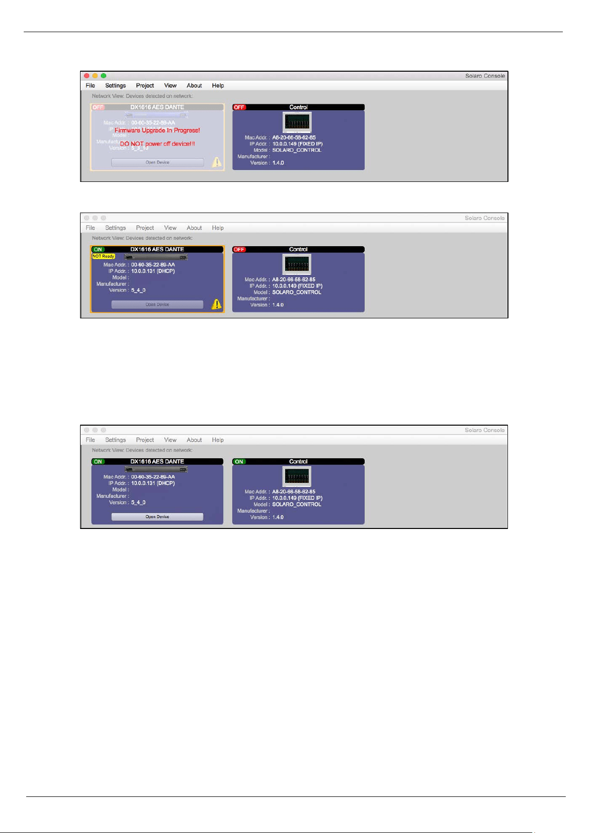
Figure 8: Firmware update in process – Do not power off the device
Figure 9: Firmware update – device not ready is shown
Note: If the network view shows “Device NOT ready”, you have to load your project file into the updated
DX1616 and switch to online mode like described in the chapter: Open Project (project file).
(d) Now the update process is finished
Figure 10: Firmware update – process is finished
Note: Depending on the firmware update: If there is still the yellow exclamation mark, please launch Solaro
Console again or proceed a power cycle on DX1616.
19
3.5 Setting up Solaro Console & Control Software
In the following procedure the DX1616 is connected and operational!
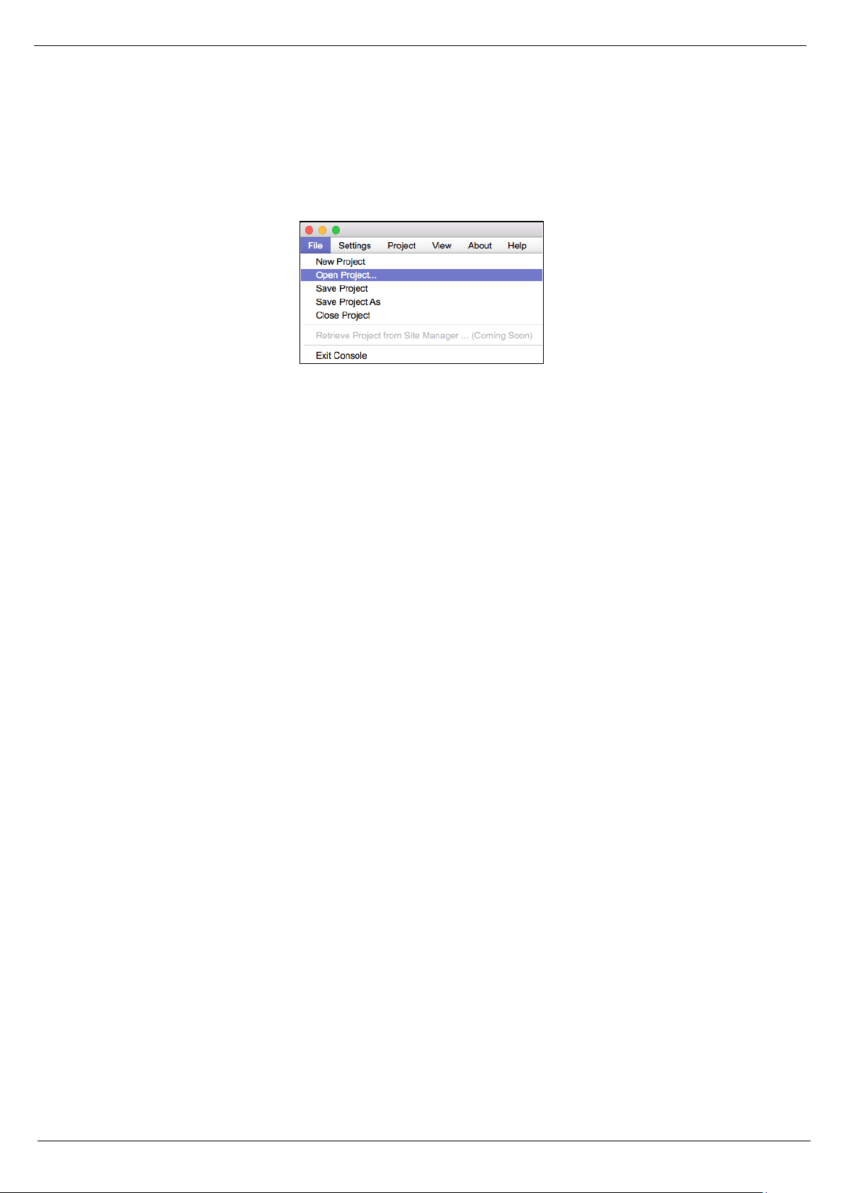
Open Project as selected under “File” is where you open or access previously worked on and saved DSP design
project files.
Figure 11: Open project file
(a) Select “Save Project As” under the File menu at the top left of the application to name and save your
design project and “Save Project” to save as you work.
Note: This saves the DSP design project you are working on to your PC (not to the physical processor device).
See “Switch to Online Mode” below to accomplish that.
(b) Note: We recommend that you save the project file twice. Once to create or keep the RCF factory Master
File (*.pjxml) and a second time to create a user work file. Continue working with the Work File and keep the
Master File as reference or fall back.
20
4. Solaro Control Software
The DX 1616 processor shall be remotely controlled using Solaro Console software GUI and with your PC/Mac
or Android, iOS device.
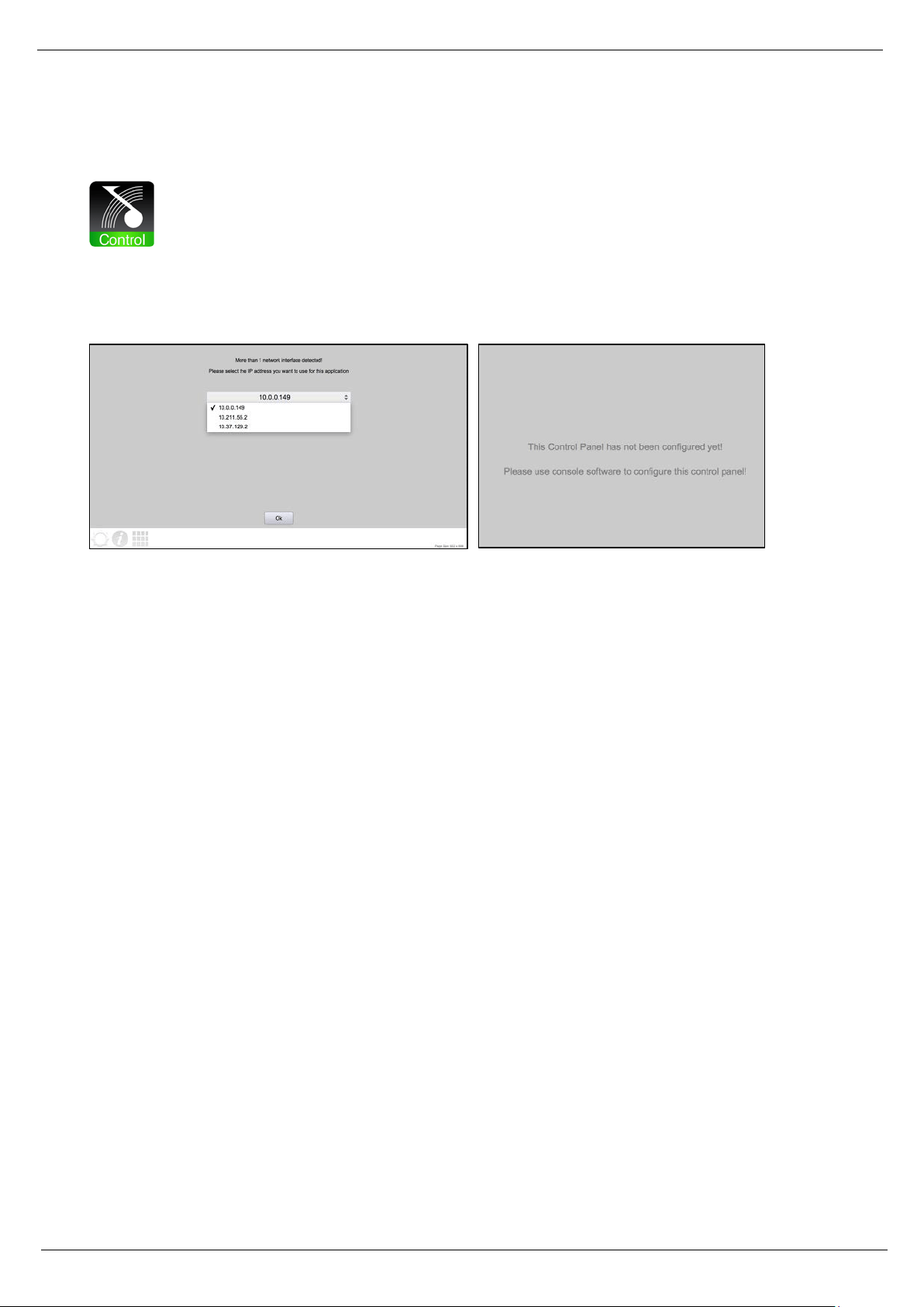
Figure 12: Solaro Control – selecting network interface
If several network adapters are found, select the IP Address, which fits to your network (project).
Note: If you computer is featuring more than one network interfaces, i.e. LAN port and WiFi: Make sure, that
both interfaces do NOT have the same IP range! This will cause trouble in the Control app’s communication.
If you do not want to change the IP addresses, just deactivate the not needed network interface.
When launching for the very first time, the message “This Control Panel has not been configured yet” is
shown. This is correct and not a mal function. Please proceed the mapping process like described below in
the chapter “map physical devices”.
Note: To map the “Control” panel (your remote computer or iPad) keep Solaro Control running on your
computer/ iPad! Your Computer must be connected to the same network like DX1616. If so, in Solaro Console
software your remote computers’ Mac Address will be available to map physical devices.
21
4.1 Map Physical Devices – DX1616 and Control Panel
Next, with the DX 1616 processor module for this application placed in the Project View/Design Mode work
area (and when the processor device is connected to the Solaro Console software) you need to map the DX
1616’s software processor module in the work area with the actual physical DX 1616 processor device that
is connected to the PC.
Note: The mapping process is only need if:
• A DX1616 and its control devices (PC, iPad, Phone) are used for the very first time in a network
• The hardware was changed (a new DX1616, a new PC, A new iPad)
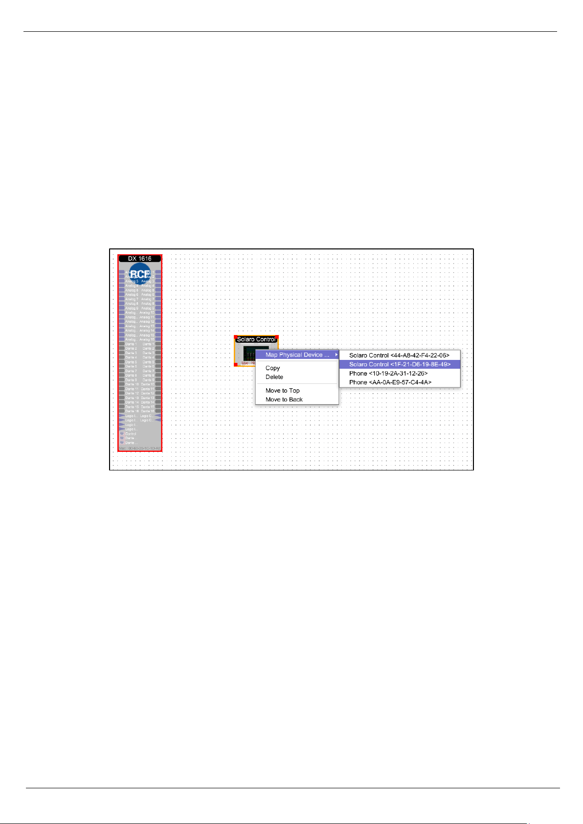
Figure 13: Mapping devices
(a) To Map DX1616, right click the DX1616 processor in the work area. Select “Map Physical Device” and
select the DX1616 you are working with from the drop down list.
(b) To Map your Control Panel, right click the Control Panel in the work area. Select “Map Physical Device”
and select the proper device’s Name/Mac Address you are working with from the drop down list.
Note: The physical Control Panel device can be a PC, Apple computer, iPad or Android tablet. The screen
resolution must be minimum 1024 x 720px for iPad or 1280 x 900px native resolution for computer displays.
We recommend true Full HD resolution with 1920 x 1080px.
22
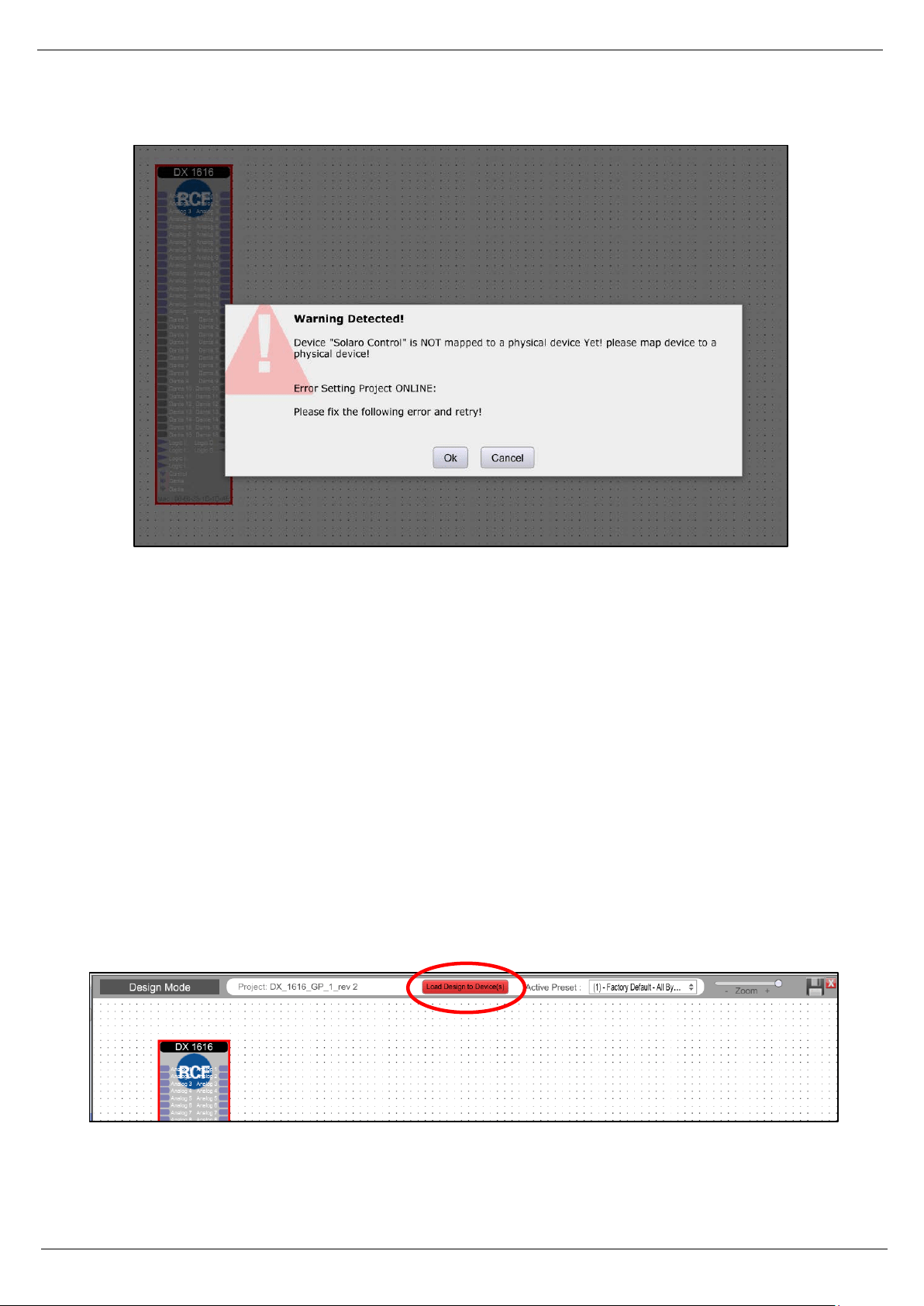
Warning detected, device “xxxx” NOT mapped
Figure 14: Warning detected – Device not mapped
This message will pop up, if your control device panel is not mapped, or you have a second panel (i.e. for
ipad) which is not mapped.
If you are not going to use the second control panel (ipad), you have to delete this control panel in your
project file.
4.2 Switch to Online Mode: (Transfer/Save DSP design project to DX1616)
After successful mapping of the devices you are ready to switch to online mode:
(a) Click the red “Load Design To Device” button at the top of the Project View / Design Mode work area
page – as shown below (not visible if a network interface is not detected – you are working Offline)
Figure 15: Load Design to Devices
23
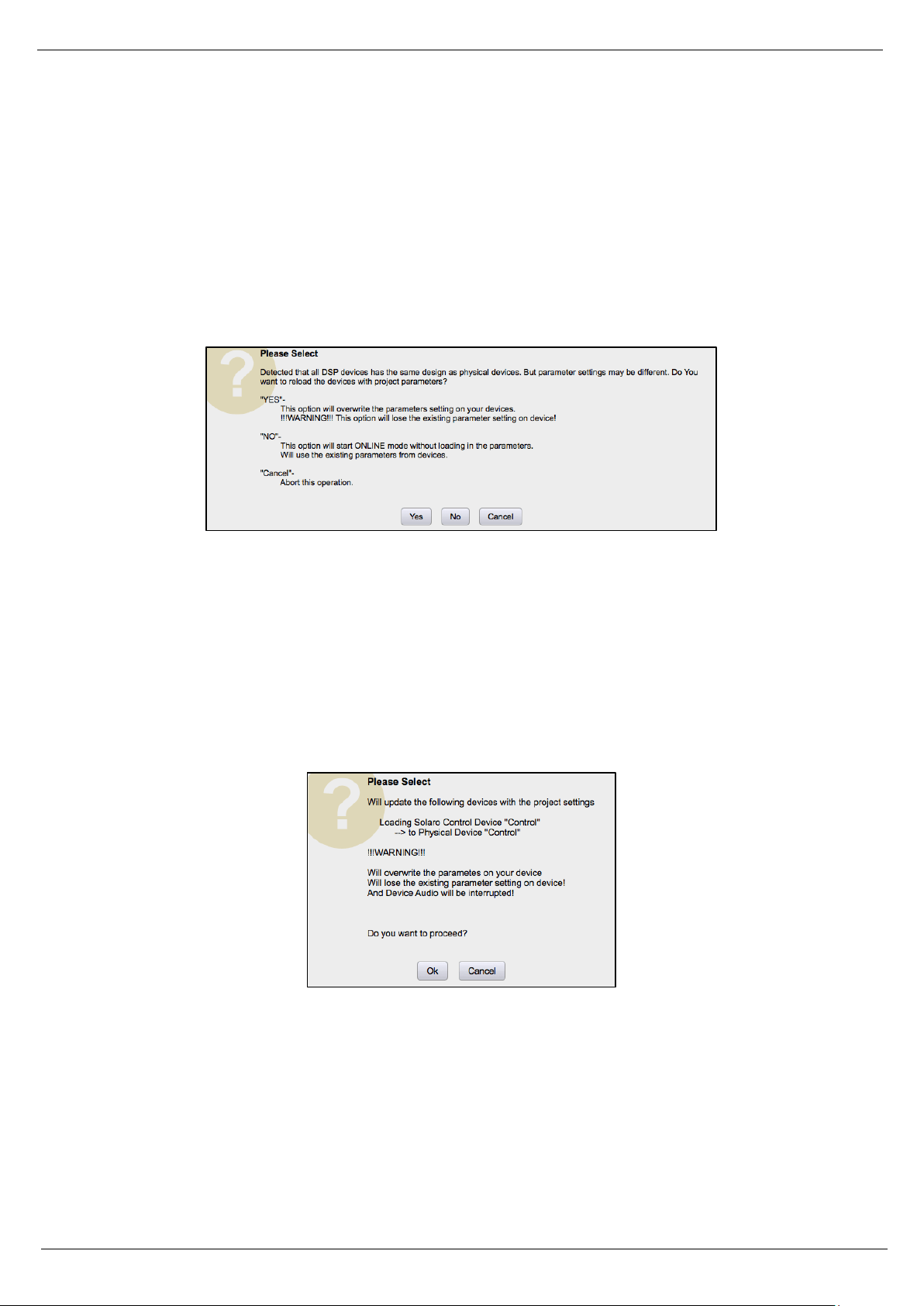
(b) You will be asked if you want to load the settings to the DX1616 (“device”).
“Yes”: when you load for the very first time the project file settings to the DX1616 you have to confirm with
“yes”.
“No”: Select “No” if you want to switch to Online Mode and still want to use the current (formally loaded
design project) parameter settings in DX1616.
Figure 16: Online mode startup window
After confirming with “No” a second message box might open and your confirmation with “Ok” is needed to
proceed with the process.
Note: Please be not confused. You will get connected with all the last parameter settings done in DX1616
before. Important is, that you selected “No” in the first message box “No = This option will start online mode
without loading in the parameters. Will use the existing parameters from device”.
Figure 17: Update device with project settings
Note: Any problems – check auto warning messages in Network View regarding any Firmware Incompatibility
with Software (will not load your design into device if any incompatibility).
(c) the procedure “Load Design to Devices” may take 1minute in total depending on the number of presets
included in the project file. On top of the screen you will see a status bar given the percentage progress.
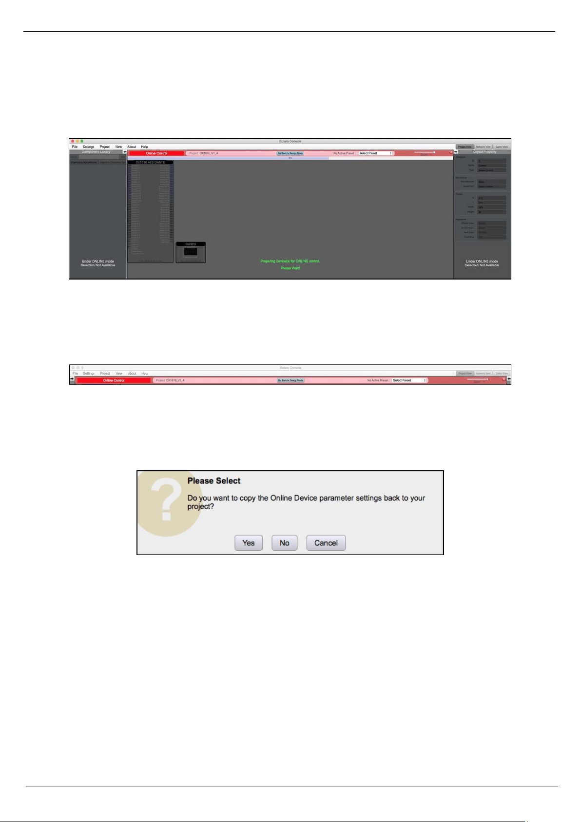
24
Note: At 90% the bar will stop und you might hear a mechanical clicking noise in DX1616. This is the relay,
which will mute all in- and outputs during the write process. The last 10% can take time to prepare the
DX1616 and its presets. After 100% the relay will unmute the system.
Figure 18: Preparing devices to online control message
Note that the Design Mode label at the top of the page has changed to red “Online Control” and that the
“Load Design to Device” button (now grey) has been re-named in “Go Back to Design Mode”.
Figure 19: “Go back to Design Mode” – switching to Offline
Switch back to Design Mode (Offline Mode)
Note: You can make parameter adjustments to the DX1616 while in Online Mode. When you do, upon
switching back to Design Mode you will be asked:
Figure 20: Copying settings to project file – yes ore not
“do you want to copy the Online Device parameter settings back to your project (file)” – “yes” or “no”.
So you can make all kinds of parameter adjustment changes to the DSP modules in Online Mode, hear their
effect live, and not affect the related DX1616 project file as saved on your PC if you select “No” from that
menu.
Or select “Yes” to modify your (personal) project file and continue working or “Yes” and “Save As”
immediately to save the changed processor settings to new project file.
Note: Remember to keep the origin RCF default project file *.pjxml as backup!
25
4.3 Solaro Control - Programming
After successful network connection of DX1616 including the host computer and a control device (host
computer, second computer or iPad/Android devices), this chapter explains the how setting up the Solaro
Control Interfaces.
Note: for save and comfortable operating, we recommend to use at least one host PC running the Solaro
Console software & Solaro Control Software. For some reasons also the addition of a remote computer (or
iPad) with Solaro Control running is useful.
The best performance and maximum control is reached by using both Solaro Console and Control software.
Even no remote computer is a must have, because you can run also the Solaro Control App on your host PC.
The Solaro Control GUI offers a 4:3 ratio fixed size remote panel (1024x720 px) which can be used on a PC,
Macbook or iPad in the same way.
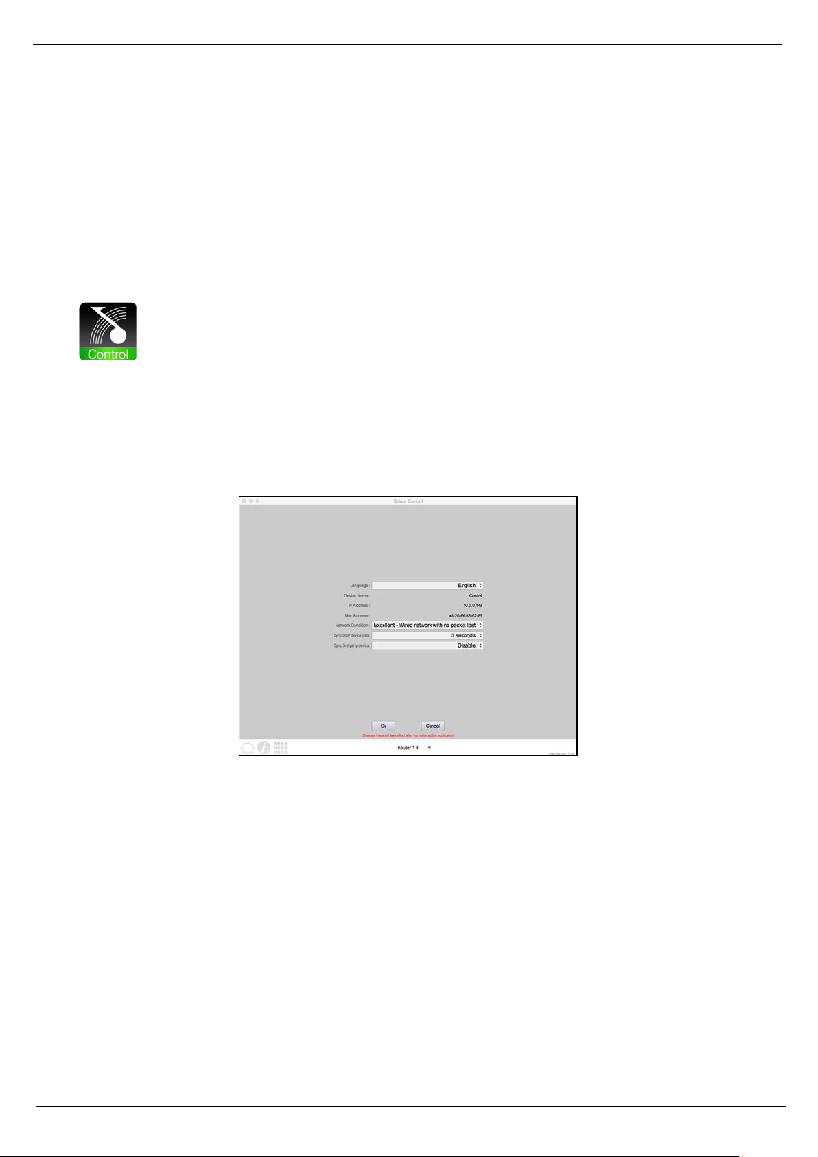
Solaro Control settings
Figure 21: Solaro Control settings
In the settings menu you can adjust:
• the language
• network condition to manage the bandwidth
• set timing to sync DSP device data (5 sec recommended)
• set timing to sync 3
rd
party devices (will be disabled by default)
In the settings, you can also read out the device name (by default “Control”), the IP Address and Mac Address
of the mapped device.
26
Now we can come back in the “Project View” and by doubleclick on the Solaro Control Icon we can access to
the first page of the controller. Which now is empty.
Figure 22: Solaro Control - empty workspace
Note: If you are working with the DX1616_V1_4 project file (associated with the RCF CR 16 ND), the Solaro
Control Interface is al already programmed. If you are working with the DX_1616_GP_1 project file, you will
need to program and customize the Solaro Control Interface in accord with your needs.
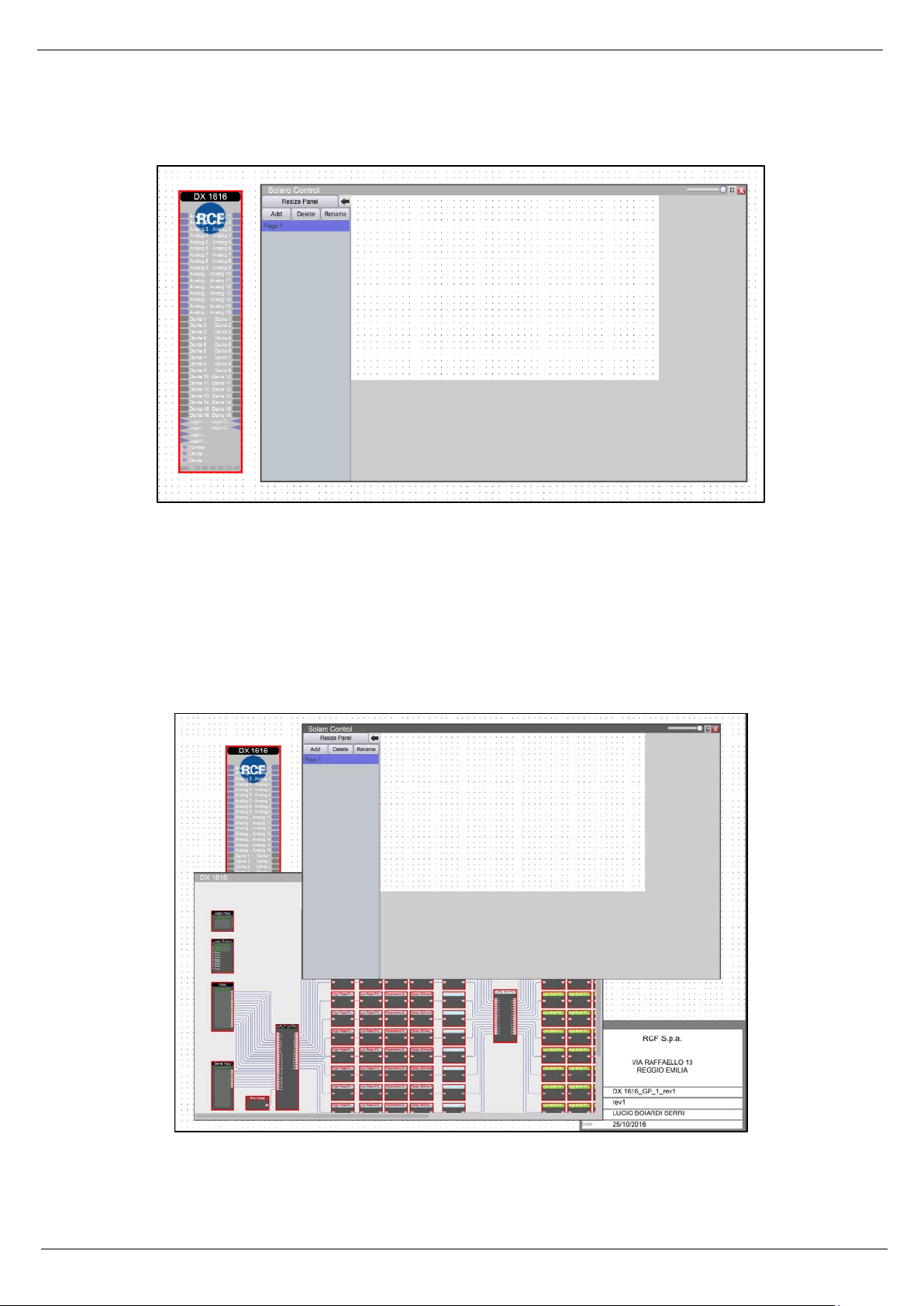
Now, by doubleclick on the DX 1616 Icon we can see all the modules of the project. (in this example the
DX_1616_GP_1 project file).
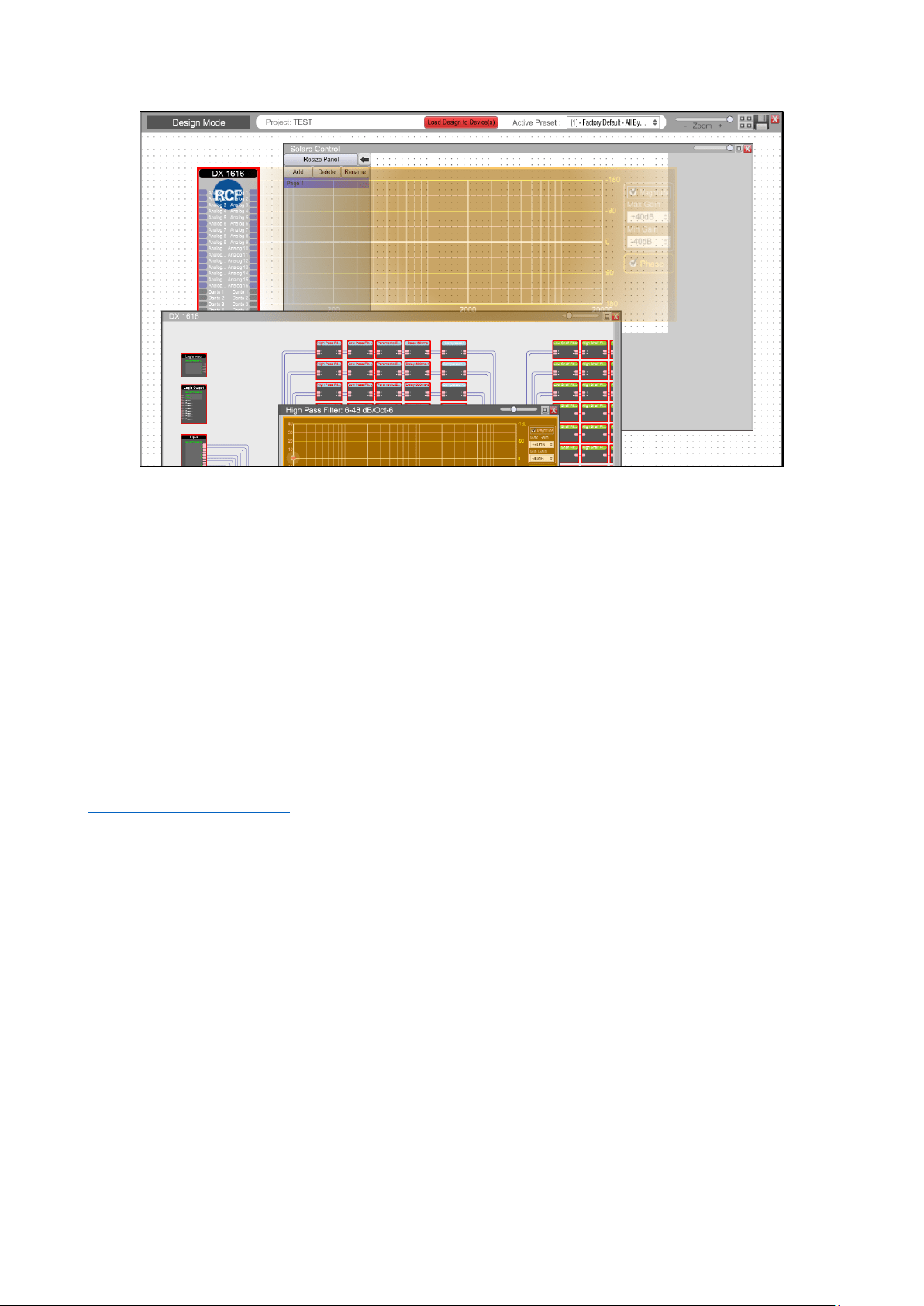
Now the DX 1616 contents and the Solaro Control Workspace are overlapped.
Figure 23: Solaro Control - DX1616 and Solaro Control Overlapped
27
Figure 24: Solaro Control - DX1616 and Solaro Control - Programming
Now you can doubleclick on a module of the DX 1616 content and drag on the Solaro Control Workspace the
parameters that you need to manage.
This approach is really smart because you can drag in the Solaro Control Interface only the parameters of the
DX 1616 that you really need to manage in your set up.
For Example you can set up a Solaro Control on a PC with all the parameters and another Solaro Control on
a small phone with only some parameters.
On the Solaro Control Workspace you have all the tools to manage and customize your Control Interfaces:
size of the buttons and graphics ,colors, positions etc.
For more details about Solaro Consolle and Control Interfaces you can refer to the xilica solaro help at
http://xilica.com/solarohelp/
.
28
4.3 Save and Creating Presets
In every Project you can save up to 70 different presets about all the modules of our project.
How can I safe my settings?
If you would like to safe the settings of your current DX1616 project, please proceed like this:
1. Switch back to Design Mode (Offline Mode). You will be asked, if your current settings shall be copied
from DX1616 to the project file.
2. Confirm with “Yes” and safe your project file “File>Safe as” on your computer.
3. Now you can create a preset of your parameters.
When you are Online, by switching back to Design Mode you will be asked:
Figure 25: Switching back to Design Mode – Copying parameters to project file
“do you want to copy the Online Device parameter settings back to your project (file)” – “yes” or “no”.
Select “Yes” to modify your (personal) project file and “Save As” immediately to save the changed processor
settings to new project file.
Note: Remember to keep the origin RCF default project file *.pjxml as backup!
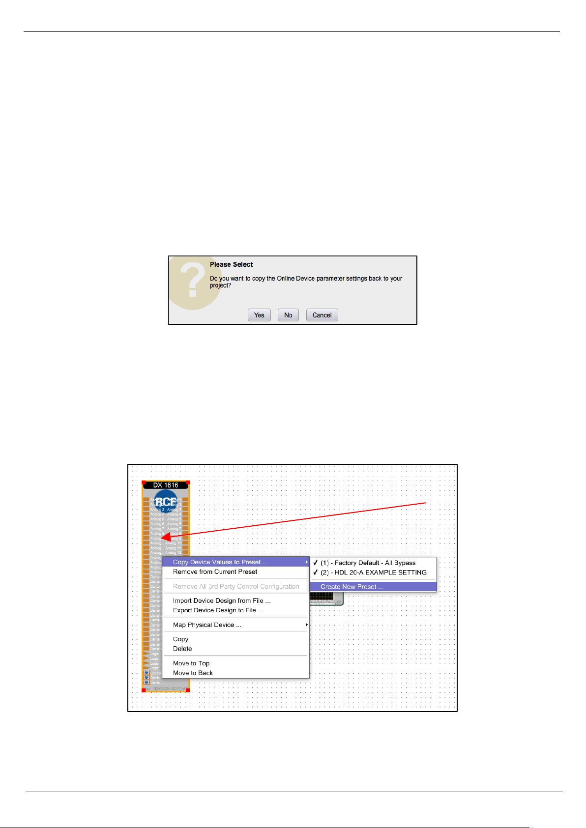
Right click the “DX 1616” icon in the project view and select “Save Module Value to Preset” > “Create New
Preset”
Figure 26: “Design Mode” – project view
29
The modules values will be saved in the selected preset. This can be just one module parameter (level, EQ,
Mute and so on) or even all currently set parameters. What ever you select will be saved.
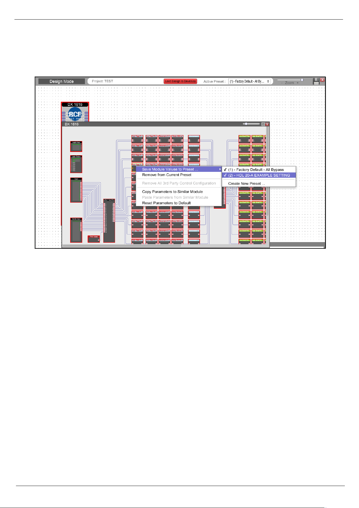
Figure 27: “Design Mode” – Save Module Values to Preset
After selection click the right mouse button and select “Save Module Value to Preset” > “Create New Preset”
Note: Be careful! You can overwrite existing presets (also the default RCF ones).
Close the DX1616 window and double click now the “Control” icon in the project view and maximize the
window if needed.
Select the new preset and drag it to the Solaro Control Worksace
Now you can edit the new created button. Adjust colors, font sizes and even text labels with the tools
available in “Object Property” on the right side of the screen

30
Now save the new project file “Save Project As”.
To transfer the new project file including your new preset you have click “Load Design To Device” like
descripted before. Now you have to commit with “Yes” in all windows.
How can I edit and save a preset?
You exactly start like shown in the chapter “Create preset”. Instead of selecting “Create New Preset”, just
select the one you would like to overwrite (edit).
RCF Engineering Support Group is at your disposal for any information and clarification you might require
techsupport.pro@rcf.it
.

31
5. Technical Data
Inputs and Outputs
Input Impedance: >10k Ohms (balanced)
Phantom Power 44V (open ciruit), 21V (loaded circuit)
Output Impedance: < 120 Ohms
Maximum Level: +20dBu (Mic Gain 0dB/ +40dB steps)
Type: Electronically balanced
Audio Performance
Frequency Response: +/- 0.1dB (20Hz to 22 kHz)
Dynamic Range: 110dB typ (unweigthed)
CMMR: > 100dB (50 to 10kHz)
Crosstalk: < -100dB
Distortion THD+N: < 0.001% (1 kHz @ -1dBFS)
Digital Audio Performance
Processor: 40-bit floating point
Input SRC range AES/EBU: 16kHz – 96kHz with switchable Independent SRCs
Analog Converters: High Performance 24 bit
Propagation delay: 3.2ms (Analog in to analog out), 4.2ms (AES/EBU to analog out)
Output Sampling Rate: 48 kHz
Dante Sampling Rate: 48 kHz
Encoding: PCM32
Front Panel Control
Signal LEDs: 1 per input and output channel (multi color LED)
Status LEDs: Power and network (data)
Connectors
Analog I/O: Phoenix 3.5mm (included)
Digital I/O: DB25 (AES/EBU) Tascam compartible format
Logic In-Relay Out: Phoenix 3.5mm (included)
TCP/IP: RJ45
Network Audio I/O: RJ45 for Dante A, Dante B
General
Power socket: Standard IEC socket, VDE
Power: 90-240VAC 50-60Hz
Dimensions: 483 x 44 x 229mm (19“, 1 RU)
Rack Mount: 1 RU vent between units
Weight: 5kg

10307589 Rev A
www.rcf.it
RCF S.p.A.
Via Raffaello Sanzio, 13
42124 Reggio Emilia - Italy
Tel +39 0522 274 411
Fax +39 0522 232 428
e-mail: info@rcf.it