
Operator's
Manual
Since it began making garden tools in
1850,Bolens has been known for long-
lasting, dependable products. Bolens
eventually carried that hard-working
heritage into the outdoor power
equipment industry, when it designed
and built the first-ever power-driven
garden tractor.
Today,homeowners around the country rely
on Bolens for durable, reliable power
equipment at an affordable price.
2-Cycle Petrol
Trimmer/Brushcutter
ModelBL250
INTRODUCTION
THANKYOU
Thank you for buying this quality product. This modern
outdoor power tool will provide many hours of useful service.
You will find it to be a great labor-saving device. This
operator's manual provides you with easy-to-understand
operating instructions. Read the whole manual and follow all
the instructions to keep your new outdoor power tool in top
operating condition.
PRODUCT REFERENCES, ILLUSTRATIONS AND
SPECIFICATIONS
All information, illustrations, and specifications in this manual
are based on the latest product information available at the
time of printing. We reserve the right to make changes at any
time without notice.
Bump Head TMis a trademark of MTD SOUTHWEST INC.
SplitLine TMis a trademark of MTD SOUTHWEST INC.
Copyright 02003 MTD SOUTHWEST INC, All Rights Reserved.
SERVICE INFORMATION
Service on this unit both within and after the warranty period
should be performed only by an authorized and approved
service dealer.
DO NOT RETURN THE UNITTO THE RETAILER. PROOF OF
PURCHASE WILL BE REQUIRED FOR WARRANTY SERVICE.
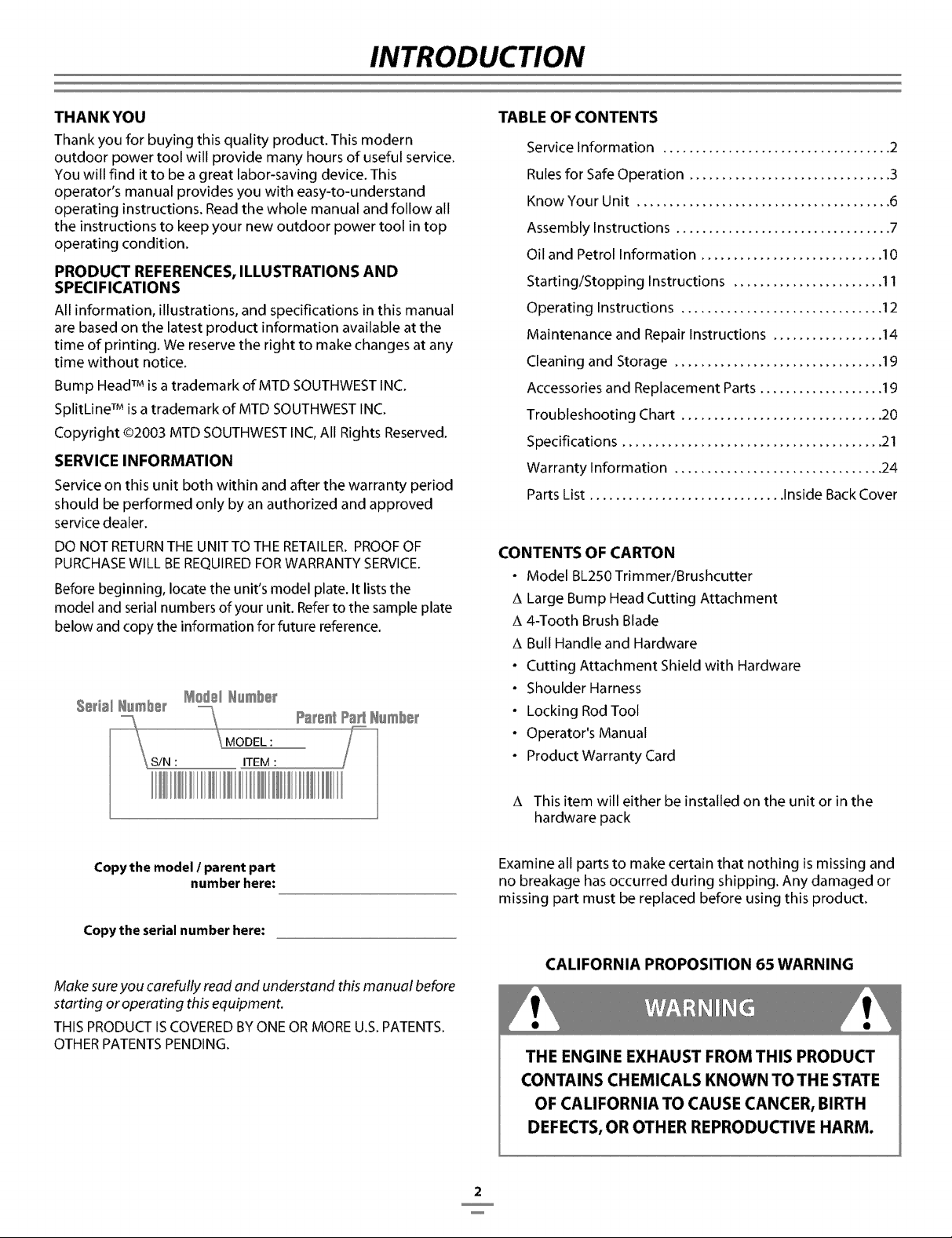
Before beginning, locate the unit's model plate. It lists the
model and serial numbers of your unit. Refer to the sample plate
below and copy the information for future reference.
TABLE OF CONTENTS
Service Information ................................... 2
Rules for Safe Operation ............................... 3
Know Your Unit ....................................... 6
Assembly Instructions ................................. 7
Oil and Petrol Information ............................ I0
Starting/Stopping Instructions ....................... 11
Operating Instructions ............................... 12
Maintenance and Repair Instructions ................. 14
Cleaning and Storage ................................ 19
Accessories and Replacement Parts ................... 19
Troubleshooting Chart ............................... 20
Specifications ........................................ 21
Warranty Information ................................ 24
Parts List .............................. Inside Back Cover
CONTENTS OF CARTON
• Model BL250Trimmer/Brushcutter
A Large Bump Head Cutting Attachment
A 4-Tooth Brush Blade
A Bull Handle and Hardware
• Cutting Attachment Shield with Hardware
• Shoulder Harness
• Locking Rod Tool
• Operator's Manual
• Product Warranty Card
A This item will either be installed on the unit or in the
hardware pack
Copy the model I parent part
number here:
Copy the serial number here:
Make sureyou carefully read and understand this manual before
starting or operating this equipment.
THISPRODUCTISCOVEREDBYONE ORMOREU.S.PATENTS.
OTHERPATENTSPENDING.
Examine all parts to make certain that nothing is missing and
no breakage has occurred during shipping. Any damaged or
missing part must be replaced before using this product.
CALIFORNIA PROPOSITION 65 WARNING
THE ENGINE EXHAUST FROM THIS PRODUCT
CONTAINS CHEMICALS KNOWN TO THE STATE
OF CALIFORNIA TO CAUSE CANCER, BIRTH
DEFECTS, OR OTHER REPRODUCTIVE HARM.
2
RULES FOR SAFE OPERATION
NOTE: For users on U.S. Forest Land and in the states of California, Maine, Oregon, and Washington. All U.S. Forest Land and
the state of California (Public Resources Codes 4442 and 4443), Oregon, and Washington require by law that certain internal com-
bustion engines operated on forest brush and/or grass-covered areas be equipped with a spark arrestor, maintained in effective
working order, or the engine be constructed, equipped, and maintained for the prevention of fire. Check with your state or local
authorities for regulations pertaining to these requirements. Failure to follow these requirements could subject you to liability or a
fine. This unit is factory equipped with a spark arrestor. If it requires replacement, ask your LOCAL SERVICE DEALER to install
the Accessory Part #182747 Spark Arrestor.
Read the Operator's Manual(s) and follow all warnings and safety instructions.
Failure to do so can result in serious injury to the operator and/or bystanders.
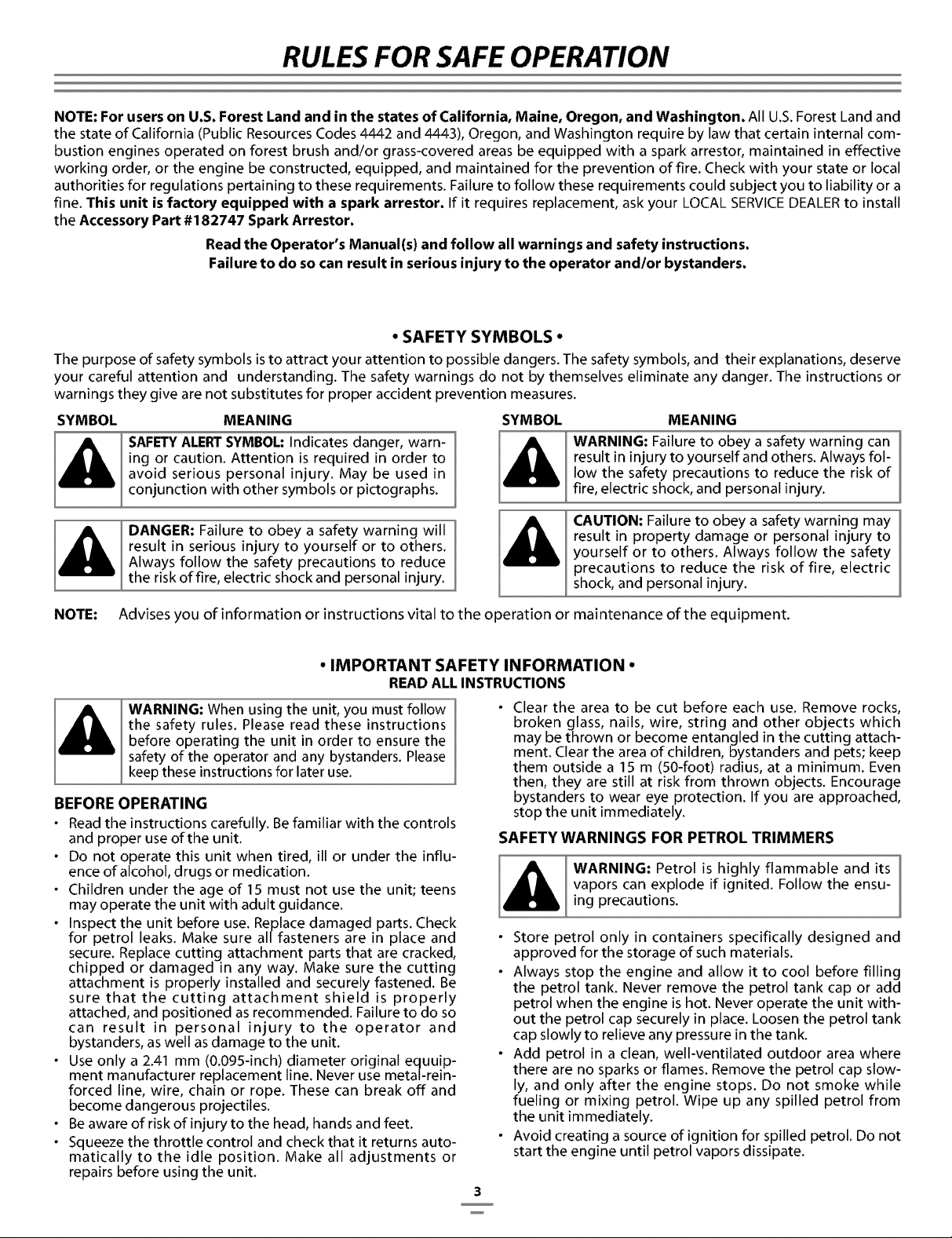
° SAFETY SYMBOLS •
The purpose of safety symbols is to attract your attention to possible dangers. The safety symbols, and their explanations, deserve
your careful attention and understanding. The safety warnings do not by themselves eliminate any danger. The instructions or
warnings they give are not substitutes for proper accident prevention measures.
SYMBOL MEANING
SAFETY ALERT SYMBOL: Indicates danger, warn-
ing or caution. Attention is required in order to
avoid serious personal injury. May be used in
conjunction with other symbols or pictographs.
DANGER: Failure to obey a safety warning will
result in serious injury to yourself or to others.
Always follow the safety precautions to reduce
the risk of fire, electric shock and personal injury.
SYMBOL MEANING
WARNING: Failure to obey a safety warning can
result in injury to yourself and others. Always fol-
low the safety precautions to reduce the risk of
fire, electric shock, and personal injury.
CAUTION: Failure to obey a safety warning may
result in property damage or personal injury to
yourself or to others. Always follow the safety
precautions to reduce the risk of fire, electric
shock, and personal injury.
NOTE: Advises you of information or instructions vital to the operation or maintenance of the equipment.
° IMPORTANT SAFETY INFORMATION •
READ ALL INSTRUCTIONS
WARNING: When using the unit, you must follow
the safety rules. Please read these instructions
before operating the unit in order to ensure the
safety of the operator and any bystanders. Please
keep these instructions for later use.
BEFORE OPERATING
• Read the instructions carefully. Be familiar with the controls
and proper use of the unit.
• Do not operate this unit when tired, ill or under the influ-
ence of alcohol, drugs or medication.
• Children under the age of 15 must not use the unit; teens
may operate the unit with adult guidance.
• Inspect the unit before use. Replace damaged parts. Check
for petrol leaks. Make sure all fasteners are in place and
secure. Replace cutting attachment parts that are cracked,
chipped or damaged in any way. Make sure the cutting
attachment is properly installed and securely fastened. Be
sure that the cutting attachment shield is properly
attached, and positioned as recommended. Failure to do so
can result in personal injury to the operator and
bystanders, as well as damage to the unit.
• Use only a 2.41 mm (O.095-inch) diameter original equuip-
ment manufacturer replacement line. Never use metal-rein-
forced line, wire, chain or rope. These can break off and
become dangerous projectiles.
• Be aware of risk of injury to the head, hands and feet.
• Squeeze the throttle control and check that it returns auto-
matically to the idle position. Make all adjustments or
repairs before using the unit.
Clear the area to be cut before each use. Remove rocks,
broken glass, nails, wire, string and other objects which
may be thrown or become entangled in the cutting attach-
ment. Clear the area of children, bystanders and pets; keep
them outside a 15 m (50-foot) radius, at a minimum. Even
then, they are still at risk from thrown objects. Encourage
bystanders to wear eye protection. If you are approached,
stop the unit immediately.
SAFETY WARNINGS FOR PETROL TRIMMERS
WARNING: Petrol is highly flammable and its
vapors can explode if ignited. Follow the ensu-
ing precautions.
• Store petrol only in containers specifically designed and
approved for the storage of such materials.
• Always stop the engine and allow it to cool before filling
the petrol tank. Never remove the petrol tank cap or add
petrol when the engine is hot. Never operate the unit with-
out the petrol cap securely in place. Loosen the petrol tank
cap slowly to relieve any pressure in the tank.
• Add petrol in a clean, well-ventilated outdoor area where
there are no sparks or flames. Remove the petrol cap slow-
ly, and only after the engine stops. Do not smoke while
fueling or mixing petrol. Wipe up any spilled petrol from
the unit immediately.
• Avoid creating a source of ignition for spilled petrol. Do not
start the engine until petrol vapors dissipate.
3

RULES FOR SAFE OPERATION
° IMPORTANT SAFETY INFORMATION •
Move the unit at least 9.1 m (30 feet) from the fueling
source and site before starting the engine. Do not smoke.
Keep sparks and open flames away from the area while
adding petrol or operating the unit.
WHILE OPERATING
• Never start or run the unit inside a closed room or building.
Breathing exhaust fumes can be fatal. Operate this unit
only in a well-ventilated outdoor area.
• Wear safety glasses or goggles that meet ANSI Z87.1 stan-
dards and are marked as such. Wear ear/hearing protection
when operating this unit. Wear a face or dust mask if the
operation is dusty.
• Wear heavy long pants, boots, gloves and a long sleeve
shirt. Do not wear loose clothing, jewelry, short pants, san-
dals or go barefoot. Secure hair above shoulder level.
• The cutting attachment shield must always be in place while
operating the unit. Do not operate unit without both trim-
ming lines extended, and the proper line installed. Do not
extend the trimming line beyond the length of the shield.
• This unit has a clutch. The cutting attachment remains sta-
tionary when the engine is idling. If it does not, have the
unit adjusted by an authorized service technician.
• Adjust the handle to your size in order to provide the best
grip.
• Be sure the cutting attachment is not in contact with any-
thing before starting the unit.
• Use the unit only in daylight or good artificial light.
• Avoid accidental starting. Be in the starting position when-
ever pulling the starter rope. Both the operator and unit
must be in a stable position while starting. Refer to the
Starting/Stopping Instructions.
• Use the right tool. Only use this tool for its intended purpose.
• Do not overreach. Always keep proper footing and balance.
• Always hold the unit with both hands when operating.
Keep a firm grip on both handles or grips.
• Keep hands, face, and feet at a distance from all moving
parts. Do not touch or try to stop the cutting attachment
when it rotates.
• Do not touch the engine, gear housing or muffler. These
parts get extremely hot from operation, even after the unit
is turned off.
• Do not operate the engine faster than the speed needed to
cut, trim or edge. Do not run the engine at high speed
when not cutting.
• Always stop the engine when cutting is delayed or when
walking from one cutting location to another.
• If you strike or become entangled with a foreign object,
stop the engine immediately and check for damage. Do
not operate before repairing damage. Do not operate the
unit with loose or damaged parts.
• Stop the unit, switch the engine to off, and disconnect the
spark plug for maintenance or repair.
• Use only original equipment manufacturer replacement
parts and accessories for this unit. These are available from
your authorized service dealer. Use of any non-original fac-
tory parts or accessories could lead to serious injury to the
user, or damage to the unit, and void your warranty.
• Keep unit clean of vegetation and other materials. They may
become lodged between the cutting attachment and shield.
• To reduce fire hazard, replace a faulty muffler and spark
arrestor. Keep the engine and muffler free from grass,
leaves, excessive grease or carbon build up.
WHILE OPERATING WITH CUTTING BLADE
• Read and understand all safety warnings before operating
this unit.
• Always use the shoulder harness when using the brush
blade accessory.
• Keep the handle between the operator and cutting attach-
ment or blade at all times.
• NEVER cut when the cutting blade is 76 cm (30 inches) or
more above the ground level.
• Blade thrust may occur when the spinning blade contacts
an object that it does not immediately cut. Blade thrust can
be violent enough to propel the unit and/or operator in
any direction, possibly causing a loss of control. Blade
thrust can occur without warning if the blade snags, stalls
or binds. This is more likely to occur in areas where it is dif-
ficult to see the material being cut.
• For operation with the brush blade, do not cut anything thick-
er than 13 mm (1/2 inch) or a violent kickback could occur.
• Do not attempt to touch or stop the blade when it is rotating.
• A coasting blade can cause injury while it continues to spin
after the engine is stopped or the throttle trigger is
released. Maintain proper control until the blade has com-
pletely stopped rotating.
• Do not run the unit at high speed when not cutting.
• If you strike or become entangled with a foreign object, stop
the engine immediately and check for damage. Have any
damage repaired before attempting further operations. Do
not operate unit with a bent, cracked or dull blade. Discard
blades that are bent, warped, cracked or broken.
• Do not sharpen the cutting blade. Sharpening the blade
can cause the blade tip to break off while in use. This can
result in severe personal injury. Replace the blade.
• Do not use the cutting blade for edging or as an edger; severe
personal injury to yourself or others may incur. Use the cutting
blade only for the purpose as described in this manual.
• Stop the engine IMMEDIATELY if you feel excessive vibra-
tion. Vibration is a sign of trouble. Inspect thoroughly for
loose nuts, bolts or damage before continuing. Repair or
replace affected parts as necessary.
After Use
• Clean cutting blades with a household cleaner to remove any
gum buildup. Oil the blade with machine oil to prevent rust.
• Lock up and store the cutting blade in an appropriate area
to protect the blade from unauthorized use or damage.
OTHER SAFETY WARNINGS
• Never store a fueled unit inside a building where fumes
may reach an open flame or spark.
• Allow the engine to cool before storing or transporting. Be
sure to secure the unit while transporting.
• Store the unit in a dry area, locked up or up high to prevent
unauthorized use or damage, out of the reach of children.
• Never douse or squirt the unit with water or any other liq-
uid. Keep handles dry, clean and free from debris. Clean
after each use, see Cleaning and Storage instructions.
• Keep these instructions. Refer to them often and use them
to instruct other users. If you loan someone this unit, also
loan them these instructions.
SAVE THESE INSTRUCTIONS
4

RULES FOR SAFE OPERATION
SAFETY AND INTERNATIONAL SYMBOLS
Thisoperator's manual describes safety and international symbols and pictographs that may appear on this product.
Readthe operator's manual for complete safety, assembly, operating and maintenance and repair information.
SYMBOL MEANING SYMBOL MEANING
SAFETY ALERT SYMBOL
Indicates danger, warning or caution.
May be used in conjunction with other
symbols or pictographs.
WARNING - READ OPERATOR'S
MANUAL
Read the operator's manual(s) and follow
all warnings and safety instructions.
Failure to do so can result in serious
injury to the operator and/or bystanders.
WEAR EYE AND HEARING
PROTECTION
WARNING: Thrown objects and loud
noise can cause severe eye injury and
hearing loss. Wear eye protection
meeting ANSI Z87.1 standards and ear
protection when operating this unit. Use
a full face shield when needed.
KEEP BYSTANDERS AWAY
WARNING: Keep all bystanders,
especially children and pets, at least 15 m
(50 feet) from the operating area.
• UNLEADED PETROL
Always use clean, fresh unleaded petrol.
A B
THROWN OBJECTS AND ROTATING
CUTTER CAN CAUSE SEVERE
INJURY
WARNING: Do not operate without the
cutting attachment shield in place.
Keep away from the rotating cutting
attachment.
HOT SURFACE WARNING
Do not touch a hot muffler, gear housing
or cylinder. You may get burned. These
parts get extremely hot from operation.
They remain hot for a short time after the
unit is turned off.
SHARP BLADE
WARNING: Sharp blade on cutting
attachment shield. To prevent serious
injury, do not touch line cutting blade.
c
• CHOKE CONTROL
A • FULL choke position
B • PARTIAL choke position
C • RUN position
BRUSHCUTTERS • REPLACE DULL
BLADES
Do not sharpen the cutting blade.
Sharpening the blade can cause the
blade tip to break off while in use. This
can result in severe personal injury.
I
0
• OIL
Refer to operator's manual for the proper
type of oil.
° ON/OFF STOP CONTROL
ON / START/RUN
• ON/OFF STOP CONTROL
OFFor STOP
@
TRIMMER/BRUSHCUTTER SAFETY
WARNING: Thrown objects and rotating
cutter can cause severe injury. Keep
bystanders, especially children and pets,
at least 15 m (50 feet) away from the
cutting area. The cutting attachment
shield must be used when using the
trimmer cutting attachment.
5
RULES FOR SAFE OPERATION
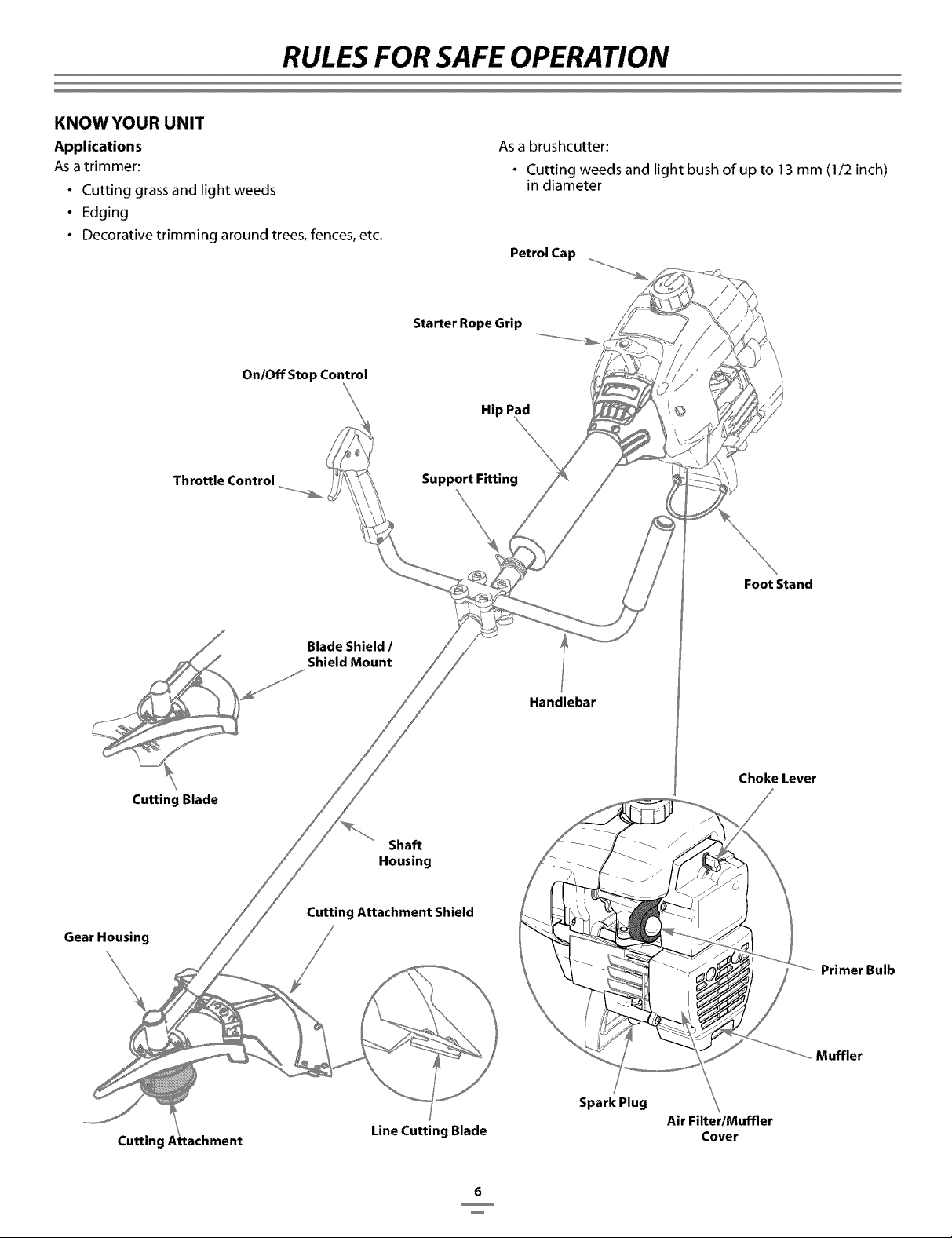
KNOW YOUR UNIT
Applications
As a trimmer:
• Cutting grass and light weeds
• Edging
• Decorative trimming around trees, fences, etc.
As a brushcutter:
• Cutting weeds and light bush of up to 13 mm (I/2 inch)
in diameter
Petrol Cap
On/Off Stop Control
Starter Rope Grip
Hip Pad
Throttle Control Support Fitting
Foot Stand
Blade Shield 1
Shield Mount
Handlebar
Cutting Blade
Gear Housing
Cutting
Shaft
Housing
Cutting Attachment Shield
Line Cutting Blade
Spark Plug
Choke Lever
Air Filter/Muffler
Cover
Primer Bulb
Muffler
6

ASSEMBLY INSTRUCTIONS
INSTALL AND ADJUST THE HANDLE
1. Place the handlebar between the top and middle clamp
pieces (Fig. 1).
...........(4) Screws ........... Fig. 1
Middle Clam
.............N '_
uts Clamp
2. While holding the three pieces together, install the four (4)
screws through the top clamp and into middle clamp.
NOTE: The holes in the top and middle clamp will line
up only when assembled correctly.
3. Place the clamps and the handlebar over the shaft
housing and onto the bottom clamp.
4. Hold each hex nut in the bottom clamp recess with a
finger. Start screws with a large Phillips screwdriver. Do
not tighten until you make the handle adjustment.
5. While holding the unit in the operating position (Fig. 2),
move the handlebar to the location that provides you the
best g rip.
Fig. 2
6. Tighten the clamp screws evenly, until the handlebar is
secu re.
INSTALL THE HARNESS
WARNING: Always use the shoulder harness
when using the cutting blade to avoid serious
personal injury.
1. Push the strap through the center of the buckle.
2. Pull the strap over the cross bar and clown through the
slot in the buckle (Fig. 3).
3. Put the harness on over your head and onto your
shoulder. Snap it on to the support fitting (Fig. 4).
4. Adjust the length to fit the operator's size. Pull the tab to
lengthen, pull the strap to shorten (Fig 5).
fz .• ••••••
I Fig. 3
I Fig. 4
Support Fitting
Fig. 5
/
/
REMOVE AND INSTALL THE CUTTING SHIELD
Remove the cutting attachment shield when using the
unit as a brushcutter
WARNING: The cutting attachment shield must
NOT be installed when operating the unit with a
blade. Remove the cutting attachment shield
before removing or installing the blade.
Remove the cutting attachment shield from the shield
mount by removing the three (3) screws with a flat blade
screwdriver (Fig. 7). Store parts for future use.
7
ASSEMBLY INSTRUCTIONS
Cutting
Attachment
Shield
(3) Screws
Fig.6
Gear Housing
Shield Mount
Install the cutting attachment shield when using the unit
as a grass trimmer
WARNING: To avoid serious personal injury, the
cutting attachment shield MUST be in place at all
times while operating the unit as a grass trimmer.
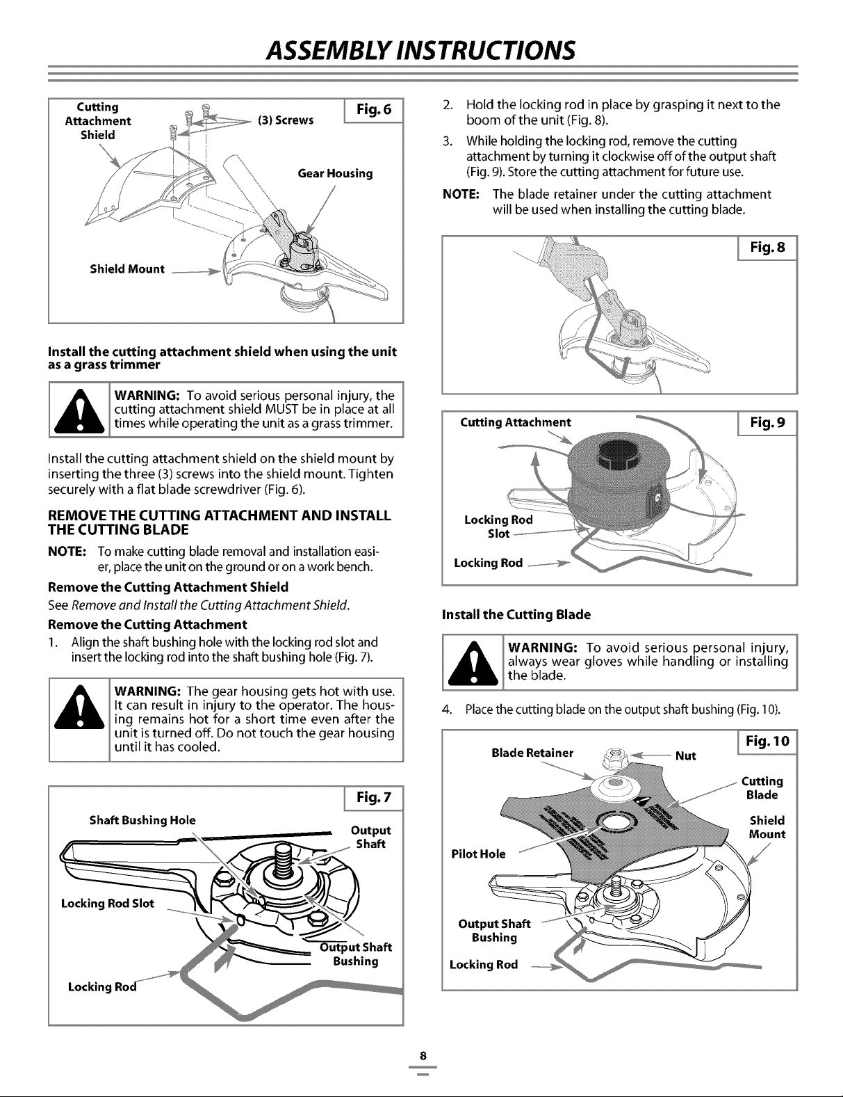
Install the cutting attachment shield on the shield mount by
inserting the three (3) screws into the shield mount. Tighten
securely with a flat blade screwdriver (Fig. 6).
REMOVE THE CUTTING ATTACHMENT AND INSTALL
THE CUTTING BLADE
NOTE: To make cutting blade removal and installation easi-
er, place the unit on the ground or on a work bench.
Remove the Cutting Attachment Shield
See Remove and Install the Cutting Attachment Shield.
Remove the Cutting Attachment
I. Align the shaft bushing hole with the locking rod slot and
insert the locking rod into the shaft bushing hole (Fig. 7).
WARNING: The gear housing gets hot with use.
It can result in injury to the operator. The hous-
ing remains hot for a short time even after the
unit is turned off. Do not touch the gear housing
until it has cooled.
Shaft Bushing Hole
Locking Rod Slot
Locking
Fig. 7
Output
Shaft
Output Shaft
Bushing
2. Hold the locking rod in place by grasping it next to the
boom of the unit (Fig. 8).
3. While holding the locking rod, remove the cutting
attachment by turning it clockwise offofthe output shaft
(Fig. 9). Store the cutting attachment for future use.
NOTE: The blade retainer under the cutting attachment
will be used when installing the cutting blade.
I Fig. 8
Cutting Attachment Fig. 9
Locking Rod
Slot
Locking Rod
Install the Cutting Blade
always wear gloves while handling or installing
the blade.
4. Place the cutting blade on the output shaft bushing (Fig. 10).
Fig. 10
Blade Retainer _ Nut
Pilot Hole
Cutting
Blade
Shield
Mount
Output Shaft
Bushing
Locking Rod
8
ASSEMBLY INSTRUCTIONS
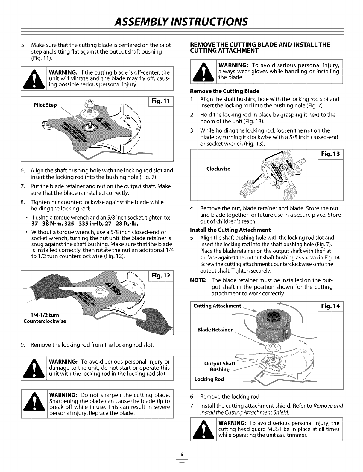
5.
Make sure that the cutting blade is centered on the pilot
step and sitting flat against the output shaft bushing
(Fig. 11 ).
WARNING: If the cutting blade is off-center, the /
unit will vibrate and the blade may fly off, caus-
ing possible serious personal injury.
Pilot Step
I Fig. 11
.
7.
8.
Align the shaft bushing hole with the locking rod slot and
insert the locking rod into the bushing hole (Fig. 7).
Put the blade retainer and nut on the output shaft. Make
sure that the blade is installed correctly.
Tighten nut counterclockwise against the blade while
holding the locking rod:
If using a torque wrench and an 5/8 inch socket, tighten to:
37 - 38 N-m, 325 - 335 in-lb, 27 - 28 ft.-lb.
Without a torque wrench, use a 5/8 inch closed-end or
socket wrench, turning the nut until the blade retainer is
snug against the shaft bushing. Make sure that the blade
is installed correctly, then rotate the nut an additional 1/4
to 1/2 turn counterclockwise (Fig. 12).
I Fig. 12
114-112 turn
Counterclockwise
9. Remove the locking rod from the locking rod slot.
_ WARNING: To avoid serious personal injury or
damage to the unit, do not start or operate this
unit with the locking rod in the locking rod slot.
WARNING: Do not sharpen the cutting blade.
Sharpening the blade can cause the blade tip to
break off while in use. This can result in severe
personal injury. Replace the blade.
REMOVE THE CUTTING BLADE AND INSTALL THE
CUTTING ATTACHMENT
WARNING: To avoid serious personal injury,
always wear gloves while handling or installing
the blade.
Remove the Cutting Blade
1. Align the shaft bushing hole with the locking rod slot and
insert the locking rod into the bushing hole (Fig. 7).
2. Hold the locking rod in place by grasping it next to the
boom of the unit (Fig. 13).
3. While holding the locking rod, loosen the nut on the
blade by turning it clockwise with a 5/8 inch closed-end
or socket wrench (Fig. 13).
Fig. 13
Clockwise
4. Remove the nut, blade retainer and blade. Store the nut
and blade together for future use in a secure place. Store
out of children's reach.
Install the Cutting Attachment
5. Align the shaft bushing hole with the locking rod slot and
insert the locking rod into the shaft bushing hole (Fig. 7).
Place the blade retainer on the output shaft with the flat
surface against the output shaft bushing as shown in Fig. 14.
Screw the cutting attachment counterclockwise onto the
output shaft. Tighten securely.
NOTE: The blade retainer must be installed on the out-
put shaft in the position shown for the cutting
attachment to work correctly.
Blade Retainer
Output Shaft
Bushing
Locking Rod
6. Remove the locking rod.
7. Install the cutting attachment shield. Refer to Remove and
Install the Cutting Attachment Shield.
WARNING: To avoid serious personal injury, the
cutting head guard MUST be in place at all times
while operating the unit as a trimmer.
9
OIL & PETROL INFORMATION
OIL AND FUEL MIXING INSTRUCTIONS
Old and/or improperly mixed fuel are the main reasons for
improper unit performance. Be sure to use fresh, clean
unleaded fuel. Follow the instructions carefully for the proper
fuel/oil mixture.
Definition of Blended Fuels
Today's fuels are often a blend of petrol and oxygenates such
as ethanol, methanol, or MTBE (ether). Alcohol-blended fuel
absorbs water. As little as 1% water in the fuel can make fuel
and oil separate. It forms acids when stored. When using
alcohol-blended fuel, use fresh fuel (less than 60 days old).
Using Blended Fuels
If you choose to use a blended fuel, or its use is unavoidable,
follow recommended precautions:
• Always use the fresh fuel mix explained in your opera-
tor's manual
• Always agitate the fuel mix before fueling the unit
• Drain the tank and run the engine dry before storing the
unit
Using Fuel Additives
The bottle of 2-cycle oil that came with your unit contains a
fuel additive which will help inhibit corrosion and minimize
the formation of gum deposits. It is recommended that you
use our 2-cycle oil with this unit.
If unavailable, use a good 2-cycle oil designed for air-cooled
engines along with a petrol additive, such as STA-BIL_ Petrol
Stabilizer or an equivalent. Add 23 ml (0.8 oz) of petrol
additive per gallon of petrol according to the instructions on
the container. NEVER add petrol additives directly to the
unit's petrol tank.
CAUTION: For proper engine operation and max-
imum reliability, pay strict attention to the oil and
petrol mixing instructions on the 2-cycle oil con-
tainer. Using improperly mixed petrol can severe-
ly damage the engine.
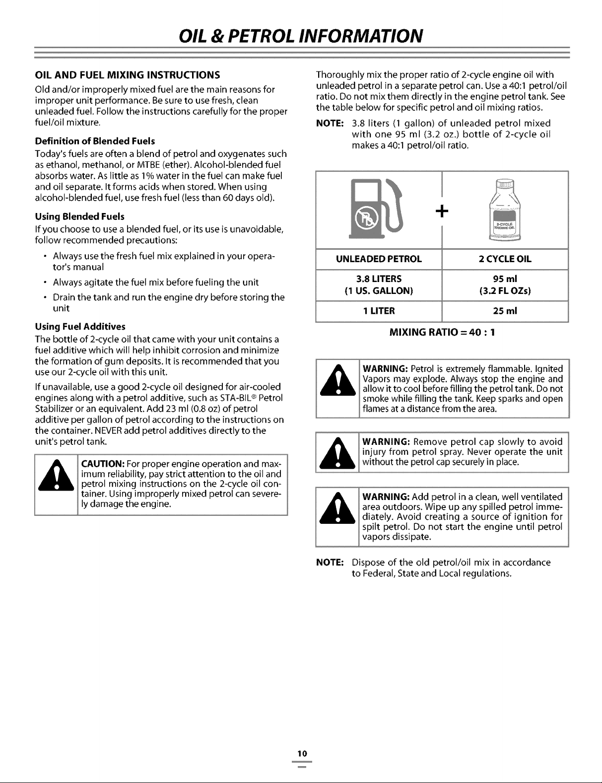
Thoroughly mix the proper ratio of 2-cycle engine oil with
unleaded petrol in a separate petrol can. Use a 40:1 petrol/oil
ratio. Do not mix them directly in the engine petrol tank. See
the table below for specific petrol and oil mixing ratios.
NOTE: 3.8 liters (1 gallon) of unleaded petrol mixed
with one 95 ml (3.2 oz.) bottle of 2-cycle oil
makes a 40:1 petrol/oil ratio.
UNLEADED PETROL 2 CYCLE OIL
3.8 LITERS 95 ml
(1 US. GALLON) (3.2 FL OZs)
1 LITER 25 ml
MIXING RATIO = 40 : 1
WARNING: Petrol is extremely flammable. Ignited
Vapors may explode. Always stop the engine and
allow it to cool before filling the petrol tank. Do not
smoke while filling the tank. Keep sparks and open
flames at a distance from the area.
WARNING: Remove petrol cap slowly to avoid
injury from petrol spray. Never operate the unit
without the petrol cap securely in place.
NOTE:
WARNING: Add petrol in a clean, well ventilated
area outdoors. Wipe up any spilled petrol imme-
diately. Avoid creating a source of ignition for
spilt petrol. Do not start the engine until petrol
vapors dissipate.
Dispose of the old petrol/oil mix in accordance
to Federal, State and Local regulations.
10
STARTING/STOPPING INSTRUCTIONS
[A
_, WARNING: Avoid accidental starting• Make sure you
are in the starting position when pulling the starter
rope (Fig• 17). To avoid serious injury, both the operator
and unit must be in a stable position while starting.
STARTING INSTRUCTIONS
1 •
2•
4•
5•
Mix petrol with oil• Fill petrol tank with petrol/oil mixture•
See 0ii and Petrol Mixing Instructions.
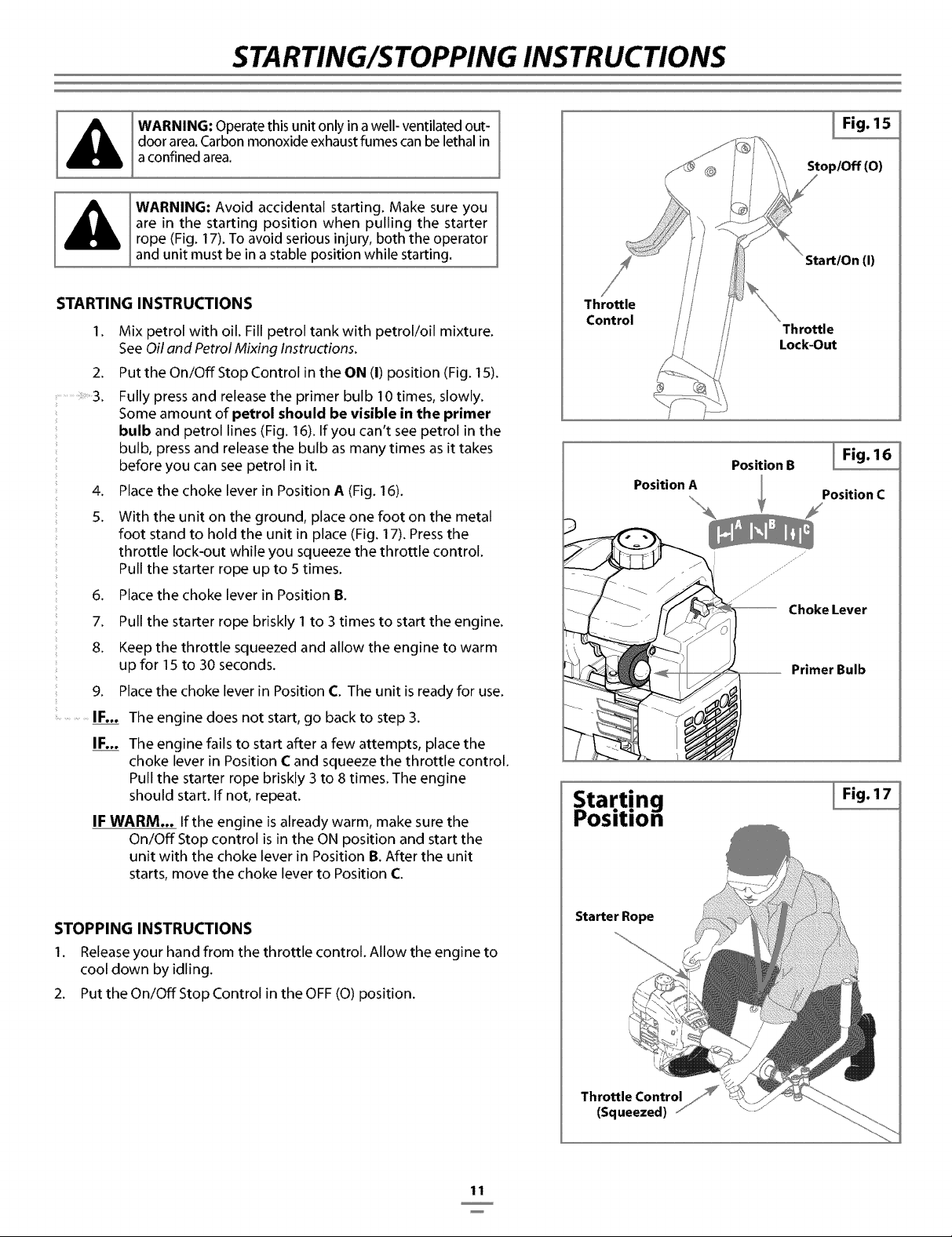
Put the On/Off Stop Control in the ON (I) position (Fig. 15).
Fully press and release the primer bulb I0 times, slowly.
Some amount of petrol should be visible in the primer
bulb and petrol lines (Fig. 16). If you can't see petrol in the
bulb, press and release the bulb as many times as it takes
before you can see petrol in it•
Place the choke lever in Position A (Fig. 16).
With the unit on the ground, place one foot on the metal
foot stand to hold the unit in place (Fig. 17)• Press the
throttle lock-out while you squeeze the throttle control.
Pull the starter rope up to 5 times.
6• Place the choke lever in Position B•
7• Pull the starter rope briskly I to 3 times to start the engine.
8• Keep the throttle squeezed and allow the engine to warm
up for 15 to 30 seconds.
9. Place the choke lever in Position C. The unit is ready for use•
.............IF... The engine does not start, go back to step 3•
IF... The engine fails to start after a few attempts, place the
choke lever in Position C and squeeze the throttle control.
Pull the starter rope briskly 3 to 8 times. The engine
should start• If not, repeat.
IF WARM... If the engine is already warm, make sure the
On/Off Stop control is in the ON position and start the
unit with the choke lever in Position B. After the unit
starts, move the choke lever to Position C
STOPPING INSTRUCTIONS
I• Release your hand from the throttle control. Allow the engine to
cool down by idling.
2. Put the On/Off Stop Control in the OFF (O) position.
Throttle
Control
Position A
Starting
osidon
Starter Rope
I Fig. 15
Stop/Off (O)
Start/On (I)
Throttle
Lock-Out
Position B
I Fig. 16
Position C
Primer Bulb
I Fig.17
11
OPERATING INSTRUCTIONS
HOLDING THE TRIMMER
WARNING: Always wear eye, hearing, foot and
body protection to reduce the risk of injury
when operating this unit.
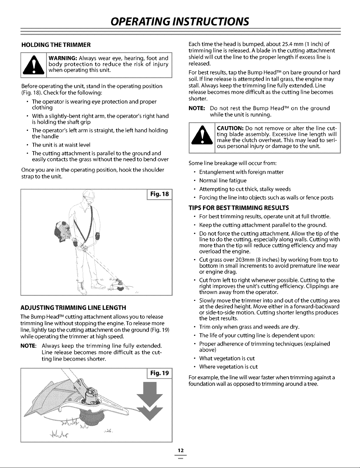
Before operating the unit, stand in the operating position
(Fig. 18). Check for the following:
• The operator is wearing eye protection and proper
clothing
• With a slightly-bent right arm, the operator's right hand
is holding the shaft grip
• The operator's left arm is straight, the left hand holding
the handle
• The unit is at waist level
• The cutting attachment is parallel to the ground and
easily contacts the grass without the need to bend over
Once you are in the operating position, hook the shoulder
strap to the unit.
i/ i\
ADJUSTING TRIMMING LINE LENGTH
The Bump Head TMcutting attachment allows you to release
trimming line without stopping the engine. To release more
line, lightly tap the cutting attachment on the ground (Fig. 19)
while operating the trimmer at high speed.
NOTE: Always keep the trimming line fully extended.
Line release becomes more difficult as the cut-
ting line becomes shorter.
Each time the head is bumped, about 25.4 mm (I inch) of
trimming line is released. A blade in the cutting attachment
shield will cut the line to the proper length if excess line is
released.
For best results, tap the Bump Head TMon bare ground or hard
soil. If line release is attempted in tall grass, the engine may
stall. Always keep the trimming line fully extended. Line
release becomes more difficult as the cutting line becomes
shorter.
NOTE: Do not rest the Bump Head TMon the ground
while the unit is running.
CAUTION: Do not remove or alter the line cut-
ting blade assembly. Excessive line length will
make the clutch overheat. This may lead to seri-
ous personal injury or damage to the unit.
Some line breakage will occur from:
• Entanglement with foreign matter
• Normal line fatigue
• Attempting to cut thick, stalky weeds
• Forcing the line into objects such as walls or fence posts
TIPS FOR BESTTRIMMING RESULTS
• For best trimming results, operate unit at full throttle.
• Keep the cutting attachment parallel to the ground.
• Do not force the cutting attachment. Allow the tip of the
line to do the cutting, especially along walls. Cutting with
more than the tip will reduce cutting efficiency and may
overload the engine.
• Cut grass over 203mm (8 inches) by working from top to
bottom in small increments to avoid premature line wear
or engine drag.
• Cut from left to right whenever possible. Cutting to the
right improves the unit's cutting efficiency. Clippings are
thrown away from the operator.
• Slowly move the trimmer into and out of the cutting area
at the desired height. Move either in a forward-backward
or side-to-side motion. Cutting shorter lengths produces
the best results.
• Trim only when grass and weeds are dry.
• The life of your cutting line is dependent upon:
• Proper adherence of trimming techniques (explained
above)
• What vegetation is cut
• Where vegetation is cut
For example, the line will wear faster when trimming against a
foundation wall as opposed to trimming around a tree.
12
OPERATING INSTRUCTIONS
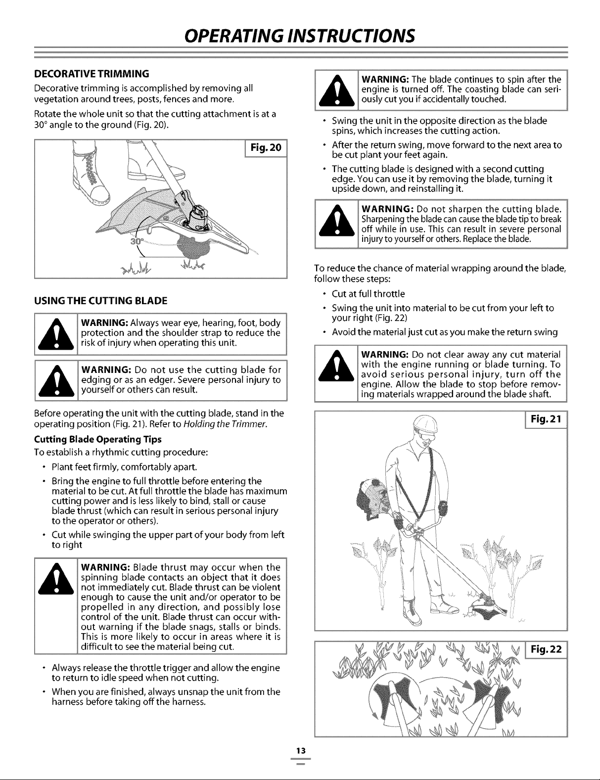
DECORATIVE TRIMMING
Decorative trimming is accomplished by removing all
vegetation around trees, posts, fences and more.
Rotate the whole unit so that the cutting attachment is at a
30 ° angle to the ground (Fig. 20).
I Fig. 20
USING THE CUTTING BLADE
WARNING: Always wear eye, hearing, foot, body
protection and the shoulder strap to reduce the
risk of injury when operating this unit.
WARNING: Do not use the cutting blade for
edging or as an edger. Severe personal injury to
yourself or others can result.
Before operating the unit with the cutting blade, stand in the
operating position (Fig. 21). Refer to Holding the Trimmer.
Cutting Blade Operating Tips
To establish a rhythmic cutting procedure:
• Plant feet firmly, comfortably apart.
• Bring the engine to full throttle before entering the
material to be cut. At full throttle the blade has maximum
cutting power and is less likely to bind, stall or cause
blade thrust (which can result in serious personal injury
to the operator or others).
• Cut while swinging the upper part of your body from left
to right
_G: Blade thrust may occur when the
spinning blade contacts an object that it does
not immediately cut. Blade thrust can be violent
enough to cause the unit and/or operator to be
propelled in any direction, and possibly lose
control of the unit. Blade thrust can occur with-
out warning if the blade snags, stalls or binds.
This is more likely to occur in areas where it is
difficult to see the material being cut.
• Always release the throttle trigger and allow the engine
to return to idle speed when not cutting.
• When you are finished, always unsnap the unit from the
harness before taking offthe harness.
Al-,...o,heba'e on'inue"o' ina er'he]
engine is turned off. The coasting blade can seri-
ously cut you if accidentally touched.
• Swing the unit in the opposite direction as the blade
spins, which increases the cutting action.
• After the return swing, move forward to the next area to
be cut plant your feet again.
• The cutting blade is designed with a second cutting
edge. You can use it by removing the blade, turning it
upside down, and reinstalling it.
WARNING: Do not sharpen the cutting blade.
Sharpening the blade can cause the blade tip to break
off while in use. This can result in severe personal
injury to yourself or others. Replace the blade.
To reduce the chance of material wrapping around the blade,
follow these steps:
• Cut at full throttle
• Swing the unit into material to be cut from your left to
your right (Fig. 22)
• Avoid the material just cut as you make the return swing
WARNING: Do not clear away any cut material
with the engine running or blade turning. To
avoid serious personal injury, turn off the
engine. Allow the blade to stop before remov-
ing materials wrapped around the blade shaft.
I Fig.21
Fig. 22
13
MAINTENANCE & REPAIR INSTRUCTIONS
MAINTENANCE SCHEDULE
Perform these required maintenance procedures at the
frequency stated in the table. These procedures should also
be a part of any seasonal tune-up.
NOTE:
Some maintenance procedures may require
special tools or skills. If you are unsure about
these procedures take your unit to any non-
road engine repair establishment, individual or
authorized service dealer.
WARNING: To prevent serious injury, never per-
form maintenance or repairs with unit running.
Always service and repair a cool unit. Disconnect
the spark plug wire to ensure that the unit can-
not start.
NOTE:
Maintenance, replacement, or repair of the emis-
sion control devices and system may be per-
formed by any non-road engine repair establish-
ment, individual or authorized service dealer.
In order to assure peak performance of your engine,
inspection of the engine exhaust port may be necessary after
50 hours of operation. If you notice lost RPM, poor
performance or general lack of acceleration, this service may
be required. If you feel your engine is in need of this
inspection, refer service to any non-road engine repair
establishment, individual or authorized service dealer for
repair. DO NOT attempt to perform this process yourself as
engine damage may result from contaminants involved in
the cleaning process for the port.
FREQUENCY MAINTENANCE REQUIRED REFER TO
Before starting engine Fill petrol tank with fresh petrol Page 10
Every 10 hours Clean and re-oil air filter Page 16
Check and clean spark arrestor Page 17
Every 25 hours
Check spark plug condition and gap Page 18
Every 50 hours Inspect exhaust port and spark arrestor screen for clogging or
obstruction to assure maximum performance levels Page 17
LINE INSTALLATION
This section covers both SplitLine TMand standard single line
installation.
Always use original equipment manufacturer 2.41 mm
(0.095 inch) replacement line. Line other than the specified
may make the engine overheat or fail.
There are two methods to replace the trimming line:
• Wind the inner reel with new line
• Install a prewound inner reel
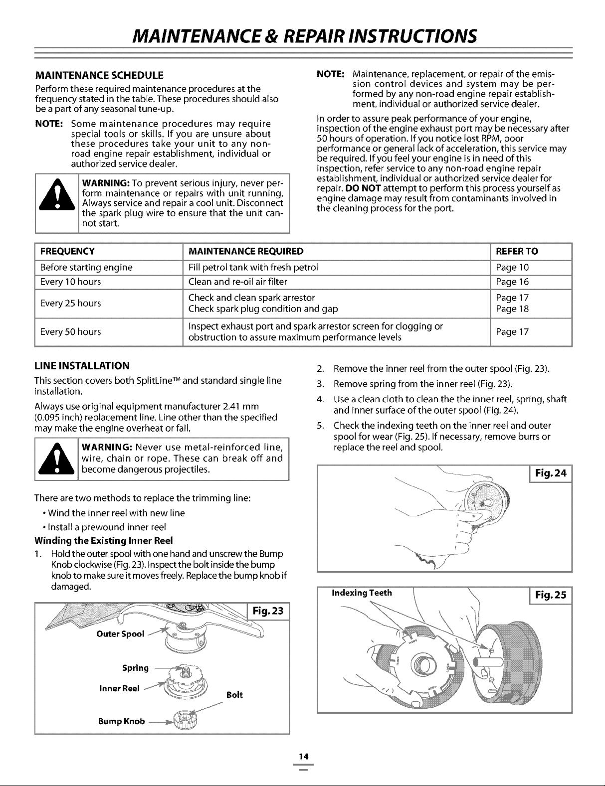
Winding the Existing Inner Reel
1. Hold the outer spool with one hand and unscrew the Bump
Knob clockwise (Fig. 23). Inspect the bolt inside the bump
knob to make sure it moves freely. Replace the bump knob if
damaged.
.23
Outer Spool _
Spring
Inner Reel Bolt
Bump Knob --
2. Remove the inner reel from the outer spool (Fig. 23).
3. Remove spring from the inner reel (Fig. 23).
4. Use a clean cloth to clean the the inner reel, spring, shaft
and inner surface of the outer spool (Fig. 24).
5. Check the indexing teeth on the inner reel and outer
spool for wear (Fig. 25). If necessary, remove burrs or
replace the reel and spool.
I Fig. 24
Indexing Teeth I Fig. 25
14
MAINTENANCE & REPAIR INSTRUCTIONS
........ • _ • z j¸
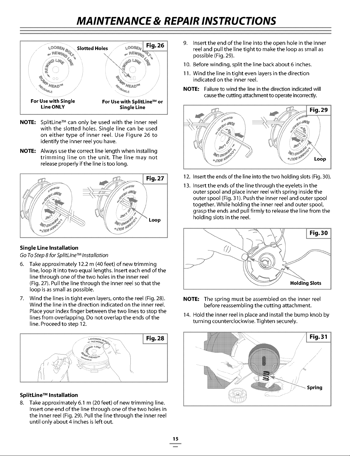
For Use with Single
Line ONLY
For Use with SplitLine TMor
Single Line
NOTE:
NOTE:
SplitLine TMcan only be used with the inner reel
with the slotted holes. Single line can be used
on either type of inner reel. Use Figure 26 to
identify the inner reel you have.
Always use the correct line length when installing
trimming line on the unit. The line may not
release properly if the line is too long.
Fig. 27
Loop
Single Line Installation
Go To Step 8 for SplitLine TMInstallation
6. Take approximately 12.2 m (40 feet) of new trimming
line, loop it into two equal lengths. Insert each end of the
line through one of the two holes in the inner reel
(Fig. 27). Pull the line through the inner reel so that the
loop is as small as possible.
7. Wind the lines in tight even layers, onto the reel (Fig. 28).
Wind the line in the direction indicated on the inner reel.
Place your index finger between the two lines to stop the
lines from overlapping. Do not overlap the ends of the
line. Proceed to step 12.
................_ I Fig. 28
SplitLine TMInstallation
8. Take approximately 6.1 m (20 feet) of new trimming line.
Insert one end of the line through one of the two holes in
the inner reel (Fig. 29). Pull the line through the inner reel
until only about 4 inches is left out.
9. Insert the end of the line into the open hole in the inner
reel and pull the line tight to make the loop as small as
possible (Fig. 29).
10. Before winding, split the line back about 6 inches.
11. Wind the line in tight even layers in the direction
indicated on the inner reel.
NOTE: Failure to wind the line in the direction indicated will
causethe cutting attachment to operate incorrectly.
Loop
12. Insert the ends of the line into the two holding slots (Fig. 30).
13. Insert the ends of the line through the eyelets in the
outer spool and place inner reel with spring inside the
outer spool (Fig. 31). Push the inner reel and outer spool
together. While holding the inner reel and outer spool,
grasp the ends and pull firmly to release the line from the
holding slots in the reel.
Fig. 30
Holding Slots
NOTE: The spring must be assembled on the inner reel
before reassembling the cutting attachment.
14. Hold the inner reel in place and install the bump knob by
tu rni ng cou nterclockwise. Tighten secu rely.
Spring
15
MAINTENANCE & REPAIR INSTRUCTIONS
INSTALLING A PREWOUND REEL
1. Hold the outer spool with one hand and unscrew the bump
knob clockwise (Fig. 23). Inspect the bolt inside the bump
knob to make sure it moves freely. Replace the bump knob if
damaged.
2. Remove the old inner reel from the outer spool (Fig. 23).
3. Remove the spring from the old inner reel (Fig. 23).
4. Place the spring in the new inner reel.
NOTE: The spring must be assembled on the inner reel
before reassembling the cutting attachment.
5. Insert the ends of the line through the eyelets in the
outer spool (Fig. 31).
6. Place the new inner reel inside the outer spool. Push the
inner reel and outer spool together. While holding the inner
reel and outer spool, grasp the ends and pull firmly to
release the line from the holding slots in the spool.
7. Hold the inner reel in place and install the bump knob by
turning counterclockwise. Tighten securely.
Replacement Parts
See Accessories / Replacement Parts.
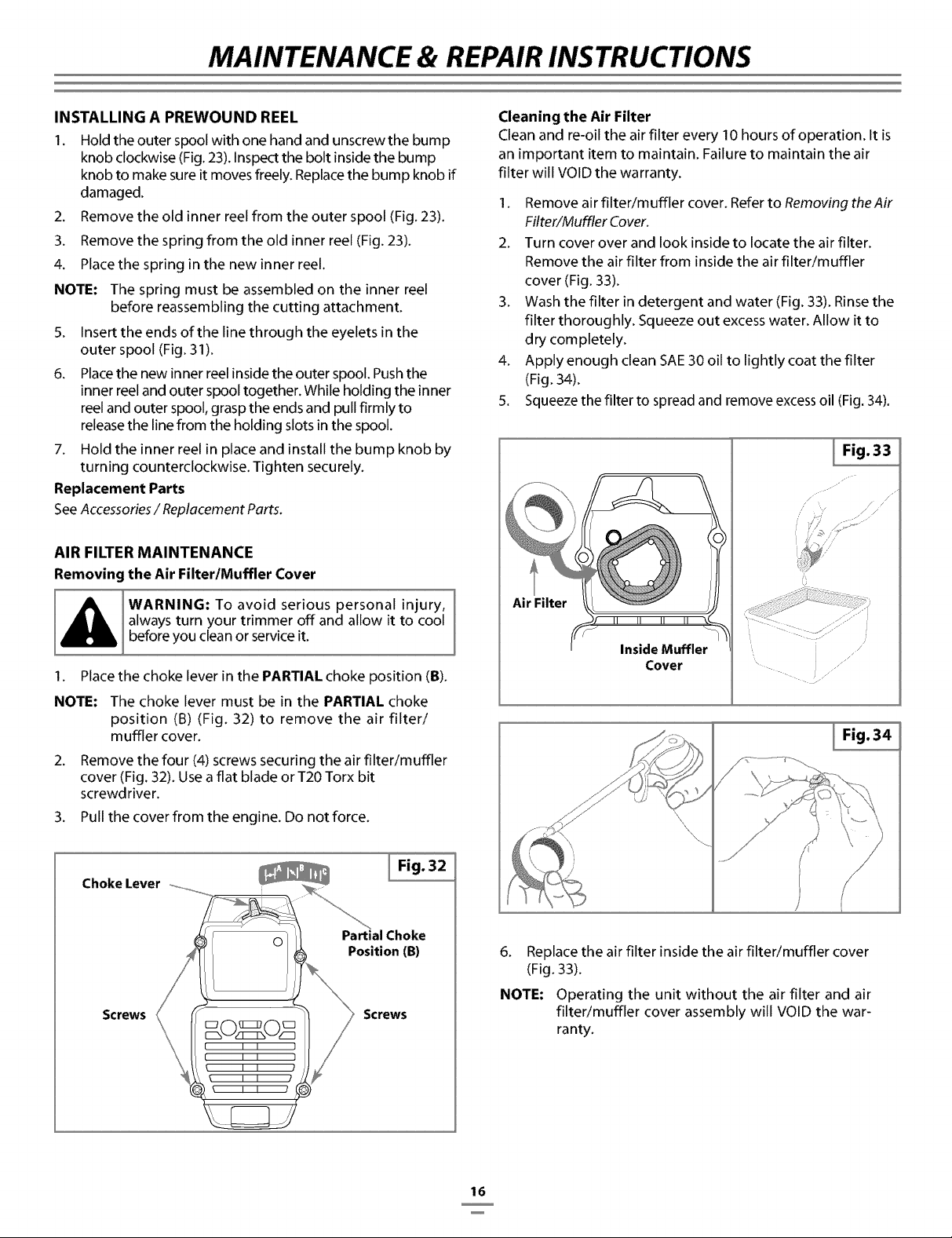
AIR FILTER MAINTENANCE
Removing the Air Filter/Muffler Cover
WARNING: To avoid serious personal injury,
always turn your trimmer off and allow it to cool
before you clean or service it.
1. Place the choke lever in the PARTIAL choke position (B).
NOTE: The choke lever must be in the PARTIAL choke
position (B) (Fig. 32) to remove the air filter/
muffler cover.
2. Remove the four (4) screws securing the air filter/muffler
cover (Fig. 32). Use a flat blade or T20 Torx bit
screwdriver.
3. Pull the cover from the engine. Do not force.
Choke Lever ..............
I Fig. 32
Screws
I I I I
\ I I I
\ I I /
I I /
Partial Choke
Position (B)
Screws
Cleaning the Air Filter
Clean and re-oil the air filter every 10 hours of operation. It is
an important item to maintain. Failure to maintain the air
filter will VOID the warranty.
1. Remove air filter/muffler cover. Refer to Removing theAir
Filter/Muffler Cover.
2. Turn cover over and look inside to locate the air filter.
Remove the air filter from inside the air filter/muffler
cover (Fig. 33).
3. Wash the filter in detergent and water (Fig. 33). Rinse the
filter thoroughly. Squeeze out excess water. Allow it to
dry completely.
4. Apply enough clean SAE 30 oil to lightly coat the filter
(Fig. 34).
5. Squeeze the filter to spread and remove excess oil (Fig. 34).
Air Filter
F
Inside Muffler
Cover
I Fig. 33
/
/ / /"
I Fig. 34
6. Replace the air filter inside the air filter/muffler cover
(Fig. 33).
NOTE: Operating the unit without the air filter and air
filter/muffler cover assembly will VOID the war-
ranty.
16
MAINTENANCE & REPAIR INSTRUCTIONS
Reinstalling the Air Filter/Muffler Cover
1. Place the air filter/muffler cover over the back of the
carburetor and muffler. Align the screw holes.
2. Insert the four (4) screws into the holes in the air
filter/muffler cover (Fig. 32) and tighten.
Do not over tighten,
1.
2.
SPARK ARRESTOR MAINTENANCE
Remove air filter/muffler cover. Refer to Removing theAir
Filter/Muffler Cover.
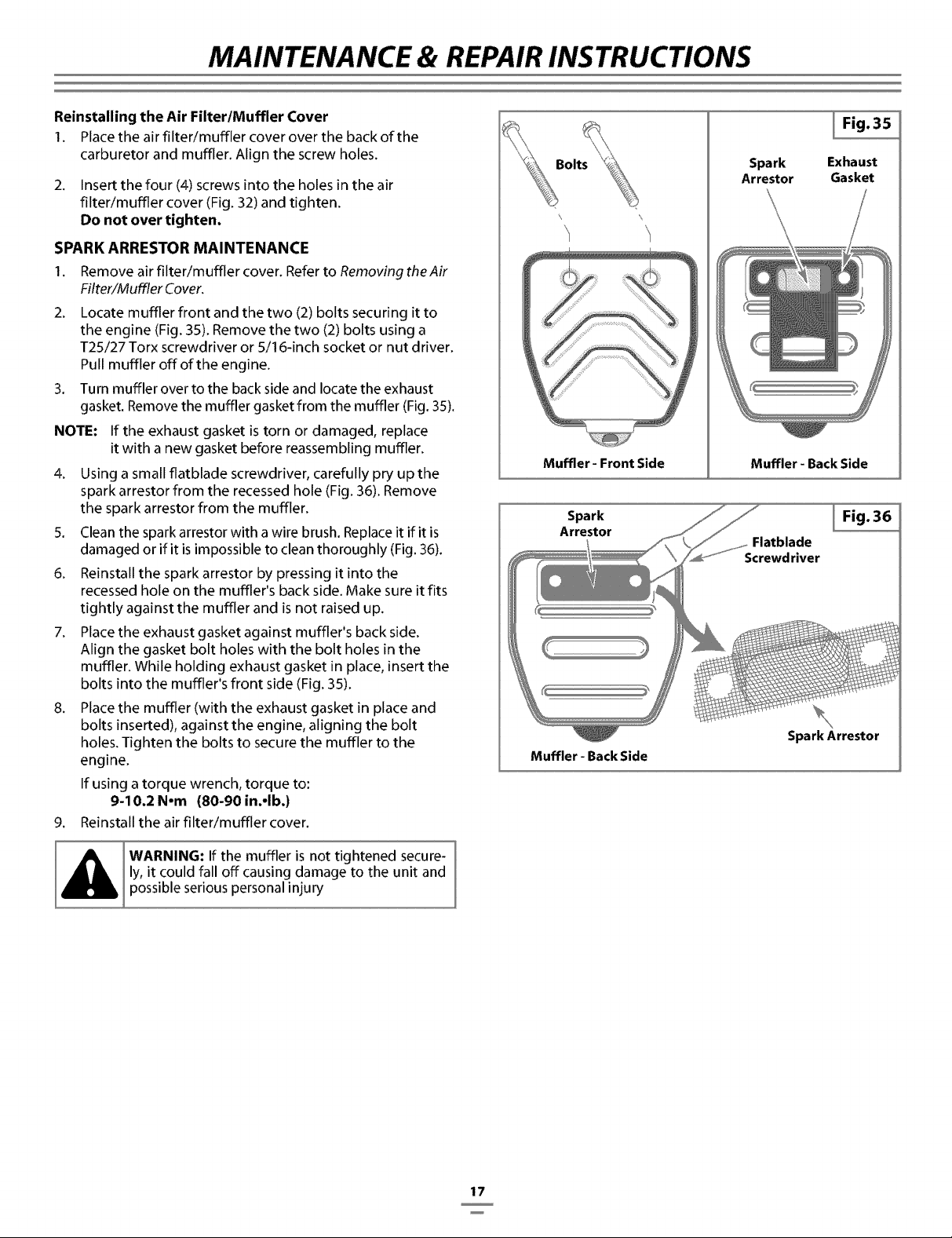
Locate muffler front and the two (2) bolts securing it to
the engine (Fig. 35). Remove the two (2) bolts using a
T25/27 Torx screwdriver or 5/16-inch socket or nut driver.
Pull muffler off of the engine.
3. Turn muffler over to the back side and locate the exhaust
gasket. Remove the muffler gasket from the muffler (Fig. 35).
NOTE: If the exhaust gasket is torn or damaged, replace
it with a new gasket before reassembling muffler.
4. Using a small flatblade screwdriver, carefully pry up the
spark arrestor from the recessed hole (Fig. 36). Remove
the spark arrestor from the muffler.
5. Clean the spark arrestor with a wire brush. Replace it if it is
damaged or if it is impossible to clean thoroughly (Fig. 36).
6. Reinstall the spark arrestor by pressing it into the
recessed hole on the muffler's back side. Make sure it fits
tightly against the muffler and is not raised up.
7. Place the exhaust gasket against muffler's back side.
Align the gasket bolt holes with the bolt holes in the
muffler. While holding exhaust gasket in place, insert the
bolts into the muffler's front side (Fig. 35).
8. Place the muffler (with the exhaust gasket in place and
bolts inserted), against the engine, aligning the bolt
holes. Tighten the bolts to secure the muffler to the
engine.
If using a torque wrench, torque to:
9-10,2 N-m (80-90 in.-lb.)
9. Reinstall the air filter/muffler cover.
WARNING: If the muffler is not tightened secure-
ly, it could fall off causing damage to the unit and
possible serious personal injury
\ \
Muffler - Front Side
I Fig. 35
Spark Exhaust
Arrestor Gasket
Muffler - Back Side
Spark
Arrestor
I Fig. 36
Muffler - Back Side
Spark Arrestor
17
MAINTENANCE & REPAIR INSTRUCTIONS
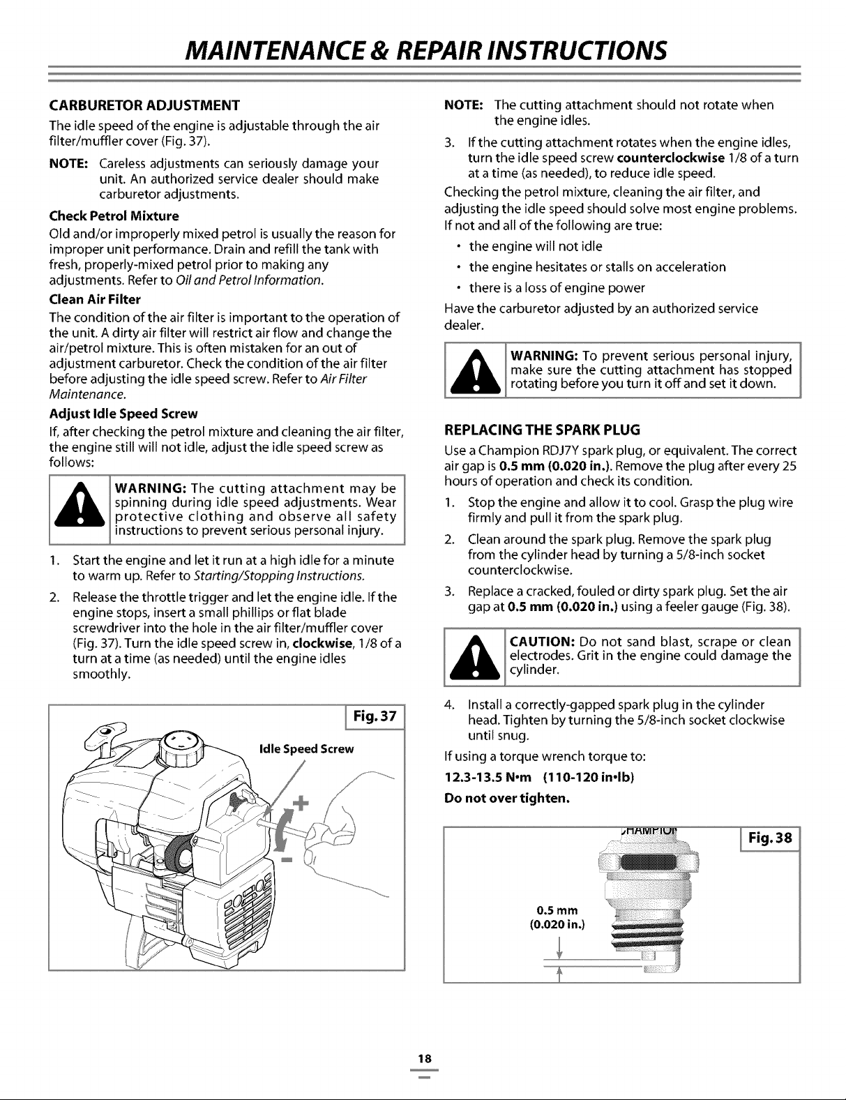
CARBURETOR ADJUSTMENT
The idle speed of the engine is adjustable through the air
filter/muffler cover (Fig. 37).
NOTE: Careless adjustments can seriously damage your
unit. An authorized service dealer should make
carburetor adjustments.
Check Petrol Mixture
Old and/or improperly mixed petrol is usually the reason for
improper unit performance. Drain and refill the tank with
fresh, properly-mixed petrol prior to making any
adjustments. Refer to Oil and Petrol Information.
Clean Air Filter
The condition of the air filter is important to the operation of
the unit. A dirty air filter will restrict air flow and change the
air/petrol mixture. This is often mistaken for an out of
adjustment carburetor. Check the condition of the air filter
before adjusting the idle speed screw. Refer to AirFilter
Maintenance.
Adjust Idle Speed Screw
If, after checking the petrol mixture and cleaning the air filter,
the engine still will not idle, adjust the idle speed screw as
follows:
WARNING: The cutting attachment may be
spinning during idle speed adjustments. Wear
protective clothing and observe all safety
instructions to prevent serious personal injury.
I.
2.
Start the engine and let it run at a high idle for a minute
to warm up. Refer to Starting/Stopping Instructions.
Release the throttle trigger and let the engine idle. If the
engine stops, insert a small phillips or flat blade
screwdriver into the hole in the air filter/muffler cover
(Fig. 37). Turn the idle speed screw in, clockwise, I/8 of a
turn at a time (as needed) until the engine idles
smoothly.
I Fig. 37
Idle Speed Screw
NOTE: The cutting attachment should not rotate when
the engine idles.
3. If the cutting attachment rotates when the engine idles,
turn the idle speed screw counterclockwise I/8 of a turn
at a time (as needed), to reduce idle speed.
Checking the petrol mixture, cleaning the air filter, and
adjusting the idle speed should solve most engine problems.
If not and all of the following are true:
• the engine will not idle
• the engine hesitates or stalls on acceleration
• there is a loss of engine power
Have the carburetor adjusted by an authorized service
dealer.
[ mWaAkReNluNr_:t_-eOcPrttve;taSttric°hUSePhOrsh_naltiongpreYci
[Airotatn0beoreyouturntoansettownI
REPLACING THE SPARK PLUG
Use a Champion RDJ7Y spark plug, or equivalent. The correct
air gap is 0.5 mm (0.020 in.). Remove the plug after every 25
hours of operation and check its condition.
I. Stop the engine and allow it to cool. Grasp the plug wire
firmly and pull it from the spark plug.
2. Clean around the spark plug. Remove the spark plug
from the cylinder head by turning a 5/8-inch socket
counterclockwise.
3. Replace a cracked, fouled or dirty spark plug. Set the air
gap at 0.5 mm (0.020 in.) using a feeler gauge (Fig. 38).
CAUTION: Do not sand blast, scrape or clean
electrodes. Grit in the engine could damage the
cylinder.
4. Install a correctly-gapped spark plug in the cylinder
head. Tighten by turning the 5/8-inch socket clockwise
until snug.
If using a torque wrench torque to:
12.3-13.5 Nom (110-120 inolb)
Do not over tighten.
I Fig. 38
0.5 mm
(0.020 in.)
18

MAINTENANCE & REPAIR INSTRUCTIONS
CLEANING
WARNING: To avoid serious personal injury,
always turn your trimmer off and allow it to cool
before you clean or service it.
Use a small brush to clean offthe outside of the unit. Do not
use strong detergents. Household cleaners that contain
aromatic oils such as pine and lemon, and solvents such as
kerosene, can damage plastic housing or handle. Wipe off
any moisture with a soft cloth.
STORAGE
• Never store a fueled unit where fumes may reach an
open flame or spark.
• Allow the engine to cool before storing.
• Store the unit locked up to prevent unauthorized use or
damage.
• Store the unit in a dry, well-ventilated area.
• Store the unit out of the reach of children.
LONG TERM STORAGE
If you plan on storing the unit for an extended time, use the
following storage procedure:
1. Drain all petrol from the petrol tank into a container with
the same 2-cycle petrol mixture. Do not use petrol that
has been stored for more than 60 days. Dispose of the
old petrol/oil mix in accordance to Federal, State and
Local regulations.
2. Start the engine and allow it to run until it stalls. This
ensures that all petrol has been drained from the
carburetor.
3. Allow the engine to cool. Remove the spark plug and put
30 ml (1 oz) of any high quality motor oil or 2-cycle oil
into the cylinder. Pull the starter rope slowly to distribute
the oil. Reinstall the spark plug.
NOTE: Remove the spark plug and drain all of the oil
from the cylinder before attempting to start the
trimmer after storage.
4. Thoroughly clean the unit and inspect it for any loose or
damaged parts. Repair or replace damaged parts and
tighten loose screws, nuts or bolts. The unit is ready for
storage.
TRANSPORTING
• Allow the engine to cool before transporting.
• Drain petrol from unit.
• Tighten petrol cap before transporting.
• Secure the unit while transporting.
ACCESSORIES/REPLACEMENT PARTS
2-Cycle Oil ......................................... 147543
Spark Plug ......................................... 610311
Spark Arrestor ...................................... 182747
Replacement Line .................................. 180120
Replacement Line Cartridge ........................ 147345
Bump Knob ........................................ 180814
Petrol Cap .......................................... 180000
Shoulder Strap ..................................... 160196
These replacement parts can be purchased from your local
authorized dealer.
19

TROUBLESHOOTING
ENGINE WILL NOT START
CAUSE
On/Off Stop Control is in OFF position
Empty petrol tank
Primer bulb wasn't pressed enough
Engine is flooded
Old or improperly mixed petrol
Fouled spark plug
Plugged spark arrestor
ACTION
Turn On/Off Stop Control to ON
Fill petrol tank with properly mixed petrol
Press primer bulb fully and slowly 10 times
Use starting procedure with choke lever in RUN
Drain petrol tank and add fresh petrol mixture
Replace or clean the spark plug
Clean or replace spark arrestor
ENGINE WILL NOT IDLE
CAUSE
Air filter is plugged
Old or improperly mixed petrol
Improper carburetor adjustment
ENGINE WILL NOT ACCELERATE
CAUSE
Old or improperly mixed petrol
Improper carburetor adjustment
Cutting attachment bound with grass
Dirty air filter
Plugged spark arrestor
ACTION
Replace or clean the air filter
Drain petrol tank and add fresh petrol mixture
Adjust according to the CarburetorAd]ustments section
ACTION
Drain petrol tank and add fresh petrol mixture
Take to an authorized service dealer for an adjustment
Stop the engine and clean the cutting attachment
Clean or replace the air filter
Clean or replace spark arrestor
ENGINE LACKS POWER OR STALLS WHEN CUTTING
CAUSE
Old or improperly mixed petrol
Improper carburetor adjustment
Fouled spark plug
Plugged spark arrestor
ACTION
Drain petrol tank and add fresh petrol mixture
Take to an authorized service dealer for an adjustment
Replace or clean the spark plug
Clean or replace spark arrestor
CUTTING ATTACHMENT WILL NOT ADVANCE LINE
CAUSE
Cutting attachment bound with grass
Cutting attachment out of line
Inner reel bound up
Cutting head dirty
Line welded
Line twisted when refilled
Not enough line is exposed
CUTTING LINE ADVANCES UNCONTROLLABLY
CAUSE
Oil, cleaner or lubricant in cutting head
ACTION
Stop the engine and clean cutting attachment
Refill with new line
Replace the inner reel
Clean inner reel and outer spool
Disassemble, remove the welded section and rewind
Disassemble and rewind the line
Push the bump knob and pull out line until 102 mm
(4 inches) of line is outside of the cutting attachment
ACTION
Clean and thoroughly dry the cutting head
If further assistance is required, contact your authorized service dealer.
20

SPECIFICATIONS
ENGINE
Engine Type ......................................................................................................................................................................................Air-Cooled, 2-Cycle
Stroke ................................................................................................................................................................................................31.75 turn (I .25 in.)
Displacement .........................................................................................................................................................................................31 cc (I .9 cu in)
Clutch Type ......................................................................................................................................................................................................Centrifugal
Idle Speed RPM..................................................................................................................................................................................2,800 - 4,400 rprn
Operating RPM .............................................................................................................................................................................................7,200+ rprn
Ignition Type ......................................................................................................................................................................................................Electronic
Ignition Switch .........................................................................................................................................................................................Rocker Switch
Spark Plug Gap.................................................................................................................................................................................0.5 turn (0.020 in.)
Lubrication .........................................................................................................................................................................................Petrol/Oil Mixture
Petrol/Oil Ratio .............................................................................................................................................................................................................40:1
Carburetor ...............................................................................................................................................................................Diaphragm, All-Position
Starter ............................................................................................................................................................................................................Auto Rewind
Muffler ................................................................................................................................................................................................Baffled with Guard
Throttle ........................................................................................................................................................................................Manual Spring Return
Petrol Tank Capacity ..............................................................................................................................................................................355 rnl (I 2 oz. )
DRIVE SHAFT and CUTTING ATTACHMENT
Drive Shaft Housing ......................................................................................................................................................................................Steel Tube
Throttle Control ...................................................................................................................................................Finger-Tip Trigger with Lock-Out
Approximate Unit Weight (No petrol, with cutting attachment, shield and handle) ........................................................7 kg (I S Ibs.)
Cutting Mechanism ............................................................................................................4-Tooth Cutting Blade, Dual String Cutting Head
Line Spool .......................................................................................................................................................................................Bump Line Releaser
Line Spool Diameter ...................................................................................................................................................................101.6 rnrn (4 inches)
Trimming Line Diameter .........................................................................................................................................................2.41 rnrn (0.095 inch)
Cutting Path Diameter, Cutting Attachment ......................................................................................................................45.7 cm (18 inches)
Cutting Path Diameter, Cutting Blade .....................................................................................................................................204 rnrn (8 inches)
Shoulder Harness ............................................................................................................................................................................Single Quick-Snap
21

PARTSLIST
ENGINE PARTS - MODEL BL250
2-CYCLE PETROL TRIMMER/BRUSHCUTTER
37
_38_
37
41
25_
26
37
;36_
Item
1
2
3
4
5
6
7
8
9
10
11
12
13
14
15
16
17
18
19
20
21
22
23
24
25
26
27
28
29
Pad No,
791-182059
791-180350B
791-180351
791-180226
753-04418
791-182161
753-04419
753-04333
791-610675
791-181860
791-683974B
753-1196
791-684451
753-1208
753-04470
791-612134
753-04311
791-182612
791-181168
791-682039
791-145308
791-182064
791-182736
791-181065
753-04232
791-613102
791-611061
791-181441
791-181079
Descr_tion
Air Cleaner/Muffler Cover Assembly
(includes 2 & 37)
Air Cleaner Filter
Carburetor Mounting Screws
Wavey Washer
Choke Lever Assembly (includes 6)
Choke Knob and Screw
Choke Lever and Plate (includes 5)
Carburetor Assembly (includes 9 & 21)
Carburetor Gasket
Carb Mount Screw
Primer and Hose Assembly
Carb Mount Assembly (includes 10, 13 & 14)
Reed Assembly
Carburetor Mount Gasket
Crank Case Service Assembly (includes 10)
Rear Mounting Pad
Petrol Tank Assembly (includes 18-20)
Petrol Cap Assembly
Petrol Return Line
Petrol Line Assembly
Front Mounting Pad
Shroud Extension and Stand
Flywheel Assembly
Spacer
Recoil Pulley Assembly
Recoil Spring
Rope Guide
Pulley Retainer Assembly
Pull Handle
Item
30
31
32
33
34
35
36
37
38
39
40
41
42
43
44
45
46
47
48
49
50
51
52
22
Pad No,
791-613103
753-04253
791-181862
791-182368
791-181445
791-153592
791-182797
791-181345
791-182519
791-182815
791-611063
753-04337
791-610311
753-04159
791-182066
791-147575
753-04323
753-04367
753-1197
791-182723
791-182747
753-04094
791-182409
753-04134
791-180090
791-180091
753-1209
753-04334
791-181599
Description
Rope
Starter Housing Assembly (includes 25-30, 32 & 37)
Housing Screw
Clutch Washer
Clutch Rotor Assembly (includes 33)
Clutch Drum Assembly
Clutch Cover Assembly
Cover Screw
Anti-Rotation Screw
Wire Leads
Ground Tab
Module Assembly (includes 40)
Spark Plug
Exhaust Gasket
Muffler Assembly
Muffler Mounting Bolt Assembly
Cylinder Assembly (includes 48 & 49)
Piston and Rod Assembly
Cylinder Gasket
Cylinder Bolt
Spark Arrestor Screen
Foot Stand
Washer
Engine Gasket Kit
O.E.M. Carburetor Repair Kit
Gasket Diaphragm Repair Kit
Piston Ring
Short Block Assembly
(includes 10, 15, 42, 47-50)
Clutch Springs (Qty. 2)
Items Not Shown

PARTSLIST
BOOM ANDTRIMMER PARTS - MODEL BL250
2-CYCLE PETROL TRIMMER/BRUSHCUTTER
Item Part No.
1 791-00040
2 791-00041
3 791-182690
4 791-00042
5 791-182405
6 791-180863
7 791-147346
8 791-180858
9 791-610327
10 753-04469
11 753-04103
12 791-612831
13 791-612021
14 753-04096
15 753-04097
16 791-182519
17 791-683295
18 791-181811
19 791-181812
20 791-181813
21 791-181814
22 791-181815
23 791-182816
24 791-181817
25 791-182200
26 791-182193
27 791-182195
28 791-147492
29 791-182196
30 791-683304
31 7911-683299
32 791-682061
33 791-147490
34 791-612483
35 791-683301
36 791-612026
37 791-610636B
38 791-147495
39 791-180814B
40 791-145873B
41 791-181699
* 791-160196
Description
Throttle Housing & Trigger
Assm (includes 2-4)
Throttle Trigger Lock-Out
Throttle Trigger Spring
Throttle Trigger
Switch Assembly
Wire Cover lft
Wire Tie
Foam Grip & Cover
Harness Clip
Upper Drive Shaft Housing Assembly
Bullhorn Handle Assembly
(includes 12-16)
Grip
Plug
Adapter
Cap
Anti-Rotation Screw
Handle Bracket Assembly
(includes 16 & 18-22)
Screw
Upper Handle Clamp
Middle Handle Clamp
Lower Handle Clamp
Nut
Throttle Cable
Flexible Drive Shaft
Shield Mount Screw Assembly
2 Piece Gearbox Assembly
(includes 16, 25, 27 & 29)
Gear Box Screw
Blade Shield/Shield Mount
Blade Driver
Shield Mounting Screw
Shield and Blade Assembly
(includes 32)
Blade Assembly
Retaining Washer
Spool Shaft
Outer Spool & Eyelet Assembly
Retainer
Spring
Inner Reel
Bump Head Knob Assembly
4-Tooth Blade
Nut
Shoulder Harness
@@i
2 Piece Gearbox Assembly Parts - Item 26
42 791-182191 Left Housing
43 791-182192 Right Housing
44 791-182194 Pinion Gear Assembly
45 791-182199 Output Shaft Bushing
46 791-182198 Output Shaft Gear
47 791-182197 Output Shaft Assembly (includes 45 & 46)
48 753-04348 Palnut
* 791-180014B Blade Retaining Kit (includes 33 & 41)
* 791-613226 Locking Rod Tool
Optional Accessories
* 791-180120 Replacement Line, 0.095 Diameter
* 791-147345B Reel and Line Assembly
* 791-147498B Bump Head Assembly (includes 34-39)
* Items Not Shown
23

MANUFACTURER'S LIMITED WARRANTY FOR:
The limited warranty set forth below is given by Troy-Bilt
LLC with respect with new merchandise purchased and
used in the United States, its possessions and territories.
Troy-Bilt warrants this product against defects in material
and workmanship for a period of two (2) years commencing
on the date of original purchase and will, at its option, repair
or replace, free of charge, any part found to be defective in
material or workmanship. This limited warranty shall only
apply if this product has been operated and maintained in
accordance with the Operator's Manual furnished with the
product, and has not been subject to misuse, abuse, com-
mercial use, neglect, accident, improper maintenance, alter-
ation, vandalism, theft, fire, water or damage because of
other peril or natural disaster. Damage resulting from the
installation or use of any accessory or attachment not
approved by Troy-Bilt for use with the product(s) covered by
this manual will void your warranty as to any resulting damage.
This warranty is limited to ninety (90) days from the date of
original retail purchase for any Bolens product that is used
for rental or commercial purposes, or any other income-pro-
ducing purpose.
HOW TO OBTAIN SERVICE: Warranty service is available,
WITH PROOF OF PURCHASE THROUGH YOUR LOCAL
AUTHORIZED SERVICE DEALER. To locate the dealer in your
area, please check for a listing in the Yellow Pages or con-
tact the Customer Service Department of Troy-Bilt LLC by
writing to PO Box 361131, Cleveland, Ohio 44136-0019. No
product returned directly to the factory will be accepted
unless prior written permission has been extended by the
Customer Service Department of Troy-Bilt LLC.
This limited warranty does not provide coverage in the
following cases:
A.Tune-ups - Spark Plugs, Carburetor Adjustments, Filters
B. Wear items - Bump Knobs, Outer Spools,Cutting Line,
Inner Reels, Starter Pulley, Starter Ropes, Drive Belts
C.Troy-Bilt does not extend any warranty for products
sold or exported outside of the United States of
America, its possessions and territories, except those
sold through Troy-Bilt's authorized channels of export
distribution.
Trot-Bilt reserves the right to change or improve the design of
any Bolens Product without assuming any obligation to modify
any product previously manufactured.
5_NCE o_85©
No implied warranty, including any implied warranty of
merchantability or fitness for a particular purpose,
applies after the applicable period of express written
warranty above as to the parts as identified. No other
express warranty or guaranty, whether written or oral,
except as mentioned above, given by any person or
entity, including a dealer or retailer, with respect to any
product shall bind Troy-Bilt LLC. During the period of
the Warranty, the exclusive remedy is repair or
replacement of the product as set forth above. (Some
states do not allow limitations on how long an implied warranty
lasts, so the above limitation may not apply to you.)
The provisions as set forth in this Warranty provide the
sole and exclusive remedy arising from the sales. Troy-Bilt
LLC shall not be liable for incidental or consequential loss
or damages including, without limitation, expenses
incurred for substitute or replacement lawn care services,
for transportation or for related expenses, or for rental
expenses to temporarily replace a warranted product.
(Some states do not allow limitations on how long an implied
warranty lasts, so the above limitation may not apply to you.)
In no event shall recovery of any kind be greater than the
amount of the purchase price of the product sold.
Alteration of the safety features of the product shall void
this Warranty. You assume the risk and liability for loss,
damage, or injury to you and your property and/or to others
and their property arising out of the use or misuse or inabili-
ty to use the product.
This limited warranty shall not extend to anyone other than
the original purchaser, original lessee or the person for
whom it was purchased as a gift.
Now State Law Relates to this Warranty: This warranty
gives you specific legal rights, and you may also have other
rights which vary from state to state.
TROY-BILT LLC
PO Box 361131
Cleveland, OH 44136-0019 U.S.A.
SAVE THESE INSTRUCTIONS FOR FUTURE REFERENCE
OPERATOR'S MANUAL PART NO. 769-00810
PRINTED IN U.S.A.
6/03