Loading ...
Loading ...
Loading ...
8 9
JUMP-STARTER
This unit is equipped with a Jump Starter Power Button that allows energy to flow
only when proper connections are made to the battery and frame.
A. For negative-grounded systems, connect the positive (red) clamp to the positive
ungrounded battery post and the negative (black) clamp to the vehicle chassis
or engine block away from the battery. Do not connect the clamp to the
carburetor, fuel lines or sheet-metal body parts. Connect to a heavy gauge
metal part of the frame or engine block.
B. For positive-grounded systems, connect the negative (black) clamp to the
negative ungrounded battery post and the positive (red) clamp to the vehicle
chassis or engine block away from the battery. Do not connect the clamp to
the carburetor, fuel lines or sheet-metal body parts. Connect to a heavy gauge
metal part of the frame or engine block.
IMPORTANT: Make sure the Compressor Power Button has been turned off before
attempting to use the unit as a Jump Starter.
WARNING – To reduce the risk of serious injury or property damage:
• Follow all safety instructions found in the “Specific Safety Instructions for Jump-
Starters” section of this instruction manual.
• Never touch red and black clamps together. This can cause dangerous sparks,
power arcing, and/or explosion.
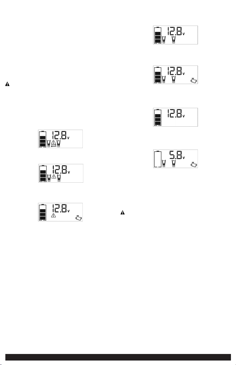
• If the clamps are connected incorrectly with regard to polarity, the unit will sound
a continuous alarm until the clamps are disconnected. The backlit LCD Screen will
display the Battery Status Icon, the Battery Voltage Indicator and the Clamp Icons.
The “+” and “–” signs above the Clamp Icons, the Arrow Icons and the Alarm Icon
will flash. The backlit LCD screen will display the following:
• If the red and black clamps touch each other, the unit will sound a continuous
two-second alarm every ten seconds until the clamps are separated. The backlit
LCD screen will display the following:
The Battery Status Icon and Battery Voltage Indicator light solid. The Alarm Icon,
Clamp Icons and the “+” and”–” signs will flash.
• If the unit is overheated during the jump starting process, the thermal protection
will activate and the backlit LCD screen will display the following:
The Battery Status Icon and Battery Voltage Indicator light solid. The Alarm Icon
and the jump starter icon will flash.
• Always disconnect the negative (black) jumper cable first, followed by the positive
(red) jumper cable, except for positive grounded systems.
Procedure
Take the following steps, observing all cautions and warnings in the “Important
Safety Instructions” section at the front of this manual.
1. Turn off vehicle ignition and all accessories (radio, A/C, lights, connected cell
phone chargers, etc.). Place vehicle in “park” and set the emergency brake.
2. Make sure the Jump-Starter Power Button is turned off.
3. Remove jumper clamps from clamp tabs. Connect the red clamp first, then the
black clamp.
4. Procedure for jump-starting a negative grounded system (negative battery
terminal is connected to chassis) (most common):
4a. Connect positive (+) red clamp to vehicle battery’s positive terminal.
4b. Connect negative (–) black clamp to chassis or a solid, non-moving, metal
vehicle component or body part. Never clamp directly to negative battery
terminal or moving part. Refer to the automobile owner’s manual.
5. Procedure for jump-starting positive ground systems:
NOTE: In the rare event that the vehicle to be started has a Positive Grounded System (positive battery
terminal is connected to chassis), replace steps 4a and 4b above with steps 5a and 5b, then
proceed to step 6.
5a. Connect negative (–) black clamp to vehicle battery’s negative terminal.
5b. Connect positive (+) red clamp to vehicle chassis or a solid, non-moving,
metal vehicle component or body part. Never clamp directly to positive
battery terminal or moving part. Refer to the automobile owner’s
manual.
6. When the clamps are connected properly, the backlit LCD screen will display
the following:
The Battery Status icon, Battery Voltage Indicator, Clamp Icons and the “+” and
“–” signs light solid.
7. Turn the Jump-Starter Power Button on. The backlit LCD screen will display the
following to indicate the unit is ready to jump-start:
The Battery Status icon, Battery Voltage Indicator, Clamp Icons and the “+” and
“–” signs light solid. The Jump Starter Icon will flash to indicate the clamps are
properly connected.
Note: If the Jump Starter Power Button has been pressed to turn the jump starter on and the clamps
are not connected to a battery, the backlit LCD screen will display the following:
The unit displays the Battery Status Icon and Battery Voltage Indicator for 10 seconds before
automatic shut down. Manufacturer suggests to always properly connect to a battery before
turning on the Jump Starter Power Button.
8. Turn on the ignition and crank the engine in 5-6 second bursts until engine
starts. The backlit LCD screen will display the following:
The Battery Status Icon, the Battery Voltage Indicator, Clamp Icons and the “+”
and”–” signs light solid to indicate the unit is jump-starting. The Jump Starter
Icon flashes. The Jump Starter Icon lights solid if vehicle is started.
9. Turn the Jump-Starter Power Button off.
10. Disconnect the negative (–) engine or chassis clamp first, then disconnect the
positive (+) battery clamp.
IMPORTANT: Always turn the unit off when not in use. Recharge this unit fully after
each use.
CAUTION – To reduce the risk of property damage:
• Vehicles that have on-board computerized systems may be damaged if vehicle
battery is jump-started. Before jump-starting this type of vehicle, read the vehicle
manual to confirm that external-starting assistance is advised.
• Excessive engine cranking can damage the vehicle‘s starter motor. If the engine
fails to start after the recommended number of attempts, discontinue jump-start
procedure and look for other problems that need to be corrected.
• If vehicle fails to start, turn off the ignition, turn off the Jump-Starter Power
Button, disconnect the jump-start system’s leads and contact a qualified technician
to investigate why the engine did not start.
AREA LIGHT
The area light is controlled by the Area Light Power Button on the Control Panel
(refer to the “Features” section to locate).
1. Press the Area Light Power Button once to turn the light on.
2. Press the Area Light Power Button again to turn the area light off.
When the Area Light Power Button is pressed to turn it on, a beep will sound. The
backlit LCD screen will turn on for 10 seconds (only) and will then continuously
display the Battery Status Icon and the Battery Voltage Indicator.
Periodically check the unit’s battery status on the backlit LCD screen. Four solid bars
in the battery icon indicates a full battery. When the battery level is nearly empty
with only one solid bar or completely empty with four empty bars, the unit must
be recharged at this time or the unit’s built-in low voltage protection will activate.
The empty Battery Status Icon will flash for a short period of time before automatic
shut down.
IMPORTANT: Make sure the Area Light is turned off when the unit is being
recharged or stored.
120 VOLT AC POWER OUTLET
Rated Versus Actual Current Draw of Equipment
Most electrical tools, appliances, electronic devices and audio/visual equipment
have labels that indicate the power consumption in amps or watts. Be sure that the
power consumption of the item to be operated is below 500 watts. If the power
consumption is rated in amps AC, simply multiply by the AC volts (120) to determine
the wattage.
Resistive loads are the easiest for this unit to run; however, it will not run larger
resistive loads (such as electric stoves and heaters), which require far more wattage
than the unit can deliver on a continuous basis. Inductive loads (such as TVs and
stereos) require more current to operate than do resistive loads of the same
wattage rating.
Power Inverter Output Waveform
The AC output waveform of this unit is known as a modified sine wave. It is a
stepped waveform that has characteristics similar to the sine wave shape of utility
power. This type of waveform is suitable for most AC loads, including linear and
switching power supplies used in electronic equipment, transformers, and small
motors.
Protective Features
The inverter monitors the following conditions:
Low internal battery voltage The inverter will automatically shut down when
the battery voltage drops too low, as this can
harm the battery.
High internal battery
voltage
The inverter will automatically shut down when
the battery voltage is too high, as this can harm
the unit.
Thermal shutdown
protection
The inverter will automatically shut down when
the unit becomes overheated.
Overload/short circuit
protection
The inverter will automatically shut down when an
overload or short circuit occurs.
IMPORTANT NOTES:
The AC Power Outlet provides a total power draw of 500W.
When the AC Power Outlet is in use, the unit will monitor for the following fault
conditions: thermal fault, low and high battery voltage fault, overload and short
circuit (refer to the “Protective Features” section).
1. If a low internal battery voltage fault condition exists, the AC Power Outlet will
shut down automatically and the backlit LCD screen will display the following
until the fault is corrected:
The Digital Display will show “AC”; the EMPTY Battery Status Icon and Fault
Icon on the LCD Screen will flash.
2. If the high internal battery voltage fault condition exists, the AC Power Outlet
will shut down automatically and the backlit LCD screen will display the
following until the fault is corrected:
The Digital Display will show “AC”; the FULL Battery Status Icon and Fault Icon
on the LCD Screen will flash.
3. If a thermal, overload or short circuit fault condition exists, the AC Power
Outlet will shut down automatically and the backlit LCD screen will display the
following until the fault is corrected:
The Battery Status Icon will light solid; the “AC” on the Digital Display and the
Fault Icon on the LCD Screen will flash.
Should any of the above fault conditions occur:
1. Disconnect the appliance from the unit.
2. Press the AC Power Button to turn the AC Power Outlet off.
3. Make sure the unit does not need to be recharged.
4. Allow the unit to cool down for several minutes.
5. Make sure the rating of the appliance plugged into the unit is 500 watts or
lower and that the appliance cord and plug are not damaged.
6. Assure there is adequate ventilation around the unit before proceeding.
Using the 120 Volt AC Outlet
The 120 Volt AC Outlet is located on the front of the unit. The outlet supports a
maximum power draw of 500 watts.
1. Press the AC Power Button to turn on the 120V AC Power Outlet. A beep will
sound and the LCD Screen will display the following:
The Battery Status Icon lights solid and the Digital Display shows “”AC”,
indicating the AC outlet is ready to use.
2. Insert the 120 volt AC plug from the appliance into the 120 Volt AC Outlet.
3. Switch on the appliance and operate as usual.
Note: Ensure that the wattage of the equipment plugged into the 120V AC Power Outlet does not
exceed 500 watts continuous.
4. Press the AC Power Button again to turn off the 120V AC Power Outlet.
Periodically check the unit’s battery status on the backlit LCD screen. Four solid bars
in the battery icon indicates a full battery. When the battery level is nearly empty
with only one solid bar or completely empty with 4 empty bars, the unit must be
recharged at this time or the unit’s built-in low voltage protection will activate. The
empty Battery Status Icon will flash for a short period of time before automatic
shut down.
IMPORTANT: Make sure the AC Power Outlet is turned off when the unit is being
recharged or stored.
USB PORTS
The USB Power Button and the three USB Ports are located on the front of the unit (refer to
the “Features” to locate).
IMPORTANT NOTES:
1. The three USB Ports provide 3.1A (5V) each.
2. When the USB Ports are in use, the unit will monitor for the following USB
fault conditions on all the USB Ports: low battery voltage fault, overload and
short circuit. In any of these cases, the backlit LCD screen will continuously
display the following:
The Fault Icon will flash. The USB Ports will automatically shut down. Should
this occur:
2a. Disconnect the USB-powered device and press the USB Power Button
again to turn off the USB Ports immediately.
2b. Make sure the unit does not need to be recharged.
2c. Allow the unit to cool down for several minutes before attempting to
use the USB Ports again.
2d. If a fault occurs again, make sure that the total draw of the USB device
plugged into the USB Port does not exceed 3.1A (5V). .
2e. If an individual USB device is within specifications and the fault occurs,
have the USB device checked for malfunction and do not continue to use
it with these USB Ports.
3. This unit’s USB Ports do not support data communication. They only provide
power to external USB-powered devices. The USB Ports provide 3.1A (5V) each.
4. Some household USB-powered electronics will not operate with this unit.
Using the USB Ports
1. Press the USB Power Button to turn on all of the USB Ports. A beep will sound.
The backlight will turn on for 10 seconds (only). The backlit LCD screen will
continuously display the following:
The Battery Status Icon and Battery Voltage Indicator will light solid, as well as
the USB Icon, indicating the USB ports are ready to use.
Loading ...
Loading ...
Loading ...