Solar Panel Installation and Maintenance
Manual
Renogy

1. Introduction ..........................................................................................1
2. Statutes and regulations ..................................................................... 1
3. General Information ............................................................................ 2
3.1. SolarPanelIdentication ..........................................................................................................2
3.2. Junctionboxstyleandwiringmethod ..................................................................................3
3.3. GeneralSafety ............................................................................................................................. 5
3.5. OperationSafety .........................................................................................................................6
3.6. FireProtectionandSafety ........................................................................................................ 7
4. Renogy solar panels installation method .......................................... 8
4.1. Installationlocationandenvironment ...................................................................................8
4.2. Selectionofinclinationangle ................................................................................................... 8
5. Renogy solar panels installation - Mechanical installation ...........10
5.1. GeneralRequirements ............................................................................................................. 10
5.2. Mechanicalmountingofsingle-sided&double-sidedcomponents ............................. 10
5.3. Introductionofexiblemoduleinstallationmethod ......................................................... 12
6. Renogy solar panels installation - Electrical installation ..............15
6.1. Electricalparameters ............................................................................................................... 15
6.2. CableandWiring........................................................................................................................ 15
6.3. Connector
................................................................................................................................... 16
6.4. BypassDiode ............................................................................................................................. 16
7. Renogy solar panels installation - Grounding .................................17
8. Renogy solar panels installation - Operation and maintenance ...18
8.1. Solarpanelcleaning ................................................................................................................. 18
8.2. VisualInspectionofPVPanels ............................................................................................... 18
8.3. InspectionoftheConnectorandtheCable ....................................................................... 19
9. Schedule - Renogy solar panel iteration/mix recommendation .. 20
Table of Contents
— 1 —
1. Introduction
Firstofall,thankyouverymuchforchoosingRenogy’ssolarpanels!
WhatshouldyoudowithRenogysolarpanelinstallationandmaintenance?Thisguidehas
coveredeverythingfromsolarpanelinstallationtocleaning.
Thisguidecontainsimportantelectricalandmechanicalinstallationinformationthatyou
shouldrstunderstandbeforeyouinstallthecomponents.Inaddition,themanualcontains
someothersafetyinformationthatyoumustbefamiliarwith.Everythinginthismanualisthe
resultofalongprocessoftechnicalexplorationandexperience
Failuretofollowtherequirementsoutlinedinthismanualmayvoidthelimitedwarranty
providedtothecustomerfortheinstallationofthecomponents.Therecommendationsin
thismanualaredesignedtoimprovethesafetyofthemodulesduringinstallationandhave
beentestedandproven.PleaseprovidethismanualtotheownerofthePVsystemfortheir
referenceandinformthemofallrelevantsafety,operationalandmaintenancerequirements
andrecommendations.
2. Statutes and regulations
ThemechanicalandelectricalinstallationofPVmodulesshouldrefertotheappropriate
regulations,includingelectricalcode,buildingcodeandelectricalconnectionrequirements.
Theseregulationsvarydependingonthelocationoftheinstallation,e.g.,buildingrooftop
installation,vehicle-mountedapplications,etc.Requirementsmayalsovarywiththevoltage
oftheinstallationsystem,thenatureofthecurrent(DCorAC).Pleasecontactyourlocal
authorityforspecicterms.
— 2 —
3. General Information
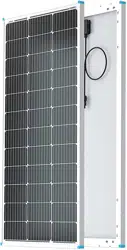
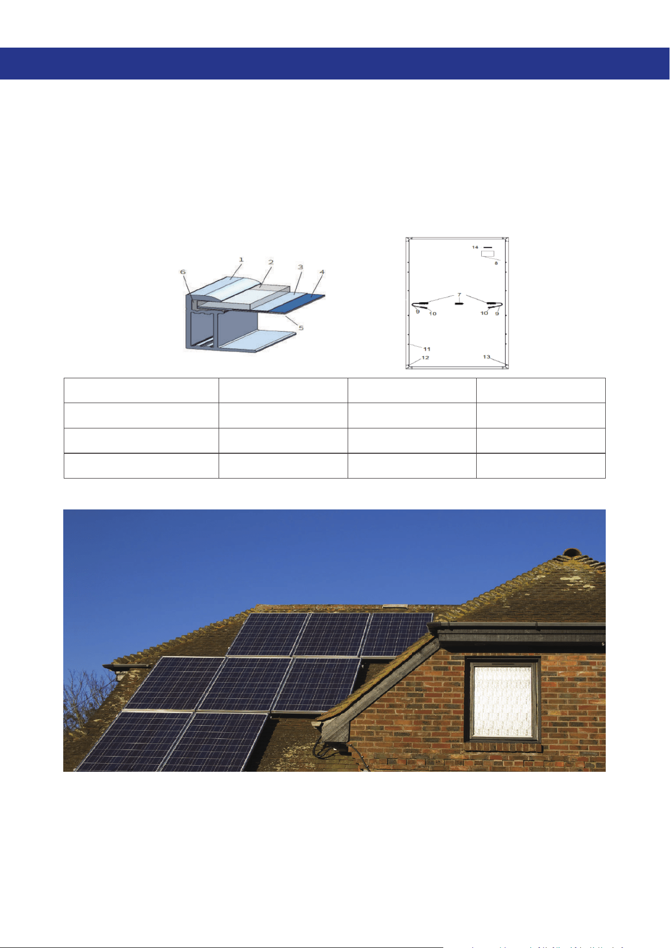
3.1. SolarPanelIdentication
Nameplate: Type,powerratingunderstandardtestconditions,currentrating,voltagerating,
opencircuitvoltage,shortcircuitcurrent,certicationmark,maximumsystemvoltage
information.
Serial Number: Eachcomponenthasauniqueserialnumber.Thisserialnumberisprinted
onabarcode,placedinthecomponentpriortolamination,andcannotbetornorsmeared
afterlamination.Inaddition,anidenticalserialnumbercanbefoundaboveornexttothe
componentnameplate.
1.Aluminumalloyframe 2.PVGlass 3.EVA 4. Solar Cell
5.Backplate 6.Silicone 7.JunctionBox 8.Nameplate
9.CableWires 10.Connector 11.Mountingholes 12.Groundinghole
13.Leakagehole 14. Bar Code
(Therestoftheversionacorrespondingsolarpanelspecicationsshallprevail)
— 3 —
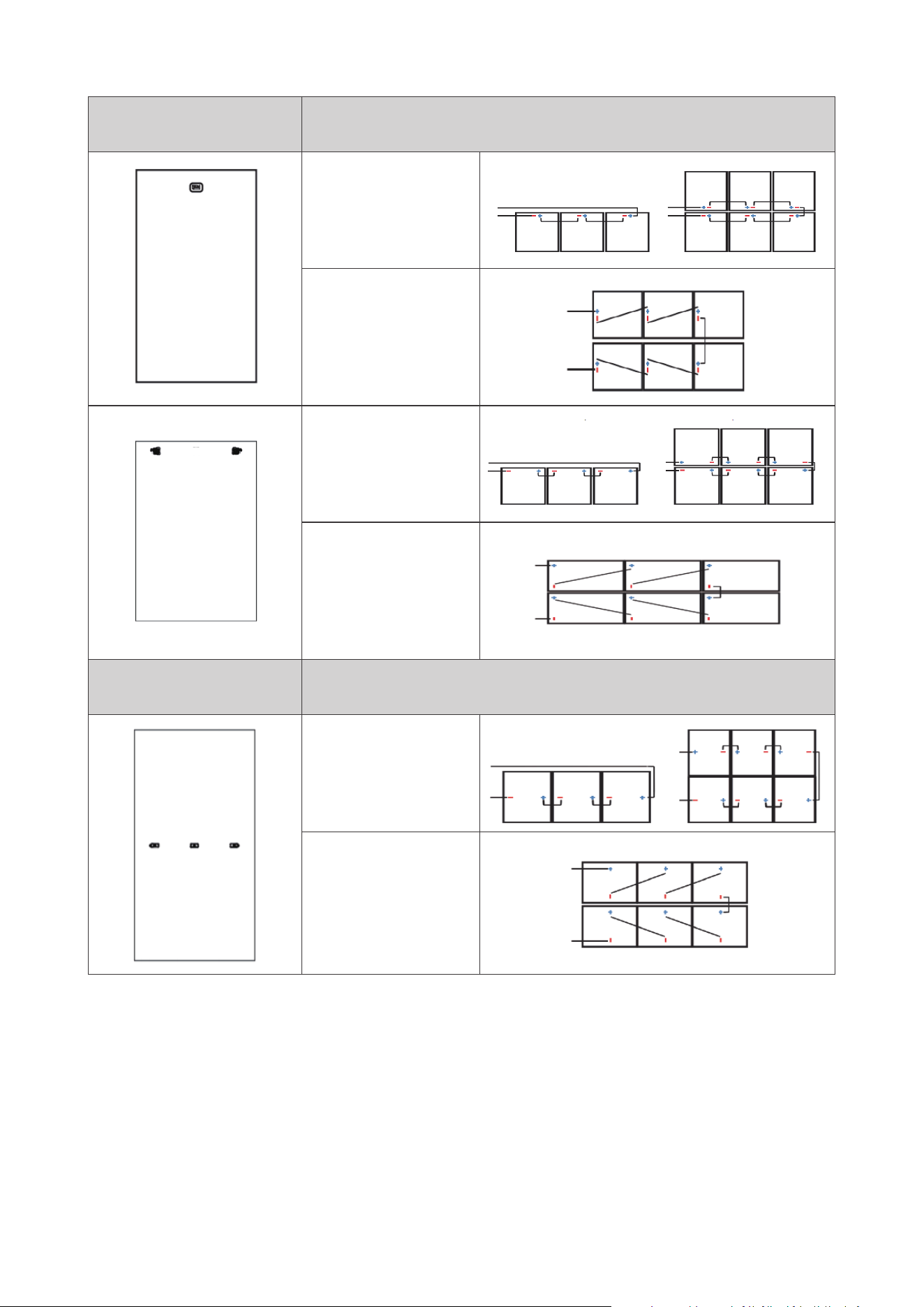
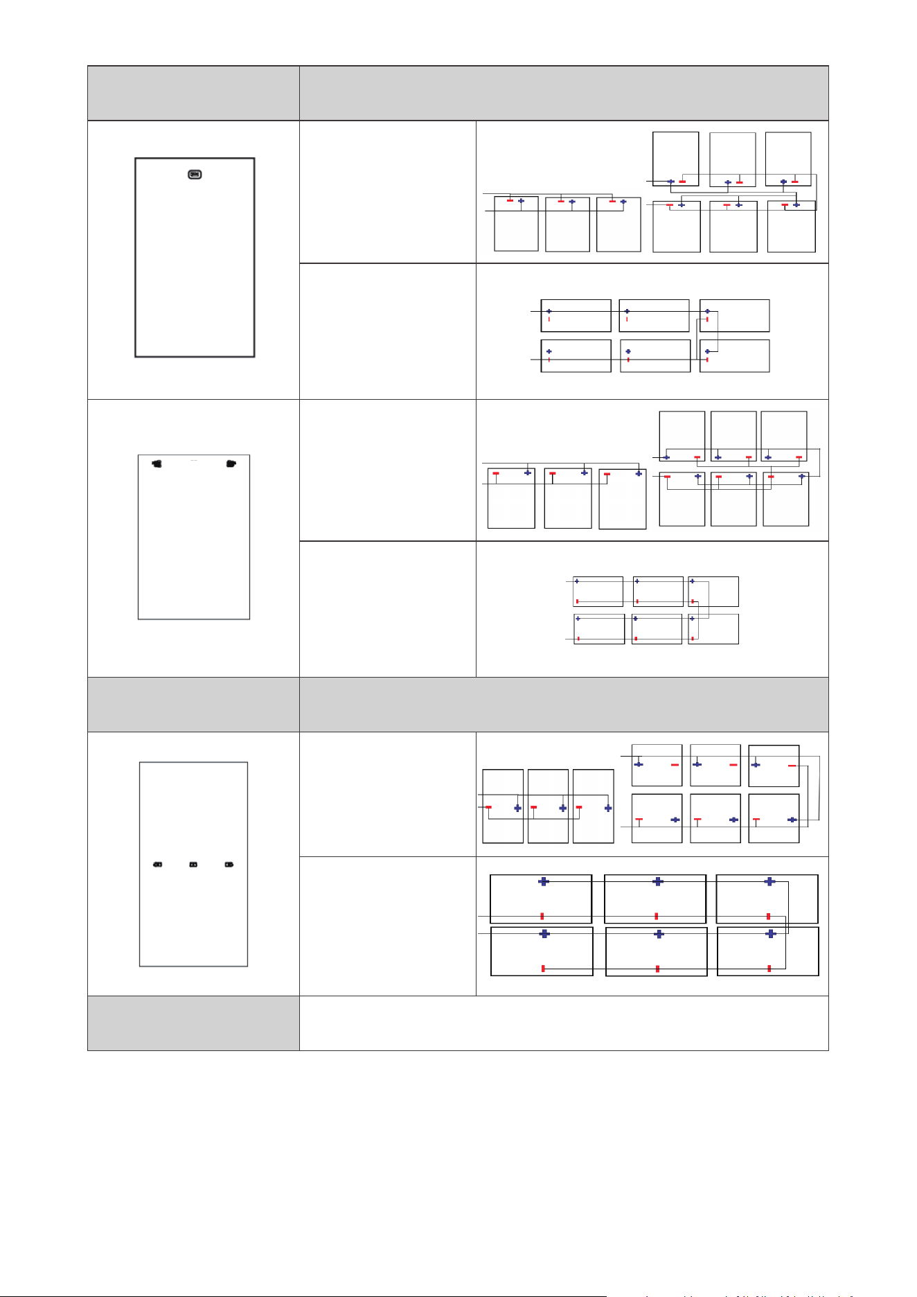
3.2. Junction box style and wiring method
Junction box location
Recommended connection & wiring method for series
connection
Verticalinstallation:
thestandardline
lengthcanbe(Note:
canincreasethe
extensionline)
Horizontal
installation:
standardlinelength
canbe(Note:
canincreasethe
extensionline)
Verticalinstallation:
thestandardline
lengthcanbe(Note:
canincreasethe
extensionline)
Horizontal
installation:
standardlinelength
canbe(Note:
canincreasethe
extensionline)
Junction box location
Recommended connection & wiring method for series
connection
Verticalinstallation:
thestandardline
lengthcanbe(Note:
canincreasethe
extensionline)
Horizontal
installation:
standardlinelength
canbe(Note:
canincreasethe
extensionline)
— 4 —
Junction box location
Recommended connection & wiring method for parallel
connection
Verticalinstallation:
thestandardline
lengthcanbe(Note:
canincreasethe
extensionline)
Horizontal
installation:
standardlinelength
canbe(Note:
canincreasethe
extensionline)
Verticalinstallation:
thestandardline
lengthcanbe(Note:
canincreasethe
extensionline)
Horizontal
installation:
standardlinelength
canbe(Note:
canincreasethe
extensionline)
Junction box location
Recommended connection & wiring method for parallel
connection
Verticalinstallation:
thestandardline
lengthcanbe(Note:
canincreasethe
extensionline)
Horizontal
installation:
standardlinelength
canbe(Note:
canincreasethe
extensionline)
Attention & Notes
Thistableisforreferenceonly,theactualwiringdependsonthe
situation,trytoreducethelengthoftheline,avoidcross-wiring.
— 5 —
3.3. General Safety
Whenthemodulesareinstalledontheroof,theoverallreratingofthenalstructureneeds
tobeconsidered.Also,theoverallmaintenanceafterwardsneedstobeconsidered.Foryour
safety,donotworkontheroofwithoutsafetyprecautionsincluding,butnotlimitedto,fall
protection,laddersorstairsandpersonalprotectiveequipment.Foryoursafety,donotinstall
orhandlecomponentsinhazardousenvironments,includingbutnotlimitedtostrongwindsor
gusts,wetorsandyroofs.
3.4. Electrical safety
Photovoltaicproductsgeneratedirectcurrentunderlightconditions,sotakeappropriate
protectivemeasures(insulatedgloves,insulatedshoes,etc.)toavoiddirectcontactbetween
personneland30VorhigherDCvoltages.30VorhigherDCvoltagesarepotentiallyfatal.
Componentscanalsogeneratevoltagewhennoloadorexternalcircuitisconnected.Use
insulatedtoolsandwearrubbergloveswhenhandlingthemodulesinthesun.
Photovoltaicmodulesdonothaveswitches.Themodulecanonlybemadetostopworking
bymovingthePVmoduleawayfromthelightorbycoveringitwithcloth,cardboardora
completelyopaquematerial.
Toavoidarcingandelectricshockhazards,donotdisconnectelectricalconnectionswitha
load.Incorrectconnectionscanalsocausearcingandelectricshock.Connectorsmustbe
keptdryandcleantoensuretheyareingoodworkingcondition.Donotinsertothermetal
objectsintotheconnectorsormakeelectricalconnectionsinanyotherway.
Snowandwaterorotherreectionsfromthesurroundingenvironmentcanincreasethe
intensityoftheirradiationreceivedbythemoduleandcancauseanincreaseinoutput
current.Theoutputvoltageofthemodulewillalsoincreaseappropriatelyatlowtemperatures.
— 6 —
Ifthemoduleglassorotherencapsulationmaterialisdamaged,wearpersonalprotective
equipmentandseparatethemodulefromthecircuit.
Touchingwetcomponentsisstrictlyforbiddenunlesswearingshockprotectionequipment
thatmeetstherequirements;whencleaningcomponents,youmustfollowtherequirements
ofthismanualforcleaningcomponents.
Theconnectormustnotcomeintocontactwiththefollowingchemicals:gasoline,white
oweroil,liveoil,moldtemperatureoil,motoroil(e.g.KV46),grease(e.g.MolykoteEM-50L,
etc.),lubricatingoil,rustpreventionoil,stampingoil,grease,dieseloil,cookingoil,acetone,
alcohol,windex,orthobonewater,tenax,moldreleaseagents(e.g.PelicoatS-6,etc.),sticky
boardadhesiveandpottingSealant(suchasKE200,CX-200,chemlok,etc.),TBP(plasticizer),
cleaningagent,etc.
3.5. Operation Safety
z
Toensurethesafetyofthecomponentsduringtransportationand
storage,unpackthecomponentsuponarrivalattheinstallationsite.
z
Protectthepackagingfromdamageordropping.
z
Itisforbiddenunderanycircumstancestolifttheentiremoduleby
graspingthejunctionboxorwires.
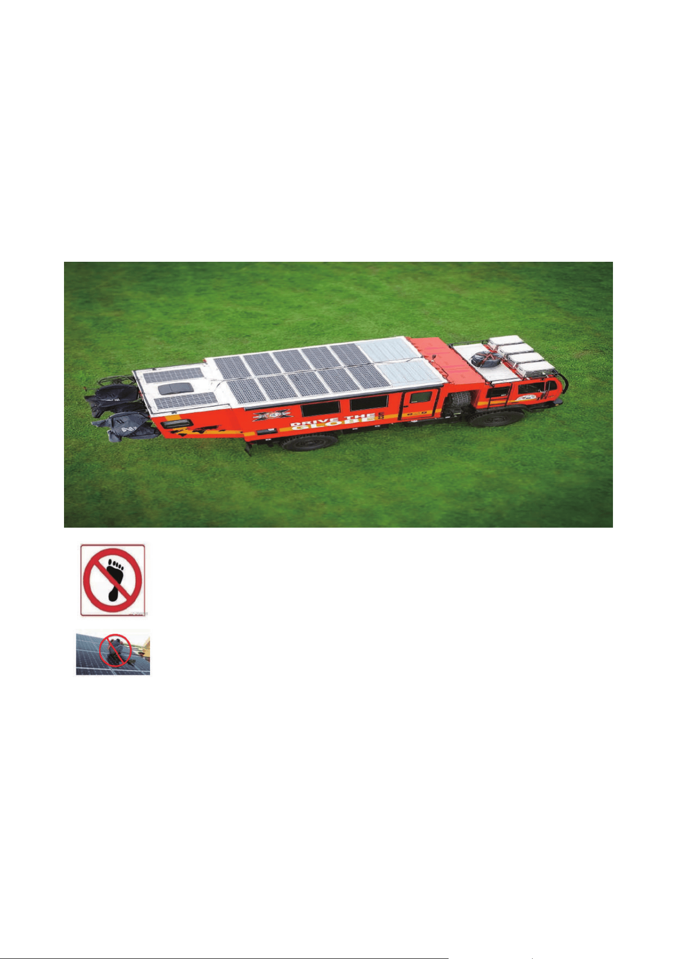
z
Donotstandorwalkonthemodule.
z
Donotapplyexcessiveloadsonthemoduleortwistthemoduleinorder
toavoidglassbreakage.
z
Donotdrillholesinthemodulebezel,asthiswillresultinareductionin
thebezel’sresistancetoloadandleadtocorrosionofthebezel,thereby
voidingthewarranty;
z
Donotscratchtheanodicoxidelayeronthesurfaceofthealuminum
bezel,exceptwhengroundingconnectionsaremade.Scratchingmay
leadtoframecorrosion,aectingtheframe’sloadresistanceandlong-
termreliability.
z
Self-repairofcomponentsisstrictlyprohibited
— 7 —
3.6. Fire Protection and Safety
Pleaserefertolocallawsandregulationsbeforeinstallingthecomponentsandcomplywith
themregardingbuildingreresistancerequirements.Ensureadequateventilationbetween
thebacksheetandtheinstallationsurfaceduringinstallation.Thestructureoftheroofand
thewayitisinstalledcanaecttheresafetyperformanceofthebuilding.Ifnotproperly
installed,aremayresult.Toensurethereratingontheroof,theminimumdistancebetween
themoduleframeandtheroofsurfaceis10cm.Whenmountingthemoduleontheroofofa
vehicle,ifbracketsareused,themodulemustbemountedonthebracketsandmustnotbe
tightlybondedtotheroofitself.Usepropermoduleaccessoriessuchasfuses,circuitbreakers,
andgroundconnectorsasrequiredbylocalcodes.Donotusethemoduleifthereareexposed
combustiblegasesinthevicinity.
— 8 —
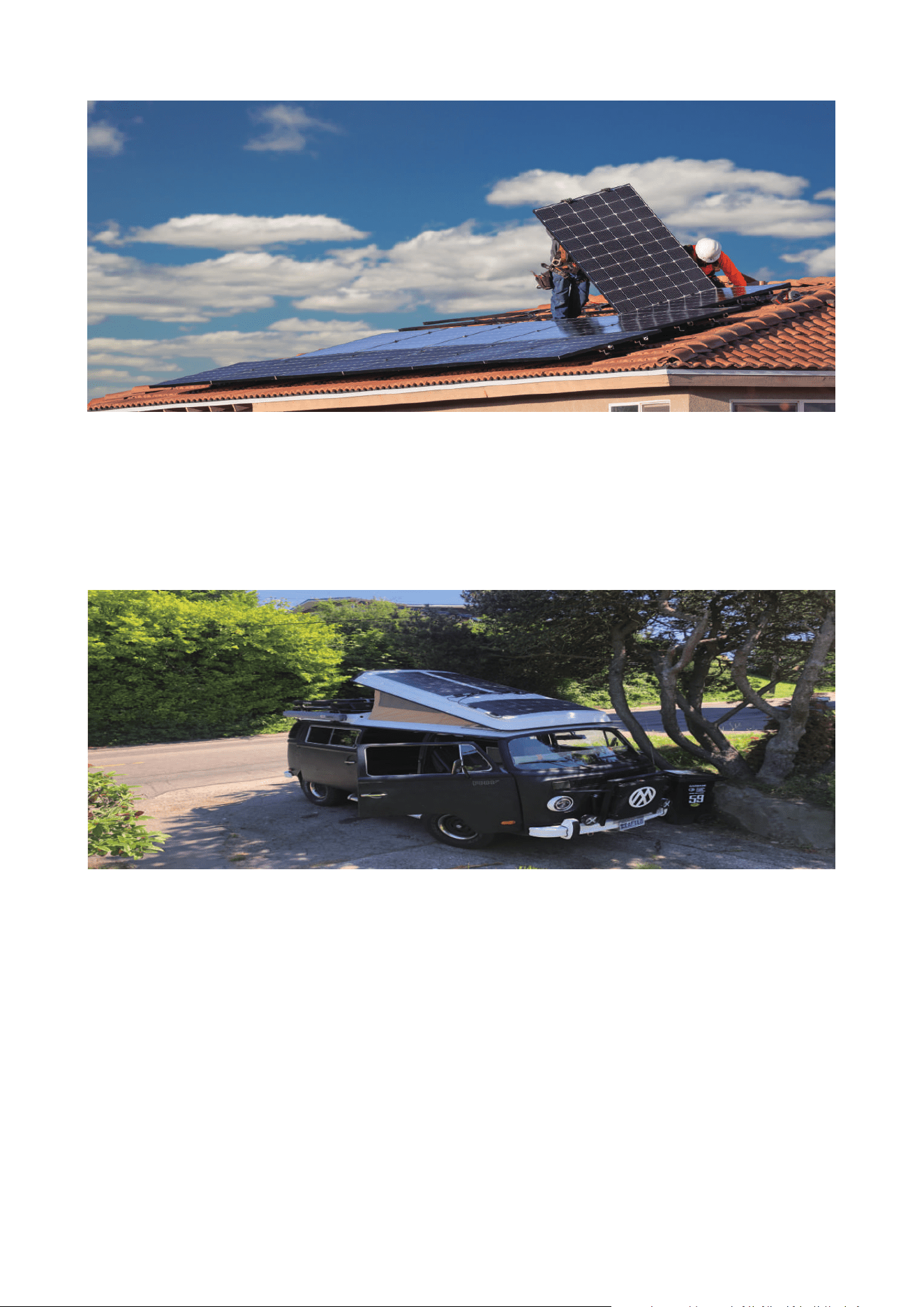
4. Renogy solar panels installation method
4.1. Installation location and environment
Thecomponentsarenotsuitableforspaceenvironment.
Donotusemirrorsormagnifyingglassestoarticiallyfocussunlightonthemodules.
Donotinstallthemoduleinalocationwherethereisariskofwaterooding.
Itisrecommendedthatthemodulesbeinstalledinanambientoperatingtemperatureof-40°C
to40°C,whichistheaveragemonthlymaximumandminimumtemperatureattheinstallation
site.Themaximumambientoperatingtemperatureofthemoduleis-40°Cto85°C.
Ensurethatthemoduleisnotsubjectedtowindorsnowpressureexceedingthemaximum
allowableloadafterinstallation.
Themoduleneedstobeinstalledinalocationwherethereisnoshadeallyearround.Make
surethattherearenoobstaclesthatmayblockthelightatthemoduleinstallationsite.
Ifthemodulesareinstalledinalocationwherethereisfrequentlightningactivity,themodules
mustbeprotectedfromlightningstrikes.
Donotinstallandusemodulesnearamesorcombustiblematerials.
Modulesmustnotbeinstalledorusedinenvironmentssubjecttoexcessivehail,snow,sand,
soot,airpollution,soot,etc.
Componentsarestrictlyforbiddentobeinstalledontheinstallationsurfacethatissusceptible
toagingandcorrosionbytheenvironment.Forexample:wood,PVCplastic,etc.
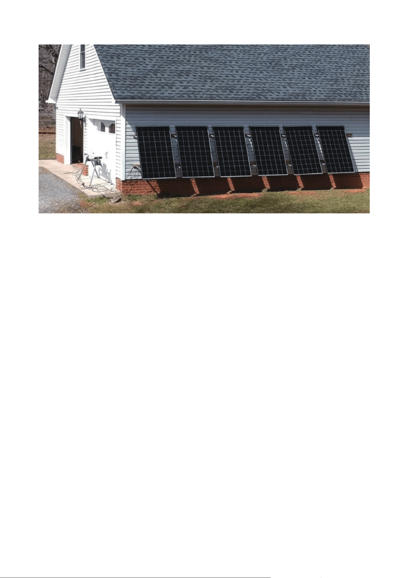
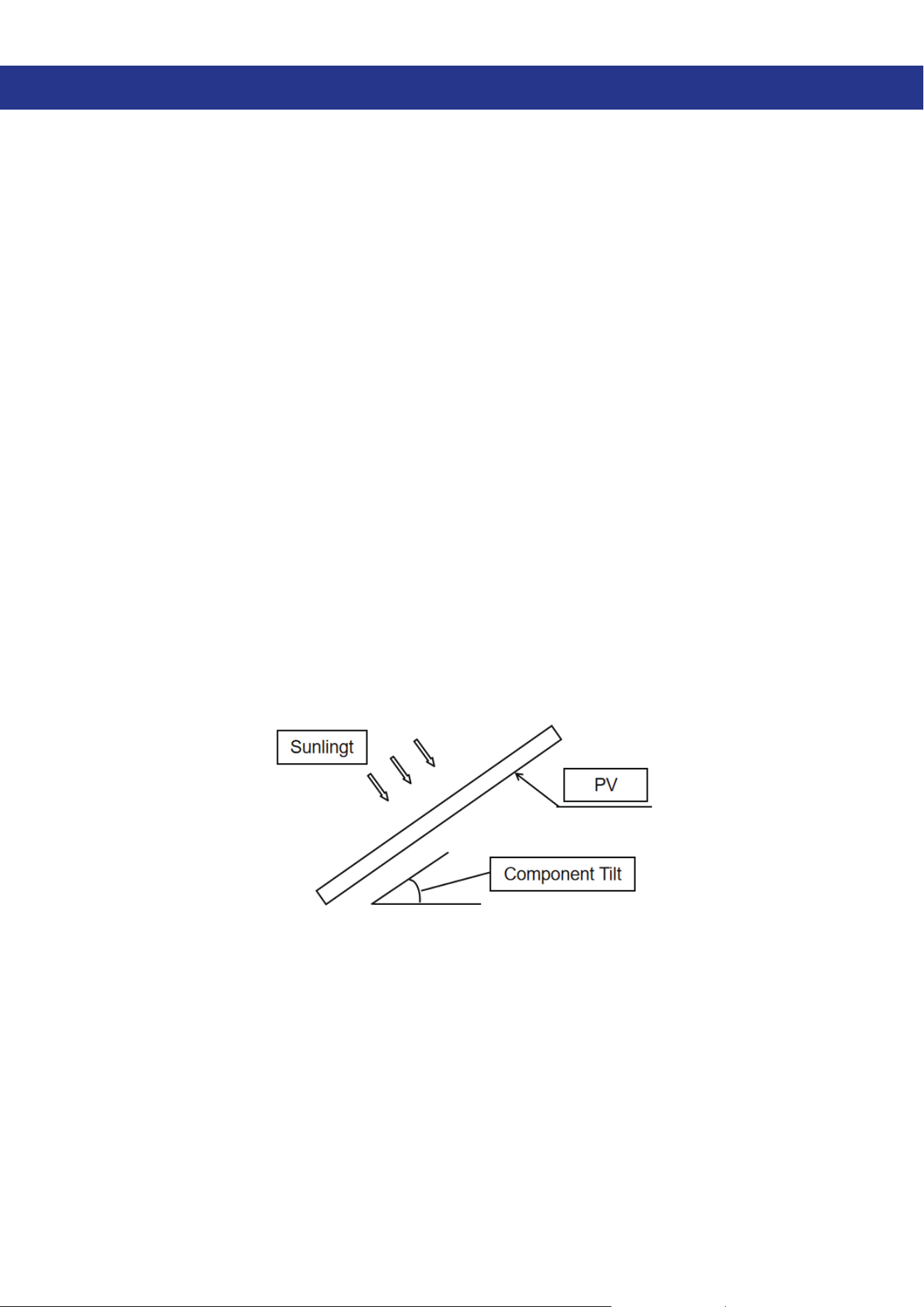
4.2. Selection of inclination angle
Moduleinclination:Theanglebetweenthesurfaceofthemoduleandthehorizontalplane.
Whenthemoduleisfacingthesunlight,themodulewillgetthemaximumpoweroutput.
ForinstallationintheNorthernHemisphere,modulesshouldpreferablyfacesouth,andfor
installationintheSouthernHemisphere,modulesshouldpreferablyfacenorth.
Fordetailedinstallationangles,pleasefollowthestandardmoduleinstallationguidelinesor
therecommendationsgivenbyexperiencedPVmoduleinstallers.
Itisrecommendedthatthemountingangleofthemodulesbenotlessthan10degrees(RV
dependingontheactualsituation),sothatthesurfacedustofthemodulescanbeeasily
carriedawaybyrainwaterwhenitrains,thusreducingthenumberofmodulecleaning;atthe
sametime,itisconducivetotheowofwateronthesurfaceofthemodules,avoidingalarge
amountofwaterfromaccumulatingontheglassforalongperiodoftimeandleavingmarks
ontheglass,whichinturnaectstheappearanceandperformanceofthemodules.
Seriallyconnected/parallelconnectedmodulesshouldbeinstalledinthesameorientationand
angle.Iftheorientationorangleisdierent,itmaycausedierentamountofsolarradiation
receivedbyeachmodule,whichmayleadtooutputpowerloss.Toachievemaximumannual
— 9 —
powerproduction,theoptimalorientationandtiltofthePVmodulesintheareawheretheyare
installedshouldbeselectedtoensurethatsunlightcanstillreachthemodulesevenonthe
shortestsunnydayoftheyear.
Ifconnectedtoastand-alonePVsystem,theangleofinstallationofthemodulesshould
bebasedontheseasonandlightconditionstoobtainmaximumpoweroutput.Generally
speaking,iftheoutputofthemodulescanbemetevenonthelowestlightintensityofthe
year,thentheoutputofthemodulesatthechosenanglewillmeettheyear-rounddemand.
— 10 —
5. Renogy solar panels installation - Mechanical installation
5.1. General Requirements
z
PVpanelscanbeinstalledverticallyorhorizontally,andpleasekeepthedrainholesonthe
frameunblocked.
z
PleasekeepthebackboardofthePVpanelsuntouchedwithanyotherstructuresespecially
whenthereareexternalpressureonthem.
z
Pleaseleaveatleast10mmgapbetweenPVpanelsincaseofanypotentialdamagecaused
bythermalexpansionandcontraction.
z
Pleaseassuretheinstallationsite,suchastheroofofthehouseorRV,isproperlysealed
andappropriateforinstallationincaseofunexpectedproblemsandpermeating.
z
Pleaseleavea10cmclearancebetweentheframeofPVpanelsandtherooforthewallto
securetheventilationanddissipationofmoisturewhenthePVpanelsareinstalledonthe
mountingbracketsparalleltothewallortheroof.
z
PleaseensurethePVpanel(s)ismountedrmlyontheroofofthehouseorRV.
5.2. Mechanical mounting of single-sided & double-sided components
Renogycurrentlyoerscomponentsthatcanbeinstalled
mainlybythebolt-onorbracketmountingmethods.
Installationofcomponentsmustbedoneinaccordancewith
theexamplesandrecommendationsbelow.
ContactRenogypriortousingalternativemountingmethods
sinceitmayvoidthewarranty.
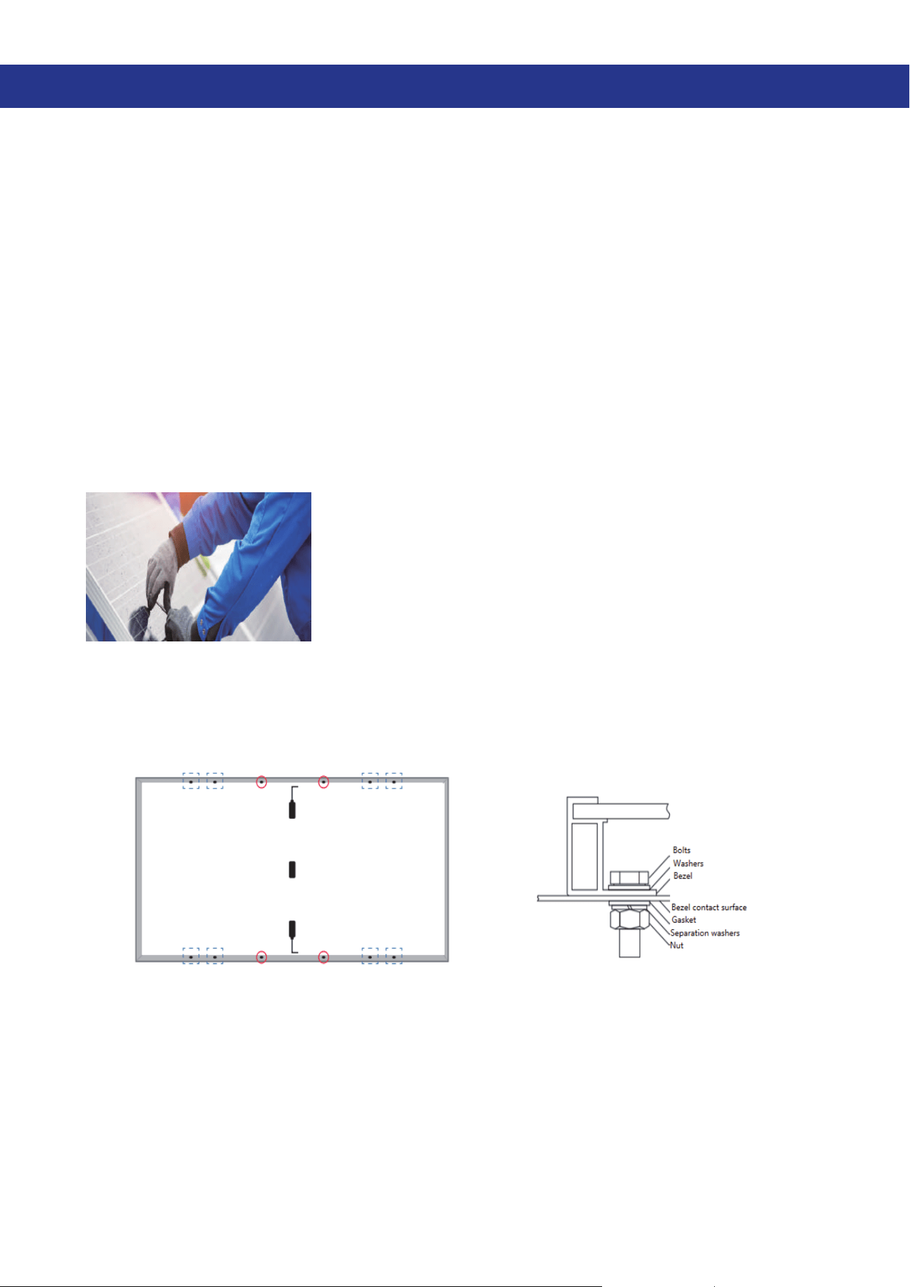
5.2.1. Bolt mounting method
Renogycomponentsareequippedwithcorrespondingmountingholes,thenumber&
correspondingsizearedetailedinthecorrespondingcomponentlayout;currently,theonly
mountingmethodprovidedbyourcompanyisboltmounting.Thecorrespondingbolttype/
sizediagramandthematchingmoduleversionareasfollows.
Figure2Schematicdiagramofsingle-sidedcomponentmountingholes
(Theremainingcomponentmountingholesareshowninthecorrespondingcomponent
layout)
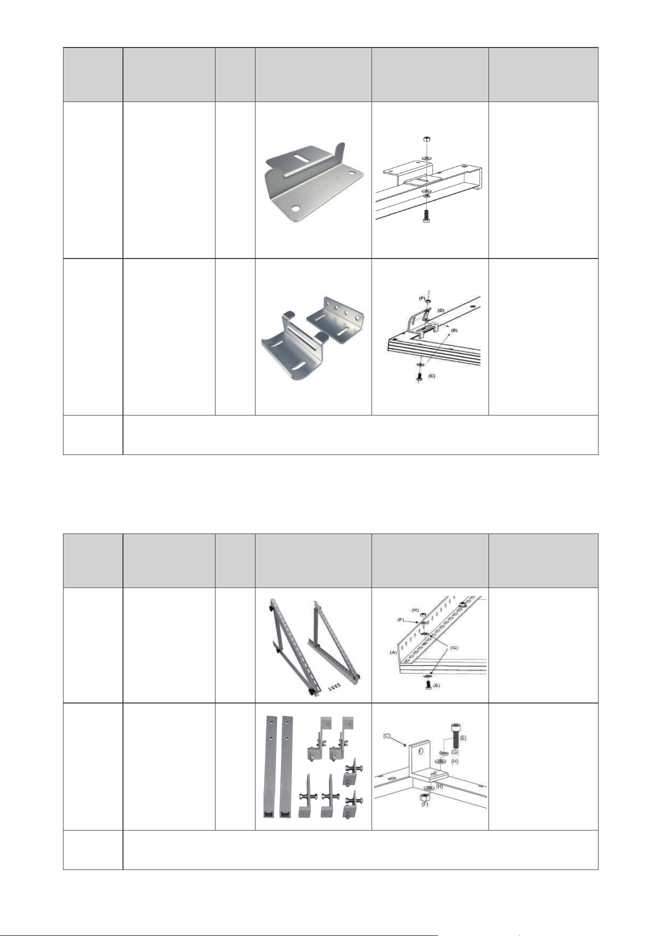
— 11 —
SKU
Number per
set
Bolt
size
Pictures
Installation
schematic
Applicable
component
models
MTS-ZB 4 M6
RSP100D-BK
RNG-100D-SS
RNG-30D-SS
RNG-50D-SS
RNG-175D(Two
setsare
recommended)
RSP-200D(Two
setsare
recommended)
MTS-
ACB
4(Eachset
has2parts)
M6
RSP100D-BK
RNG-100D-SS
RNG-30D-SS
RNG-50D-SS
RNG-175D(Two
setsare
recommended)
RSP-200D(Two
setsare
recommended)
Remarks
Pleasechoosethenumberofboltsandinstallationmethodaccordingtothe
installationenvironment,conditionsandactualsituation.
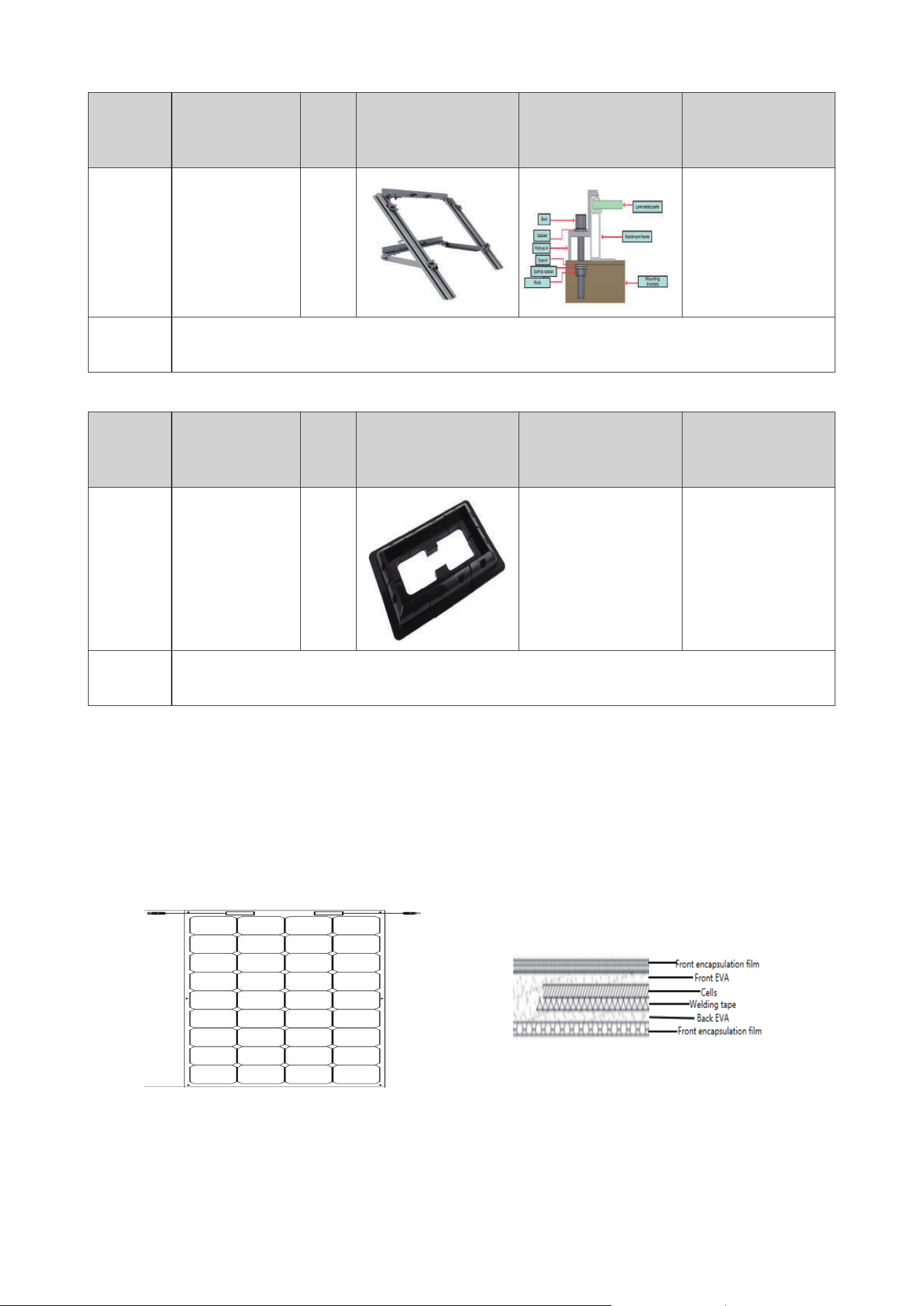
5.2.2. Bolt mounting method with brackets
Renogyalsooersitscustomersanangledmountingbracketthatallowsthecustomer
tofreelyadjusttheangleofthemoduletothelightduringinstallation.Thecorresponding
mountingmethodisalsobolt-on.Themoduleisxedtothebracketbymeansofbolts.
SKU
Number of
matching
solar panels
Bolt
size
Pictures
Installation
schematic
Applicable
component
models
MTS-
TMB
1 Set for 1
panel
M6
RSP100D-BK
RNG-100D-SS
RSP80D-SS
RNG-30D-SS
RNG-50D-SS
MTS-
TM100
1 Set for 1
panel
M8
RSP100D-BK
RNG-100D-SS
RNG-50D-SS
RNG-175D
RSP-200D
RSP450D-120X2
RSP550D-144X2
RNG-320D
Remarks
Pleasechoosethenumberofboltsandinstallationmethodaccordingtothe
installationenvironment,conditionsandactualsituation.
— 12 —
5.2.3. Mounting method of brackets
SKU
Number of
matching
solar panels
Bolt
size
Pictures
Installation
schematic
Applicable
component
models
MTS-
SP100
1 Set for 1
panel
M8
RSP100D-BK
RNG-100D-SS
Remarks
Pleasechoosethenumberofboltsandinstallationmethodaccordingtothe
installationenvironment,conditionsandactualsituation.
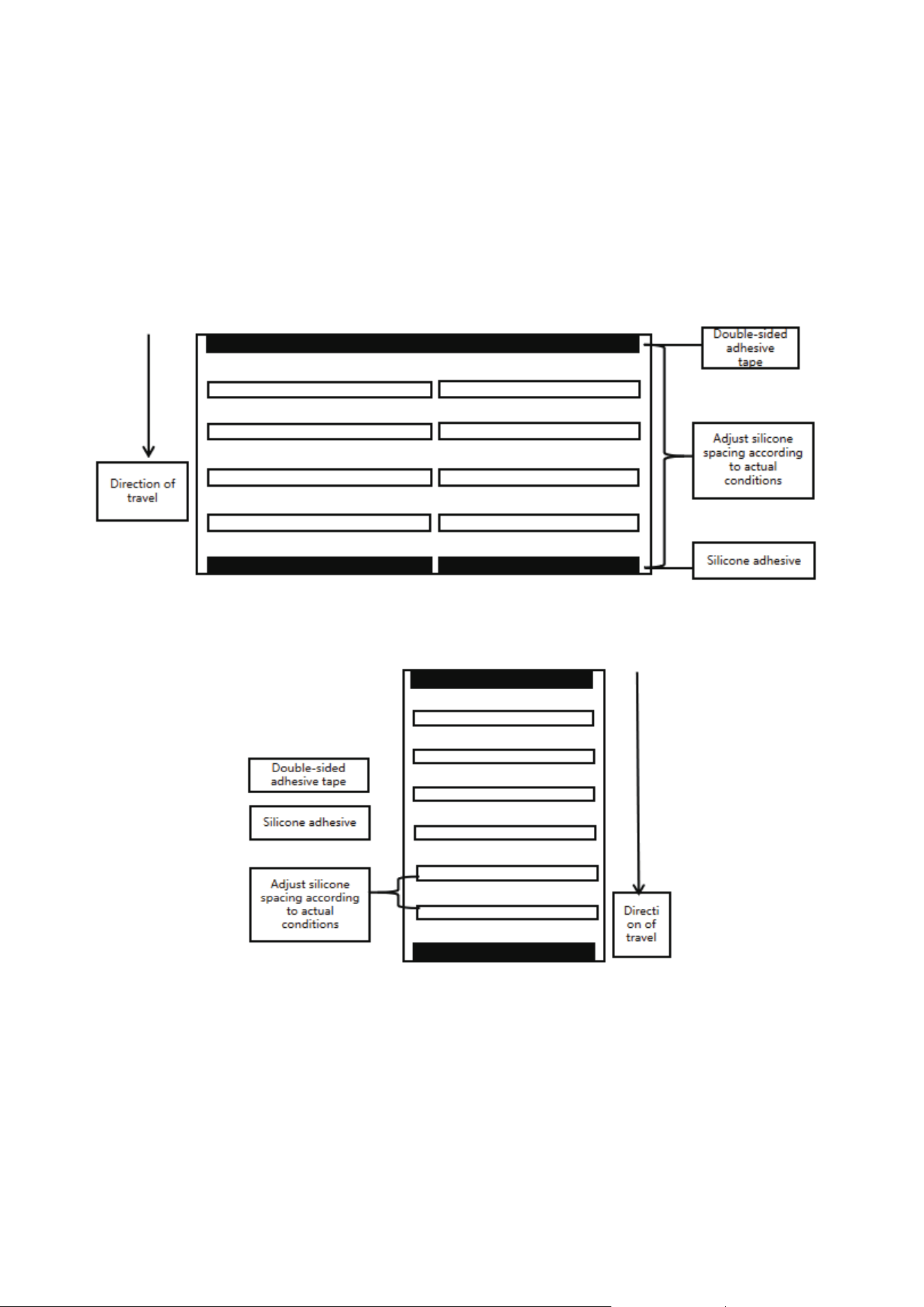
5.2.4. Other installation methods
SKU
Number of
matching
solar panels
Bolt
size
Pictures
Installation
schematic
Applicable
component
models
MTS-CB
1 Set for 1
panel
/ / Allsolarpanels
Remarks
ThismountingmethodrequiresnoadditionaldrillingandissuitableforallRenogy
solarpanels.Themoduleneedstobepre-xedwithsiliconeforinstallation.
5.3.Introductionofexiblemoduleinstallationmethod
Forexiblemodules,Renogyrecommendstheuseofsiliconemountingontheroof.Theroof
shouldbecleanedbeforeinstallationtoensurethatthesurfaceisfreeofdirtandforeign
matter,andthebackofthemoduleshouldbecleanedtoensurethatthebackofthemodule
isfreeofdirtandforeignmatter.Thiswillensureastrongadhesionbetweenthebacksheet
andtheroof.Thesiliconemountingmethodiswidelyusedforexiblemodules,whichfully
combinesthemechanicalpropertiesofexiblemodulesandtoacertainextentavoids
mechanicaldamageduringsubsequentuse.
Figure3Schematicdiagramofthestructureofexiblecomponents
(Therestofthecomponentstructurediagramsarebasedonthecorresponding)
— 13 —
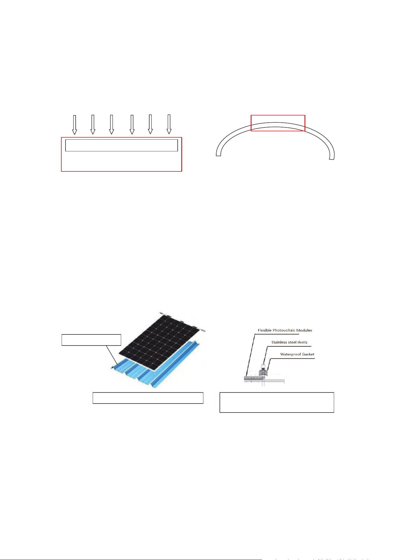
5.3.1.Introductiontoatroofmountingmethods
Aftercleaningthesurfacesofthemodules,stickdouble-sidedtapeoneachshortedgeofthe
componentforxing.Applysiliconealongthecomponenthorizontallywithawidthof6~10mm
andathicknessof3~5mm.Siliconelengthapplicationistobeadjustedaccordingtothelength
ofthecomponent,witharecommendedspacingof10mmbetweenlines.Thespacingallows
forheatdissipationandletswaterrundown.Thecomponentneedstobemountedwithin
5minutestopreventthesiliconefromcuringandaectingthebondingperformance.After
mounting,thecomponentneedstobelightlypressedalongthebondingsurfaceinthesame
directionthesiliconewasappliedusingaprofessionalpressingtool.Thedistancebetweenthe
twocomponentsbeing5~10mm.
Long side facing the direction of travel
Short side facing the direction of travel
Operating notes.
z
Whenapplyingsilicone,itisimportanttonotcompletelysealallfoursidesoftheexible
component,asthiscanaectheatdissipationanddrainage.Renogyrecommendsensuring
thatatleasttheshortedgesarenotsealedtoensureproperheatdissipationanddrainage
andtoavoidtheriskofre.
z
Thenumberofhorizontalsiliconeglueapplicationscanbeadjustedaccordingtopersonal
preference.Renogyrecommendsapplyinggluetotheedgeofthedouble-sidedtapewitha
widthof6-10mmandathicknessof3-5mm.
z
Double-sidedadhesivetapeshouldbeushwiththeedgeasmuchaspossible.
— 14 —
z
Aftertheinstallationiscompleted,itshouldbeleftfor72Htoensurethatthesiliconeisfully
cured,avoidingdirectsunlight,rainandotherharshweatherduringthecuringperiod.
z
Themaximumbendoftheexiblemodulecanreach240°,butthisbendisforthe
convenienceofstorage,theactualinstallationisrecommendedtoinstalltheexible
modulehorizontally,ortheinstallationbendislessthan30°toensurepowergeneration
eciency.
z
Whenashortedgeisusedasthebendingedge,thebendinganglemustnotexceed30°.
Sunlight
Components are fully illuminated Flexible Photovoltaic Modules
Fully sunlit area
PV
Components are fully illuminated
PV
Note:Astheinstallationanglebecomesmorecurved,thenon-illuminatedareaofthemodule
willincrease.Whenthebendingradiusexceeds30degrees,thenon-illuminatedareaofthe
modulewillexceed30%,whichwillaecttheoutputofthemodule.
5.3.2.Introductiontonon-atroofmountingmethods
Aftercleaningtheexiblemodules,stickdouble-sidedtapeoneachlongedgeofthe
componentforxing.Applythesiliconeaccordingtothewidthofthecorrugatedroof
protrusion;installthecomponentwithin5minutesafternishingthesiliconeapplicationto
preventthesiliconefromcuringandaectingthebondingperformance.Useaprofessional
pressingtoolandlightlypressthesurfaceofthecomponentalongthedirectionofgluing.The
distancebetweenthetwocomponentsis5~10mm.
Aftertheinstallationofthesiliconepartiscompleted,theexiblecomponentcanbefurther
xedbyapplyingboltsaccordingtothemountingholesthatcomewiththeexiblecomponent
itself.
Silicone position
Figure 3: Non-flat gluing diagram Figure 4: Schematic diagram of
flexible component mounting holes
Note:Renogyrecommendsthatnon-atroofneedtomeetaminimumof6siliconelineson
thebackside,ifthisconditionisnotmet,theexiblemoduleisnotsuitableforthisroof.
— 15 —
6. Renogy solar panels installation - Electrical installation
6.1. Electrical parameters
Thenominalvaluesofelectricalperformanceparametersforcomponents,suchasIsc,Voc,
andPmax,areobtainedunderstandardtestconditions.Thestandardtestconditionsfor
componentsincludeanirradianceof1000W/m2,celltemperatureof25°C,andairmassAM1.5.
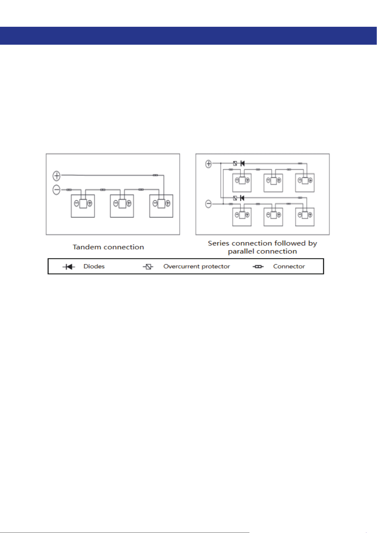
Whencomponentsareconnectedinseries,theVocofthecombinationisthesumoftheVoc
valuesofindividualcomponents,andtheIscremainsthesameasthatofasinglecomponent.
Whencomponentsareconnectedinparallel,theVocisthesameasthatofasingle
component,andtheIscisthesumoftheIscvaluesofmultiplecomponents.Refertothegure
below.Itisnotrecommendedtoconnectcomponentswithdierentparameters,models,or
brandsinseriesorinparallel.
Themaximumnumberofcomponentsthatcanbeconnectedinseriesdependsonthe
maximumsystemvoltagesupportedbythecomponent.Afterbeingconnectedinseriesunder
thelowestlocaltemperatureconditions,theopencircuitvoltagecannotexceedthemaximum
systemvoltagevaluespeciedbythecomponent,suchasDC600V/DC1000V/DC1500V.In
practicalapplications,thenumberofcomponentsconnectedinseriesandparallelneedstobe
designedaccordingtotheparametersandmodelsofthecomponentsandcontrollers.
Theopencircuitvoltagecorrectionfactorcanbecalculatedusingthefollowingformula:
CVoc=1-
β
Voc×(25-T).Tistheexpectedminimumambienttemperatureatthesystem
installationlocation,and
β
(%/°C)isthetemperaturecoecientoftheselectedcomponent
Voc(refertothecorrespondingcomponentparametertable).
Iftheremaybereversecurrentpassingthroughthecomponentthatexceedsthemaximum
fusecurrentofthecomponent,thesamespecicationovercurrentprotectiondevicemustbe
usedtoprotectthecomponent.Ifthenumberofcomponentsconnectedinparallelisgreater
thanorequalto2inaseries,theremustbeanovercurrentprotectiondeviceoneachseries
component,asshowninthegureabove.
6.2. Cable and Wiring
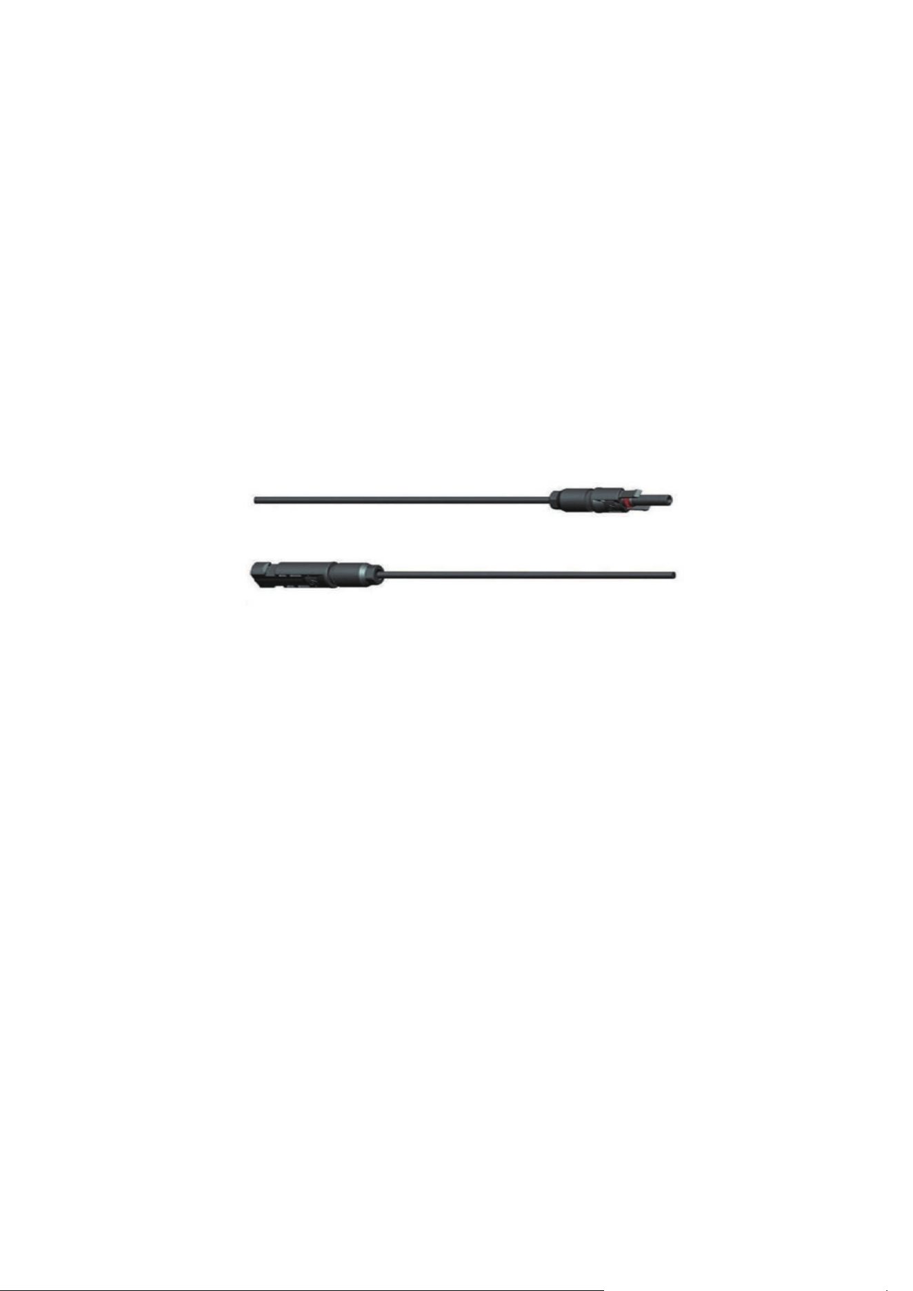
6.2.1 Introduction of cables and connections
Renogymodulesuseajunctionboxwithaprotectionratingforconnections(seemodule
specicationfordetails)toprovidesafeprotectionforthewiringanditscorresponding
connectionsandaccessibleprotectionfornon-insulatedliveparts.Thejunctionboxconsists
ofconnectedcablesandconnectorswithcorrespondingprotectionratings,whichfacilitate
theseries/parallelconnectionofmodules.Eachindividualmodulehastwowiresconnectedto
thejunctionbox,onepositiveandonenegative.Theconnectionofthepositiveandnegative
polesofthemodulescanbeachievedthroughtheMC4connectors.
— 16 —
Specialsolarcablesandappropriateconnectorsshouldbeusedinaccordancewithlocal
re,building,andelectricalregulations(thewiresshouldbecoveredbyaging-resistant
conduits,andifexposedtoair,shouldhaveaging-resistantproperties),andtheelectricaland
mechanicalpropertiesofthecablesshouldbeensured.
Afterthecableisinstalledandconnected,itshouldbeprotectedfrommechanicaldamage.Do
notpressthecabletoohard.Althoughthecableisresistanttoagingandwaterproof,itshould
alsobeprotectedfromdirectsunlightandrain.Theminimumbendingradiusofthecable
shouldbe43mm.
6.2.2 Extension cable selection for component-to-component connection
Renogycurrentlyprovidescustomerswithinter-moduleconnectioncablesmainlyintheform
ofSKU:RNG-EXTCB,withawirediameterspecicationof10/12AWG,andamaximumlengthof
40FTforextensioncables.
6.2.3 Extension cable for connecting the component to the controller
Renogycurrentlyprovidescustomerswithconnectioncablesbetweenmodulesand
controllersmainlyintheformofSKU:RNG-AK,withawirediameterspecicationof10/12AWG,
andamaximumlengthof40FTforextensioncables.
6.3. Connector
Pleasekeeptheconnectorsdryandclean,andensurethatthenutoftheconnectorisina
tightenedstatebeforeconnecting.Donotconnecttheconnectorsiftheyarewet,dirty,orin
anyotherunfavorablecondition.Iftheconnectorsarenotconnectedpositivelyandnegatively,
theydonothavewaterprooffunction.Afterinstallingthemodules,theyneedtobeconnected
assoonaspossibleorappropriatemeasuresneedtobetakentoavoidtheinltrationof
watervaporanddust.Avoiddirectsunlightandimmersioninwaterfortheconnectors.Avoid
theconnectorsfallingonthegroundorontheroof,causingparticlesordusttoenterthe
connectorsandaectingsubsequentuse.Incorrectconnectionsmayproducearcsand
electricshocks.Pleaseensurethatallelectricalconnectionsaresecure.Makesurealllocked
connectorsarefullyconnected.Itisnotrecommendedtousedierenttypesofconnectors
together.
6.4. Bypass Diode
Thesolarcellsinthesolarmoduleareconnectedinserieswithabypassdiodeparallel
protection,whichisencapsulatedinthejunctionbox.Whenahotspotphenomenonoccurs
inamodule,thediodewillstartworkingtopreventthemaincurrentfromowingthroughthe
hotspotcell,therebylimitingtheheatingandperformancelossofthemodule.Notethatthe
bypassdiodeisnotanovercurrentprotectiondevice.Ifthediodeissuspectedorconrmedto
befaulty,pleasecontactRenogy.Itisstrictlyprohibitedtoattempttoopenthejunctionboxof
themoduleonyourown.

— 17 —
7. Renogy solar panels installation - Grounding
Thedesignofthemoduleusesanodized,corrosion-resistantaluminumalloyframesasrigid
support.Inordertoensuresafeuseandpreventdamagefromlightningandstaticelectricity,
themoduleframemustbegrounded.Whengrounding,thegroundingdevicemustbeinfull
contactwiththealuminumalloyinterior,penetratingtheoxidelmonthesurfaceofthe
frame.Itisstrictlyforbiddentoaddanyadditionalgroundingholesonthemoduleframe.The
groundingconductororgroundingwirecanbemadeofcopper,copperalloy,oranyother
materialthatmeetstherequirementsofthecorrespondingnationalelectricalspecicationsas
aconductor.Thegroundingconductormustbeconnectedtotheearththroughanappropriate
groundingelectrode.Theholesmarkedwiththegroundingsymbolontheframecanonlybe
usedforgroundingandnotformoduleinstallation.Formoduleswithoutgroundingholes,they
canbegroundedbyconnectingthemtoagroundedelectricaldevice.
— 18 —
8. Renogy solar panels installation - Operation and maintenance
Itisrequiredtoperformregularinspectionandmaintenanceofthemodules,especiallyduring
thewarrantyperiod.PleasecontactRenogyin2weeksifanyabnormalityordamageisfound.
8.1. Solar panel cleaning
Theaccumulationofforeignsubstances(suchasdustandbirddroppings)ontheglass
surfaceofsolarpanelscanaecttheirpoweroutputandevencausehotspotsinthearea.
Theextentoftheimpactdependsonthetransparencyoftheforeignmaterial.Forexample,a
smallamountofdustontheglasssurfacecanaecttheintensityanduniformityofabsorbed
sunlight,thisusuallydoesnotcausedamagetothesolarpanel,andthepoweroutput
usuallydoesnotdecreasesignicantly.However,alargeamountofdustaccumulation,bird
droppings,andshadingbyplantscanformobstructions,whichcansignicantlyreducepower
outputandevenformhotspots.Itisrecommendedthatthesurfaceofthepanelsshouldnot
beobstructedbyanythingwhenthereissunlight.
Thecleaningfrequencydependsonthehowmuchforeignmatteranddebrisaccumulates.
Inmanyinstancesthefrontsubstrategetscleanedwiththerain,andyoucandecreasethe
cleaningfrequency.Itisrecommendedtowipetheglasssurfacewithwetspongeorsoftcloth.
Pleasedonotcleantheglasswithcleaningagentwhichcontainsacidoralkali.
Toavoidpotentialelectricalshockorburn,pleasecleanthePVpanelsintheearlymorningor
atdusk.DonotcleanthePVpanelswithdamagetotheglasssurface,backboardorwires.
8.2. Visual Inspection of PV Panels
InspectthePVpanelsvisuallytondifthereareappearancedefect,especially:
z
Iftheglassisbroken;
z
Corrosionalongthecells’busbar.Thecorrosioniscausedbymoisturethathasinltrated
intothemoduleswhenthesurfaceencapsulationmaterialdamagedduringtheinstallation
ortransportation.
z
Ifthereisevidenceofburningonthepanel.
z
Checktheencapsulationoftheconnectorwiththecable.
z
EnsurethePVpanelsareuntouchedwithsharpobjects.
z
EnsurethePVpanelsarenotshaded.
z
ChecktheconnectionbetweenthePVpanelsandthemountsandbrackets.
— 19 —
8.3. Inspection of the Connector and the Cable
It’srecommendedtoimplementthefollowingpreventivemaintenanceevery6months:
z
ChecktheconnectionsbetweenthePVpanelsandothero-gridcomponents.
z
Checkthesealinggelofthejunctionboxtoensureifitiscrackorcrevice.
— 20 —
9. Schedule - Renogy solar panel iteration/mix recommendation
SKU Versions Size/mm
Mounting
hole number
& size
Recommended
number of
mounting holes
Mixable
versions
RNG-10D-SS G1 341x266 4-10*7 4 /
RNG-30D-SS G1 570x341 4-10*7 4 /
RNG-50D-SS G1 601x498 4-10*7 4 G1/G2/G3
RNG-50D-SS G2 581x509 4-10*7 4 G1/G2/G3
RNG-50D-SS G3 578x503 4-7*11 4 G1/G2/G3
RNG-80D-SS G1 920x498 20-14*9 4 G1/G2
RNG-80D-SS G2 938x509 20-14*9 4 G1/G2
RNG-100D-SS G1 1074x798 20-14*9 4 G1/G2/G3
RNG-100D-SS G2 1076x509 20-14*9 4 G1/G2/G3
RNG-100D-SS G3 1062x530 20-14*9 4 G1/G2/G3
RNG-100MB G1 1038x533 20-14*9 4 /
RSP100D-BK G1 1100x509 20-14*9 4 G1/G2
RSP100D-BK G2 1062x530 20-14*9 4 G1/G2
RNG-175D G2 1262x699 20-14*9 4 G1/G2
RNG-175D G1 1328x670 20-14*9 4 G1/G2
RSP200D G3 1491x699 20-14*9 4 G1/G2/G3
RSP200D G2 1650x670 20-14*9 4 G1/G2/G3
RSP200D G1 1620x657 20-14*9 4 G1/G2/G3
RNG-320D G1 1665x1002 4-14.5*6.5 4 G1/G2
RNG-320D G2 1665x1002 4-14.5*6.5 4 G1/G2
RSP450D-120 G1 1909x1134 8-14*9 4 /
RSP550D-144 G1 2279x1134
8-14*9;
4-11*7
4 /
RNG-10DB-H G1 481x301
6-Inner
φ
8;Outer
φ
14
6 G1/G2
RNG-10DB-H G2 481x301
6-Inner
φ
8;Outer
φ
14
6 G1/G2
RNG-50DB-H G1 673x508
6-Inner
φ
6;Outer
φ
11
4 G1/G2/G3
RNG-50DB-H G2 683x508
6-Inner
φ
6;Outer
φ
11
4 G1/G2/G3
— 21 —
SKU Versions Size/mm
Mounting
hole number
& size
Recommended
number of
mounting holes
Mixable
versions
RNG-50DB-H G3 712x460
6-Inner
φ
6;Outer
φ
11
4 G1/G2/G3
RNG-100DB-H G1 1219x546
6-Inner
φ
6;Outer
φ
12
6 G1/G2/G3
RNG-100DB-H G2 1219x546
6-Inner
φ
6;Outer
φ
12
6 G1/G2/G3
RNG-100DB-H G3 1093x582
6-Inner
φ
6;Outer
φ
11
6 G1/G2/G3
RSP100DL-36 G1 1093x582
6-Inner
φ
6;Outer
φ
11
6 /
RNG-175DB-H G1 1504x673
6-Inner
φ
6;Outer
φ
12
6 G1/G2
RNG-175DB-H G2 1504x673
6-Inner
φ
6;Outer
φ
12
6 G1/G2
RSP200DB-72 G1 1605x748
6-Inner
φ
6;Outer
φ
11
6 /
RENOGY.COM
Renogy aims to empower people around the world through education and distribution of DIY-friendly renewable
energy solutions.
Renogy Power Plus allows you to stay in the loop with upcoming solar energy innovations, share your experiences
with your solar energy journey, and connect with like-minded people who are changing the world in the Renogy
Power Plus community.
We intend to be a driving force for sustainable living and energy independence.
In support of this eort, our range of solar products makes it possible for you to minimize your carbon footprint
by reducing the need for grid power.
Renogy Empowered
Live Sustainably with Renogy
Did you know? In a given month, a 1kW solar energy system will...
Save 170 pounds of coal from being burned
Save 300 pounds of CO2 from being released into the atmosphere
Save 105 gallons of water from being consumed
@Renogy Solar @Renogy@renogyoicial
Renogy Power
PLUS
Renogy reserves the right to change the contents of this manual without notice.