EN_IMPORTANT, RETAIN FOR FUTURE REFERENCE: READ CAREFULLY.
FR_IMPORTANT:A LIRE ATTENTIVEMENT ET À CONSERVER POUR CONSULTATION
ULTÉRIEURE.
ES_IMPORTANTE, LEA Y GUARDE PARA FUTURAS REFERENCIAS.
PT_IMPORTANTE, RETER PARA REFERÊNCIA FUTURA: LEIA ATENTAMENTE.
DE_WICHTIG! SORGFÄLTIG LESEN UND FÜR SPÄTER NACHSCHLAGEN AUFBEWAHREN.
IT _ IMPORTANTE! CONSERVARE IL PRESENTE MANUALE PER FUTURO RIFERIMENTO E
LEGGERLO ATTENTAMENTE.
US_CAUS_CA
IN221200165V01_US_823-046V80_823-046V81_823-046V82
IN221200165V01_US_823-046V80_823-046V81_823-046V82

1

2
1. Important Safety Instructions
1.1 General Safety Instructions
*The air conditioning is only suitable for indoor use, and is not suitable for other
applications.
*Follow local grid interconnection rules while installing the air conditioning and
ensure that it is properly grounded. If you have any question on electrical
installation, follow the instructions of the manufacturer, and if necessary, ask a
professional electrician to install it.
*Place the machine in a flat and dry place and keep a distance of above 50cm
between the machine and the surrounding objects or walls.
*After the air conditioning is installed, ensure that the power plug is intact and
firmly plugged into the power outlet, and place the power cord orderly to prevent
someone from being tripped or pulling out the plug.
*Do not put any object into the air inlet and outlet of the air conditioning. Keep the
air inlet and outlet free from obstructions.
*When drainage pipes are installed, ensure that the drainage pipes are properly
connected, and are not distorted or bended.
* While adjusting the upper and lower wind-guide strips of the air outlet, pluck it
with hands gently to avoid damaging wind-guide strips.
*When moving the machine, make sure that it is in an upright position.
*The machine should stay away from gasoline, flammable gas, stoves and other
heat sources.
*Don't disassemble, overhaul and modify the machine arbitrarily, otherwise it will
cause a machine malfunction or even bring harm to persons and properties. To
avoid danger, if a machine failure occurs, ask the manufacturer or professionals
to repair it.
*Do not install and use the air conditioning in the bathroom or other humid
environments.
* Do not pull the plug to turn off the machine.
* Do not place cups or other objects on the body to prevent water or other liquids
from spilling into the air conditioning.
*Do not use insecticide sprays or other flammable substances near the air
conditioning.
*Do not wipe or wash the air conditioning with chemical solvents such as
gasoline and alcohol. When you need to clean the air conditioning, you must
disconnect the power supply, and clean it with a half-wet soft cloth. If the
machine is really dirty, scrub with a mild detergent.
*The appliance can be used by children aged from 8 years and above and
persons with reduced physical, sensory or mental capabilities if they have been
given supervision or instruction concerning use of the appliance in a safe way
and understand the hazards involved. Children shall not play with the appliance.
Cleaning and maintenance shall not be made by children without supervision.
*If the supply cord is damaged,it must be replaced by the manufacturer,its
service agent or similarly qualified persons in order to avoid a hazard.
*The appliance shall be stored so as to prevent mechanical damage from
occurring.
*The appliance shall be installed in accordance with national wiring regulations.
*Do not operate your air conditioner in a wet room such as a bathroom or laundry
room.
2.1 Special Safety Instructions for using flammable refrigerant
1. Transport of equipment containing flammable refrigerants
Compliance with the transport regulations
2. Marking of equipment using signs
Compliance with local regulations
3. Disposal of equipment using flammable refrigerants

3
Compliance with national regulations
4. Storage of equipment/appliances
The storage of equipment should be in accordance with the manufacturer's
instructions.
5. Storage of packed (unsold) equipment
Storage package protection should be constructed such that mechanical
damage to the equipment inside the package will not cause a leak of the
refrigerant charge.
The maximum number of pieces of equipment permitted to be stored together
will be determined by local regulations.
6.Information on servicing
6-1 Checks to the area
Prior to beginning work on systems containing flammable refrigerants, safety
checks are necessary to ensure that the risk of ignition is minimised.
For repair to the refrigerating system, the following precautions shall be
complied with prior to conducting work on the system.
6-2 Work procedure
Work shall be undertaken under a controlled procedure so as to minimise the risk
of a flammable gas or vapour being present while the work is being performed.
6-3 General work area
All maintenance staff and others working in the local area shall be instructed on
the nature of work being carried out. Work in confined spaces shall be avoided.
The area around the workspace shall be sectioned off. Ensure that the
conditions within the area have been made safe by control of flammable material.
6-4 Checking for presence of refrigerant
The area shall be checked with an appropriate refrigerant detector prior to and
during work, to ensure the technician is aware of potentially flammable
atmospheres.
Ensure that the leak detection equipment being used is suitable for use with
flammable refrigerants, i.e. non-sparking, adequately sealed or intrinsically safe.
6-5 Presence of fire extinguisher
If any hot work is to be conducted on the refrigeration equipment or any
associated parts, appropriate fire extinguishing equipment shall be available to
hand.
Have a dry powder or CO2 fire extinguisher adjacent to the charging area.
6-6 No ignition sources
No person carrying out work in relation to a refrigeration system which involves
exposing any pipe work that contains or has contained flammable refrigerant
shall use any sources of ignition in such a manner that it may lead to the risk of
fire or explosion.
All possible ignition sources, including cigarette smoking, should be kept
sufficiently far away from the site of installation, repairing, removing and
disposal, during which flammable refrigerant can possibly be released to the
surrounding space.
Prior to work taking place, the area around the equipment is to be surveyed to
make sure that there are no flammable hazards or ignition risks. “No Smoking”
signs shall be displayed.
6-7 Ventilated area
Ensure that the area is in the open or that it is adequately ventilated before
breaking into the system or conducting any hot work.
A degree of ventilation shall continue during the period that the work is carried
out.
The ventilation should safely disperse any released refrigerant and preferably

4
expel it externally into the atmosphere.
6-8 Checks to the refrigeration equipment
Where electrical components are being changed, they shall be fit for the purpose
and to the correct specification.
At all times the manufacturer's maintenance and service guidelines shall be
followed. If in doubt consult the manufacturer's technical department for
assistance.
The following checks shall be applied to installations using flammable
refrigerants:
– The charge size is in accordance with the room size within which the
refrigerant containing parts are installed;
– The ventilation machinery and outlets are operating adequately and are not
obstructed;
– If an indirect refrigerating circuit is being used, the secondary circuit shall be
checked for the presence of refrigerant;
– Marking to the equipment continues to be visible and legible. Markings and
signs that are illegible shall be corrected;
– Refrigeration pipe or components are installed in a position where they are
unlikely to be exposed to any substance which may corrode refrigerant
containing components,unless the components are constructed of materials
which are inherently resistant to being corroded or are suitably protected against
being so corroded.
6-9 Checks to electrical devices
Repair and maintenance to electrical components shall include initial safety
checks and component inspection procedures.
If a fault exists that could compromise safety, then no electrical supply shall be
connected to the circuit until it is satisfactorily dealt with.
If the fault cannot be corrected immediately but it is necessary to continue
operation, an adequate temporary solution shall be used.
This shall be reported to the owner of the equipment so all parties are advised.
Initial safety checks shall include:
- That capacitors are discharged: this shall be done in a safe manner to avoid
possibility of sparking;
- That there no live electrical components and wiring are exposed while
charging, recovering or purging the system;
- That there is continuity of earth bonding.
7.Repairs to sealed components
During repairs to sealed components, all electrical supplies shall be
disconnected from the equipment being worked upon prior to any removal of
sealed covers, etc.
If it is absolutely necessary to have an electrical supply to equipment during
servicing, then a permanently operating form of leak detection shall be located at
the most critical point to warn of a potentially hazardous situation.
Particular attention shall be paid to the following to ensure that by working on
electrical components, the casing is not altered in such a way that the level of
protection is affected.
This shall include damage to cables, excessive number of connections,
terminals not made to original specification, damage to seals, incorrect fitting of
glands, etc.
Ensure that apparatus is mounted securely.
Ensure that seals or sealing materials have not degraded such that they no
longer serve the purpose of preventing the ingress of flammable atmospheres.
Replacement parts shall be in accordance with the manufacturer's
specifications.

5
NOTE:
The use of silicon sealant may inhibit the effectiveness of some types of leak
detection equipment. Intrinsically safe components do not have to be isolated
prior to working on them.
8.Repair to intrinsically safe components
Do not apply any permanent inductive or capacitance loads to the circuit without
ensuring that this will not exceed the permissible voltage and current permitted
for the equipment in use.
Intrinsically safe components are the only types that can be worked on while live
in the presence of a flammable atmosphere. The test apparatus shall be at the
correct rating.
Replace components only with parts specified by the manufacturer.
Other parts may result in the ignition of refrigerant in the atmosphere from a
leak.
9.Cabling
Check that cabling will not be subject to wear, corrosion, excessive pressure,
vibration,sharp edges or any other adverse environmental effects.
The check shall also take into account the effects of aging or continual vibration
from sources such as compressors or fans.
10.Detection of flammable refrigerants
Under no circumstances shall potential sources of ignition be used in the
searching for or detection of refrigerant leaks.
A halide torch (or any other detector using a naked flame) shall not be used.
11. Leak detection methods
The following leak detection methods are deemed acceptable for systems
containing flammable refrigerants:
- Electronic leak detectors shall be used to detect flammable refrigerants, but
the sensitivity may not be adequate, or may need re-calibration. (Detection
equipment shall be calibrated in a refrigerant-free area.)
- Ensure that the detector is not a potential source of ignition and is suitable
for the refrigerant used.
- Leak detection equipment shall be set at a percentage of the LFL of the
refrigerant and shall be calibrated to the refrigerant employed and the
appropriate percentage of gas (25 % maximum) is confirmed.
- Leak detection fluids are suitable for use with most refrigerants but the
use of
detergents containing chlorine shall be avoided as the chlorine may react with
the refrigerant and corrode the copper pipe-work.
- If a leak is suspected, all naked flames shall be removed/ extinguished.
- If a leakage of refrigerant is found which requires brazing, all of the refrigerant
shall be recovered from the system, or isolated (by means of shut off valves) in a
part of the system remote from the leak.
- Oxygen free nitrogen (OFN) shall then be purged through the system both
before and during the brazing process.
12.Removal and evacuation
When breaking into the refrigerant circuit to make repairs – or for any other
purpose – conventional procedures shall be used. However, for flammable
refrigerants it is important that the best practice is followed since flammability is
a consideration. Opening of the refrigeration systems shall not be done by
brazing.
The following procedure shall be adhered to:
- Remove refrigerant;
- Purge the circuit with inert gas;

6
- Evacuate;
- Purge again with inert gas;
- Open the circuit by cutting or brazing.
The refrigerant charge shall be recovered into the correct recovery cylinders.
The system shall be “flushed” with OFN to render the unit safe.
This process may need to be repeated several times.
Compressed air or oxygen shall not be used for this task.
Flushing shall be achieved by breaking the vacuum in the system with OFN and
continuing to fill until the working pressure is achieved, then venting to
atmosphere, and finally pulling down to a vacuum.
This process shall be repeated until no refrigerant is within the system. When
the final OFN charge is used, the system shall be vented down to atmospheric
pressure to enable work to take place.
This operation is absolutely vital if brazing operations on the pipe-work are to
take place.
Ensure that the outlet for the vacuum pump is not close to any ignition sources
and there is ventilation available.
13.Charging procedures
In addition to conventional charging procedures, the following requirements
shall be followed:
– Ensure that contamination of different refrigerants does not occur when using
charging equipment.
– Hoses or lines shall be as short as possible to minimise the amount of
refrigerant contained in them.
– Cylinders shall be kept upright.
– Ensure that the refrigeration system is earthed prior to charging the system
with refrigerant.
– Label the system when charging is complete (if not already).
– Extreme care shall be taken not to overfill the refrigeration system.
Prior to recharging the system it shall be pressure tested with OFN.
The system shall be leak tested on completion of charging but prior to
commissioning.
A follow up leak test shall be carried out prior to leaving the site.
14.Decommissioning
Before carrying out this procedure, it is essential that the technician is
completely familiar with the equipment and all its detail.
It is recommended good practice that all refrigerants are recovered safely.
Prior to the task being carried out, an oil and refrigerant sample shall be taken in
case analysis is required prior to re-use of reclaimed refrigerant. It is essential
that electrical power is available before the task is commenced.
a) Become familiar with the equipment and its operation.
b) Isolate system electrically.
c) Before attempting the procedure ensure that:
– Mechanical handling equipment is available, if required, for handling
refrigerant
cylinders;
– All personal protective equipment is available and being used correctly;
– The recovery process is supervised at all times by a competent person;
– Recovery equipment and cylinders conform to the appropriate standards.
d) Pump down refrigerant system, if possible.
e) If a vacuum is not possible, make a manifold so that refrigerant can be
removed from various parts of the system.
f) Make sure that cylinder is situated on the scales before recovery takes place.

7
g) Start the recovery machine and operate in accordance with manufacturer's
instructions.
h) Do not overfill cylinders. (No more than 80 % volume liquid charge).
i) Do not exceed the maximum working pressure of the cylinder, even
temporarily.
j) When the cylinders have been filled correctly and the process completed, make
sure that the cylinders and the equipment are removed from site promptly and all
isolation valves on the equipment are closed off.
k) Recovered refrigerant shall not be charged into another refrigeration system
unless it has been cleaned and checked.
15. Labelling
Equipment shall be labelled stating that it has been de-commissioned and
emptied of refrigerant.
The label shall be dated and signed.
Ensure that there are labels on the equipment stating the equipment contains
flammable refrigerant.
16. Recovery
When removing refrigerant from a system, either for servicing or
decommissioning, it is recommended good practice that all refrigerants are
removed safely.
When transferring refrigerant into cylinders, ensure that only appropriate
refrigerant
recovery cylinders are employed.
Ensure that the correct number of cylinders for holding the total system charge is
available.
All cylinders to be used are designated for the recovered refrigerant and labelled
for that refrigerant (i.e. special cylinders for the recovery of refrigerant).
Cylinders shall be complete with pressure relief valve and associated shut-off
valves in good working order.
Empty recovery cylinders are evacuated and, if possible, cooled before recovery
occurs.
The recovery equipment shall be in good working order with a set of instructions
concerning the equipment that is at hand and shall be suitable for the recovery of
flammable refrigerants.
In addition, a set of calibrated weighing scales shall be available and in good
working order.
Hoses shall be complete with leak-free disconnect couplings and in good
condition.
Before using the recovery machine, check that it is in satisfactory working order,
has been properly maintained and that any associated electrical components are
sealed to prevent ignition in the event of a refrigerant release.
Consult manufacturer if in doubt.
The recovered refrigerant shall be returned to the refrigerant supplier in the
correct recovery cylinder, and the relevant Waste Transfer Note arranged.
Do not mix refrigerants in recovery units and especially not in cylinders.
If compressors or compressor oils are to be removed, ensure that they have
been evacuated to an acceptable level to make certain that flammable refrigerant
does not remain within the lubricant.
The evacuation process shall be carried out prior to returning the compressor to
the suppliers.
Only electric heating to the compressor body shall be employed to accelerate
this process.
When oil is drained from a system, it shall be carried out safely.

8
This appliance is not intended for use by persons (including children) with
reduced physical, sensory or mental capabilities, or lack of experience and
knowledge, unless they have been given supervision or instruction concerning
use of the appliance by a person responsible for their safety. Children should be
supervised to ensure that they do not play with the appliance.
When moving or relocating the air conditioner,consult experienced service
technicians for disconnection and reinstallation of the unit.
Do not place any other electrical products or household belongings under the
unit.Condensation dripping from the unit might get them wet,and may cause
damage or malfunction of your property.
To keep ventilation openings clear of obstruction.
The appliance shall be stored in a well-ventilated area where the room size
corresponds to the room area as specified for operation.
The appliance shall be stored in a room without continuously operating open
flames (for example:an operating gas appliance )and ignition sources(for
example operating electric heater).
Any person who is involved with working on or breaking into a refrigerant circuit
should hold a current valid certificate from an industry-accredited assessment
authority, which authorises their competence to handle refrigerants safely in
accordance with an industry recognised assessment specification.
Servicing shall only be performed as recommended by the equipment
manufacturer.
Maintenance and repair requiring the assistance of other skilled personnel shall
be carried out by the person competent in the use of flammable refrigerants.
The pipe-work shall be complianced with national gas regulations.
The maximum refrigerant charge amount is 0.45kg.
The installation of pipe-work shall be kept to minimum.
If the refrigerant is flammable the air conditioning equipment shall have red,
Pantone® Matching System (PMS) #185 marked service ports, pipes, hoses, and
other devices through which the refrigerant is serviced. This colour shall be
present at all service ports and where service puncturing or otherwise creating
an opening from the refrigerant circuit to the atmosphere might be expected
(e.g., process tubes). The colour mark shall extend at least 25 mm (1 inch) from
the refrigerant servicing point and shall be replaced if removed

9
Caution, risk of fire
Avertissement : risque
d’incendie/matériaux
inflammables
WARNING
• Do not use means to accelerate the defrosting process or to
clean,other thanthose recommended by the manufacturer.
• The appliance shall be stored in a room without
continuously operating ignition sources (for example: open
flames, an operating gas appliance or an operating electric
heater).
• Do not pierce or burn.
• Be aware that refrigerants may not contain an odour.
AVERTISSEMENT
• Ne pas utiliser de produits permettant d’accélérer le dégel ou
de produits de nettoyage autres que ceux recommandés par
le fabricant.
• L’appareil doit être entreposé dans un endroit sans source
d’allumage
fonctionnant en continu (par exemple : flamme nue, appareil
au gaz en marche ou radiateur électrique en marche).
• Ne pas percer ni brûler.
• Attention : les frigorigènes peuvent être inodores.
1.3 Explanation of symbol displayed on the unit.
Caution, risk of fire
Avertissement : risque
d’incendie/matériaux
inflammables
WARNING
• This symbol shows that this appliance
uses a flammable refrigerant.
• If the flammable refrigerant is leaked
and exposed to an external ignition
source,there is a risk of fire.
CAUTION
• This symbol shows that the operation
manual should be read carefully.
CAUTION
• This symbol shows that a service
personnel should be handling this
equipment with reference to the
installation manual.
CAUTION
• This symbol shows that information is
available such as the operating manual
or installation manual.

10
LCDI POWER CORD AND PLUG
This air conditioner is equipped with an LCDI (Leakage Current Detection and
Interruption) power cord that is required by UL. This power supply cord contains
state-of-the-art electronics that sense leakage current. If the cord is damaged and
leakage occurs, power will be disconnected from the unit.
The test and reset buttons on the LCDI Plug are used to check if the plug is
functioning properly.
WARNING: Test LCDI before each use.
To test the plug:
1. Plug power cord into a grounded 3 prong outlet.
2. Press RESET (on some units a green light will turn on).
3. Press the TEST button, the circuit should trip and cut all power to the air
conditioner(on some units green light may turn off).
4. Press the RESET button for use. You will hear a click and the A/C is ready for
use.
5. The power supply cord must be replaced if it fails to trip when the TEST button
is pressed and the unit fails to reset.
NOTES:
• Do not use this device to turn the unit on or
off.
• Always make sure the reset button is
pushed in for correct operation
WARNING:
• The power supply cord must be replaced if
it fails to reset when either the test button is
pushed, or it cannot be reset.
• If power supply cord is damaged, it cannot
be repaired.
• It must be replaced by one obtained from
the product manufacturer.
WARNING – RISK OF FIRE
It is important the plug fits tightly into the wall outlet.
If the plug does not fit securely and appears loose, it should not be used.
Have a licensed electrician replace the receptacle.
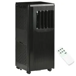
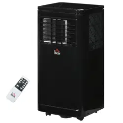
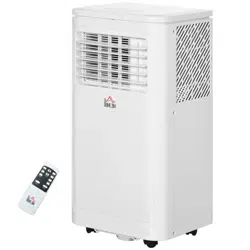
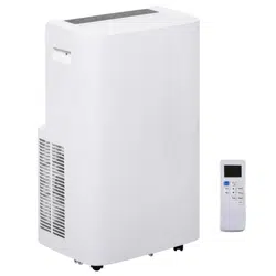
II.Features and Components
1:Features
*Brand new appearance, compact structure, smooth line, simple and generous
shape.
*Functions of refrigeration, dehumidification, air supply and continuous drainage
*Outdoor interface is set high to facility assembly and keep the smooth flow of the
heat pipe.
*LED displays the control panel, beautiful and fashionable, with high-quality
remote control.It adopts a user-friendly remote control design.
*Air filtration capability.
*Timing switch function.
*Protection function of automatically restarting the compressor after three minutes,
a variety of other protection functions.
T h e M a x o p e r a t i o n t e m p e r a t u r e f o r t h e a i r c o n d i t i o n e r C o o l i n g :
35/24℃(95℉/76℉); Temperature operation range: 7-35℃ (45℉/95℉).

11
2.Components

12
Assemble the connector:
Insert the window slider connector into the hole and push the connector left to fix it
onto the kit.
Then lock the connector by supplied screw.
III. Control Setting
1.Control panel operation instructions
1)operation interface:
1. Power Key
2. Mode Key 3.Time Key 4.Down Key 5.Up Key
6.Speed Key 7.Sleep Key 8. Low speed 9. High speed 10.Display
11.Cooling 12.Fan 13.Dehumidify 14.Water Full

13
1: When the machine is plug on for the first time, the buzzer will shout, and the
machine will get into standby status.
2: Power Key: press the key to turn on and turn off the machine. In the case of
power on, press the key to turn off the machine; in the case of power off, press the
key to turn on the machine.
3: Mode Selection Key: In the case of power on, press the key to switch between
cooling → fan → dehumidifying mode.
4: Up Key and Down Key: press the two keys to change the setting temperature
or setting time, operate as follows:
While setting temperature, press up key or down key to select the required
temperature (not available in fan or dehumidifying mode).
While setting time, press up key or down key to select the required time.
5: Wind Speed Selection Key:
1£© In cooling and fan mode, press the key to select high,low wind speed
operation. But limited by
anti-cold conditions, under certain conditions, it may not run according to the set
wind speed.
2£© In dehumidifying mode, pressing the key is invalid, and the fan will forcibly
choose low wind speed operation.
6: Timing Key:
In the case of power on, press the key to close timing; in the case of power off,
press the key to open timing.
Press the key, when the timing symbol flashes, press up and down key to select the
required timing value.
Timing values can be set in 1-24 hours and the timing value is adjusted up or down
by one hour.
7: Sleep Mode:
In the cooling Mode,Press the Sleep Key to turn on the sleep mode,then the unit will
work on Energy-Saving and quiet type.
8: Information on the WIFI App “Smart Life - Smart Living”
The Smart Life - Smart Living app is available for android and iOS.Scan the
corresponding QR code to get directly to the download.
NOTE:
Depending on the provider, there may be costs involved in downloading the app.
Google Play App Store

14
Information on How to Use the App
This appliance allows you to operate the appliance via your home net-work.
A prerequisite is a permanent Wi-Fi connection to your router and the free app
“Smart Life - Smart Living”.
You can easily access all functions of the appliance via the app. Since the app
constantly improved, we cannot provide a more detailed description here.
We recommend disconnecting the appliance from the power supply when you are
away from home to prevent unintentional switching on while you are on the road!
System Requirement for Use of the App
iOs 8.0 or higher
Android 4.4 or higher
Commissioning via the App
1. Install the “Smart Life - Smart Living” app. Create a user account. 2. Activate the
Wi-Fi function in the settings of your appliance.
3. Place the air-conditioning appliance within a distance of around 5 meters of your
router.
4. The device can be added when the air conditioner is in standby mode,
the indicator Wifi (sleep) on the control panel will blink quickly. To do so, press and
hold
down the SPEED button for approx. 5 seconds. If the indicator blinks slowly, repeat
the operation.
5. Launch the app and select “+”.
6. Select the “air conditioner” menu and follow the instructions on the display.
7. The correct connection of the air conditioner to the app is signalled by the
constant illumination of the indicator Power. Now you can operate the appliance
using the app.
NOTE:
The appliance can only be operated with 2.4 GHz routers. 5 GHz routers are
not supported.
The appliance is equipped with only one network connection. It can not be
turned off.
NOTE:
The appliance can only be operated with 2.4 GHz
routers. 5 GHz routers are not supported.
The appliance is equipped with only one network
connection. It can not be turned off.
2.operation instructions of remote control
1) The remote control Panel is as follows:

15
Instructions of key operation of the high-quality remote control are as
follows:
1.Power: Press+++ the key to turn on or turn off the machine.
2.Timer: press+++ the key to set timing.
3. Down: press+++the key to reduce temperature and timing set value.
4. Mode: press+++ the key to switch between cooling, fan, dehumidifying
mode.
5. Up: press+++ the key to increase temperature and timing set value.
6. Fan: press+++ the key to select high, low wind speed.
7. Sleep Mode: Press +++the key to turn on the sleep mode.
IV. Protection function
3.1、Frost Protection Function:
In cooling, dehumidifying or economic power saving mode, if the
temperature of the exhaust pipe is too low, the machine will automatically
enter protection status; if the temperature of the exhaust pipe rises to a
certain temperature, it can automatically revert to normal operation.
3.2、Overflow Protection Function:
When water in the water pan exceeds the warning level, the machine will
automatically sound an alarm, and the "FULL" indicator light will flash. At this
point, you need to move the drainage pipe connecting the machine or the
water outlet to sewer or other drainage area to empty the water (details see
Drainage Instructions at the end of this chapter). After the water is emptied,
the machine will automatically return to the original state.
3.3、Protection Function of the Compressor
To increase the service life of the compressor, it has a 3-minute delay booting
protection function after the compressor is turned off.
V.Installation and adjustment
1.Installation:
Warning: before using the mobile air conditioning, keep it upright for at least
two hours.
The air conditioning can be easily moved in the room. In the moving process,
ensure that the air conditioning is in the upright position and the air
conditioning should be placed on a flat surface. Do not install and use the air
conditioning in the bathroom or other humid environments.
1.1 Install the heat pipe assembly (as shown in Fig.1)

16
Figure 1
1)take out the outer connector assembly and the exhaust pipe assembly, and
remove the plastic bags;
2)insert the heat pipe assembly (the end of the exhaust joint) into the back panel
vent slot (push to the left) and complete the assembly (as shown in figure 1).
1.2 Installation of window sealing plate components
1.Half open the window,and mount the window sealing plate assembly to the
window (as shown in Fig.2 and Fig.3).Components can be placed in horizontal and
vertical direction.
2.Pull various components of the window sealing plate assembly open, adjust their
opening distance to bring both ends of the assembly into contact with the window
frame, and fix various components of the assembly.1.2 Install the window sealing
plate assembly
Notes:1)the flat end of the exhaust pipe joints must be snapped into place.
2)The pipe cannot be distorted nor has substantial turning (greater than 45 °). Keep
the ventilation of the exhaust pipe not blocked.

17
Figure 2 Figure 3
1.3 Install the body
1)Move the machine with installed heat pipe and fittings before the window,
and the distance between the body
and walls or other objects shall be least 50 cm (as shown in Fig.4).
Figure4
3)Elongate the exhaust pipe and snap the flat end of the exhaust pipe joints into the
hole of the window sealing
plate assembly (as shown in Fig.5 and Fig.6) .
Notes:1、the flat end of the exhaust pipe joints must be snapped into place.
2、The pipe cannot be distorted nor has substantial turning (greater than 45 °).
Keep the ventilation of the exhaust pipe not blocked.

18
Figure 5 Figure 6
Important Notice:
The length of the exhaust hose shall be 280~1,500mm, and this length is based on
the specifications of the air conditioning. Do not use extension tubes or replace it
with other different hoses, or this may cause a malfunction. Exhaust host must be
not blocked; otherwise it may cause overheating.
VI. Drainage Instructions
This machine has two drainage methods: manual drainage and continuous
drainage.
1.Manual drainage:
1) When the machine stops after the water is full, turn off the machine power and
unplug the power plug.
Notes:Please move the machine carefully, so as not to spill the water in the water
pan at the bottom of the
body.
2) Place the water container below the side water outlet behind the body.
3)Unscrew the drainage cover and unplug the water plug, the water will
automatically flow into the water container.

19
Notes:1)Keep the drainage cover and the water plug properly.
2)During drainage, the body can be tilted slightly backwards.
3)If the water container cannot hold all the water, before the water container is full,
stuff the water outlet
with the water plug as soon as possible to prevent water from flowing to the floor or
the carpet.
4)When the water is discharged, stuff the water plug, and tighten the drainage cove

20
Continuous drainage (Optional) (only applicable to dehumidifying mode), as shown
in figure:
1) Unscrew the drainage cover, and unplug the water plug.
2) Set the drainage pipe into the water outlet.
3) Connect the drainage pipe to the bucket.

21
VII. Maintenance
Cleaning: before cleaning and maintenance, turn off the machine and unplug the
plug.
1.Clean the surface
Clean with surface of machine with a wet soft cloth. Don't use chemicals, such as
benzene, alcohol, gasoline, etc; otherwise, the surface of the air conditioning will
be damaged or even the whole machine will bedamaged.
2.Clean the filter screen
If the filter screen is clogged with dust, and the effectiveness of the air
conditioning is reduced, be sure to clean the filter screen once every two
weeks.
Clean the upper filter screen frame
1)Unscrew one screw fixed by EVA filter net and back shell with screwdriver, and
take out EVA filter net.
2)Put the EVA filter screen into warm water with neutral detergent (about 40℃ /
104℉) and dry it in the shade after rinsing clean.

22
VIII. Unit Storage:
1:Unscrew the drainage cover, unplug the water plug, and discharge the water in
the water pan into other water
containers or directly tilt the body to discharge the water into other containers.
2:Turn on the machine, adjust it to low-wind ventilation mode, and maintain this
state until the drainage pipe becomes
dry, so as to keep the inside of the body in a dry state and prevent it from mildewing.
3:Turn off the machine, unplug the power plug, and wrap the power cord around the
wrapping post; install the water plug and the drainage cover.
4:Remove the exhaust pipe and keep it properly.
5:Cover the air conditioning with a plastic bag. Put the air conditioning in a dry
place, keep it out of the reach of children, and take dust control measures.
6:Remove batteries of the remote control and keep them properly.
Note: ensure that the body is placed in a dry place and keep all machine
components properly.

23
IX. Troubleshooting
Do not repair or disassemble the air conditioning by yourself. Unqualified repair will
lead to failure of the
warranty card, and may cause damage to users or their properties.
Problems Reasons Solutions
The air
conditioning does
not work.
There is no electricity.
Turn it on after connecting it to a socket with
electricity.
The overflow indicator displays "FL". Discharge the water inside.
The ambient temperature is too low or
too high
Recommend to use the machine in at the
temperature of 7-35 ℃ (45-95 ℉).
In cooling mode, the room temperature
is lower than the set temperature; in
heating mode, the room temperature is
higher than the set temperature.
Change the set temperature.
In dehumidification mode, the ambient
temperature is low.
The machine is placed in a room with an
ambient temperature of greater than 17 ℃ (62
℉).
The cooling effect
is not good
There is direct sunlight. Pull the Curtain.
Doors or windows are open; there are a
lot of people; or in cooling mode, there
are other sources of heat.
Close doors and windows, and add new air
conditioning.
The filter screen is dirty. Clean or replace the filter screen.
The air inlet or outlet is blocked. Clear obstructions.
Big Noise
The air conditioning is not placed on a
flat surface.
Put the air conditioning on a flat and hard place
(to reduce noise).
compressor does
not work.
Overheat protection starts.
Wait for 3 minutes until the temperature is
lowered, and then restart the machine.
The remote
control does not
work.
The distance between the machine and
the remote control is too far.
Let the remote control get close to the air
conditioning, and make sure that the remote
control directly faces to the direction of the
remote control receiver.
The remote control is not aligned with
the direction of the remote control
receiver.
Batteries are dead. Replace batteries.
Displays 'E1'. The room temperature sensor is
abnormal.
Check the pipe temperature sensor and related
circuitry.
Displays 'E2' The pipe temperature sensor is
abnormal.
Check the room temperature sensor and related
circuitry.
Note: If problems not listed in the table occur or recommended solutions do not
work, please contact the
professional service organization.
X. Addendum
Fuse Parameters
Type: 5H or 5TE or 932 or 524
Voltage: 250V
Current: 3.15A

24
Schematic Diagram

25