Loading ...
Loading ...
Loading ...
5English
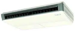
12 or more
Air inlet
Air outlet
Obstruction
Floor
Required service
space
(Length : in.)
1 3/16 or more 1 3/16 or more
∗∗
Where pipe between indoor and outdoor units is possible •
within the allowable limit.
(Refer to the installation manual for the outdoor unit.)
Install the indoor and outdoor units, power wire and •
connecting wires at least 3.5 ft. away from televisions or
radios in order to prevent image interference or noise.
(Depending on the radio waves, a distance of 3.5 ft. may
not be suffi cient enough to eliminate the noise.)
Use suspension bolts for installation. Check whether (2)
the ceiling is strong enough to support the weight of
the unit or not. If there is a risk, reinforce the ceiling
before installing the unit.
(Installation pitch is marked on the paper pattern for instal-
lation. Refer to it to check for points requiring reinforcing.)
This product may be installed on ceilings up to 10.6 ft. (3)
from the fl oor.
A direction of installation.(4)
Refrigerant piping : the rear side, right side or upper part. •
Wiring : only the rear side. •
Drain piping : the rear right side or the right side. •
(As the rear left, installation is impossible.)
PREPARATIONS BEFORE INSTALLATION4.
Relation of holes for indoor unit, suspension bolt posi-(1)
tion, piping and wiring.
3 3/4
6 1/4
26 1/8
Conduit
hole
Front view
62 5/8 (Indoor unit)
61 (Suspension bolt pitch)
7 1/4
6 1/4
8 1/4
10 1/4
(Suspension
bolt pitch)
26 3/4 (Indoor unit)
27 3/16
24 5/8
Top liquid pipe hole
Top gas pipe hole
Suspension bolt (× 4)
Air outlet
False ceiling view
(length : in.)
Wiring hole
Drain pipe hole
Rear side pipe hole
22
25 3/4
27 11/16
5 5/8
6
Make holes for suspension bolts, refrigerant and drain (2)
pipe, and wire.
Refer to the paper pattern for installation. •
Select the location for each of holes and open the holes in •
the ceiling.
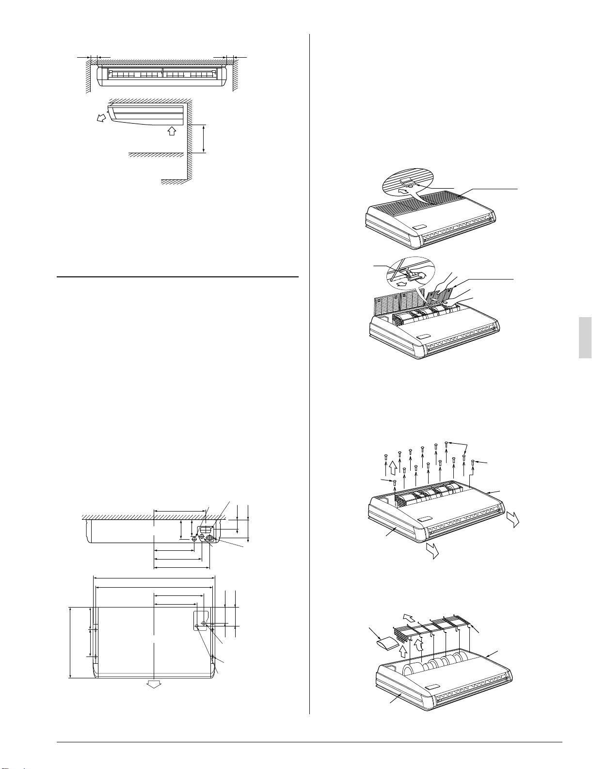
Remove the parts from the indoor unit.(3)
Detach the suction grille.
(3-1)
Slide the locking knobs (×2) on the suction grille inward •
(direction of arrows) and lift upwards. (Refer to Fig. 1)
With the suction grille open, remove the suction grille for- •
ward, holding on to the rear tabs (×2) on the suction grille.
(Refer to Fig. 2)
Fig. 1
Knob
Suction grille
Fig. 2
Suction grille
Tab
Remove the decoration panels (left and right) and the pro-
(3-2)
tection net.
After removing the securing screws for the decoration •
panels (one each), pull them forward (in the direction of
the arrow) and remove them. (Refer to Fig. 3)
Remove the securing screws for the protection net. •
(Refer to Fig. 3)
Decoration panel
securing screw
(M4)
Decoration panel
Fig. 3
Protection net
securing screws (M4)
Decoration
panel
Decoration panel
securing screws (M4)
Raise one side of the protection net upwards (in the direc- •
tion of the arrow (i)) and remove back (the arrow (ii)).
(Refer to Fig. 4, 5)
Take out the accessories. •
Decoration panel
Decoration
panel
Accessories
Fig. 4
Protection net
(ii)
(i)
3PN0624012MEN.indd53PN0624012MEN.indd5 2008/12/2613:22:522008/12/2613:22:52
Loading ...
Loading ...
Loading ...