
Loading ...
Loading ...
Loading ...
11English
L 1
POWER SUPPLY
L 2
power supply
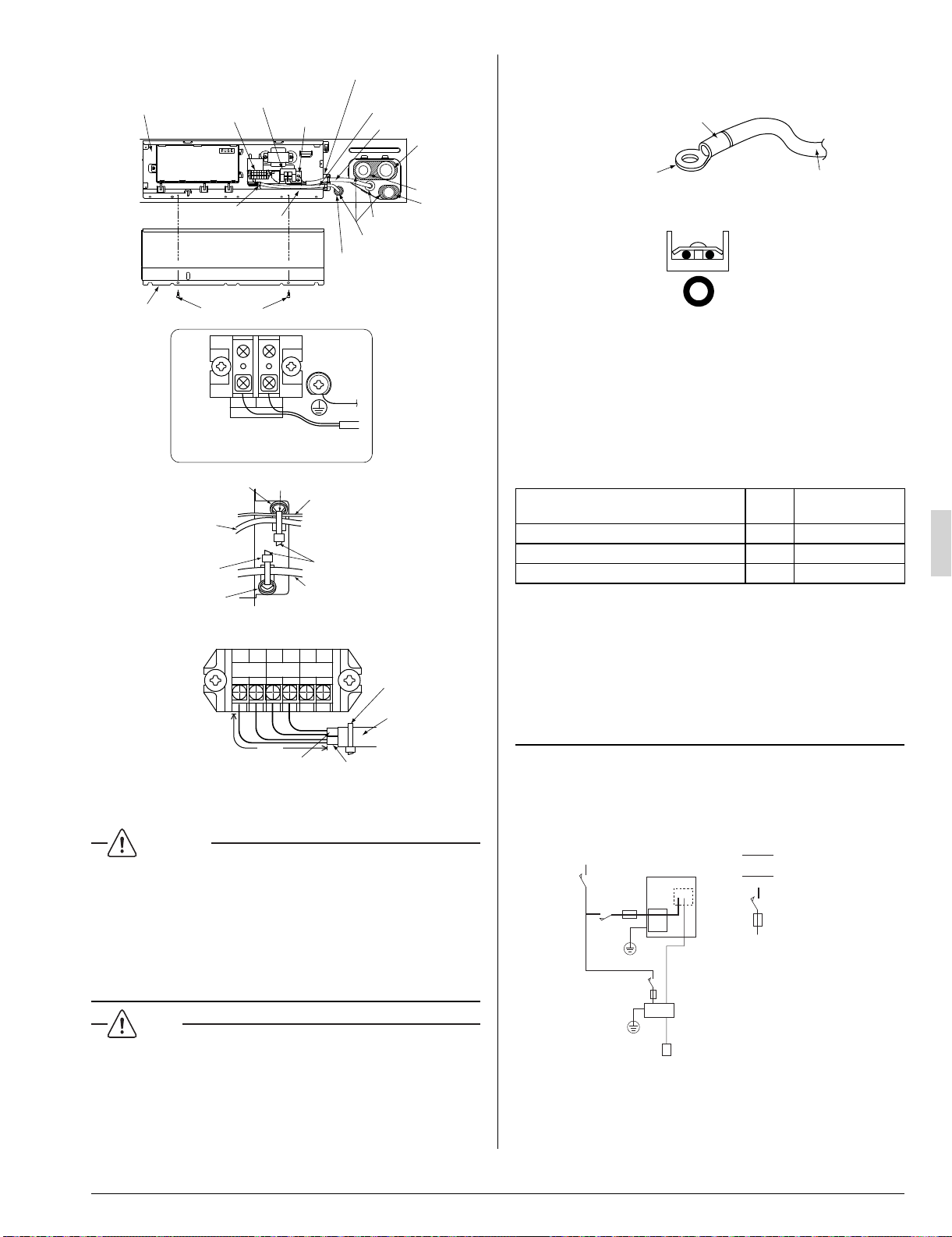
How to connect power supply
terminal block (2P)
Control box
Transmission
terminal block (6P)
Power supply
teminal block (2P)
Remote controller wire
and transmission wire
Refer to Fig. 27
Ground terminal
Power supply wire
Gas pipe
Liquid pipe
Drain pipe
Conduit
Corking or Putty
Resin bush (10)
Control box
lid secuing screw (2pcs.)
Control box lid
Insulating tube (11)
Clamp (4)
Fig. 26
Fastener
Clamp (4)
Clamp (4)
Ground wire
After securing the
cramp material
to the bracket,
cut off any extra
material.
Remote controller wire and
transmission wire
Fastener
Power supply wire
Fig. 27
P1 P2 F1 F2 T1 T2
REMOTE
CNTRL
FORCED
OFF
TRANSMISSION
WIRING
Clamp (4)
Remote controller wire
Transmission
terminal block (6P)
Transmission wire
Insulating
tube (11)
1 in.
Fig. 28
In the insulating tube (11), it can let the remote controller wire •
and transmission wire pass to 2.
WARNING
Never connect power supply wiring to the terminal block for •
remote controller wiring as this could damage the entire system.
Use only specifi ed wire and connect wires to the terminal •
tightly. Be careful wires do not place external stress on ter-
minals. Keep wires in neat order so as to not obstruct other
equipment. Make sure that the electric box lid fi ts tightly.
Incomplete connections could result in overheating and, in
worse case, result in electric shock or fi re.
NOTE
1. Use round crimp-style terminals for connecting wires to the
power supply terminal block.
If unavailable, observe the following points when wiring.
Do not connect wires of different gauge to the same •
power supply terminal.
(Looseness in the connection may cause overheating.)
Use the specifi ed electric wire. Connect the wire securely to •
the terminal. Lock the wire down without applying excessive
force to the terminal. (Tightening torque: 0.97 ft lbf ±10%)
Electric wire
Round crimp-style terminal
Attach insulation sleeve
Connect wires of the
same gauge to both side.
2. Tightening torque for the terminal screws.
Use the correct screwdriver for tightening the terminal •
screws. If the blade of screwdriver is too small, the head
of the screw might be damaged, and the screw will not be
properly tightened.
If the terminal screws are tightened too hard, screws •
might be damaged.
Refer to the table below for the tightening torque of the •
terminal screws.
Table 4
Terminal Size
Tightening torque
(ft-lbf)
Transmission terminal block (6P) M3.5 0.58 – 0.72
Power supply terminal block (2P) M4 0.87 – 1.06
Ground terminal M4 0.87 – 1.06
3. Do not connect wires of different gauge to the same ground
terminal. Looseness in the connection may deteriorate pro-
tection.
4. Outside of the unit, keep transmission wire at least 5 in.
away from power supply wire. The equipment may malfunc-
tion if subjected to electrical (external) noise.
5. For remote controller wire, refer to the “INSTALLATION
MANUAL OF REMOTE CONTROLLER” attached to the
remote controller.
WIRING EXAMPLE 9-2
Fit the power supply wire of each unit with a switch and fuse •
as shown in the drawing.
COMPLETE SYSTEM EXAMPLE
Power supply wire
Transmission wire
Switch
Fuse
Power supply
Main
switch
Remote controller
Indoor unit
Outdoor unit
3PN0624012MEN.indd113PN0624012MEN.indd11 2008/12/2613:22:542008/12/2613:22:54
Loading ...
Loading ...
Loading ...