Loading ...
Loading ...
Loading ...
13English
2 remote controllers control11-2
(Controlling 1 indoor unit by 2 remote controllers)
When using 2 remote controllers, one must be set to “MAIN” •
and the other to “SUB”.
MAIN/SUB CHANGEOVER
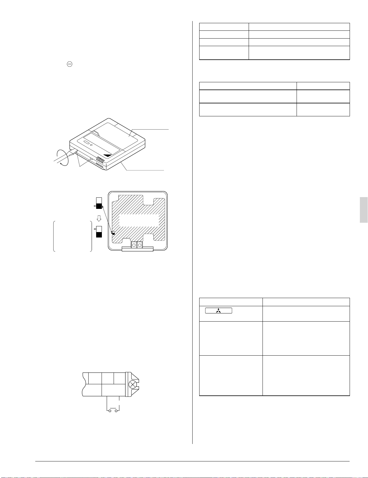
(1) Insert a
screw driver into the recess between the up-
per and lower part of remote controller and, working from
the 2 positions, pry off the upper part.
The remote controller PC board is attached to the upper
part of remote controller. (Refer to Fig. 30)
(2) Turn the MAIN/SUB changeover switch on one of the 2
remote controllers PC boards to “S”. (Leave the switch of
the other remote controllers set to “M”.) (Refer to Fig. 31)
Upper part of
remote controller
Lower part of
remote controller
Insert the screw driver
here and gently work
off the upper part of
remote controller.
Fig. 30
S
M
S
S
M
Remote controller
PC board
(Factory setting)
Only 1 remote
controller needs
to be changed if
factory settings
have remained
untouched.
Fig. 31
Wiring Method
(See “8. ELECTRIC WIRING WORK” and “9. WIRING EXAM-
PLE AND HOW TO SET THE REMOTE CONTROLLER” on
page from 10 to 12.)
(3) Remove the control box lid.
(4) Add 2nd remote controller to the transmission terminal
block (P1, P2) in the control box. (There is no polarity.)
(Refer to Fig. 28 on page 11 and Table 4 on page 11)
COMPUTERISED CONTROL 11-3
(FORCED OFF AND ON/OFF OPERATION)
See “FIELD SETTING” on page 12 for local settings.
(1) Wire specifi cations and how to perform wiring
Connect the input from outside to terminals T1 and T2 of
the transmission terminal block.
F2 T1 T2
FORCED
OFF
Input A
Wire specifi cation Sheathed vinyl wire or cable (2 wires)
Gauge AWG 18-16
Length Max. 328 ft.
External terminal
Contact that can ensure the minimum appli-
cable load of 15 V DC, 10 mA.
(2) Actuation
The following table explains FORCED OFF and ON/OFF •
OPERATIONS in response to Input A.
FORCED OFF ON/OFF OPERATION
Input “ON” stops operation (impossible by
remote controllers.)
Input OFF
→
ON turns
ON unit.
Input OFF enables control by remote con-
troller.
Input ON
→
OFF turns
OFF unit.
(3) How to select FORCED OFF and ON/OFF OPERATION
Turn the power on and then use the remote controller to •
select operation.
CENTRALIZED CONTROL11-4
For centralized control, it is necessary to designate the group •
No. For details, refer to the manual of each optional control-
lers for centralized control.
TEST OPERATION 12.
Refer to the section of “FOR THE FOLLOWING ITEMS,
TAKE SPECIAL CARE DURING CONSTRUCTION AND
CHECK AFTER INSTALLATION IS FINISHED.” on page 4.
Make sure if the service lids are closed on the indoor and out- •
door units.
After fi nishing the construction of refrigerant pipe, drain pipe •
and electric wire, conduct the check operation referring to the
installation manual of the outdoor unit.
The operation lamp of the remote controller will fl ash when a •
malfunction occurs. Check the malfunction code on the liquid
crystal display to identify the point of trouble. An explanation
of malfunction codes and the corresponding trouble is pro-
vided in the installation manual of the outdoor unit.
It any of the items in Table 6 are displayed, there may be a
problem with the wiring or power, so check the wiring again.
Table 6
Remote control display Content
“
” (under
centralized control) is lit up
There is a short circuit at the •
FORCED OFF terminals (T1, T2)
“U4” is lit up
“UF” is lit up
The power on the outdoor unit is off. •
The outdoor unit has not been wired •
for power supply.
Incorrect wiring for the transmission •
wiring and / or FORCED OFF wiring.
The transmission wiring is cut. •
No display
The power on the indoor unit is off.•
The indoor unit has not been wired •
for power supply.
Incorrect wiring for the remote con-•
troller wiring, the transmission wiring
and / or the FORCED OFF wiring.
The remote controller wiring is cut.•
If “U3” is lit up, the malfunction code shows the check opera- •
tion has not been performed yet.
HOW TO DIAGNOSE FOR MALFUNCTION12-1
With the power on, it is possible to monitor the type of mal-
function by looking at the malfunction code displayed in
the remote controller.
3PN0624012MEN.indd133PN0624012MEN.indd13 2008/12/2613:22:542008/12/2613:22:54
Loading ...
Loading ...
Loading ...