Loading ...
Loading ...
Loading ...
3. Loosenarmlockknobuntilarmisfreetomove.
Note:In accordance with the UL standard, stops have
been provided to prevent 360 ° rotation of the radial
arm.
Loosen carriage lock knob and position arm against
stop {approximately 50 ° Miter) and carriage directly
over the center of left hand channel.
4. Slide the arbor wrench handle between end of motor
shaft and mounting channel to achieve an accurate
measurement. Carefully lower the motor with elevation
crank until the end of shaft is just touching the arbor
wrench. The wrench should slide back and forth with
only slight resistance. Tighten screw "A".
!
L..... ._ 0_fj SCRE,,''A .-''z"
I . ARBOR _,','REN C H
/ /
NOTE: Do not change this elevation setting until both
left and right hand table support channels have been
adjusted.
5. Move arm and carriage to screw "B" and tighten
support in the same manner.
6. Move arm and carriage to right hand support channel
and level in the same manner you adjusted the left hand
support channel.
7. Recheck both support channels to make sure that
tightening screws did not affect the accuracy of the
adjustment.
8. Elevate saw and place motor in vertical position to
provide clearance for installation of front (work) table.
/
\, ARBOR WRENCH
\
TABLE MOLINT ING
SUPPORT CHANNEL
(LEFT HAND)
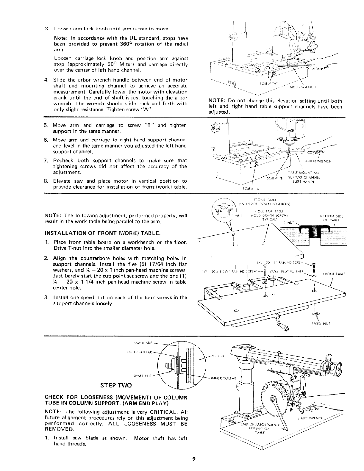
NOTE: The following adjustment, performed properly, will
result in the work table being parallel to the arm.
INSTALLATION OF FRONT (WORK) TABLE.
1. Place front table board on a workbench or the floor.
Drive T-nut into the smaller diameter hole.
2. Align the counterbore holes with matching holes in
support channels. Install the five (5) 17/64 inch flat
washers, and ¼ - 20 x 1 inch pan-head machine screws.
Just barely start the cup point set screw and the one (1)
Y4 - 20 x 1-1/4 inch pan-head machine screw in table
center hole.
3. Install one speed nut on each of the four screws in the
support channels loosely.
I
1/4 20 * I-I/4" PAN HD
_) TTOM SIDE
OF TABLE
\
SPEED NUT
CHECK FOR LOOSENESS (MOVEMENT) OF COLUMN
TUBE IN COLUMN SUPPORT. (ARM END PLAY)
NOTE: The following adjustment is very CRITICAL. All
future alignment procedures rely on this adjustment being
performed correctly. ALL LOOSENESS MUST BE
REMOVED.
1. Install saw blade as shown. Motor shaft has left
hand threads.
SHAFT WRENCH
Loading ...
Loading ...
Loading ...