Loading ...
Loading ...
Loading ...
trouble-shooting
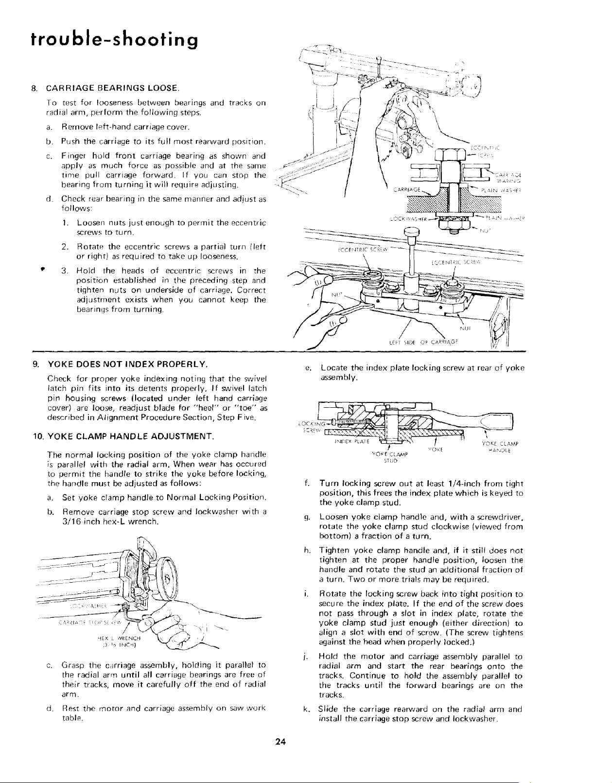
CARRIAGE BEARINGS LOOSE.
To test for looseness between bearings and tracks on
radial arm, perform the following steps,
a. Remove left-hand carriage cover.
b, Push the carriage to its full most rearward position.
c. Finger hold front carriage bearing as shown and
apply as much force as possible and at the same
time pull carriage forward. If you can stop the
bearing from turning it will require adjusting.
d. Check rear bearing in the same manner and adjust as
follows:
1, Loosen nuts just enough to permit the eccentric
screws to turn.
2. Rotate the eccentric screws a partial turn lleft
or right) as required to take up looseness.
3, Hold the heads of eccentric screws in the
position established in the preceding step and
tighten nuts on underside of carriage. Correct
adjustment exists when you cannot keep the
bearings from turning.
NU;
LEF1 SIDE OF CARRIAG
9. YOKE DOES NOT INDEX PROPERLY.
Check for proper yoke indexing noting that the swivel
latch pin fits into its detents properly, If swivel latch
pin housing screws (located under left hand carriage
cover) are loose, readjust blade for "heel" or "toe" as
described in Alignment Procedure Section, Step Five.
10. YOKE CLAMP HANDLE ADJUSTMENT.
The normal locking position of the yoke clamp handle
is parallel with the radial arm. When wear has occured
to permit the handle to strike the yoke before locking,
the handle must be adjusted as follows:
a. Set yoke clamp handle to Normal Locking Position.
b. Remove carriage stop screw and Iockwasher with a
3/16 inch hex-L wrench.
q,rX ¢lR Er'4Ct{
3 _ INCH)
L ,. / '_ '
C.
d.
Grasp the carriage assembly, holding it parallel to
the radial arm until all carriage bearings are free of
their tracks, move it carefully off the end of radial
arm.
Rest the motor and carriage assembly on saw work
table.
e. Locate the index plate locking screw at rear of yoke
assembly.
L'OC x t N_ M
CR_w
_1 voK_ HAbJOL_
YO_E CLAMP
STUD
g,
h,
k_
Turn locking screw out at least 1/4-inch from tight
position, this frees the index plate which is keyed to
the yoke clamp stud.
Loosen yoke clamp handle and, with a screwdriver,
rotate the yoke clamp stud clockwise (viewed from
bottom) a fraction of a turn.
Tighten yoke clamp handle and, if it still does not
tighten at the proper handle position, loosen the
handle and rotate the stud an additional fraction of
a turn. Two or more trials may be required.
Rotate the locking screw back into tight position to
secure the index plate. If the end of the screw does
not pass through a slot in index plate, rotate the
yoke clamp stud just enough (either direction) to
align a slot with end of screw. (The screw tightens
against the head when properly locked,)
Hold the motor and carriage assembly parallel to
radial arm and start the rear bearings onto the
tracks. Continue to hold the assembly parallel to
the tracks until the forward bearings are on the
tracks.
Slide the carriage rearward on the radial arm and
install the carriage stop screw and Iockwasher,
24
Loading ...
Loading ...
Loading ...