Loading ...
Loading ...
Loading ...
• Place the eyebolt into the hole located halfway up
the left handle and secure with cupped washer and
hex nut making sure that the cupped side of the
washer is against the handle.
• Adjust the chute directional control bracket so that
the spiral on the chute directional control fully
engages the teeth on the chute assembly. Tighten
all hardware. See Figure 13.
• Check to make sure all nuts and bolts on the control
panel and all four bolts which secure the handles to
the frame are tight.
teeth of chute here.
Figure 13
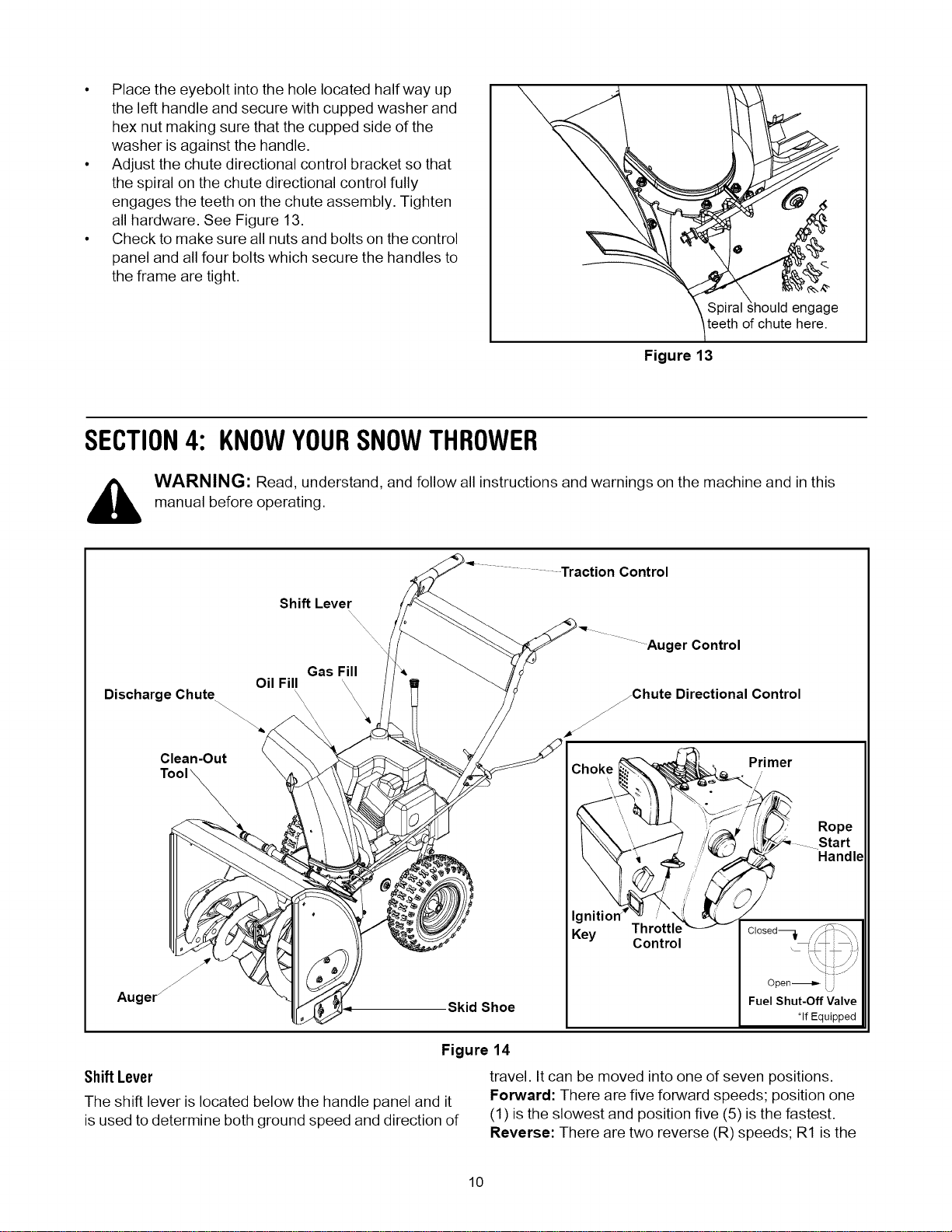
SECTION4: KNOWYOURSNOWTHROWER
,_ WARNING: Read, understand and follow all instructions and warnings on the machine and in this
manual before operating.
Control
Shift Lever
,\
Gas Fill _*
Oil Fill
Auger Control
Discharge Chute jChute Directional Control
Clean-Out
Augerj
Skid Shoe
Key Throttle
Control
Primer
Rope
Handle
Fuel Shut-Off Valve
*If Equipped
Figure 14
ShiftLever
The shift lever is located below the handle panel and it
is used to determine both ground speed and direction of
travel. It can be moved into one of seven positions.
Forward: There are five forward speeds; position one
(1) is the slowest and position five (5) is the fastest.
Reverse: There are two reverse (R) speeds; R1 is the
10
Loading ...
Loading ...
Loading ...