Loading ...
Loading ...
Loading ...
9.
Special
Functions
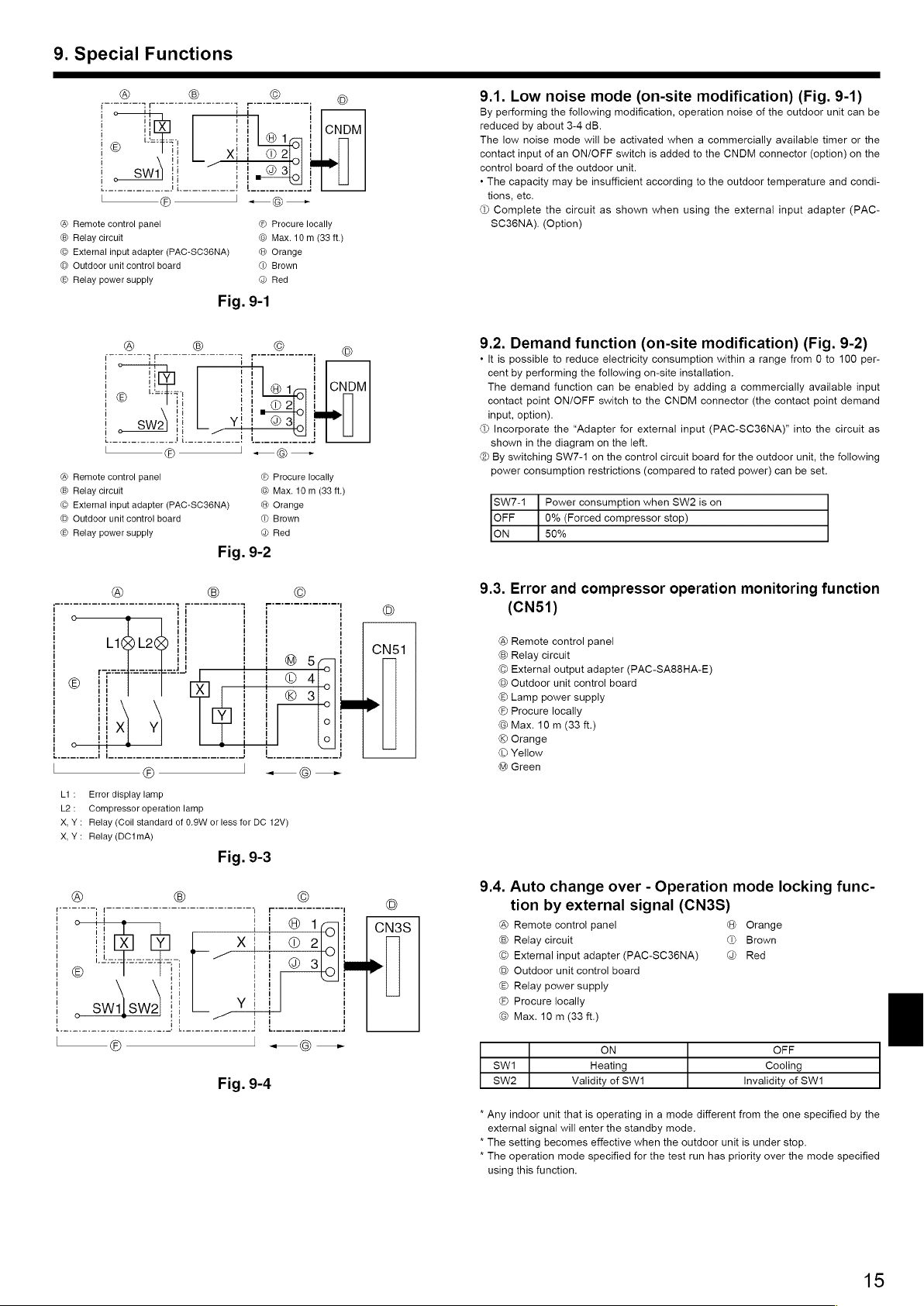
®
Remote
control
panel
Relay
circuit
©
Procure
locally
©
Max.
10
m
(33
ft.)
©
External
input
adapter
(PAC-SC36NA)
®
Orange
®
Outdoor
unit
control
board
®
Brown
©
Relay
power
supply
@
Red
Fig.
9-1
—
®-
©
io
!
eo
ty
Big
!
'
ii
a0
i
swe)
|!
O
3,
cece
eee
enw
en
|
-
L__@—_J
«—@—~-
®
Remote
control
panel
Relay
circuit
©
Procure
locally
©
Max.
10
m
(33
ft.)
©
External
input
adapter
(PAC-SC36NA)
®
Orange
®
Outdoor
unit
control
board
©
Brown
©
Relay
power
supply
@®
Red
Fig.
9-2
© ©
©
Liele
CNS1
@
5¢
© © 41,
®
3
.
—_-
°
xX;
Y
°
°
|
©
O—
Li:
Error
display
lamp
L2:
Compressor
operation
lamp
X,Y:
Relay
(Coil
standard
of
0.9W
or
less
for
DC
12V)
X,Y:
Relay
(DC1mA)
Fig.
9-3
© © ©
O16G
CN3S
X
2
‘e
©
O
©
3/6)
>
i
Y
|
©
Fig.
9-4
9.1.
Low
noise
mode
(on-site
modification)
(Fig.
9-1)
By
performing
the
following
modification,
operation
noise
of
the
outdoor
unit
can
be
reduced
by
about
3-4 dB.
The
low
noise
mode
will
be
activated
when
a
commercially
available
timer
or
the
contact
input
of
an
ON/OFF
switch
is
added
to
the
CNDM
connector
(option)
on
the
control
board
of
the
outdoor
unit.
*
The
capacity
may
be
insufficient
according
to
the
outdoor
temperature
and
condi-
tions,
etc.
@®
Complete
the
circuit
as
shown
when
using
the
external
input
adapter
(PAC-
SC36NA).
(Option)
9.2.
Demand
function
(on-site
modification)
(Fig.
9-2)
*
It
is
possible
to
reduce
electricity
consumption
within
a
range
from
0
to
100
per-
cent
by
performing
the
following
on-site
installation.
The
demand
function
can
be
enabled
by
adding
a
commercially
available
input
contact
point
ON/OFF
switch
to
the
CNDM
connector
(the
contact
point
demand
input,
option).
@®
Incorporate
the
“Adapter
for
external
input
(PAC-SC36NA)”
into
the
circuit
as
shown
in
the
diagram
on
the
left.
®
By
switching
SW7-1
on
the
control
circuit
board
for
the
outdoor
unit,
the
following
power
consumption
restrictions
(compared
to
rated
power)
can
be
set.
SW7-1
Power
consumption
when
SW2
is
on
OFF
0%
(Forced
compressor
stop)
ON
50%
9.3.
Error
and
compressor
operation
monitoring
function
(CN51)
®
Remote
control
panel
Relay
circuit
©
External
output
adapter
(PAC-SA88HA-E)
©
Outdoor
unit
control
board
®
Lamp
power
supply
©
Procure
locally
©
Max.
10
m
(33
ft.)
©
Orange
©
Yellow
@
Green
9.4.
Auto
change
over
-
Operation
mode
locking
func-
tion
by
external
signal
(CN3S)
®
Remote
control
panel
@
Orange
®
Relay
circuit
@®
Brown
©
External
input
adapter
(PAC-SC36NA)
@
Red
©
Outdoor
unit
control
board
©
Relay
power
supply
©
Procure
locally
©
Max.
10
m
(33
ft.)
ON
OFF
swi
Heating
Cooling
sw2
Validity
of
SW1
Invalidity
of
SW1
*
Any
indoor
unit
that
is
operating
in
a
mode
different
from
the
one
specified
by
the
external
signal
will
enter
the
standby
mode.
*
The
setting
becomes
effective
when
the
outdoor
unit
is
under
stop.
*
The
operation
mode
specified
for
the
test
run
has
priority
over
the
mode
specified
using
this
function.
15
Loading ...
Loading ...
Loading ...